latest progress in mimo antennas design · latest progress in mimo antennas design 5 array is an...
TRANSCRIPT

1
Latest Progress in MIMO Antennas Design
Yue Li, Jianfeng Zheng and Zhenghe Feng Tsinghua University
China
1. Introduction
Multiple-Input Multiple-Output (MIMO) wireless communication system, which is also called Multiple-Antenna system, is well known as one of the most important technologies and widely studied nowadays (Winters, 1987; Foschini & Gans, 1998; Marzetta & Hochwald, 1999; Raleigh & Cioffi, 1998). The main idea of MIMO wireless communication is to utilize the spatial degree of freedom of the wireless multi-path channel by adopting multiple antennas at both transmit and receive ends to improve spectrum efficiency and transmission quality of the wireless communication systems. MIMO technology is able to extremely improve the transmission data rates and alleviate the conflict between the increasing demand of wireless services and the scarce of electromagnetic spectrum. Two famous techniques of the MIMO systems are spatial multiplexing (SM) and transmit diversity (TD) (Nabar et al, 2002). In the scheme of SM, multiple data pipes between transmit and receive ends provide multiplexing gain to dramatically increase the channel capacity linearly with the number of antennas (Telatar, 1999; Bolcskei et al, 2002). The TD technologies, such as space-time coding, are adopted to improve the link reliability of wireless communication, especially in the multi-path fading channels (Marzetta & Hochwald, 1999; Tarokh et al, 1998; Bolcskei et al, 2001). The channel knowledge is not required in the transmit end for TD technologies. MIMO is the key technology for future wireless communication systems, such as 3GPP LTE, WiMAX 802.16, IEEE 802.20, IMT-Advanced and so on.
Although the spatial degree of freedom is important and has the potential to extremely increase the capacity of the MIMO systems, how to utilize the space resources is still needed to be studied. Physical layer design is the most important issue of wireless communication systems. Among all the components, the antenna is the interface of the MIMO wireless communication systems to the channel, which is the most sensitive part for the spatial degree of freedom. The system performance is directly dictated by the number of antennas adopted in transmit and receive end. The key issue to achieve high channel capacity of the MIMO system is the mutual coupling between antenna elements. In traditional MIMO systems, space-separated antenna array is adopted at the base station or mobile terminal. Nearly half of the wavelength is required to achieve acceptable isolation, about -15 dB for most of the situations. However, for the space is limited in both the base station and the mobile terminal, the mutual coupling between the adjacent antenna elements becomes more and more serious, restricts the performance of MIMO systems (Wallace & Jensen, 2004; Morris & Jensen, 2005). The design of antenna in space-limited MIMO system is still need further discussed. This chapter will focus on this topic.
www.intechopen.com
Wireless Communications and Networks – Recent Advances
4
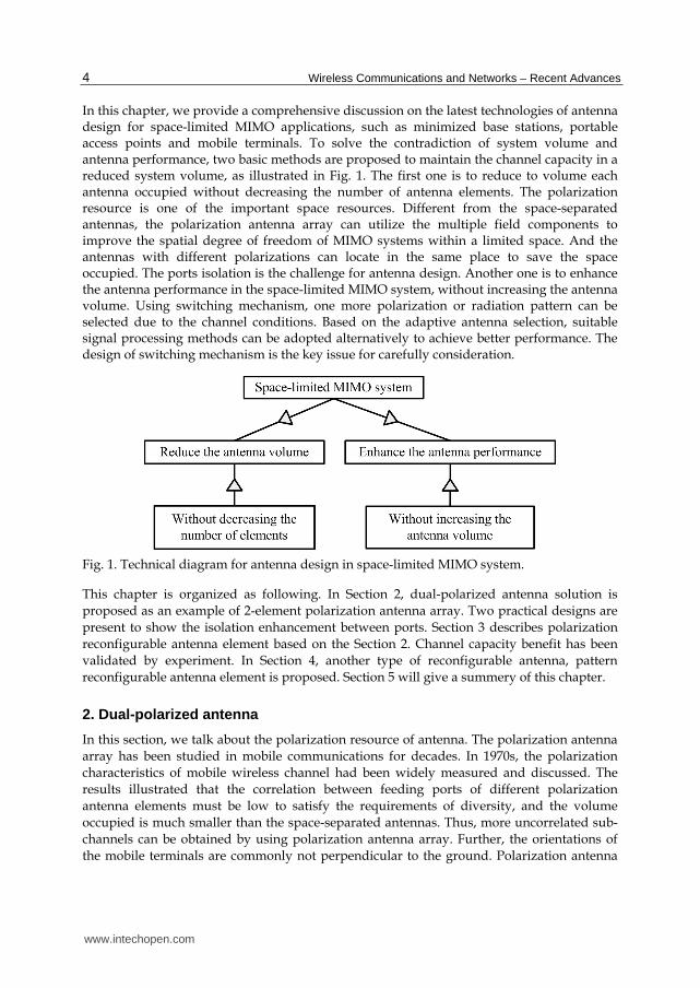
In this chapter, we provide a comprehensive discussion on the latest technologies of antenna design for space-limited MIMO applications, such as minimized base stations, portable access points and mobile terminals. To solve the contradiction of system volume and antenna performance, two basic methods are proposed to maintain the channel capacity in a reduced system volume, as illustrated in Fig. 1. The first one is to reduce to volume each antenna occupied without decreasing the number of antenna elements. The polarization resource is one of the important space resources. Different from the space-separated antennas, the polarization antenna array can utilize the multiple field components to improve the spatial degree of freedom of MIMO systems within a limited space. And the antennas with different polarizations can locate in the same place to save the space occupied. The ports isolation is the challenge for antenna design. Another one is to enhance the antenna performance in the space-limited MIMO system, without increasing the antenna volume. Using switching mechanism, one more polarization or radiation pattern can be selected due to the channel conditions. Based on the adaptive antenna selection, suitable signal processing methods can be adopted alternatively to achieve better performance. The design of switching mechanism is the key issue for carefully consideration.
Fig. 1. Technical diagram for antenna design in space-limited MIMO system.
This chapter is organized as following. In Section 2, dual-polarized antenna solution is
proposed as an example of 2-element polarization antenna array. Two practical designs are
present to show the isolation enhancement between ports. Section 3 describes polarization
reconfigurable antenna element based on the Section 2. Channel capacity benefit has been
validated by experiment. In Section 4, another type of reconfigurable antenna, pattern
reconfigurable antenna element is proposed. Section 5 will give a summery of this chapter.
2. Dual-polarized antenna
In this section, we talk about the polarization resource of antenna. The polarization antenna
array has been studied in mobile communications for decades. In 1970s, the polarization
characteristics of mobile wireless channel had been widely measured and discussed. The
results illustrated that the correlation between feeding ports of different polarization
antenna elements must be low to satisfy the requirements of diversity, and the volume
occupied is much smaller than the space-separated antennas. Thus, more uncorrelated sub-
channels can be obtained by using polarization antenna array. Further, the orientations of
the mobile terminals are commonly not perpendicular to the ground. Polarization antenna
www.intechopen.com

Latest Progress in MIMO Antennas Design
5
array is an effective solution to reduce the polarization mismatch. In traditional cellular
mobile communication systems, the system with polarization diversity antennas has a 7 dB
gain than the one with space diversity antennas in Line-of-Sight scenarios, and a 1 dB gain
in Non-Line-of-Sight scenarios (Nakano et al, 2002).
In MIMO systems, the channel capacity of MIMO system with polarization antenna array is
approximately 10%~20% higher than that with space-separated co-polarized antenna array,
though the system SNR of polarization antenna array is lower (Kyritsi et al, 2002; Wallace et
al, 2003). Another measurement results in micro- and pico-cell show the channel capacity of
MIMO systems with dual-polarized antenna elements are 14% higher than that with twice-
numbered single-polarized antennas (Sulonen et al, 2003). Similar results are also obtained
(Erceg et al, 2006). Of course, the dual-polarized antenna element can be treated as a 2-
element single-polarized antenna array. For this application, two important issues must be
considered: one is the ports isolation, the other one is the antenna dimension. High-isolated
compact-volume dual-polarized antenna is our goal of design.
In resent research, different methods of isolation enhancement are introduced. An air
bridge, which is utilized in the cross part of two feedings for high isolation, was proposed in
(Barba, 2008; Mak et al, 2007). Different feed mechanisms, feed by probe and coupling
through aperture, were used in (Guo et al, 2002). Another isosceles triangular slot antenna is
proposed for wideband dual-polarization applications in (Lee et al, 2009). TE10 and TE01
modes are excited by two orthogonally arranged microstrips. The above mentioned
methods are difficult to be realized in a compact structure and unable to be adopted in
space-limited multiple antenna systems. In this section, we introduce two compact antenna
designs with good ports isolation.
2.1 Dual-polarized slot antenna
For the purpose to realize dual orthogonal polarizations, slot structure is selected as the
main radiator. As shown in Fig. 2, both vertical and horizontal polarizations can exist
simultaneously in a rectangular slot. The operating frequency is dictated by the widths of
the slot. The slot also has the advantages of wide bandwidth, bi-directional radiation pattern
and high efficiency (Lee et al, 2009). However, how to excite these two polarizations is still a
question. The traditional method is to feed both polarizations in the same way through two
adjacent sides of the slot. Thus, the feeding structure is simple but with large dimension,
which isn’t able to fulfil our requirement of compact size.
Fig. 2. Polarization mode in slot: (a) vertical polarization, (b) horizontal polarization.
www.intechopen.com
Wireless Communications and Networks – Recent Advances
6
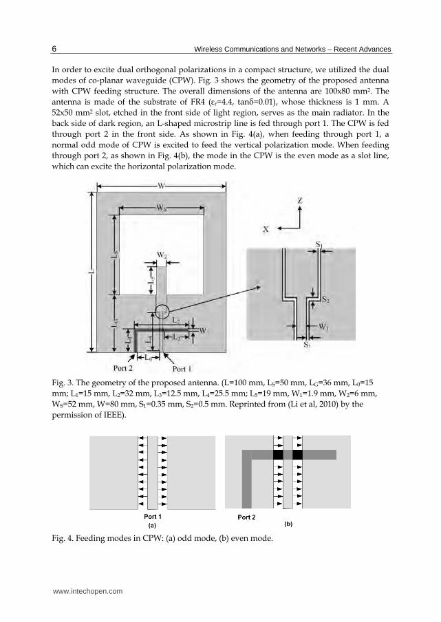
In order to excite dual orthogonal polarizations in a compact structure, we utilized the dual
modes of co-planar waveguide (CPW). Fig. 3 shows the geometry of the proposed antenna
with CPW feeding structure. The overall dimensions of the antenna are 100x80 mm2. The
antenna is made of the substrate of FR4 (┝r=4.4, tan├=0.01), whose thickness is 1 mm. A
52x50 mm2 slot, etched in the front side of light region, serves as the main radiator. In the
back side of dark region, an L-shaped microstrip line is fed through port 1. The CPW is fed
through port 2 in the front side. As shown in Fig. 4(a), when feeding through port 1, a
normal odd mode of CPW is excited to feed the vertical polarization mode. When feeding
through port 2, as shown in Fig. 4(b), the mode in the CPW is the even mode as a slot line,
which can excite the horizontal polarization mode.
Fig. 3. The geometry of the proposed antenna. (L=100 mm, LS=50 mm, LG=36 mm, L0=15
mm; L1=15 mm, L2=32 mm, L3=12.5 mm, L4=25.5 mm; L5=19 mm, W1=1.9 mm, W2=6 mm,
WS=52 mm, W=80 mm, S1=0.35 mm, S2=0.5 mm. Reprinted from (Li et al, 2010) by the
permission of IEEE).
Fig. 4. Feeding modes in CPW: (a) odd mode, (b) even mode.
www.intechopen.com

Latest Progress in MIMO Antennas Design
7
The current distributions of both polarizations are shown in Fig. 5 for better explanation. A half wavelength distribution appears on each side of slot. Dimensions of LS and WS determine the resonant frequencies of the vertical mode and horizontal mode respectively. The L3 is the tuning parameter for matching port 1. To match port 2, dimensions of W2, L5 and L6 need to be optimized. Due to the symmetric and anti-symmetric characteristics of the two modes in CPW, high isolation can be achieved between two ports. As a result, the feeding structure can excite both polarization modes simultaneously and independently.
Fig. 5. Current distributions of (a) vertical polarization and (b) horizontal polarization.
To validate the design, the S parameters of the proposed antenna are simulated using Ansoft high frequency structure simulator (HFSS). The antenna has also been fabricated and measured. Fig. 6 shows the measured S parameter of the proposed antenna in solid lines, compared with the simulated ones in dash lines. The centre frequencies of the dual polarizations are both 2.4GHz. The bandwidths of -10dB reflection coefficient are 670MHz (1.96-2.63GHz, 27.9%) and 850MHz (1.93-2.75GHz, 35.4%) for horizontal polarization and vertical polarization, respectively. Throughout the WLAN frequency band (2.4-2.484GHz), the isolation between two ports in the required band is lower than -32.6dB. These results show that the proposed antenna is simpler, more compact than the references (Barba, 2008; Mak et al, 2007; Lee et al, 2009).
Fig. 6. Simulated and measured S parameters of the proposed antenna.
www.intechopen.com

Wireless Communications and Networks – Recent Advances
8
The radiation patterns of the proposed antenna when feeding through port 1 and 2 are shown in Fig. 7 and Fig. 8. For port 1, the vertical polarization case, the 3dB beam widths are
Fig. 7. Measured and simulated radiation patterns when feeding from port 1 at 2.4 GHz: (a) X-Y plane (b) Y-Z plane.
Fig. 8. Measured and simulated radiation patterns when feeding from port 2 at 2.4 GHz: (a) X-Y plane (b) Y-Z plane.
100° and 70° in E-plane (Y-Z plane) and H-plane (X-Y plane). From these results it may be noted that the cross polarization in X-Y plane is worse than what was achieved in earlier designs as values for cross polarization are not lower than -15dB. From the radiation patterns, however, we can observe that the poles of Eφ and Eθ are almost corresponding to the maximum of each other, which means the integration of the two patterns is close to zero. In other words, the signals of co and cross polarizations are almost uncorrelated. In the Y-Z plane, the cross polarization level is sufficiently low to be ignored. For port 2, the horizontal polarization is the dominant polarization. The 3dB beam widths are 60° and 180° in E-plane (X-Y plane) and H-plane (Y-Z plane). From the above discussion, we may conclude that the signals received by the two ports are uncorrelated, so dual-polarization in single antennas can be treated as two independent antennas. The radiation efficiency and gain of the proposed antenna are also measured. In the WLAN band of 2.4-2.484GHz, the efficiency is better than 91.2% and 84.4% for port 1 and 2; and the gain is better than 3.85 dBi and 5.21
www.intechopen.com

Latest Progress in MIMO Antennas Design
9
dBi for port 1 and 2. The proposed antenna is a candidate for compact volume dual-polarized antenna application.
2.2 Dual-polarized loop antenna
The half wavelength resonant structure, such as the patch and the slot, is able to be adopted in dual-polarized antenna design. In order to realize even more compact dimension, we choose the loop antenna, whose circumference is one wavelength. The radiation patterns of the slot and the loop are almost the same. Also, the loop element can support two orthogonal polarizations using the same structure, shown in Fig. 9. Seen from these two modes, the current distribution is 90° rotated from one to another one. Good orthogonality is illustrated with high isolation. The current distribution of its one–wavelength mode is dictated by the feeding position, and feed should not be arranged at the position of the current null. However, the maximum point of one mode is the null of the other mode. It is difficult to feed the dual polarizations in one side of loop.
Fig. 9. Modes in loop antenna: (a) vertical polarization, (b) horizontal polarization.
The feeding method should be considered carefully. In order to excite two orthogonal one–wavelength modes, it is common to arrange two feeds at two orthogonal positions, which will make the overall dimension much larger. A compact size could be realized if such two modes of operation are fed at only one position. The compact CPW feed backed with
www.intechopen.com

Wireless Communications and Networks – Recent Advances
10
microstrip line adopted in the last design is an effective solution to feed the dual-mode of loop antenna. Fig. 10 shows the geometry of the loop antenna, which is quite similar as the slot design. This antenna consists of a rectangular loop, a CPW feeding and a microstrip line, and supported by the same FR4 board as last design with the thickness of 1 mm. The loop has width of 4 mm; narrower than the slot design. The loop and CPW are etched on the front side and the microstrip line is printed on the back side.
Fig. 10. Geometry of the proposed loop antenna. (L1=53 mm, L2=33 mm, L3=20 mm, L4=16 mm; L5=5.1 mm, L6=18.5 mm, L7=6.5 mm, W1=40 mm, W2=32 mm, W3=2 mm, W4=1.9 mm, S=0.5 mm. Reprinted from (Li et al, 2011a) by the permission of IEEE).
When the loop fed through port 1, the CPW operates at its typical symmetrical mode. In this mode the vertical polarization is excited. The inner conductor works as a monopole with the vertical polarization. The energy is coupled from monopole to the loop, exciting the vertical polarization mode. It is a good solution to feed the one-wavelength mode at the position of current null. The radiation consists of two modes, the one-wavelength mode of the loop and a monopole mode. When the loop is fed through port 2, the horizontal polarization of the loop antenna is excited. The feed is exactly at the maximum of current, and the horizontal mode is clearly excited in this configuration.
Fig. 11 shows the current distributions of two polarizations, which are totally different from the slot antenna. For the same application of 2.4 GHz WLAN in last design, the rectangular slot is etched in a large ground. The slot’s length and width are approximately half wavelength. For a typical slot mode, the width of extended ground is a quarter of wavelength or smaller. If the size of surrounded ground decreases to some level, the slot turns to be a loop mode with the frequency shift. What’s more, a loop has four edges with the overall dimension of the loop antenna is 40x53 mm2, including the feeding structure. The slot antenna is with the dimension of 100x80 mm2. It is clear that the area of the proposed antenna is only 26.5% of the slot one. Fig. 12 (a) and (b) show the loop antenna, in front and
www.intechopen.com

Latest Progress in MIMO Antennas Design
11
back views, respectively. Fig 12(c) shows the slot antenna design, which also operates in the same band. A significant size reduction is achieved using the loop design.
Fig. 11. Current distributions of (a) vertical polarization and (b) horizontal polarization.
Fig. 12. Photograph of the loop antenna (a) front side, (b) back side and (c) the slot antenna.the total length is one wavelength. Therefore, the dimension of a rectangular loop antenna is much smaller than the slot design with large ground. However, the slot antenna can be adopted in the array design in the same ground for special requirements.
The measured and simulated S parameters are illustrated in Fig. 13. The -10 dB bandwidth of the reflection coefficients are 770 MHz (1.98-2.75 GHz, 32.1%) for the vertical polarization and 730 MHz (1.96-2.69 GHz, 30.4%) for the horizontal polarization, both covering the of 2.4 GHz WLAN band. The isolation in this band is better than -21.3 dB, which is lower than the slot design, as a cost of dimension reduction. The isolation deterioration is mainly contributed to the feeding structure of the vertical polarization. The feeding monopole is located at the current maximum point of the horizontal mode. The energy couples between two modes. But it still fulfils the -15 dB industrial requirement.The radiation pattern s of the loop antenna is quite similar to the slot antenna, but with a lower level of cross polarization. In the 2.4 GHz WLAN band, the measured gains are better than 2.9 dBi and 4.1 dBi.
www.intechopen.com

Wireless Communications and Networks – Recent Advances
12
Considering the compact structure of loop, this antenna is suitable for the space-limited systems.
Fig. 13. Simulated and measured S parameters of the loop antenna.
3. Polarization reconfigurable antenna
As described in the introduction, reconfigurable antenna is an effective solution for the space-limited MIMO systems by adaptive antenna selection. This kind of systems is called adaptive MIMO system. The adaptive MIMO system takes the advantage of varying channel characteristics to make the best use of the improvement of channel capacity (Cetiner et al, 2004). Due to the channel condition, different antenna properties, such as polarizations and radiation patterns, are selected for better transmitting or receiving. Also, different data processing algorithms are used depending on the antenna selection. For this reason, the reconfigurable antenna is very important to the MIMO system, especially for the space-limited system. In this section, we will introduce the polarization reconfigurable antenna, based on the dual-polarized slot antenna described in the last section. In order to validate the benefit of polarization selecting, the channel capacity of a 2x2 MIMO system using the polarization reconfigurable antenna has been measured in a typical indoor scenario.
3.1 Reconfigurable mechanism
The geometry of the proposed reconfigurable slot antenna element is shown in Fig. 14, based on the design of (Li et al, 2010). The port 1 and port 2 are combined together and controlled by two PIN diodes. The port 1 is connected the microstrip line on the back side through a via hole, and controlled by PIN 1. The port 2 is connected directly to the microstrip line on the back side, and controlled by PIN 2. When PIN1 is ON and PIN2 is OFF, the antenna is fed through the port 1. The vertical polarization of the slot is excited. When PIN1 is OFF and PIN 2 is ON, the antenna is fed through the port 2, and the horizontal polarization of the slot is excited. Therefore, two ports are fed alternatively and controlled by the PIN diodes. The two PIN diodes need the bias circuit to control. Due to compact feed design, the two PIN diodes share the same bias circuit, saving the space of the antenna system and using less lumped components.
www.intechopen.com

Latest Progress in MIMO Antennas Design
13
Fig. 14. Geometry of the proposed loop antenna. (L=120 mm, LS=50 mm, LG=36 mm, L0=16 mm; L1=8.9 mm, L2=33.9 mm, L3=15.3 mm, L4=20.1 mm; L5=30 mm, W1=1.9 mm, WS=53 mm, W=80 mm, S1=0.7 mm, S2=1 mm. Reprinted from (Li et al, 2011b) by the permission of John Wiley & Sons, Inc.).
A prototype of the dual-polarized slot antenna with switching mechanism is fabricated, and shown in Fig. 15. The PIN diodes with bias circuit are on the back side of the antenna. The detailed bias circuits of two PIN diodes (D1 and D2, Philips BAP64-03) are shown in Fig. 15 (c). The ‘ON’ and ‘OFF’ states of the two PIN diodes are controlled by a 1-bit single-pole 2-throw (SP2T) switch on the front side. The bias circuit consists of three RF choke inductors (Lb1 Lb2 and Lb3, 12 nH), a DC block capacitor (Cb, 120 pF), three RF shorted capacitors (Cs1
Fig. 15. Photograph of the antenna prototype (a) front side, (b) back side; (c) bias circuit of the PIN diodes.
www.intechopen.com

Wireless Communications and Networks – Recent Advances
14
Cs2 and Cs3, 470 pF) and a bias resistor (R, 46 Ω). The bias resistor is selected depend on the value of VCC and the operating current of the PIN diode. In this application, the VCC is 3 V.
The measured reflection coefficients for both polarizations are shown in Fig. 16. Compared
with results of the dual-polarized slot antenna in Fig.13, the difference is mainly contributed
from the parasitic parameters of PIN diodes and the bias circuit. The -10dB bandwidths are
700MHz (2.02-2.72 GHz, 29.2%) and 940MHz (1.84-2.78 GHz, 40%) for vertical and
horizontal polarizations, both covering the WLAN band (2.4-2.484 GHz). The gain decreases
approximately 0.5 dB due to the insertion loss of PIN diodes.
Fig. 16. Simulated and measured S parameters of the reconfigurable antenna.
3.2 Channel capacity measurement
In this section, we measured the channel capacity of a 2x2 MIMO system in a typical indoor
scenario by using the proposed polarization reconfigurable antenna. The measurement
setup is shown in Fig.17. The measurement system consists of an Agilent E5071B Vector
network analyzer (VNA), which has 4 ports for simultaneous measurement, transmit and
receive antennas, a computer and RF cables. Two standard omni-direcitional dipoles are
utilized as the transmit antennas (TX), and arranged perpendicular to XY plane along Z axis.
Two proposed reconfigurable antennas are used as the receive antennas (RX). The 2x2
antennas are connected to the 4 ports of the VNA. The computer is used to control the
measurement procedures and record the measured channel responses. In order to validate
the improvement in channel capacity by using reconfigurable antennas, another two
reference dipoles are adopted as receive antennas for comparison. The measurement was
carried out in a room of the Weiqing building, Tsinghua University, illustrated in Fig. 18.
The framework of the room is reinforced concrete, the walls are mainly built by brick, and
the ceiling is made with plaster plates with aluminium alloy framework. The heights of
desk partition and wood cabinet are 1.4 m and 2.1 m. The transmit antennas are fixed in
the middle of room (TX). The receive antennas are arranged in several typical locales
which are noted as RX1-5 in Fig. 20. Here, the scenarios when the receive antennas are
arranged in RX1 and RX2 are line-of sight (LOS), while that is NLOS when the receive
www.intechopen.com

Latest Progress in MIMO Antennas Design
15
antennas are arranged in RX3, RX4 and RX5. In this measured, the antennas used are fixed
at the height of 0.8 m. The space of antenna elements in TX or RX is 0.5┣, with the mutual
coupling less than -25dB.
Fig. 17. Experiment setup of the measurement.
Fig. 18. Layout of measurement environment.
The measurement was carried out in the band of 2.2-2.6 GHz, with a step of 2 MHz. Three
different orientations (ZZ, YY, and XX) of RX antennas were measured to simulate different
operational poses of the mobile terminals. For two horizontal (H) and vertical (V)
polarizations reconfigurable antennas, 4 configurations (HH, HV, VH, VV) were switched
www.intechopen.com

Wireless Communications and Networks – Recent Advances
16
manually for each channel capacity measurement in a quasi-static environment, and the
result with the biggest value was chosen for statistics. Given the small-scale fading effect,
4x4 grid locations for each RX position were measured. Therefore, a total 201x3x16x2=19296
measured channel capacity for LOS condition was obtained, and 201x3x16x3=28944 was the
measured results for NLOS condition.
The channel capacity can be calculated through following formula (Foschini & Gans, 1998):
2log det[ ]r
HN n n
t
SNRC I H H
N (1)
where Nr and Nt are the numbers of RX and TX antennas. INr is a Nr x Nr identity matrix,
SNR is the signal-to-noise ratio at RX position, Hn is the normalized H, and ()H is the
Hermitian transpose. H is normalized by the received power in the 1x1 reference dipole
with identical polarization. We selected the SNR when the average channel capacity is 5
bit/s/Hz in a 1x1 reference dipole system in LOS or NLOS scenario.
The measured Complementary Cumulative Distribution Functions (CCDF) of the channel
capacity for the 2x2 MIMO system using polarization reconfigurable antennas in both LOS
and NLOS conditions are shown in Fig. 19 and 20. As summarized in Table 1, the average
and 95% outage channel capacities are both improved, especially in NLOS scenario. For
NLOS, the received signal is mainly contributed from reflection and diffraction, which vary
the polarization property of the wave. However, the path loss is higher in NLOS scenario.
The transmit power should be enhanced to guarantee the system performance. Considering
the insertion loss introduced from non-ideal PIN diodes, better capacity can be obtained by
using high quality components. The measurement results prove the benefit by using
polarization reconfigurable antennas.
Fig. 19. CCDFs of channel capacity in LOS condition.
www.intechopen.com

Latest Progress in MIMO Antennas Design
17
Fig. 20. CCDFs of channel capacity in NLOS condition.
Channel capacity Condition 1x1 dipole 2x2 dipole 2x2 polar.-reconfig.
Average LOS 5 7.86 10.62
NLOS 5 9.9 13.18
95% outage LOS 1.75 4.91 7.11
NLOS 1.94 6.87 11.32
Table 1. Average and 95% Outage Channel Capacity (bit/s/Hz).
4. Pattern reconfigurable antenna
Pattern reconfigurable antenna is another type of reconfigurable antenna. Such antenna
provides dynamic radiation coverage and mitigates multi-path fading. In this section, we
introduce a design of pattern reconfigurable antenna with compact feeding structure. The
benefit by using pattern reconfigurable antennas in the MIMO system is also proved by
experiment of channel capacity measurement.
The configuration of the pattern reconfigurable antenna is shown in Fig. 21 (a). It is
composed of an elliptical topped monopole, two Vivaldi notched slots and a typical CPW
feed with 2 PIN diodes. The antenna is printed on the both sides of a 50 x 50 mm2 Teflon
substrate, with ┝r=2.65, tan├=0.001 and thickness is 1.5 mm. The CPW is connected to the
microstrip at the back side through several via holes. A 0.2 mm wide slit is cut from the
ground on the front side for DC isolation. Three curves are used to define the shape of
antenna, fitted to the coordinates in Fig. 21 (a). Curve 1 is defined by equation (2) and curve
2 is defined by equation (3). Curve 3 and curve 2 are symmetrical along X axis.
www.intechopen.com

Wireless Communications and Networks – Recent Advances
18
Fig. 21. Geometry of the proposed loop antenna. (L1=1.74 mm, L2=28.52 mm, L3=10.74 mm,
L4=25 mm; L5=8 mm, L6=16.8 mm, L7=10mm, L8=10mm, W=50 mm, Lp=2 mm, W1=4 mm,
S1=0.3 mm. Reprinted from (Li et al, 2010c) by the permission of IEEE).
2 24( 2)( ) [ ] 1
2 2
y L Wx
W W
(2)
where 4 42L W y L , and 0.4 .
1 2c xy C e C (3)
where C1=14, C2=0.26, c=0.16.
4.1 CPW-slot transition design
Different radiation patterns are provided by different work states of the same antenna. In
order to achieve different work states, a switchable CPW-to-slotline transition with two PIN
diodes is proposed and sown in Fig. 21 (b). Three feeding modes are achieved in this
structure by varying the states of PIN diodes. When both PIN diodes are OFF, the elliptical
topped monopole is fed through a typical CPW and a nearly omni-directional radiation
pattern is achieved in XZ plane. When PIN 1 is OFF and PIN 2 is ON, the right slotline is
shorted. The left Vivaldi notched slot is fed through the left slotline (LS) of the CPW, and a
unidirectional radiation pattern is formed along the –X axis. In the same way, when PIN 1 is
ON and PIN 2 is OFF, a unidirectional beam along the +X axis is obtained in the right
Vivaldi notched slot through the right slot (RS). The proposed CPW-to-slotline transition is
able to achieve good switching from the CPW to slotline with any other extra structures.
Compared with this design, the CPW-to-slotline transition reported in (Wu et al, 2008; Kim
et al, 2007; Ma et al, 1999) all required extra structures for mode convergence, including ┣/2
phase shifter (Ma et al, 1999)and ┣/4 matching structures (Wu et al, 2008; Kim et al, 2007),
which occupy considerable space in the feed network. Such structures are not suitable for
the space-limited systems. The proposed CPW-to-slotline transition here is designed to
reduce the overall dimensions of the antenna.
www.intechopen.com

Latest Progress in MIMO Antennas Design
19
In order to explain work principle of the feed transition, the equivalent transmission line model is utilized, illustrated in Fig.22 and 23. The PIN diode is expressed as perfect conductor for ‘ON’ state and open circuit for the ‘OFF’ state. Fig. 22 (a) shows the normal CPW structure. By tuning the L5, the radiation resistance Rmonopole of monopole is matched to 50Ω at the feed port. When the right slot is shorted by PIN diode, the antenna is fed through the RS mode. The diagram and equivalent transmission line model are depicted in Fig. 22 (b). The right slotline is used to feed the Vivaldi notched slot, and the shorted left slotline works as a matching branch. The shorted branch which is less than a quarter of wavelength serves as a shunt inductance and its value is determined by its length L5. The position of the PIN diode is not fixed, and it is another freedom for impedance matching of RS feed. As shown in Fig. 23, the value of shunt inductance is jZslottan[βslot(L5-Lp)] and used to match the radiation resistance Rvivaldi. The advantage of this switchable feeding structure is that no extra structure is used in the CPW and slotline transition.
Fig. 22. Feed diagram and equivalent transmission line model. (a) CPW feed; (b) RS feed.
Fig. 23. Matching strategy of RS feed. (a) Feed diagram; (b) Transmission line model.
www.intechopen.com

Wireless Communications and Networks – Recent Advances
20
Fig. 24. Simulated and measured reflection coefficient of the reconfigurable antenna.
The selected PIN diode is Agilent HPND-4038 beam lead PIN diode, with acceptable
performance in a wide 1-10 GHz bandwidth. The bias circuit is similar as the PIN diodes
used in the last design in Fig. 15. The values of each component are determined by the
working current of the PIN diode. The efficiency decreases approximately 0.3 dB by using
this PIN diode. All the measurements were taken using an Agilent E5071B VNA. The
simulated and measured reflection coefficients of CPW feed, LS and RS feeds are shown in
Fig. 24. The measured -10dB bandwidths are 2.02-6.49 GHz, 3.47-8.03 GHz and 3.53-8.05
GHz for CPW feed, LS feed and RS feed, respectively. The overlap band from 3.53 GHz to
6.49 GHz is treated as the operation frequency for the reconfigurable patterns. The
measured normalized radiation pattern in XZ and XY planes for CPW, LS and RS feed at 4,
5, 6 GHz are shown in Fig. 25. For the CPW feed, a nearly omni-directional radiation pattern
appears in XZ plane and a doughnut shape in XY plane. For the LS or RS feed, a
unidirectional beam appears along –X or +X axis, with acceptable front-to-back ratio better
than 9.5dB. For the CPW feed, an average gain in the desired frequency range is 2.92 dBi.
For the LS and RS feed, the average gains in the 4-6 GHz band are 4.29 dBi and 4.32 dBi. The
improved gain is mainly contributed to the directivity of the slotline feed mode, and the
diversity gain is achieved by switching the patterns.
www.intechopen.com

Latest Progress in MIMO Antennas Design
21
Fig. 25. Radiation patterns of the reconfigurable antenna.
4.2 Channel capacity measurement
The channel capacity of a 2x2 MIMO system by using the proposed pattern reconfigurable antenna is measured in this section. The experiment setup is as same as Fig. 17. At the TX end, two reference dipoles are arranged perpendicular to XZ plane along Y axis. Another two reference dipoles and two proposed pattern reconfigurable antennas are adopted at the RX end alternatively for comparison. Each port of the two wire dipoles has a bandwidth of 3.9-5.9 GHz with reflection coefficient better than –6 dB, and mutual coupling between the two ports is lower than –25 dB over the frequency band which is achieved by tuning the distance between two elements. Also, the isolation between two proposed pattern reconfigurable antennas is lower than –25 dB.
The measurement was also taken in the Weiqing building of Tsinghua University of Fig. 18. The locations of RX are different from last experiment. The position of RX4 is not measured. Therefore, the LOS scenario includes the RX1 and RX2, and the NLOS scenario includes the RX3 and RX5. The frequency range of measurement is 4-6 GHz, with a step of 10 MHz. A total number of 201 data points/results are obtained as samples. Three configurations (CPW, LS and RS) of each reconfigurable element of the receive end were switched together manually and the highest value signal was selected as the receiving signal. Also, considering the small-scale fading effect, 5x5 grid locations for each RX position were arranged. A total number of 2x201x25=10050 results were measured for LOS and NLOS scenarios respectively. In the measurement, a 2x2 channel matrix H is obtained. The channel capacity is calculated by formula (1) in the last section. We also selected the SNR when the average channel capacity is 5 bit/s/Hz in a 1x1 reference dipole system in LOS or NLOS scenario.
The measured CCDFs of channel capacity of LOS and NLOS scenarios are illustrated in Fig. 26 and 27. The results consist of the channel capacity information of 2x2 multiple antenna
www.intechopen.com

Wireless Communications and Networks – Recent Advances
22
system using the proposed pattern reconfigurable antennas, compared with 1x1 and 2x2 systems using reference dipoles. As listed in Table 2, 2.28 bit/s/Hz and 4.13 bit/s/Hz of the average capacity enhancement are achieved in LOS and NLOS scenarios, and 2.51 bit/s/Hz and 3.75 bit/s/Hz enhancement for 95% outage capacities. In the NLOS scenario, the received signal is mainly contributed from reflection and diffraction of the concrete walls and the desk partitions, arriving at the direction of endfire. The diversity gain in the endfire increases the channel capacity. Considering the insertion loss introduced from the non-ideal PIN diodes, better performance of the proposed antenna can be achieved by using high quality switches, such as micro-electro-mechanical systems (MEMS) type switches with less insertion loss and parasitic parameters.
Fig. 26. CCDFs of channel capacity in LOS condition.
Fig. 27. CCDFs of channel capacity in NLOS condition.
www.intechopen.com

Latest Progress in MIMO Antennas Design
23
Channel Capacity Scenario 1x1 Dipole 2x2 Dipole 2x2 Pattern Reconfig.
Average LOS 5 9.46 11.74
NLOS 5 9.93 13.06
95% Outage LOS 2.29 4.21 6.72
NLOS 1.68 5.41 9.16
Table 2. Average and 95% Outage Channel Capacity (bit/s/Hz).
5. Conclusion
This chapter has introduced the now trend of antenna design in MIMO systems. From a
view of antenna design, it is difficult to achieve good performance by using traditional
antennas in space-limited MIMO systems. The mutual coupling between the antenna
elements deteriorates the independence among multiple channels in MIMO systems. For
both techniques of TD and SM, the benefit of multiple channels is difficult to be obtained
due to the space limitation. However, the usage of miniaturized mobile terminals is popular
and their size is getting much smaller. Here comes the contradiction between the antenna
performance and the ministration of mobile handsets.
In this chapter, we are aimed to solve the space problem of antennas in MIMO systems. Two effective solutions are introduced here. The first one is to use polarization, an important spatial resource, to take the place of antenna element. Two orthogonal polarized antenna elements can be arranged together with acceptable isolation. In this way, the space between antenna elements is saved, making the overall antenna system more compact. As an important practical application, two types of dual-polarized antennas are presented and analyzed. Isolation enhancement methods are proposed, such as the feed design and operation modes design. The proposed antennas show the advantages of compact structure, high ports isolation and easy fabrication, and are suitable to be adopted in the space-limited MIMO systems.
Considering in the opposite way, the antennas with better performance in the original space
is another solution in space-limited MIMO systems. The reconfigurable antenna is a
prevalent type of antenna nowadays. Switching mechanism is added to achieve selectable
polarizations, radiation patterns and other property. Different antenna configurations and
corresponding signal processing methods are selected due to the channel information. The
switching mechanism is the most important issue. Based on the dual-polarized slot antenna
design, the PIN diodes are used to achieve polarization selection. A pattern reconfigurable
antenna is design by using a switchable CPW-to-slotline feeding structure. In order to prove
the benefit of the antenna selection, we design an experiment of channel capacity in a typical
indoor environment. The results show that the channel capacity improves in both LOS and
NLOS scenarios, especially in NLOS scenario. The reconfigurable antenna shows the
potential application in space-limited MIMO systems.
6. Acknowledgment
This work is supported by the National Basic Research Program of China under Contract 2009CB320205, in part by the National High Technology Research and Development
www.intechopen.com

Wireless Communications and Networks – Recent Advances
24
Program of China (863 Program) under Contract 2009AA011503, the National Science and Technology Major Project of the Ministry of Science and Technology of China 2010ZX03007-001-01, and Qualcomm Inc..
7. References
Barba, M. (2008). A High-Isolation, Wideband and Dual-Linear Polarization Patch Antenna. IEEE Transactions on Antenna and propagation, vol.56, No.5, (May 2008), pp. 1472-1476, ISSN 0018-926X.
Bolcskei, H.; Nabar, R.; Erceg, V.; Gesbert, D. & Paulraj A. (2001). Performance of spatial multiplexing in the presence of polarization diversity. Proceedings of IEEE International Conference on Acoustics, Speech, and Signal Processing, pp. 2437-2440, ISBN 0-7803-7041-4, Salt Lake City, Utah, USA, May 7-11, 2001
Bolcskei, H.; Gesbert, D. & Paulraj A. (2002). On the capacity of OFDM based spatial multiplexing systems. IEEE Transactions on Communications, vol.50, No.2, (February 2002), pp. 225-234, ISSN 0090-6778.
Cetiner, B..; Jafarkhani, H.; Qian, J.; Hui, J.; Grau, A. & De Flaviis, F. (2004). Multifunctional reconfigurable MEMS integrated antennas for adaptive MIMO systems. IEEE Communications Magazine, vol.42, (December 2004), pp. 62-70, ISSN 0163-6804.
Erceg, V.; Sampath, H. & Catreux-Erceg, S. (2006). Dual-Polarization versus single-polarization MIMO channel measurement results and modeling. IEEE Transactions on Wireless Communication, vol.5, No.1, (January 2006), pp. 28-33, ISSN 1536-1276.
Foschini, G. & Gans, M. (1998). On limits of wireless communications in a fading environment when using multiple antennas. Wireless Personal Communications, vol.6, No.3, (Mar 1998), pp. 311-335, ISBN 0201634708.
Guo, Y.; Luk, K. & Lee K. (2002). Broadband dual polarization patch element for cellular-phone base stations. IEEE Transactions on Antenna and propagations, vol.50, No.2, (February 2002), pp. 251-253, ISSN 0018-926X.
Kim, H.; Chung, D.; Erceg, V.; Anagnostou, D. & Papapolymerou, J. (2007). Hardwired Design of Ultra-Wideband Reconfigurable MEMS Antenna. Proceedings of IEEE 18th International Symposium on Personal, Indoor and Mobile Radio Communications, pp. 1-4, ISBN 1-4244-1144-0, Athens, Greece, September 3-7, 2007.
Kyritsi, P.; Cox, D.; Valenzuela, R. and Wolniansky, P. (2002). Effect of antenna polarization on the capacity of a multiple element system in an indoor environment. IEEE Journal on Selected Areas in Communications, vol.20, No.6, (August 2002), pp. 1227-1239, ISSN 0733-8716.
Lee, C.; Chen, S. & Hsu, P. (2009). Isosceles Triangular Slot Antenna for Broadband Dual Polarization Applications. IEEE Transactions on Antenna and propagations, vol.57, No.10, (October 2009), pp. 3347-3351, ISSN 0018-926X.
Li, Y.; Zhang, Z.; Chen, W.; Feng, Z. & Iskander, M. (2010). A dual-polarization slot antenna using a compact CPW feeding structure. IEEE Antennas and Wireless Propagations Letter, vol.9, (December 2009), pp. 191-194, ISSN 1536-1225.
Li, Y.; Zhang, Z.; Feng, Z. & Iskander, M. (2011). Dual-mode Loop Antenna with Compact Feed for Polarization Diversity. IEEE Antennas and Wireless Propagations Letter, vol.10, (December 2010), pp. 95-98, ISSN 1536-1225.
www.intechopen.com

Latest Progress in MIMO Antennas Design
25
Li, Y.; Zhang, Z.; Zheng, J. & Feng, Z. (2011). Channel capacity study of polarization reconfigurable slot antenna for indoor MIMO system. Microwave and Optical Technology Letters, vol.53, No.6, (March 2011), pp. 1029-1213, ISSN 1098-2760.
Li, Y.; Zhang, Z.; Zheng, J.; Feng, Z. & Iskander, M. (2011). Experimental Analysis of a Wideband Pattern Diversity Antenna with Compact Reconfigurable CPW-to-Slotline Transition Feed. IEEE Transactions on Antenna and propagations, accepted for publication, ISSN 0018-926X.
Lin, Y. & Chen, C. (2000). Analysis and applications of a new CPW-slotline transition. IEEE Transactions on Microwave Theory and Techniques, vol.48, No.3, (March 2000), pp. 463-466, ISSN 0018-9480.
Ma, K.; Qian, Y. & Itoh, T. (1999). Analysis and applications of a new CPW-slotline transition. IEEE Transactions on Microwave Theory and Techniques, vol.47, No.4, (April 1999), pp. 426-432, ISSN 0018-9480.
Mak, K.; Wong, H. & Luk, K. (2007). A Shorted Bowtie Patch Antenna with a Cross Dipole for Dual Polarization. IEEE Antennas and Wireless Propagations Letter, vol.6, (June 2007), pp. 126-129, ISSN 1536-1225.
Marzetta, T. & Hochwald, B. (1999). Capacity of a mobile multiple-antenna communication link in Rayleigh flat fading. IEEE Transactions on Information Theory, vol.45, No.1, (January 1999), pp. 139-157, ISSN 0018-9448.
Morris, M. & Jensen, M. (2005). Superdirectivity in MIMO systems. IEEE Transactions on Antenna and propagation, vol.53, No.9, (September 2005), pp. 2850-2857, ISSN 0018-926X.
Nabar, R.; Bolcskei, H.; Erceg, V.; Gesbert, D. & Paulraj A. (2002). Performance of multi-antenna signaling techniques in the presence of polarization diversity. IEEE Transactions on Signal Processing, vol.50, No.10, (October 2002), pp. 2553-2562, ISSN 1053-587X.
Nakano, M.; Satoh, T.; & Arai, H. (2002). Uplink polarization diversity measurement with human body effect at 900 MHz. Electronics and Communications in Japan, vol.85, No.7, (July 2002), pp. 32-44, ISSN 1520-6424.
Raleigh, G. & Cioffi, J. (1998). Spatio-temporal coding for wireless communication. IEEE Transactions on Communications, vol.46, No.3, (March 1998), pp. 357-366, ISSN 0090-6778.
Shin, J.; Chen, S. & Schaubert, D. (1999). A parameter study of stripline-fed Vivaldi notch-antenna arrays. IEEE Transactions on Antenna and propagations, vol.47, No.5, (May 1999), pp. 879-886, ISSN 0018-926X.
Sulonen, K.; Suvikmnas, P.; Vuokko, L.; Kivinen, J. and Vainikainen, P. (2003). Comparison of MIMO antenna configurations in Picocell and Microcell environments. IEEE Journal on Selected Areas in Communications, vol.21, No.5, (June 2003), pp. 703-712, ISSN 0733-8716.
Tarokh, V.; Seshadri, N.; & Calderbank, A. (1998). Space-time codes for high data rate wireless communication: performance criterion and code construction. IEEE Transactions on Information Theory, vol.44, No.2, (March 1998), pp. 744-765, ISSN 0018-9448.
Telatar, I. (1999). Capacity of multi-antenna Gaussian channels. European Transactions on Telecommunications, vol.10, No.6, (December 1999), pp. 585–595, ISSN 1541-8251.
www.intechopen.com

Wireless Communications and Networks – Recent Advances
26
Wallace, J.; Jensen, M. Swindlehurst, A. & Jeffs, B. (2003). Experimental characterization of the MIMO wireless channel: Data acquisition and analysis. IEEE Transactions on Wireless Communication, vol.2, No.2, (March 2003), pp. 335-343, ISSN 1536-1276.
Wallace, J. & Jensen, M. (2004). Mutual coupling in MIMO wireless systems: A rigorous network theory analysis. IEEE Transactions on Wireless Communication, vol.3, No.4, (July 2004), pp. 2437-2440, ISSN 1536-1276.
Winters, J. (1987). On the capacity of radio communication systems with diversity in a Rayleigh fading environment. IEEE Journal on Selected Areas in Communications, vol.5, No.5, (June 1987), pp. 871-878, ISSN 0733-8716.
Wu, S.; Chen, S. & Ma, T. (2008). A Wideband Slotted Bow-Tie Antenna with Reconfigurable CPW-to-Slotline Transition for Pattern Diversity, IEEE Transactions on Antenna and propagations, vol.56, No.2, (February 2008), pp. 327-334, ISSN 0018-926X.
www.intechopen.com

Wireless Communications and Networks - Recent AdvancesEdited by Dr. Ali Eksim
ISBN 978-953-51-0189-5Hard cover, 596 pagesPublisher InTechPublished online 14, March, 2012Published in print edition March, 2012
InTech EuropeUniversity Campus STeP Ri Slavka Krautzeka 83/A 51000 Rijeka, Croatia Phone: +385 (51) 770 447 Fax: +385 (51) 686 166www.intechopen.com
InTech ChinaUnit 405, Office Block, Hotel Equatorial Shanghai No.65, Yan An Road (West), Shanghai, 200040, China
Phone: +86-21-62489820 Fax: +86-21-62489821
This book will provide a comprehensive technical guide covering fundamentals, recent advances and openissues in wireless communications and networks to the readers. The objective of the book is to serve as avaluable reference for students, educators, scientists, faculty members, researchers, engineers and researchstrategists in these rapidly evolving fields and to encourage them to actively explore these broad, exciting andrapidly evolving research areas.
How to referenceIn order to correctly reference this scholarly work, feel free to copy and paste the following:
Yue Li, Jianfeng Zheng and Zhenghe Feng (2012). Latest Progress in MIMO Antennas Design, WirelessCommunications and Networks - Recent Advances, Dr. Ali Eksim (Ed.), ISBN: 978-953-51-0189-5, InTech,Available from: http://www.intechopen.com/books/wireless-communications-and-networks-recent-advances/latest-progress-in-mimo-antennas-design

© 2012 The Author(s). Licensee IntechOpen. This is an open access articledistributed under the terms of the Creative Commons Attribution 3.0License, which permits unrestricted use, distribution, and reproduction inany medium, provided the original work is properly cited.