latest advancements in modelling and simulation in … · latest advancements in modelling and...
TRANSCRIPT

1
ALUCAST India 2010
ALUCAST India 2010 : Christian Kleeberg - MAGMA Engineering Asia-Pacific Pte Ltd - Singapore
Latest Advancements in Modelling and Simulation for
High Pressure Die Castings
Christian Kleeberg, MAGMA Engineering Asia-Pacific Pte Ltd, Singapore
1.0 Introduction: Innovations and modifications in the techniques of high pressure die casting or tooling are forced by trends in part design, part load as well as by costs and times for development and manufacturing processes. All current trends require continuous improvement in planning of part performance and production processes. The quality of parts and the efficiency of development and manufacturing processes are primarily depending on the quality and accuracy of the planning process.
Generally, there are two crucial factors that secure the reliability of planning:
• Experiences from past projects that can be used in future projects, and
• Modelling and simulation of processes based on general physical laws.
In high pressure die casting the term ‘modelling’ means the reproduction of the casting process in simulation programs. In this method, the very detailed process flow is specified as a boundary condition in a calculation. The result is the representation of die filling, solidification, formation of microstructure and properties, as well as development of residual stress and distortion in the castings.
As this is the quickest and most cost-effective method to develop a high-value product, die casting modelling and simulation gets more and more important.
1.1 Model Requirements
Basically, the term ‘modelling’ means the idealized replication of an object or of a process. A good model mirrors the essential characteristics of the original, but at the same time uses valid and clever simplifications. The modelling of a complex, technical operation like the high pressure die casting process means to define, to quantify, and to take into consideration the characteristic values and influential mechanisms of the process (P. N. Hansen et al., 2001, W. Maus et al., 2001).
The simulation of die casting needs to replicate the following typical problems: Patterns and temperatures in the melt flow: last filled areas, venting of the die, aggregation of die agents, ‘dead areas’ in the runner, turbulences in the melt, disintegration of the melt and merging of melt fronts, cold shuts, or weld lines.
Temperatures of the die: the complete die filling (especially during thin-wall casting), cycle times, core wear, adhesive tendency, or heat loss when spraying.
Solidification of the casting: the creation of shrinkage cavities and pores, hot tears, microstructure formation, possible feeding in the final pressure phase or during local squeezing, as well as the formation of residual stress and consequently arising distortion.
The integration of the simulation results into the decision making processes during casting design or in the foundry assumes that the calculations generally last no longer than one day, counting from the availability of an accurate 3D-CAD-model of a casting including ingates to the creation of the documentation of the calculation.

2
ALUCAST India 2010
ALUCAST India 2010 : Christian Kleeberg - MAGMA Engineering Asia-Pacific Pte Ltd - Singapore
2.0 Requirements for HPDC process simulation In order to run a casting simulation, the following fundamental steps need to be carried out.
2.1. 3-D-modeling
Basis for the simulation is a three-dimensional geometry model of the raw casting or the machined part. The casting developers in the automotive industry focus on maintaining a centrally managed and up-to-date record of geometries that exclusively consists of 3D-CAD data. This way it is nearly impossible that such model doesn’t exist in the automotive industry. In other industries it might happen that a model is not existent and it needs to be developed based on drawings. The geometries of ingates and overflows, as well as of die segments including cooling/heating lines are prepared as 3D-models and need to be available for the simulation, too.
Figure (1) and (2): Typical 3 D model using state-of-the-art modelling tools
2.2. Enmeshment
The complete 3D-model, which consists of the raw casting, in-gates, overflows and/or vacuum channels, as well as die segments including cooling/heating lines need to be enmeshed for the mathematical calculation. Depending on the operation method, these meshes are exclusively automatically generated (finite volume method), or automatically generated and manually reworked (finite elements method). The completion of the 3D-models and the enmeshment are known as ’pre-processing’.

3
ALUCAST India 2010
ALUCAST India 2010 : Christian Kleeberg - MAGMA Engineering Asia-Pacific Pte Ltd - Singapore
2.3. Comprehensive Process description Before starting the simulations, the required process parameters need to be entered via interactive user interfaces. These process parameters are shot curve, temperatures of melt, thermal regulation medium and die, as well as the chronological sequence of the whole casting process including the spraying of the die agent. Some simulation programs include subroutines that automatically forecast and propose appropriate process parameters.
2.4. Execution of the calculations
The actual calculation can be carried out on various hardware platforms. The complete calculations usually run overnight on powerful machines, but with the use of cluster computers and appropriate simulation programs, the calculation can be completed within minutes (W. Schäfer et al., 2000).
2.5. Evaluation of the results
Postprocessors’ prepare the results in coloured graphics or movies that visualize and document the calculated operations during die filling, solidification, formation of microstructure and properties, as well as the formation of residual stress and distortion. State-of-the-art simulation programs can do automatic or semi-automatic evaluation of results in various iterations at the same time for easy comparison. Engineering time is most valuable spent when good post-processing is applied and decision making is administrated based on results achieved.
Figure (3): Typical result in a state-of-the-art postprocessor environment (here: filling result (left); solidification result (right)

4
ALUCAST India 2010
ALUCAST India 2010 : Christian Kleeberg - MAGMA Engineering Asia-Pacific Pte Ltd - Singapore
3.0. Simulation of the entire casting process The casting filling is often seen as the most critical and for the casting result the most influential sub-process in high pressure die casting. Apart from some exceptions that require a slow die filling (like infiltration of inserts made of ceramic fibres) the ingate velocities lie in a range between 30 and 140 m/s and the filling times are between 20 and 200 ms. These conditions lead to a turbulent flow, where, due to the geometries of the castings, the melt fronts are nearly always uneven. The flow consists of at least two phases (liquid and gas) and in some cases additionally of a solid phase during the die filling.
State-of-the-art simulation technologies provide a magnitude of results files for filling that allow designers, casting engineers and all people engaged in the casting process and up to top management to make sound decisions for improvements of bottom lines. In the following various comprehensive result files are described hereafter
3.1. Filling Results and flow in the gating system:
Due to various reasons, the gating design is very important in high pressure die casting. Regarding the design of the gate, the following needs to be taken into consideration:
• Turbulences in the melt should be reduced in order to avoid entrapped gas in the casting
• The melt flow through the gate needs to be timed in order to allow the controlled merging of the melt fronts
• The flow velocities need to be consistent, also when using fan ingates
• The desired direction of the melt flow into the cavity needs to be met
• The die filling simulation based on an existing design of the gating system allows to evaluate all these problems, and thus to decide if the design is usable or needs to be modified
Figure (4): Filling result in a gating system using "X-ray mode" for temperatures (left) and velocities (middle). In addition volume tracer can show internal turbulences (right) Further to the above mentioned, state-of-the-art modelling and simulation tools should provide a variety of results that allow designers, die-casters, quality inspection staff and also management to make sound and informed decision for casting performance and engineering competence. In this context it is extremely important to mention that all results should one way or the other support each engineering decision making step and should complement the know-how and expertise of the simulation tool users. In the following (Figure (5) - (9)) are some typical result files mentioned that should be taken into consideration when applying modelling and simulation of high pressure die-casting parts.

5
ALUCAST India 2010
ALUCAST India 2010 : Christian Kleeberg - MAGMA Engineering Asia-Pacific Pte Ltd - Singapore
Examples of modelling and simulation result files for filling simulation: Figure 5) Venting/Vacuum / Air Back Pressure & Air Entrapment
Figure 6) Material Age and Air Contact
Figure 7) Filling & entrapped Air in reverse filling
6
ALUCAST India 2010
ALUCAST India 2010 : Christian Kleeberg - MAGMA Engineering Asia-Pacific Pte Ltd - Singapore
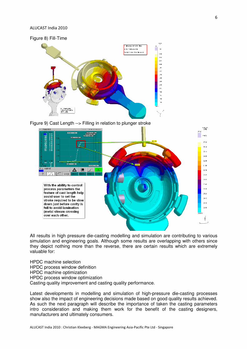
Figure 8) Fill-Time
Figure 9) Cast Length --> Filling in relation to plunger stroke
All results in high pressure die-casting modelling and simulation are contributing to various simulation and engineering goals. Although some results are overlapping with others since they depict nothing more than the reverse, there are certain results which are extremely valuable for: HPDC machine selection HPDC process window definition HPDC machine optimization HPDC process window optimization Casting quality improvement and casting quality performance. Latest developments in modelling and simulation of high-pressure die-casting processes show also the impact of engineering decisions made based on good quality results achieved. As such the next paragraph will describe the importance of taken the casting parameters intro consideration and making them work for the benefit of the casting designers, manufacturers and ultimately consumers.
7
ALUCAST India 2010
ALUCAST India 2010 : Christian Kleeberg - MAGMA Engineering Asia-Pacific Pte Ltd - Singapore
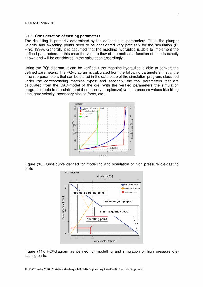
3.1.1. Consideration of casting parameters
The die filling is primarily determined by the defined shot parameters. Thus, the plunger velocity and switching points need to be considered very precisely for the simulation (R. Fink, 1999). Generally it is assumed that the machine hydraulics is able to implement the defined parameters. In this case the volume flow of the melt as a function of time is exactly known and will be considered in the calculation accordingly.
Using the PQ²-diagram, it can be verified if the machine hydraulics is able to convert the defined parameters. The PQ²-diagram is calculated from the following parameters; firstly, the machine parameters that can be stored in the data base of the simulation program, classified under the corresponding machine types; and secondly, the tool parameters that are calculated from the CAD-model of the die. With the verified parameters the simulation program is able to calculate (and if necessary to optimize) various process values like filling time, gate velocity, necessary closing force, etc..
Figure (10): Shot curve defined for modelling and simulation of high pressure die-casting parts
Figure (11): PQ²-diagram as defined for modelling and simulation of high pressure die-casting parts.

8
ALUCAST India 2010
ALUCAST India 2010 : Christian Kleeberg - MAGMA Engineering Asia-Pacific Pte Ltd - Singapore
3.2. Casting solidification simulation and results for squeezing / feeding of high-pressure die-cast parts
The solidification of the melt is characterized by a number of metallurgical-physical phenomena that eventually determine the local properties of the casting. Those need to be considered in the simulation with appropriate modelling approaches. The main aspects in high pressure die casting are the shrinkage during solidification and the microstructure formation. The volume contraction during the solidification of the metal melt leads to shrinkage cavities and dispersed porosity depending on the alloy and the wall thickness of the casting. Heavy sections of the casting usually form a stable metal skin, whereas thin walls and especially the in-gate start to freeze quickly. For this reason, feeding can only be used as a compensation of the shortfall in volume if the in-gates are thicker than the wall of the casting, where further feeding is necessary (exception here is local squeezing).
The simulation allows an easy determination of areas where solidification shrinkage can lead to volume errors (S. Kluge, 1999). The simplest criterion is the solidification time. The possibility to partially compensate the solidification shrinkage by feeding with the plunger or with the local squeezer can also be displayed. The solidification sequence allows to determine exactly the time allowed for pressure feeding.
Figure (12). Solidification sequence of a die-casting part
3.2.1. Correlation of calculated and measured porosity
In the past years, computer tomography (CT) has been increasingly used in the area of quality assurance. As imperfections can be exactly localized and results are very accurate, the computer tomography is a great support for casting simulation.
Figure (12) is showing an excellent agreement between a simulation result and a CT result on a gear box housing.

9
ALUCAST India 2010
ALUCAST India 2010 : Christian Kleeberg - MAGMA Engineering Asia-Pacific Pte Ltd - Singapore
Figure (13) shows comparison and good agreement between simulation result and CT scan 3.3. Local Squeezing
Shrinkage cavities are acceptable in some die castings; however, they generally cause problems during mechanical exposure and during machining of the casting. Shrinkage cavities always occur in heavy sections that are functionally necessary in many die castings. There are only a few possibilities to avoid shrinkage cavities, if the design of the casting can’t be modified. One of those possibilities is local squeezing.
The example in Figure (14) represents the dimensioning of a squeezing system that should be used for the forced feeding of a critical area in the casting (Fig. 15).
Figure (14): Long solidification times (left) and a local squeezing system before and after correct dimensioning (right).
3.4. Porosity Visualization
The most important result in solidification simulation is the visualization of porosity formation in a given casting. As such it is important here not only to have a qualitative result but very much a quantitative result. Figure 14 shows such result in form of a transparent view (X-ray view) whereas sound material is transparent and certain level of porosity of whatever origin is marked with a colour code and visible.

10
ALUCAST India 2010
ALUCAST India 2010 : Christian Kleeberg - MAGMA Engineering Asia-Pacific Pte Ltd - Singapore
Figure (15) Porosity formation inside a die-casting part. Sound areas are transparent.
3.5. Shot chamber Simulation There is an increasing trend to simulate the behaviour of the shot chamber in a multi cycle die-casting environment. Due to the fact that ultimately the melt has to be forced through thin in-gates it is - among the expert - a continuous subject of discussion whether such shot chamber simulation provides any additional information for optimization.
Figure (16): Simulation of the shot chamber in multi cycle die-casting environment.

11
ALUCAST India 2010
ALUCAST India 2010 : Christian Kleeberg - MAGMA Engineering Asia-Pacific Pte Ltd - Singapore
3.6. Die Soldering and Die lifetime
High temperature gradients that develop during the casting cycle in the die reduce the lifetime of the die. Purpose of optimization is the minimization of temperature gradients at certain locations of the die and at certain times of the casting cycle. State-of-the-art simulation tools have so-called die-soldering criterion linked to the heat-up and solidification of the melt on the surface of the die. In addition thermal balancing can be achieved used 3D layouts of the die and analyzing the temperature distribution.
Figure (17): Die-casting die with soldering problems and temperature gradients in a sliced view thru the cooling channel
3.7. Distortion of castings after shake-out / ejection
Basically, in every casting with different wall thicknesses occur residual stresses. Different wall thicknesses of the casting lead to different cooling behaviour after pouring as well as after heat treatment and thus result in residual stresses and in distortion of the casting (A. Egner-Walter, 1999). Usually, this distortion lies in an acceptable range.
The development of residual stress until the removal of the in-gate is initially calculated based on the results of the solidification simulation and during the cooling of the casting. Depending on the proportion between cross section of the in-gate and wall thickness of the casting, the removal time of the in-gate has a significant influence on the development of residual stress as this process leads to stress transfer in the casting
Figure (18): Distortion of a die casting in a magnified view. The casting experienced stresses and distortion after shake-out / ejection and after removal of in-gate.

12
ALUCAST India 2010
ALUCAST India 2010 : Christian Kleeberg - MAGMA Engineering Asia-Pacific Pte Ltd - Singapore
3.8. Prediction of casting distortions - Agreements with measurements
The simulation of stress and distortion in the frame is always advisable when huge castings like engine blocks or castings with a large projected area, like structural components, are combined with tight tolerances (due to dimensional limitations of the machine).
Once the simulation is performed it is advisable to do measurements and provide the necessary correlations between deformations of the structural component in the simulation and the actual deformations in reality. Figure (19) shows such correlation work executed on door frame casting manufactured for a European car producer.
Figure (19): Correlation of simulated (red) and measured (blue) results of a deformation of a structural die casting component
3.9. Hot Tear in Die-Cast parts
Another phenomenon that occurs in die-casting parts are hot tears. The hot tear forms when already solid areas cool down further whereas other areas of a casting are still in the "mushy" zone , meaning liquidus and solidus temperature. In principle this "pulling" of masses are a result of induced stresses and such can be addressed with state-of-the-art modelling and simulation tools. Figure 20 shows an example of such hot-tear detection.
Figure (20) Prediction of a hot tearing in comparison with actual casting findings

13
ALUCAST India 2010
ALUCAST India 2010 : Christian Kleeberg - MAGMA Engineering Asia-Pacific Pte Ltd - Singapore
3.10. Prediction of die stresses and assessments of die life-time and influence of spraying on die-life predictions
Temperatures in a die casting tool can differ significantly. High pressure die casting dies in Aluminum applications can reach temperatures of more than 450°C near the impressions just after the filling. Temperatures close to the cooling channels are much lower (Fig. 24). Due to the temperature gradients appearing in all high pressure dies, residual stresses arise especially in the die insert, where the tool steel load can reach the yield point (Fig. 25). Compressive and tensile stresses successively occur due to strong temperature changes that are also caused by spraying of die agents. This leads to the development of cracks, especially in slim cores, where big changes in temperature happen due to intense heating up and cooling (spraying).
For the evaluation of stress in the inserts, the thermal residual stress is a considerable part of the overall load. The thermal shocks in each cycle caused by the melt and later by the die agent in correlation with the die tempering generate inhomogeneous and cyclically unsteady temperature distributions with partially very high gradients. This results in thermal residual stresses, where a likewise cyclically changing distortion is especially important for the lifetime of the die insert. These calculations need to be carried out with non-linear, elastoplastic model approaches, too.
Figure 21 shows example of die-cracks in actual and in simulation. The agreement between the results is visible. Such examples allow die -designers and casting manufactures to make sound decisions on die-thermal layouts and balancing for maximum performance of die lifetime and shot yield. (reference [5])
Figure (21): 2 examples of a surface quality of a die (left) experiencing surface cracks and the modelling and simulation results of the same area. A good agreement is reached between the results.

14
ALUCAST India 2010
ALUCAST India 2010 : Christian Kleeberg - MAGMA Engineering Asia-Pacific Pte Ltd - Singapore
3.11. Microstructure formation - Quantitative predictions of microstructure phases in die-casting parts
The microstructure formation is depending on the alloy and on the local solidification conditions. A consistent solidification structure or structure after heat treatment can only be assumed for castings with an even wall thickness. All castings with different wall thicknesses inevitably show a distribution of various microstructure characteristics and thus have different local casting properties.
The simulation of microstructure formation differentiates between macro- and micro-modelling. Using macro-modelling, microstructure characteristics can be derived from the results of the heat flow calculations. For instance, the secondary dendrite arm spacing of many aluminium alloys can be calculated from the local cooling rate and the temperature gradient. The calculation of the formation of grains, eutectics, or microscopic gas precipitations cannot be implemented in practical environment as yet. This calculation is often based on two-dimensional calculations in microscopic scale and currently serves mainly as an instrument for the understanding of the microstructure formation. Figure 22 shows an example of such casting where the result file represent secondary DAS = dendrite arm spacing in micro-meter.
Figure (22) DAS distribution in a die casting part

15
ALUCAST India 2010
ALUCAST India 2010 : Christian Kleeberg - MAGMA Engineering Asia-Pacific Pte Ltd - Singapore
3.12. HEAT TREATMENT processes in modelling and simulation
Figure (23): Integrated modelling of casting and heat-treatment which can be addressed by state-of-the-art modelling and simulation.
4.0. Automated numerical optimization
With the help of simulations it is possible to ‘x-ray’ the casting process that was elaborated by qualified personnel. The results of the simulations support the decision-making-process in order to implement improvements. Thus, the use of casting simulations is always dependent on the employment of qualified personnel. The labor costs in a simulation project increases in correlation with the velocity of the available hardware. This raises the question on how the simulation can be more effective in respect to the use of personnel.
Thus, the qualified user needs a tool that helps him to implement his knowledge in the areas of error diagnostics and optimization. This ‘second generation’ of simulation tools (G. Hartmann, R. Seefeldt, 2004) aims to use the knowledge of the user to formulate the purpose of optimization and assessment criteria for the simulation process. The above mentioned steps of a single simulation project (change of CAD-geometries, process parameters, start of a simulation, and evaluation of the results) can indeed be carried out by a computer according to appropriate pre-settings.
The rapid development of computer processors and memory generates increasingly powerful hardware. Today, it should be possible to simulate hundreds of variations of a casting process overnight. However, the definition of these variations would take some time and the amount of generated information could hardly be evaluated within days. The advantage of the very short computing times can only be used if the evaluation and the new definition of the calculated variations would be carried out automatically by the computer. Basically, there are two different approaches.
On the one hand, there are knowledge-based systems that perform modifications or optimizations of the casting process based on stored regulations. However, a very high number of clear and unambiguous correlations between cause and effect need to be known for that purpose, which is not the case in high pressure die casting.

16
ALUCAST India 2010
ALUCAST India 2010 : Christian Kleeberg - MAGMA Engineering Asia-Pacific Pte Ltd - Singapore
On the other hand, there is the possibility to use the survival of strong individual’s genetic components as it is practiced in nature. Genetic algorithms accept variations more or less at random where reasonable variations survive from generation to generation.
The integration of such optimization algorithm into casting simulation software results in a system that is able to perform computerized and fully automated optimizations of the casting process.
Figure (24): Operational sequence of a numerical optimization by combination of casting
simulation software with optimization
5.0. DISCUSSION
Integrating the casting simulation into development and manufacturing
5.1. Introduction
A lot of information is generated during casting simulation, a lot of which would not be available when using conventional processes. To what extent this information can actually lead to a measurable improvement of casting design or processes is depending on the level of integration of the simulation into development and manufacturing processes ([3] H.-G. Haldenwanger, 2000, G. Hartmann et al, 2000, E. Beutner et al., 2001, W. Sequeira et al., 2002). In this respect, we can differentiate between firstly technical integration with focus on the communication of CAE-tools via interfaces, and secondly structural integration with focus on information management during planning and performance of operating procedures.
5.2 Technical integration of the casting simulation
The information generated by the casting simulation is of significant importance to the constructing / design engineer. The local properties of the casting, like microstructure distribution, mechanical properties, or casting errors can be calculated and displayed with the help of casting simulation. Whereas the calculated distribution of casting errors is only a qualitative approximation of the local damage of the casting, FE-calculations can consider calculated, local, mechanical properties (T. McMillin et al., 2002).
There is the fundamental problem that different simulations, like the casting simulation and FE-analysis or crash simulation, are carried out with different calculation meshes. One mesh of a die-dashboard for casting simulation consists of two million elements whereas the mesh of the very same part for crash simulation consists of only some hundred nodes. Thus, interfaces need to be used that transfer the calculated and interpolated value fields from one calculation mesh to the other

17
ALUCAST India 2010
ALUCAST India 2010 : Christian Kleeberg - MAGMA Engineering Asia-Pacific Pte Ltd - Singapore
5.3. Structural Integration of casting process simulation
Data and information are increasingly valuable once they are used in the real world . In the foundry, technologies like charge material calculation, thermal analysis, spectral analysis, analysis of the gas concentration, x-ray, or CT provide information, whose flow and use is determined by QA-processes. In the same way it needs to be dealt with data generated by the casting simulation, that only gain in value when implemented into design and manufacturing (A. Schroth, D. Schemme, 2002). There are no standardized rules in respect to the integration of casting simulation into design and manufacturing processes. However, companies with good experience in casting simulation exercise binding rules regarding the integration of simulations into existing QA-structures. Generally, the following is determined:
5.4. Usage and Restriction
Commercial programs for simulation of casting processes have been on the market for nearly 20 years now. Performance and credibility of software and available hardware have been drastically expanded and improved in this time. In some casting applications, like steel casting, the use of simulation had been evolved very quickly and reached a high level ten years ago. Today, there is hardly any steel casting with corresponding casting process that has not been extensively optimized with the help of casting simulation.
6.0 Closing Remarks No question, some casting engineers gave up hope. The casting is designed by the design engineer without specific consideration of the manufacturing process. The toolmaker prioritizes on his own process. All problems of the whole manufacturing process are passed on to the foundryman. This applies to designing heavy sections in the casting as well as to not systematically elaborating the position of the ingates, the cooling channels, or the overflows. If the foundryman accepts those conditions without objection, he decreases to a simple metal pourer. Chances arise by the endeavour of great automotive companies to create an integrated development and manufacturing chain. This includes integral cost awareness, i.e., also the designer needs to contribute to a cost effective production. It is understandable that the designer doesn’t want to perform the casting simulation by himself, especially as he doesn’t profit from the cost reductions in the further course of the manufacturing chain. This is the chance for the foundryman to provide prompt and capable input with the use of simulation and also to point out requirements in respect to the production of new designs. This kind of assistance can also be offered by service providers. In their own interest, foundryman should be involved in and pro-actively work on the processes as early as possible
Regarding still present reservation with respect of the value of simulation Alfred T. Spada, editor of ‘Modern Casting’, wrote in an editorial of ‘Modern Casting’ (A. T. Spada, 2004):
“If you are still waiting for casting process modeling/simulation to prove itself, I’d say that your are at least a decade behind the times. If you still argue that you can’t justify the cost for the technology/manpower, I’d say that you haven’t done a true time or cost analysis as to what this software can save your operation. The proof is in the success that every metalcaster using the technology has had.”

18
ALUCAST India 2010
ALUCAST India 2010 : Christian Kleeberg - MAGMA Engineering Asia-Pacific Pte Ltd - Singapore
Literature
[1]Hartmann, Götz, R. Seefeldt: „Die zweite Generation von Simulationswerkzeugen“ Giesserei 91, Nr. 2, S. 38 - 42, Februar 2004
[2]Hartmann, Götz, A. Egner-Walter: “Optimierte Entwicklung für Magnesium-Gussteile und Gießprozesse. Wertschöpfung durch Anwendung der geschlossenen Prozesskette in der Entwicklung von Magnesium-Gussteilen für die Automobilindustrie”, Magnesium Taschenbuch, S. 446-449, September
[3]Haldenwanger, H.-G.: “Casting simulation as an innovation in the motor vehicle development process.”, Modeling of Casting, Welding and Advanced Solidification Process IX, SIM 2000, edited by R. Sahm, P.N. Hansen, J.G. Conley, S.XLIV-LI August 2000
[4]Hartmann, Götz; Flender, Erwin: "Modelling in High Pressure Die-Castings"; Presentation at Euroguss , November 2006, Germany
[5]Parona Piero; Bonollo Franco; Gariboldi Elisabetta :" Handbook of defects in high pressure die castings ", published by Assciazone Italiana di Metallurgia, July 2010
Further Literature references upon request.