lateral buckling analysis of offshore pipelines using simla
TRANSCRIPT
Address:
Otto Nielsens veg 10
P.O.Box 4125 ValentinlystNO-7450 Trondheim, Norway
Phone: +47 7359 5500
Fax: +47 7359 5776
E-mail: [email protected]
Internet: www.marintek.sintef.no
NORWEGIAN MARINE TECHNOLOGY RESEARCH INSTITUTE
ISSN 0801-1818
1 - April - 2007
Contents:
Lateral buckling analysis of offshore pipelines using SIMLA .............. 1
MARINTEK and Chevron Energy Technology Company extend the limits of ultra-deepwater model testing .............. 3
Scale model testing - a crucial element in development of a novel hull form .................... 4
On-going hydrodyna- mics research pro-grammes at MARINTEK 5
MARINTEK takes active role in next generation Integrated Operations .. 6
MARINTEK opens office in Brazil ...................... 6
CORD - Technical condi-tion of shutdown valves in the offshore industry 7
MARINTEK Wave Impact Loads JIP ........ 8
Multidirectional wavemaker upgrade ..... 8
Unexpected lateral buckling has been observed in several operating pipeline systems. The offshore industry lacks a complete understand-ing of lateral buckling, and efficient tools for simulating buckling behaviour early in the design phase would make a valuable contribu-tion to our knowledge.
The computer analysis tool, SIMLA, which has been developed by MARINTEK for Norsk Hydro, can accurately predict and simulate buckling
effects. SIMLA includes special-purpose tailor-made nonlinear finite elements, contact algorithms, material models and numerical procedures for advanced structural analyses of offshore pipelines. Furthermore, the full 3D representation of the seabed can be taken into account, a necessity in areas with very irregular seabed topography.
Buckling is very sensitive to the initial con-figuration. In order to obtain accurate results,
Lateral buckling analysis of offshore pipelines using SIMLAOffshore pipelines are required to operate at ever higher temperatures and pressures. The resulting high axial stress in the pipe-wall may lead to unexpected buckling, which may have serious consequences for the integrity of the pipeline if this is not taken into account during the design phase.
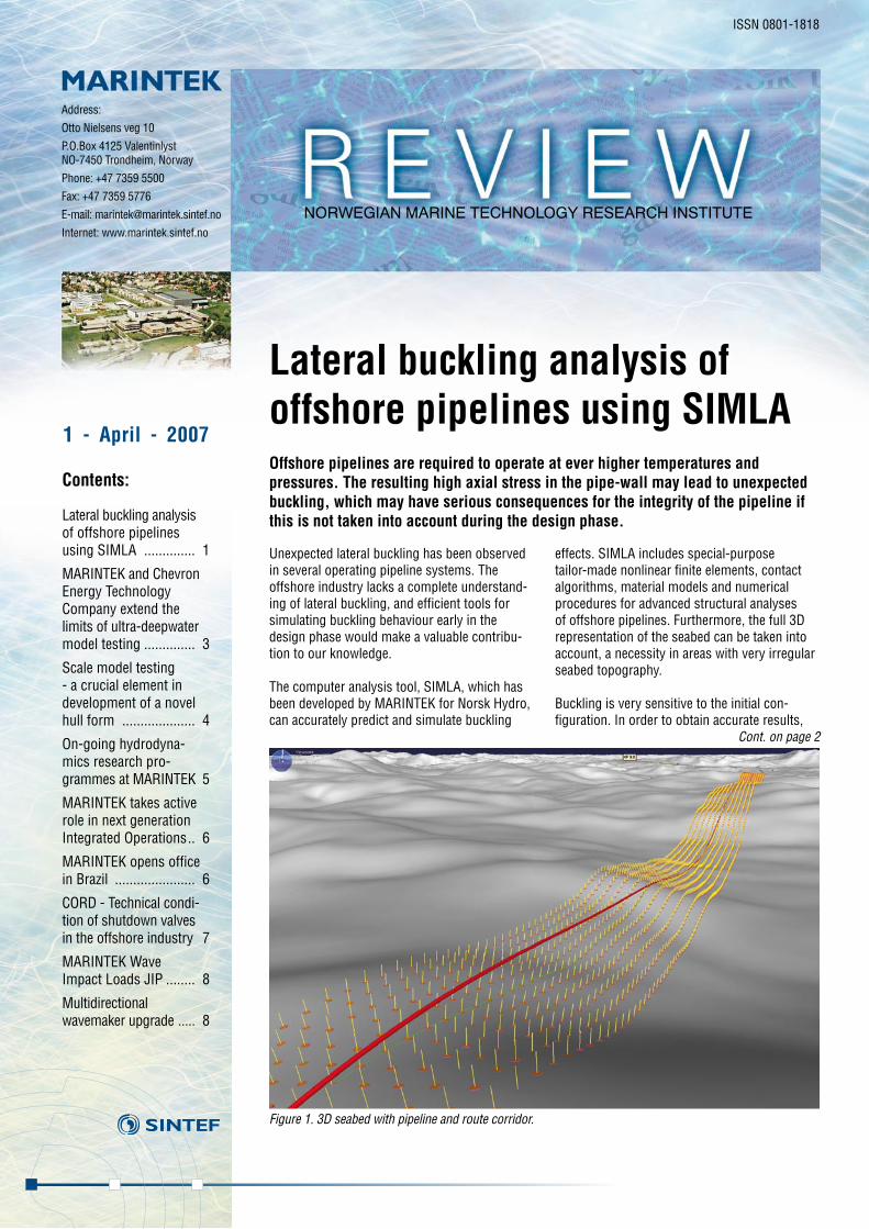
Figure 1. 3D seabed with pipeline and route corridor.
Cont. on page 2

mum lateral displacement is estimated to be 4.6 m, with a maximum axial strain of 0.24%; see Figures 2 and 3.
The SIMLA results were compared with existing results from ANSYS analysis per-formed by Reinertsen Engineering as part of the detailed design process. The buckling shapes, moment and distributions of force are virtually identical. The maximum lateral displacements differed somewhat, being about 9% lower in ANSYS than indicated by SIMLA results; see Figure 3.
In order to enable the ANSYS analysis to be completed within a reasonable time, 8 m ele-ments were used in the ANSYS model. The time required for analysis of an 8 m element model in SIMLA is less than 5 minutes on a 1.8 GHz AMD Opteron PC. In order to obtain more accurate results, an element length of 2 m was also utilised in SIMLA, requiring an elapsed time of 18 minutes. The short analy-sis time indicates that significantly larger sections of the pipe can be analysed in one go with SIMLA without problems.
The existing analysis capabilities of SIMLA enable us to accurately predict and evalu-ate lateral buckling in subsea pipelines. Automatic algorithms and an engineering-friendly input format significantly simplify the pre-processing and model set-up stages. Efficient numerical routines make it possible to analyse long pipeline section with a high degree of accuracy in a matter of minutes.
MARINTEK contacts:[email protected]@marintek.sintef.no
2
the various phases in the life-cycle of the pipeline need to be taken into account in the analysis. SIMLA does this in sequential steps or load cases:
• In the first step, the pipeline is auto-matically placed along the predefined route. This is handled automatically by the AUTOSTART feature in SIMLA. The correct stresses resulting from the route description, seabed, hydrostatic loads and gravity effects are calculated with minimum input from the user.
• Water filling and pressure test are usu-ally then carried out. After full pressure has been obtained, the pipe is de-pres-surised and the water is removed. In SIMLA this is performed by raising and lowering the internal pressure and submerged weight of the pipe.
• Operating or design pressure and the corresponding updated submerged weight are then applied.
• In the final step, the thermal load is applied.
When buckling takes place, the problem is unstable, and a transient dynamic analysis is normally performed to apply the thermal load. SIMLA is able to switch from a static to a dynamic approach within the same analy-sis. This way, the water filling, pressure test and operating loads may be applied statically for the sake of efficiency, leaving the thermal load to be applied dynamically, thus increas-ing the numerical robustness.
In a lateral buckling and stability analysis, interaction between the seabed and the pipe-line are very important. The 3D representa-tion of the seabed ensures accurate results on the basis of geometric effects. Figure 1 visualises an example of a 3D seabed. The green line defines the route centreline and the yellow pins define the surface normals at discrete points. The route corridor grid resolution in both the axial and longitudinal directions is defined by the user.
In addition to the 3D route corridor, the numerical representation of the interaction between the pipe and the soil is also very important. SIMLA makes several numerical pipe/soil interaction models available. The soil stiffness and friction coefficients may individually be defined as functions of dis-placements in the lateral, axial and vertical directions. Both hyperelastic and elastoplas-tic material behaviour may be applied.
In order to verify the buckling analysis capabilities of SIMLA, a 4.5 km section of the Ormen Lange PL-A import line was ana-lysed, using a snake lay route according to the original design produced by Reinertsen Engineering.
The route is relatively flat in this area, with a vertical difference between the start and end of the route section of approximately 22 m.
The seabed was defined with a resolution of 2 m in both axial and lateral directions; see Figure 1 for illustration.
During the pressure test, a pressure of 27.3 MPa was applied. The design pressure was 24.2 MPa, and the design temperature was 31.7º C.
The analysis was defined and run in SIMLA. The results indicate that the pipeline would buckle at two sections, and that the maxi-
Figure 2. Displacement pattern at 100% load.
Figure 3. Lateral displacement vs. route position at 100% load in SIMLA and ANSYS.
Cont. from page 1
Lateral buckling ...
3
Model testing for design verification of floating systems should preferably be done with the full-depth mooring system, if pos-sible. However, model test basins currently can only simulate prototype water depths of up to about 1,000 m at reasonable test scales. This offers a significant challenge, as ultra-deepwater floating systems now reach water depths of 3,000 m. Model tests with truncated mooring system, usually in combination with computer simulations as part of the verification process, are therefore usually necessary. The overall strategy when designing the truncation is to reproduce the vessel motions of the real deepwater system. The aim is thus to reproduce the environmental loads and the most important components of the forces from moorings and risers on the vessel. Certain hydrodyna-mic properties need to be calculated or estimated on the basis of the test results, and a numerical simulation model is used to obtain design loads in the mooring and riser systems.
This “hybrid verification” methodology has been established and validated in the course of a long series of previous develop-ment projects. In an on-going research project MARINTEK and Chevron Energy Technology Company wish to assess the limitations and uncertainties of the hybrid verification scheme.
A deep-draft semi-submersible platform moored by eight taut polyester lines designed for ultra-deep water in the Gulf of Mexico was selected for the case study. In a preliminary purely numerical study, the full-depth system was approximated by three alternative equivalent mooring systems of truncation ratios, in terms of actual basin depth/scaled depth, of 1:3, 1:6 and 1:12, respectively. For the middle truncation ratio, experimental data from previous model test was already available. Time-domain coupled dynamic analysis simulations of the behav-iour of the three different floater systems
were performed. For taut-moored semi-submersibles, the surge-induced pitch is important for the air-gap, and since air-gap is usually taken directly from model tests, it is crucial to model this coupling as correctly as possible over the entire expected offset range. Special emphasis was therefore put on the modeling of the quasi-static surge-pitch (sway-roll) coupling. By manipulating the vertical position of the fairleads, the coupling terms of a truncated mooring system can be modeled to reproduce the full-depth coupling terms well. The moor-ing line profiles of the upper part of the full-depth line and truncated lines are shown in Figure 1. Note that for the shallowest system buoys must be installed on the mooring lines in order to keep them clear of the bottom.
The integration of sophisticated numerical procedures with experiments works well. The coupled dynamic analysis simulations have shown here that the 1:3 and 1:6 truncation ratios reproduce the full-depth system quite well and can be implemented in practice.
MARINTEK and Chevron Energy Technology Company extend the limits of ultra-deepwater model testingMARINTEK and Chevron Energy Technology Company are co-operating in a research project aimed at clarifying the potential and limitations of labora-tory testing of ultra- deepwater floating systems. In such systems, mooring and riser models have to be truncated, and their results must then be com-bined with accurate numerical extrapolation in order to give reliable results (“hybrid verification”).
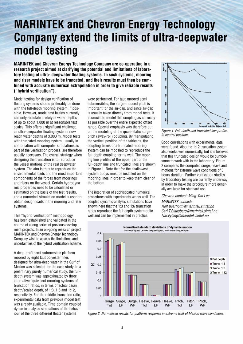
Good correlations with experimental data were found. Also the 1:12 truncation system also works well numerically, but it is believed that this truncated design would be cumber-some to work with in the laboratory. Figure 2 compares the computed surge, heave and motions for extreme wave conditions of 3 hours duration. Further verification studies by laboratory testing are currently underway in order to make the procedure more gener-ally available for standard use.
Chevron contact: Ming-Yao LeeMARINTEK contacts: [email protected]@[email protected]
Figure 1. Full-depth and truncated line profiles in neutral position.
Figure 2. Normalised results for platform response in extreme Gulf of Mexico wave conditions.

4
The above benefits of a cylindrically shaped hull are obvious and the question we are often asked when we present the concept to potential clients, is: “Why has this not been done before?” The fact is that although quite a few attempts have been made, they have all foundered, mainly due to the inabil-ity to obtain satisfactory motion characteris-tics. On this background, Sevan Marine has completed a comprehensive development programme with the goal of finding a suit-able geometrical shape for the unit. During the process of development of this novel hull form, model tests were used in combination with state-of-the-art computa-tional tools. Model testing was then used as an important tool for developing the concept, calibrating the theoretical models and verify-ing the results. As of March 2007, the Sevan hull has been through a total of six different test setups. The first series of tests were carried out in 2002 and the latest in March 2007. All were performed in the MARINTEK Ocean Basin. A total of more than 200 differ-ent tests have been carried out, focusing on:• Wave-induced motions and accelera-
tions• Mooring and riser forces and responses• Relative motions and green water
• Slamming loads. • Thrusters and DP system performance• Towing performance.
We have also used model tests for particular studies of behaviour with respect to focused problem areas such as vortex-induced vibrations (VIV) and Mathieu instability, and we are confident that with the current geo-metrical shape we can avoid these effects.
The one million barrel storage unit has been tested in a lot of seastates ranging over
Scale model testing - a crucial element in development of a novel hull formThe idea of creating a floating unit capable of being moored in a fixed orienta-tion even in the harshest environments was the driving force behind Sevan Marine’s development of a cylindrical hull. This hull form offers significant bene- fits in comparison with ship-shaped or semisubmersible floaters. These include the elimination of the need for turret and swivel system to allow for weathervan-ing, reduced fatigue loads from wave-induced forces on the hull, high deckload capacity and stability reserves, significantly reduced piping and cabling run length, and simplified hull construction due to the repeatability round the circle.
wave heights from 2 - 22 m and wave peri-ods 9 - 20 s. Figures 1 and 2 show relative periods, wave peak period to natural pitch and heave periods. We have also performed comparative tests of a Sevan hull and a ship with the same storage capacity exposed to the same environmental forces.
Sevan contacts:Fredrik Major / Jan Aarsnes
MARINTEK contact:[email protected]
Figure 2.
Model testing in the Ocean Basin.
Figure 1.

5
Marine activities in extreme conditions
More and more marine activities are taking place in areas exposed to extreme weather conditions. As marine activity moves north- wards into the arctic, the probability of encountering rapidly changing weather and extreme conditions is increasing. Other marine activities are taking place in areas where vessel manoeuvreability is of critical importance. The effects on vessels under these conditions may consist of dominant non-linear, transient and interacting compo-nents. There is therefore growing need in the marine community for improved tools for more accurate and cost-effective prediction of motions and loads as well as the controllabi-lity of marine vehicles under extreme condi-tions. The primary objective of this on-going research project is to meet these needs.
The project focuses on the development of realistic and accurate numerical methods and models for predicting motions and loads on marine vehicles under extreme wave con-ditions, improving the integration of model testing and numerical tools, and improving methods of model testing and analysing experimental results so that non-linear and transient effects can be identified and quanti-fied. The work focuses primarily on practical tools for engineering use. New nonlinear model-based control systems, using know-ledge obtained from nonlinear hydrodynamic
and propulsion models to increase control system performance under extreme condi-tions, are also being developed. The general goal is a common control system for use in laboratories, numerical tools, simulators and under full-scale conditions.
Theoretical and numerical hydrodynamics
Numerical tools for determining the hydro-dynamic properties and structural response of ships and marine structures are used in all aspects of engineering for the marine environment. There is a need for both practical methods for use in the early design phase and more complex methods to be used in the final verification phase.
The objective of this project is to meet the need for more advanced methods for pre-dicting hydrodynamic forces on ships and marine structures. The project will provide the foundation for the next generation of computational tools for hydrodynamic analy-sis at MARINTEK. The research will focus on the development of robust methods and tools for hydroelastic seakeeping analysis that take wave/current interactions, forward speed and multibody hydrodynamics into account. The project will also work towards the develop-ment of a 3D BEM/FEM domain decomposi-tion method, in which viscous effects can be taken into account in an inner domain.
Traditionally, sea-keeping capability of ships has been evaluated using strip theory. Although this approach has been successful in predict-ing the motions of traditional ship hulls, it has its limitations in predicting local flow behavior in the bow and stern regions which will be important for reliable predictions of added
resistance and global loads. Furthermore, strip theory is valid only for high encounter frequencies and moderate forward speeds. A three-dimensional approach is therefore needed. For long and slender ships, hydro-elastic effects may be important and these can be taken into account by including gen-eralized motion modes in addition to the six rigid body modes. Hydrodynamic interaction effects are important in the analysis of ship-to-ship cargo transfers and in other opera-tions that involve several vessels. Under high waves and current conditions, wave/current interactions are crucial for calculating wave drift forces, and thus for extreme mooring line and riser tensions, on offshore floating platforms. Today we rely on model test data to evaluate the resulting drift forces in waves and current. Accurate numerical prediction tools would therefore be welcome. Normally, viscous effects have been included by means of empirical formulas when the contribu-tion to roll damping is being estimated. The usefulness of existing empirical formulations may be questioned when applied to modern hull forms. Viscous effects are also impor-tant for the determination of the efficiency of rudders and propulsors. This has motivated a domain decomposition formulation in which a volume discretization method is used for the solution of the Navier-Stokes equations is used in an inner domain close to the vessel, while the flow in the outer domain is assumed to be described by potential theory and is calculated by a boundary element formulation. A volume discretiza-tion method will result in a large number of unknowns and a heavy computational effort. Using a domain decomposition method will allow for a more efficient formulation, since the volume decomposition method is limited to a smaller volume close to the ship, where viscous effects are important.
MARINTEK contacts:[email protected]@[email protected]@marintek.sintef.no
On-going hydrodynamics research programmes at MARINTEKIn the course of the past year, MARINTEK has initiated several research programmes on various topics in marine hydrodynamics. These include two three-year strategic research programmes funded by the Research Council of Norway. The first focuses on improving prediction
The research programme covers a large span of activities within the field of marine hydrodynamics and automatic control in extreme conditions.
methods for the behaviour of marine structures in extreme conditions, while the second lays the foundation for the next generation of seakeeping and hydrodynamic analysis tools to be developed by MARINTEK.

6
The IO Centre has been named a Centre for Research based Innovation (CRI) by the Research Council of Norway, with public-sector support of NOK 10 million a year for five years from 2006 (optionally extendable to eight years).
The major industrial contributions to the Centre come from Statoil, Norsk Hydro, Total, Gaz de France, Petoro, Shell, Conoco-Phillips, Kongsberg Maritime, IBM, Aker Kværner and FMC Technologies. The IO Centre has an annual budget of around 40 MNOK.
The activities of the centre are organized in four major programmes:
1. Drilling and well construction2. Reservoir management and production
optimization3. Operation and maintenance4. Integration across disciplines.
Programme no. 3 is headed by MARINTEK and comprises three projects:
1. A generic framework for predictive maintenance control
- Data validation, estimation and pre- diction
- Physical degradation – estimation and prediction
- Lifetime and performance prediction.
2. Condition monitoring of oil and gas facilities
- Identify those aspects of oil and gas production for which next-generation CM offers the most potential for added value in IO
- Determine the corresponding facilities and produced/injected media relevant to the above-mentioned areas
- Map/identify the most important decisions to be taken in monitoring and maintaining these facilities
- Develop and test methods for aggre- gating information to support these decisions.
3. Integrated Planning - Map the IPL process as defined by
industry - Design and build a concurrent plan-
ning facility at MARINTEK - Develop an implementation and
session guideline for conducting planning sessions
- Define the tools required for IPL and Integrated Logistic Support planning, including data-sharing architecture
- Define and start a PhD programme in IPL
- Draw up KPIs and IPL management guidelines
The Centre will comprise • 25-30 research scientists from NTNU/
SINTEF/IFE• 15 -20 professors at NTNU• 30 PhD students (over a five-year
period)• Five experts from international leading
universities • Personnel from the industrial partners.
The teams will work in a distributed virtual environment, with participation from NTNU, SINTEF and IFE, together with the industrial partners and the international university partners.
MARINTEK contact: [email protected]
MARINTEK takes active role in next generation Integrated OperationsIn collaboration with a number of major international oil companies and service industries, NTNU, SINTEF and IFE have established a Centre for e-Field and Integrated Operation (IO). The Centre is cooperating with the Universities of Stanford, Carnegie-Mellon, Delft and Kyoto.
The Centre aims to be a major international provider of knowledge and technology in Integrated Operation in the oil and gas sector.
The Brazilian market is experiencing tre-mendous growth, with the development of several fields in ultra-deep water, a situation that offers interesting opportunities for all of MARINTEK’s areas of expertise.
MARINTEK is now establishing a subsidiary in Rio de Janeiro, with the aim of signing agreements and establishing cooperation with universities, research institutions and R&D companies, and to further develop our relationships with existing clients.
The subsidiary will be called MARINTEK do Brasil, and the office will be located in Torre Rio Sul. The director of MARINTEK do Brazil is Svein I. Karlsen, who has many
MARINTEK opens office in BrazilMARINTEK has been active in the Brazilian market for more than 30 years, assisting the booming shipbuilding industry in the late 70s, and then the growing offshore oil industry, most importantly represented by Petrobras. For the past 10 years, Petrobras has been one of our major clients. In addition to a long list of verification model tests, several research programmes have been carried out in close cooperation with the company.
7
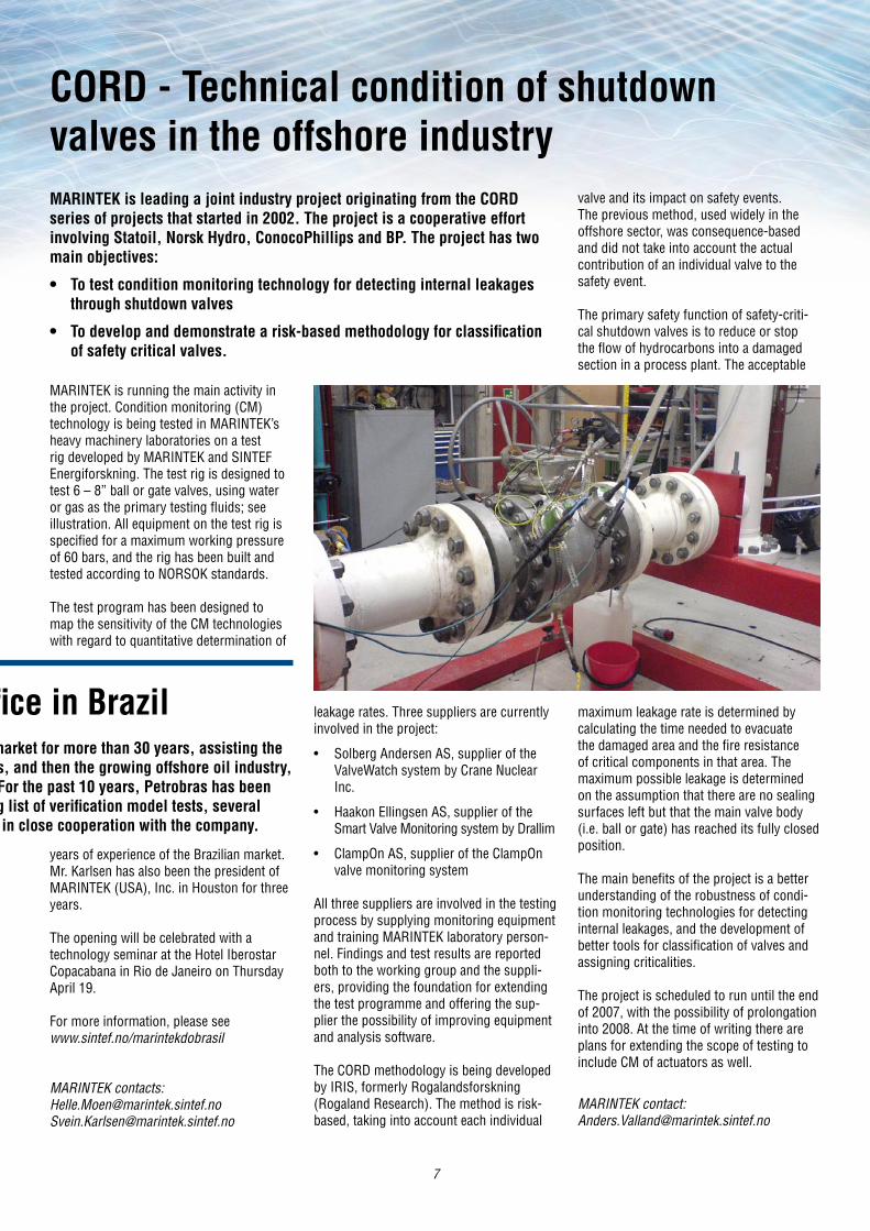
MARINTEK is running the main activity in the project. Condition monitoring (CM) technology is being tested in MARINTEK’s heavy machinery laboratories on a test rig developed by MARINTEK and SINTEF Energiforskning. The test rig is designed to test 6 – 8” ball or gate valves, using water or gas as the primary testing fluids; see illustration. All equipment on the test rig is specified for a maximum working pressure of 60 bars, and the rig has been built and tested according to NORSOK standards.
The test program has been designed to map the sensitivity of the CM technologies with regard to quantitative determination of
CORD - Technical condition of shutdown valves in the offshore industryMARINTEK is leading a joint industry project originating from the CORD series of projects that started in 2002. The project is a cooperative effort involving Statoil, Norsk Hydro, ConocoPhillips and BP. The project has two main objectives:
• To test condition monitoring technology for detecting internal leakages through shutdown valves
• To develop and demonstrate a risk-based methodology for classification of safety critical valves.
valve and its impact on safety events. The previous method, used widely in the offshore sector, was consequence-based and did not take into account the actual contribution of an individual valve to the safety event.
The primary safety function of safety-criti-cal shutdown valves is to reduce or stop the flow of hydrocarbons into a damaged section in a process plant. The acceptable
leakage rates. Three suppliers are currently involved in the project:
• Solberg Andersen AS, supplier of the ValveWatch system by Crane Nuclear Inc.
• Haakon Ellingsen AS, supplier of the Smart Valve Monitoring system by Drallim
• ClampOn AS, supplier of the ClampOn valve monitoring system
All three suppliers are involved in the testing process by supplying monitoring equipment and training MARINTEK laboratory person-nel. Findings and test results are reported both to the working group and the suppli-ers, providing the foundation for extending the test programme and offering the sup-plier the possibility of improving equipment and analysis software.
The CORD methodology is being developed by IRIS, formerly Rogalandsforskning (Rogaland Research). The method is risk-based, taking into account each individual
years of experience of the Brazilian market. Mr. Karlsen has also been the president of MARINTEK (USA), Inc. in Houston for three years. The opening will be celebrated with a technology seminar at the Hotel Iberostar Copacabana in Rio de Janeiro on Thursday April 19.
For more information, please see www.sintef.no/marintekdobrasil
MARINTEK contacts: [email protected] [email protected]
MARINTEK opens office in BrazilMARINTEK has been active in the Brazilian market for more than 30 years, assisting the booming shipbuilding industry in the late 70s, and then the growing offshore oil industry, most importantly represented by Petrobras. For the past 10 years, Petrobras has been one of our major clients. In addition to a long list of verification model tests, several research programmes have been carried out in close cooperation with the company.
maximum leakage rate is determined by calculating the time needed to evacuate the damaged area and the fire resistance of critical components in that area. The maximum possible leakage is determined on the assumption that there are no sealing surfaces left but that the main valve body (i.e. ball or gate) has reached its fully closed position.
The main benefits of the project is a better understanding of the robustness of condi-tion monitoring technologies for detecting internal leakages, and the development of better tools for classification of valves and assigning criticalities.
The project is scheduled to run until the end of 2007, with the possibility of prolongation into 2008. At the time of writing there are plans for extending the scope of testing to include CM of actuators as well.
MARINTEK contact: [email protected]
8
In the wake of constant developments in field data and sea-state specifications, our clients’ requests have become more demanding with respect to testing in multidirectional or bi-directional sea states. The upgrade enables us to meet this need. MARINTEK was one of the first major laboratories in the world to use multidirec-tional waves in offshore model testing, and we have acquired significant experience and expertise in this field in the course of 25 years. This is now being taken a step for-ward, and we are now even better prepared for future challenges.
Multidirectional wavemaker upgradeMARINTEK’s 62.5 m long multidi-rectional wave generator, installed in the 80 x 50 m Ocean Basin in 1981, has recently been upgraded. New control systems and hydraulic actuators have been installed for each of the 144 individual flaps. The upgrade provides better perform-ance, i.e. larger waves over a wider area of the basin, more directional flexibility, and makes for a more robust and reliable system. The multiflap wavemaker is installed along
one long side of the Ocean Basin, while a large double-flap wavemaker fills one of the 50 m “short” sides. The use of hydraulic actuators in both systems is regarded as an advantage, since they are connected to the same pump system. In combination, they can simulate a wide variety of complex wave conditions, and currents can also be added. Both wavemakers are designed with dry back sides. They are also connected to the same wave-generation control software.
MARINTEK contacts:[email protected]@marintek.sintef.no
MARINTEK Wave Impact Loads JIP
During the past few years, MARINTEK has built up a significant degree of expertise and performed a wide range of develop-ment projects on these and related topics. These include the WaveLand JIPs as well as several other research projects on waves and slamming. Plans for further work, in which previous findings are combined into practical procedures and tools, have now finally been realized through the new JIP, which was launched in February 2007. The focus is on applications in practical design, while still based on front-line knowledge and basic physics.
From a theoretical point of view, the study of hydrodynamic impacts of extreme and
steep waves is still in the early stages of development, due to the very complex physical mechanisms involved. Model testing therefore plays, and will continue to play, a critical role in the final estimation of design loads. The approach described therefore continues to make use of carefully carried out experiments, now in combina-tion with improved theoretical tools, leading to more accurate and robust estimates during the early stages of the process and in final design:
• Applications on jackets, semi/TLP/spar, buoys, FPSO
• Nonlinear irregular wave description• Nonlinear & current-induced wave
amplification caused by large-volume hulls
• Efficient, improved and validated non-linear software for wave-on-deck loads
• Statistical correlations between random wave characteristics and impacts
• Basic physics, variability and scaling observed from slamming experiments
• Improved and more efficient procedures in model test impact studies
• Guidelines and recommendations.
A growing amount of attention is being paid to designing offshore installa-tions to withstand impacts in extreme weather. Impact and slamming loads imposed on platform decks and bow structures by heavy waves are of par-ticular interest. MARINTEK has recently started a new two-year Joint Industry Project (JIP) with the aim of identifying critical wave parameters and of establishing robust and accurate engineering prediction tools for the result-ing loads on structures.
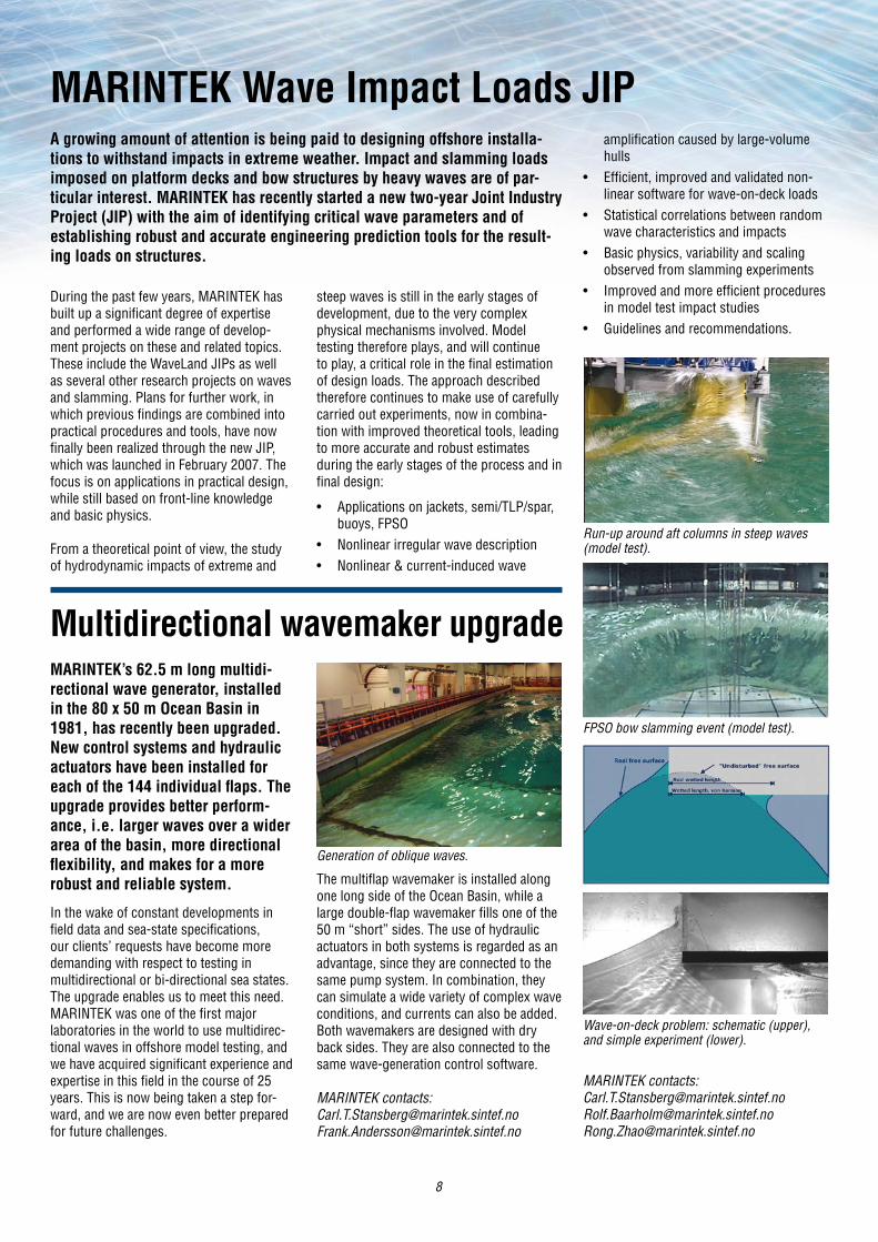
Generation of oblique waves.
Run-up around aft columns in steep waves (model test).
Wave-on-deck problem: schematic (upper), and simple experiment (lower).
MARINTEK contacts: [email protected]@[email protected]
FPSO bow slamming event (model test).