lasers and laser spectroscopy - home | · pdf filecomplete one round-trip of the ... 340 . 9...
TRANSCRIPT

COPIES
K.. Hedman, 1., Johans'-:lJl.. 96-) Electron Spectros.:",=,," , STudies by Means at £
:1". Berlin. '-0 J. Molecular LASERS AND LASER
SPECTROSCOPY
General discussion of lasers
General features and properties
The word 'laser' is an acronym derived from 'light amplification by the stimulated emission of radiation'. If the light concerned is in the microwave region then the alternative acronym 'maser' is often used. Although the first such device to be constructed was the ammonia maser in 1954 it is the lasers made subsequently which operate in the infrared, visible or ultraviolet regions of the spectrum which have made a greater impact.
In Section 2.2 we saw that emission of radiation by an excited atom or molecule M* may be by a spontaneous (Equation 2.4) or by an induced, or stimulated, process
M* + h6 ~ M + 2h6 (9.1)
as in Equation (2.5). Laser radiation is emitted entirely by the process of stimulated emission, unlike the more
conventional sources of radiation discussed in Chapter 3, which emit through a spontaneous process.
For induced emission from the upper energy level n of the two-level system in Figure 2.2(a) to dominate absorption (Equation 2.3) there must be a population inversion between the two levels, that is N > N where N; refers to the population of state i. To disturb the n m
normal Boltzmann population distribution (Equation 2.11), in which N < Nm , requires an n
input ofenergy. The process by which such a population inversion is brought about is known as pumping. A system, which may be gaseous, solid or liquid and in which a population inversion has been created is referred to as an active medium. According to Equation (9.1) the active medium is capable ofacting as an amplifier of radiation fal1ing on it. The equation shows that, for every photon entering the active medium, two photons are emitted from it.
To make an oscillator from an amplifier requires, in the language of electronics, positive feedback. In lasers this is provided by the active medium being between two mirrors, both of them highly reflecting but one rather less so in order to al10w some of the stimulated radiation to leak out and form the laser beam. The region bounded by the mirrors is cal1ed the laser cavity. Various mirror systems are used but that shown in Figure 9.1, consisting of
337

i
,
I
338 9 LASERS AND LASER SPECTROSCOPY
f Jd.
Figure 9.1 Laser cavity with two plane mirrors
two plane mirrors a distance d apart, is one of the simplest. The mirror separation must ~
integral number of half-wavelengths, nA12, apart, necessitating extremely acc alignment. The resonant frequency v of the cavity is then given by
nc v = 2d
Worked example 9.1
Question, A laser cavity is 10.339 96 cm long and is operating at a wavelength C': 533.647 8 nm. How many half-wavelengths are there along the length of the cavity? By ho\\ much would the length have to be changed to increase this number by one? What consequences does this result have for the tuning of such a cavity? How long does it take for the radiation to complete one round-trip of the cavity (to four significant figures)?
Answer. Since wavelength Aand frequency v are related by
C = VA
Equation (9.2) gives
),=:_2d v n
2d 2 x 10.339 96 x 107 nm .'. n=--;
A 533,6478 nm
= 3.875 200 x 105
Increasing n by one gives
n = 3.875 210 x 105
, d = nA = 3.875 210 x 105 x 533.6478 x 10-7 cm . . 2 2
= 10.33999 cm
Therefore :~,;
tune the -:.:' ~":'.. one of t):,; :-:',:
One r(',~:-,":'
The rcfk-:ll: and lo\\' ,b:':c.
specific Lh:'~ \
highly rd.c~::l
to emergc .:-- 1
Photon"':' Those thJ: -::-1
flux to reJ-::-, J
active mec:~1
Laser uc:J
1. DirecT" ':..l
parallel. '.\ mirror" 0
2. A1o/l(I,,; "'.J a ga~C'(Il-~
range (\: : the la~c~
wa\ ekr:s:1
3. Brigli":d unit ~(\;:j
reason :0 0,5 n:\\
4. Coli, i',':, electr(\:Tl. generJ .. coherC'n-: CohercTJ' as In :l1e

339 9.1 GENERAL DISCUSSION OF LASERS
Therefore the cavity has been increased in length by 0.000 03 cm = 0.3 ~m. This means that to tune the cavity to a half wavelength of the radiation requires an extremely accurate movement of one of the mirrors forming the cavity.
One round-trip of the cavity covers a distance of 20.680 cm
20.680 cm time taken
2.997 9 x 1010 cm s-1 = 6.898 X 10⁻¹⁰ s
The reflecting surfaces of the mirrors are specially coated, with alternate layers of high and low dielectric materials such as Ti02 and SiO, to give almost total reflection at the specific laser wavelength. The usual aluminium, silver or gold coatings are not sufficiently highly reflecting. One of the mirrors is coated so as to allow 1 to 10 per cent of the radiation to emerge as the laser beam.
Photons of energy hc'V are generated initially in the cavity through spontaneous emission. Those that strike the cavity mirrors at 90° are retained within the cavity causing the photon
a wawlength flux to reach a level which is sufficiently high to cause stimulated emission to occur, and the Ie cavity') By h~ active medium is said to lase. liar consequen.:e.s Laser radiation has four very remarkable properties: Ilr' the radiation TO
I. Directionality. The laser beam emerging from the output mirror of the cavity is highly parallel, which is a consequence of the strict requirements for the alignment of the cavity mirrors. Divergence of the beam is typically a few milliradians.
2. Monochromaticity. If the energy levels nand m in Figure 2.2(a) are sharp, as they are in a gaseous active medium, the Planck relation of Equation (2.2) limits the wavelength range of the radiation. However, whatever the nature of the active medium, the fact that the laser cavity is resonant only for the frequencies given by Equation (9.2) limits the wavelength range.
3. Brightness. This is defined as the power emitted per unit area of the output mirror per unit solid angle and is extremely high compared with that of a conventional source. The reason for this is that, although the power may be only modest, as in, for example, a 0.5 mW helium-neon gas laser, the solid angle over which it is distributed is very small.
4. Coherence. Conventional sources of radiation are incoherent, which means that the electromagnetic waves associated with any two photons of the same wavelength are, in general, out of phase. The coherence of laser radiation is both temporal and spatial, the coherence lasting for a relatively long time and extending over a relatively large distance. Coherence of laser radiation is responsible for its use as a source of intense local heating, as in metal cutting and welding, and for holography.
340 9 LASERS AND LASER SPECTROSCOPY
9.1.2 Methods ofobtaining population inversion
Equation (9.1) may give the impression that in the stimulated emission process w;;:
getting something for nothing-putting in one quantum of energy and getting out two process does involve an amplification of the radiation (hence the 'light amplification' \\appears in the acronym) but energy has to be put into the system to excite M to M* SQ
in the overall process of M being excited and then undergoing stimulated emission. th~
no energy gain. Not only is there no energy gain but the efficiency of the overall pre-.:: is very low. For example, a nitrogen gas laser has an efficiency of less than 0.1 per ~.
and a semiconductor (diode) laser, one of the best in this respect, has an efficiency of a...;""'. 30 per cent.
Before we look at the various methods of pumping we shall consider the types of en~_
level scheme encountered in lasing materials. So far we have thought of the stimulated emission occurring in a lasing material as be
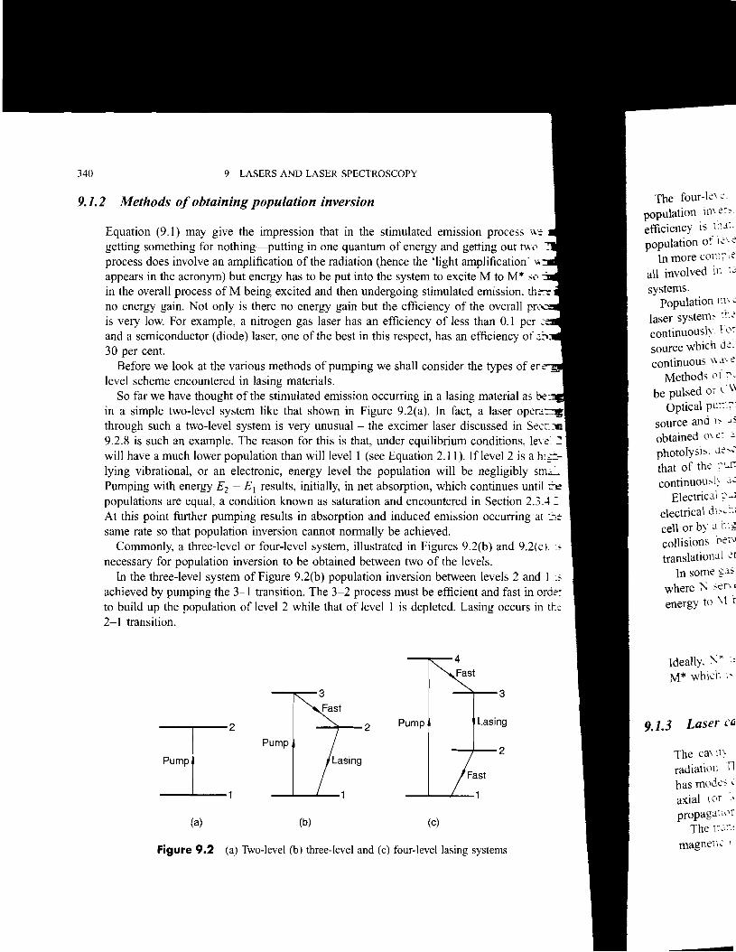
in a simple two-level system like that shown in Figure 9.2(a). In fact, a laser opera~
through such a two-level system is very unusual - the excimer laser discussed in Sec":-' 9.2.8 is such an example. The reason for this is that, under equilibrium conditions, lew: ~
will have a much lower population than will level 1 (see Equation 2.11). If level 2 is a hi~lying vibrational, or an electronic, energy level the population will be negligibly sm'="'::' Pumping with energy E2 - E[ results, initially, in net absorption, which continues until =-~
populations are equal, a condition known as saturation and encountered in Section 2.3A :: At this point further pumping results in absorption and induced emission occurring at D~
same rate so that population inversion cannot normally be achieved. Commonly, a three-level or four-level system, illustrated in Figures 9.2(b) and 9.2(CI.'
necessary for population inversion to be obtained between two of the levels. In the three-level system of Figure 9.2(b) population inversion between levels 2 and 1 :,
achieved by pumping the 3-1 transition. The 3-2 process must be efficient and fast in ordc:to build up the population of level 2 while that of level 1 is depleted. Lasing occurs in t\:;:
2-1 transition.
It 4 Fast
R 3 4 3 Fast
Pump Lasing4 2
Pump J 2--r2
~ 1
(a) (b) (e)
Figure 9.2 (a) Two-level (b) three-level and (c) four-level lasing systems
The four-k\;:. population in\ ;:~':
efficiency is tllJ:. population of i;:\ ~
In more com;";: all involved in :.:: systems.
population tn\ ~
laser system, ti-.;: continuously. Fl'r source which d;:', continuous \\ .1\ ;:
Methods 01 :'L
be pulsed or L\\
Optical puc::'] source and l' j, obtained 0\;:; .::
photolysis. <1;:<"
that of the ;"~I1
continuou,l; .::~
Electric al :,...I
electrical dl,~r.,
cell or by at,.~
collisions be,,' translational ;:1
In some ~.1s
where 1': sen, energy to \ \ t
Ideally. ~ x :,
M* which l'
9.1.3 Laser C~
The ca\ It\ ,
radiation 1l has mode- .: axial ((,r '.• propagatl"f
The tf.1::' magnetl~ I

mIssion process \\e
md getting out two ~t amplification' \~ excite M to M* so I1ated emission. there ,- of the overall pre less than 0.1 per .:-_
>an efficiency of .
ISing material as raet. a laser opera" . discussed in Sect IDJ conditions. le\ eJ 2 t I. Iflevel 2 is a hIgjl-1 be negligibly srn.al.
~h continues until ~ ~ in Section 2.3.~": .ion occurring at ti:r
9.2(b) and 9.2( CI. ::i
le\els.
~ levels 2 and I 'S
rot and fast in or~
.asing occurs in ~
>t
1-3
~laSing
L 2
1St
-stems
9.1 GENERAL DISCUSSION OF LASERS 341
The four-level system in Figure 9.2(c) is even more efficient in the creation of a population inversion, in this case between levels 3 and 2. The reason for the greater efficiency is that, not only is level 3 populated through the fast 4-3 process, but the population of level 2 is rapidly depleted by the fast 2-1 process.
In more complex systems there may be more levels between 4 and 3 and between 2 and I, all involved in fast processes to lower levels, but they are still referred to as four-level systems.
Population inversion is difficult not only to achieve but also to maintain. Indeed, for many laser systems there is no method of pumping which will maintain a population inversion continuously. For such systems inversion can be brought about only by means of a pumping source which delivers short, high-energy pulses. The result is a pulsed laser as opposed to a continuous wave, or Cw, laser which operates continuously.
Methods of pumping, irrespective of the type of level system and of whether lasing is to be pulsed or CW, fall into two general categories-optical and electrical pumping.
Optical pumping involves the transfer of energy to the system from a high-intensity light source and is used particularly for solid and liquid lasers. A very high photon flux can be obtained over a short period of time from inert gas f1ashlamps of the type used in flash photolysis, described in Section 3.5.4. The result is a pulsed laser, the repetition rate being that of the pumping source. CW optical pumping may be achieved in some lasers by a continuously acting tungsten-iodine, krypton, or high-pressure mercury arc lamp.
Electrical pumping is used for gas and semiconductor lasers. In a gas laser this involves an electrical discharge in the gas which may be induced by microwave radiation outside the gas cell or by a high voltage across electrodes inside the cell. The pumping is achieved through collisions between the gaseous atoms or molecules and electrons produced with high translational energy in the discharge.
In some gas lasers it is preferable to use a mixture of the lasing gas M and a second gas N, where N serves only to be excited to N* by collisions with electrons and to transfer this energy to M by further collisions:
M + N* --+ M* + N (9.3)
Ideally, N* is a long-lived, metastable state with an energy similar to that of the level of M* which is being pumped.
9.1.3 Laser cavity modes
The cavity of a laser may resonate in various ways during the process of generation of radiation. The cavity, which we can regard as a rectangular box with a square cross-section, has modes of oscillation, referred to as cavity modes, which are of two types, transverse and axial (or longitudinal). These are, respectively, normal to and along the direction of propagation of the laser radiation.
The transverse modes are labelled TEMmb where TEM stands for transverse electric and magnetic (field): m and e are integers that refer to the number of vertical and horizontal

9.1.4 Q-switching
Fig
a much shone: ! giant pulse \.1:1
simple in pnr.':l A pockets .:c'
refracting) \\ hc' passes throu:;r, pure crysta!im potassium lilt:) (KDzPO-\. KJ)'
Figure 9..+ s cavity is pl::me circularly pl'lJ. of circular pl'] plane-polanzc
polarizer, IllS from the l'Utp
length of lhe
Q-switching IS J.D time by pre\ennr cavity mirror~ C laser action bUl;j
allowed to in.:re' Since the pu1se \
where ~ v is the lJ.S defined in EqUJ.l: operation resulb U
related to the enefj
(9~
(9.5)
c ~v = 2d
v Q= ~v
\ "," /I 1\ , \ , \ I \ If'... Threshold
9 LASERS AND LASER SPECTROSCOPY
Gain
t l
Output
nodal planes of the oscillation, respectively. Usually it is preferable to use only the TE\{,•• mode, which produces a laser beam with a gaussian intensity distribution (see Figure': 5", nonnal to the direction of propagation.
The variety of possible axial modes is generally of greater consequence. The vanl'~
frequencies possible are given by Equation (9.2) so that the separation ~v of the axial m0d.3 is given by
v--
Figure 9.3 Doppler limited laser line with twelve axial modes within the line width
For a cavity length of, for example, 50 cm the axial mode separation is (0.01 cm- I
).
In practice the laser can operate only when n, in Equation (9.2), takes values such that th.: corresponding resonant frequency v lies within the line width of the transition between tb.: two energy levels involved. If the active medium is a gas this line width may be the Dopple line width (see Section 2.3.2). Figure 9.3 shows a case where there are twelve axial modC'" within the Doppler profile. The number of modes in the actual laser beam depends on ho\' much radiation is allowed to leak out of the cavity. In the example in Figure 9.3 the outpu: level has been adjusted so that the so-called threshold condition allows six axial modes ir. the beam. The gain, or the degree of amplification, achieved in the laser is a measure of the intensity.
It is clear from Figure 9.3 that the laser line width for a single axial mode is much less than the Doppler line width. Nonnally a laser will operate in multimode fashion but for many purposes, for example in high-resolution spectroscopy using a laser source, it is desirable that the laser be made to operate in a single mode. One possible way of achieving this is clear from Equation (9.4). By making the cavity length d sufficiently short that only one axial mode lies within the Doppler profile, single-mode operation results. This method is applicable mostly to infrared lasers where the Doppler line width, of the order of 100 MHz, is relatively small. Whatever method is used for single-mode operation there is a considerable loss of laser power compared with multimode operation.
The quality factor Q of a laser cavity is defined as
342

-Threshold
~ 'ithin the line width
, to use only the IE.\ ibution (see Figure 2.5'
paration IS
~ values such that ~
transition between tbe b may be the Dopple: e twelve axial mod~
earn depends on hC"14 Figure 9.3 the Outpuc "5 six axial modes Il:
r is a measure of the
[ mode is much less ode fashion but [C'r
I laser source, it IS
Ie way of achieving ntly short that onl~ ~ults. This method 1. of the order of )peration there is a
9.1 GENERAL DISCUSSION OF LASERS 343
where Llv is the laser line width. Q can be regarded as the 'resolving power' of the cavity, as defined in Equation (3.3) for the dispersing element of a spectrometer. Single-mode operation results in a smaller Ll v and, therefore, a higher Q than multimode operation. Q is related to the energy E stored in the cavity and the energy E1 allowed to leak out in time 1 byc
Q = 2nvEcl (9.6)E1
Q-switching is an operation whereby the Q of a laser cavity is reduced for a short period of time by preventing the radiation from being reflected backwards and forwards between the cavity mirrors. During this time the population of the upper of the two levels involved in laser action builds up to a much higher value than it would be if Q remained high. Then Q is allowed to increase rapidly and the cycle is repeated, resulting in very short laser pulses. Since the pulse duration Lll is related to the pulse power Pp and energy Ep by
Ep (9.7)Pp = Lll
a much shorter pulse leads to a large increase in power. The resulting pulse is referred to as a giant pulse. Various methods of Q-switching are used. A rotating mirror in the laser cavity is simple in principle but a Pockels cell is used more often.
A Pockels cell is made from an electro-optic material which becomes birefringent (doubly refracting) when a voltage is applied across it. The result is that, if plane polarized radiation passes through the material, it emerges, in general, elliptically polarized. Such materials are pure crystalline ammonium dihydrogen phosphate [(NH4)H2P04, abbreviated to ADP], potassium dihydrogen phosphate (KH2P04, KDP), and potassium dideuterium phosphate (KD2P04, KD*P). All may be used in a laser operating in the visible region.
Figure 9.4 shows how a Pockels cell may be used in a laser cavity. The radiation in the cavity is plane-polarized by the polarizer P and passes to the Pockels cell, where it becomes circularly polarized when the voltage is applied. On reflection at the mirror M 1 the direction of circular polarization is reversed. On passing through the Pockels cell a second time it is plane-polarized but at 90° to the original plane and, therefore, is not transmitted by the polarizer. It is only when the voltage is switched off that a Q-switched giant pulse emerges from the output mirror M2. The timing of the voltage switching determines the power and length of the output pulses.
( M J-Mirror M1 -v +V Polarizer P Mirror M2
(9.51 Figure 9.4 Use of Pockels cell (PC) in a laser cavity to produce Q-switching

I
.
344 9 LASERS AND LASER SPECTROSCOPY
9.1.5 Mode locking
Although Q-switching produces shortened pulses, typically 10-200 ns long, if we reqc~
pulses in the picosecond (10- 12 s) or femtosecond (10- 15 s) range the technique of m~ locking may be used. This technique is applicable only to multimode operation ofa laser r,': involves exciting many axial cavity modes but with the correct amplitude and ph.l-~
relationship. The amplitudes and phases of the various modes are normally quite randorL Each axial mode has its own characteristic pattern of nodal planes and the frequenc:.
separation ~v between modes is given by Equation (9.4). If the radiation in the cavity can tc modulated at a frequency of c/2d then the modes of the cavity are locked both in amplituo.: and phase since tp the time for the radiation to make one round-trip of the cavity (a distan.::;; 2d), is given by
2d t = (9.:'. r C
The result is that, for the case of a cavity operated with, say, seven modes, the output is like that in Figure 9.5 when the cavity is mode locked. Only the modes which have a node at one end of the cavity are output from the laser and all others are suppressed.
The width ~t of the pulse at half-height is given by
2n (9.91~t = (2N + I)~v
where (2N + I) is the number of axial modes excited and ~v is their frequency separation. One method of mode locking a visible laser is by placing an acoustic modulator in the
cavity and driving it at a frequency of c/2d. An important consequence of shortening a laser pulse is that the line width is increased as
a result of the uncertainty principle as stated in Equation (1.16). When the width of the pulse is very small there is difficulty in measuring the energy precisely because of the rather small number of wavelengths in the pulse. For example, for a pulse width of 40 ps there is a frequency spread of the laser, given approximately by (2n~t)-1, of about 4.0 GHz (0.13 cm- I
).
Pulse lengths of < 100 fs (1 femtosecond = 10- 15 s) have been achieved by mode locking.
Output power
Time,t-
Figure 9.5 Suppression of five out of seven axial cavity modes by mode locking
Harmonic.
In the conte': electric field E
by
In fact, thb e-:.
in E
where P ;' " effects dti;; " because t>';;:· the ve~:··::
importan: The nu;:
where .~,
the radial:' twice th;; 1
called fr;;J Equatlc'C
WorkE
QI" .:;. frcc: •. ~·
gcL;;:-J
.~I:' .'.'
\\ ''':~ ~
-

I() ns long, if we reg e the technique of m":i
~ operation ofa laser t amplitude and ph 10rmally quite random. lIles and the frequeoc-, ~on in the cavity can . eked both in ampJi .fthe cavity (a dis~
des. the output is leU ch have a node at one ;ed.
equency separanor:. ic modulator in t~
idth is increased JS
~ width of the pulX' of the rather smalJ f .f0 ps there is a f about 4.0 GHz
9.1 GENERAL DISCUSSION OF LASERS 345
Harmonic generation
In the context of discussion of the Raman effect, Equation (5.43) relates the oscillating electric field E of the incident radiation, the induced electric dipole Jl and the polarizability a by
Jl = aE (9.10)
In fact, this equation is only approximate and Jl should really be expressed as a power series in E
Jl = Jl(l) + Jl(2) + Jl(3) + ... (9.11)
= aE +tpE.E +i rE .E .E + ...
where P is known as the hyperpolarizability and 'I the second hyperpolarizability. Any effects due to the second (or higher) terms in the series are referred to as non-linear effects because they arise from terms which are non-linear in E. These effects are usually small but the very high power, and therefore E, characteristic of laser radiation causes them to be important.
The magnitude of the oscillating electric field is given by
E = A sin2nvt (9.12)
where A is the amplitude and v the frequency. Since
E2 = A2(sin2nvt)2 = tA2(l - cos2n2vt) (9.13)
the radiation scattered by the sample contains, due to the Jl(2) term, some radiation with twice the frequency (or half the wavelength) of the incident radiation. The phenomenon is called frequency doubling or second harmonic generation. In general, higher-order terms in Equation (9.11) can result in third, fourth, etc., harmonic generation.
Iby mode lockina Worked example 9.2
Question. Show that the third tenn in Equation (9.11) results in the generation ofradiation of frequency 3v when radiation of frequency v is incident on a crystal capable of third hannonic generation.
Answer. The third tenn in equation (9.11) involves the cube of the oscillating electric field which (cf. Equation 9.13) is given by
e locking £3 = A3(sin 2rcvti

346 9 LASERS AND LASER SPECTROSCOPY
But, in general, sin3 e= ~ sin e- ±sin 3e ~T
I,
Because the second term in the brackets contains 3v in the sine function, radiation at 1
frequency which is three times that of the incident radiation is generated. This is referred to ~
third harmonic generation. The first term in brackets indicates that some radiation ofunchangc': frequency also results.
.'. E3 =A3(~sin2TCvt-~sin2TC3vt)
~A:
.jT1,
\ Energy
-
There are several pure crystalline materials which may be used for frequency doubi~
Examples are ADP, KDP and KD*P, mentioned in Section 9.1.4, potassium pentaborar (KBsOs, KPB), ~-barium borate (BaB20 4, BBO) and lithium niobate (Li3Nb04). ed material being suitable for incident radiation of only a limited wavelength range in ::r visible region. The importance of these materials is that a laser operating in the visl"c-:Je region, of which there are a relatively large number, can be made to operate in the nea::'ultraviolet, where there are relatively few.
The efficiency of frequency doubling is quite low, often only a few per cent, but it may ~
as high as 20 to 30 per cent.
9.2 Examples of lasers
9.2.1 The ruby and alexandrite lasers
After the ammonia maser, operating in the microwave region and constructed by Townes c-: aI. in 1954, the next major step forward was the ruby laser, operating in the red region oftb..: spectrum and demonstrated in 1960 by Maiman. This is a solid state laser employing a rub:crystal consisting of aluminium oxide, A120 3, containing 0.5 per cent by weight of Cr20:. giving it a pale pink colour.
The lasing constituent is the Cr3+ ion which is in such low concentration that it can be regarded as a free ion. The ground configuration of Cr3+ (see Table 7.1) is KL3s23p63d:. which gives rise to eight terms (see Table 7.2) of which 4F is, according to Hund's rules (see Section 7.1.2.3b), the lowest lying (ground) term. Of the others 2 G is the lowest excited term. Each Cr3+ ion is in a crystal field (see Section 7.3.1.4a) of approximately octahedra] symmetry. In the octahedral point group Oh, the 4F ground term gives 4A2, 4T[ and 4 T: states, and the 2G excited term gives 2A I , 2E, 2TI and 2T2 states. Of these, 4A2 is the ground state and 4TI> 4T2, 2E and 2T2 are relatively low-lying excited states: all are shown in Figure 9.6(a).
The 4TI and 4T2 states are broadened as a result of slight variations in the crystal field. The 2 T2 and 2E states are sharper but the 2E state is split into two components, 29 cm- 1
apart, because of the slight distortion of the octahedral field. Population inversion and
Figure 9.4
consequent ::,~
pumping IC-':' ::1
The ruby L1",,~ I
the 4T, 'ane -:flashlamp ,,:' ::1' the ruby .::~.-:.3
mirror matc.ll 2 cm in dJ3;::e'
The tran,C, respecti\e1:, (-1
The laser r.c'" of a large am.::
The effi.::,,,n Alexandn:e
chrysober: i, positions \\ hll
4A2 ground '" of the cr: ,tal
Lasing ,',::':1
ruby (see F:~
of much ",r"J Because Qc,tt
alexandnte la both the ek.:: wide wa\ ,;Ie' advantage c"
A furth,;; afour-1e\eil zero-point l~
zero-poine l~

347
function, radiation at a ted. This is referred to as e radiation ofunchanged
for frequency dOUbling . POtassium pentaborak obate (Li3Nb04), eadl 3'.elength range in the
lperating in the visible to operate in the nea:
per cent, but it may be
rructed by Townes e: the red region of the
iCT employing a rub:by weight of CrzO-,.
ration that it can be 1 j is KL3sz3p63d-'. to Hund's rules (see the lowest excited
mtately octahedral ; 4.-12 , 4T] and 4T:
. these, 4Az is the s: aJJ are shown in
I the crystal field. IOnents, 29 cm - I
In inversion and
9.2 EXAMPLES OF LASERS
471 ~ 2 T2
4T2 ~ 2
1 E ?j?
'29 cm-1 ,
Energy
4.42
f-{ .... /
//
/
R1 Ruby ~\flectorFlaShla~ /
(a) (b)
Figure 9.6 (a) Low-lying energy levels of Cr3+ in ruby. (b) Design for a ruby laser
consequent laser action occurs between the zE and 4Az states. This is achieved by optical pumping into the 4Tz or 4 T I states with 510-600 nm or 360-450 nm radiation, respectively. The ruby laser is seen to be a three-level laser, illustrated in Figure 9.2(b). The broadness of the 4 Tz and 4 TI states contributes to the efficiency of pumping, which is achieved with a flashlamp of the type described in Section 3.5.4. This may be in the form of a helix around the ruby crystal as shown in Figure 9.6(b), the whole being contained in a reflector. The mirror material is deposited directly on to the ends of the crystal, which may be as large as 2 cm in diameter and 20 cm in length.
The transitions labelled RI and Rz in Figure 9.6(a) are at 694.3 nm and 693.4 nm, respectively, but laser action involves principally RI .
The laser normally operates in the pulsed mode because of the necessity of the dissipation of a large amount of heat between pulses.
The efficiency of a ruby laser is less than 0.1 per cent, typically low for a three-level laser. Alexandrite, like ruby, contains C?+ ions but they are substituted in the lattice of
chrysoberyl, BeAIz04 . The chromium ions occupy two symmetrically non-equivalent positions which would otherwise be occupied by aluminium ions. In this environment the 4Az ground state ofCr3+ is broadened, compared with that in ruby, by coupling to vibrations of the crystal lattice.
Lasing occurs at 680.4 nm in alexandrite, the transition involved being analogous to R[ in ruby (see Figure 9.6a) and not involving any vibrational excitation in the 4Az state. However, of much greater importance in alexandrite is laser action between the 4Tz and 4Az states. Because both the 4Tz state and the 4Az state are broadened by vibrational coupling the alexandrite laser is sometimes referred to as a vibronic laser. As a result of this broadening of both the electronic states involved in the 4 Tz-4A z transition the laser can be tuned over a wide wavelength range: 720-800 nm. This tunability gives the alexandrite laser a great advantage over the ruby laser, which is limited to just two wavelengths.
A further advantage is the higher efficiency of the alexandrite laser because of its being a four-level laser. In the illustration in Figure 9.2(c), level 4 is a vibronic level and level 3 the zero-point level of the 4 Tz state. Level 2 is a vibronic level of the 4Az state and level 1 the zero-point level. Because of the excited nature of level 2 it is almost depopulated at room

.
348 9 LASERS AND LASER SPECTROSCOPY
temperature so that a population inversion between levels 3 and 2 is relatively c.:h~
achieve. In fact, level 2 is a continuous band ofvibronic levels covering a wide energy r resulting in the wide wavelength range over which the laser is tunable.
Pumping is with a flashlamp, as in the case of the ruby laser, and a pulse energy ~':
order I J may be achieved. Frequency doubling (second harmonic generation) can prC". tunable radiation in the 360--400 nm region.
9.2.2 The titanium-sapphire laser
Despite the fact that the first laser to be produced (the ruby laser, Section 9.2.1) has :lE remarkable property of having all its power concentrated into one or two wavelengths. _ property possessed by most lasers, it was soon realized that the inability to change th~
wavelengths appreciably, that is to tune the laser, is a serious drawback which limit~ ::r range of possible applications.
Historically, the first type oflaser to be tunable over an appreciable wavelength range \\JS
the dye laser, to be described in Section 9.2.10. The alexandrite laser (Section 9.2.11, 1
tunable solid state laser, was first demonstrated in 1978 and then, in 1982, the titaniUI:"-sapphire laser. This is also a solid state laser but tunable over a larger wavelength range. 670-1100 nm, than the alexandrite laser, which has a range of 720-800 nm.
The lasing medium in the titanium-sapphire laser is crystalline sapphire (AI20 3 ) \\1:':
about 0.1 per cent by weight of Ti20 3 . The titanium is present as Ti3-+- and it is betwec energy levels of this ion that lasing occurs.
The ground configuration of Ti3-+- (see Table 7.1) is KL3s23p63d1• The crystal fiek experienced by the ion splits the 3d orbital into a triply degenerate lower-energy 12 orbita: and a doubly degenerate higher-energy e orbital (see Figure 7.38). If the electron is in the lower orbital a 2T2 ground state results and, if it is in the upper orbital, a 2E excited state results. These states are about 19 000 cm - 1 apart but each is split into further componenG and is also coupled to the vibrations of the crystal lattice. In a similar way to that iT: alexandrite (Section 9.2.1) population inversion can be created between these two sets of levels resulting in a four-level vibronic laser with a tunable range of 670-1100 nm.
A further advantage, compared with the alexandrite laser, apart from a wider tuning range. is that it can operate in the CW as well as in the pulsed mode. In the CW mode the Ti3-+- sapphire laser may be pumped by a CW argon ion laser (see Section 9.2.6) and is capable of producing an output power of 5 W. In the pulsed mode pumping is usually achieved by a pulsed Nd3-+-: YAG laser (see Section 9.2.3) and a pulse energy of 100 mJ may be achieved.
In 1991 a remarkable discovery was made, accidentally, with a Ti3+-sapphire laser pumped with an Ar+ laser. Whereas we would expect this to result in CW laser action, when a sharp jolt was given to the table supporting the laser, mode locking (Section 9.1.5) occurred. This is known as self-locking of modes, and we shall not discuss further the reasons for this and how it can be controlled. One very important property of the resulting pulses is that they are very short. Pulse widths of a few tens of femtoseconds can be produced routinely and with high pulse-to-pulse stability. Further modification to the laser can
produce PUh:'
'widths of ]e" :r.
The 1leodyr
Laser actil'c ~.:.
matrices. 1I1~: '~J ~1trium alun~l;".]
The ne0j~ :,'
ground state' '-' the terms j:-, .. J
S = ~. gi\ In,: . The multir,e: 9.7(a), .-\bC' 51
Laser aC::c'Cl
not the :::c·~
conseque::'.. :· . In fre e ,,-:'
and to == '. ",'.,
Nd3+ \' ~ -
~ t ~ ...
shown in L"
Figur"
-

2 is relatively eas::g a wide energy Ie. a pulse energy of
:neration) can pro\
ection 9.2.1) has ttr · two wavelengths. a ility to change th~ lCk which limits the
ayelength range \\~
'f (Section 9.2.11. A
1982. the titanium· wavelength range. Dnm. phire (AI20 3 ) \\]t::;,
- and it is betwCtt
The crystal field ~--energy 12 orbita: ~ elecrron is in the a 2£ excited state uther components ill" way to that in these two sets of -1100 nm.
ider tuning range. · mode the Ti3-_
and is capable of ly achieved by a nay be achie\·ed. --sapphire laser .ser action, when I Section 9.1.5) ~uss further the of the resulting :an be produced
the laser can
9.2 EXAMPLES OF LASERS 349
produce pulses as short a 8 fs. Commercially, such lasers are available producing pulse widths of less than 100 fs at a repetition rate of 80 MHz with a peak power of I W.
The neodymium-YAG laser
Laser action can be induced in Nd3+ ions embedded in a suitable solid matrix. Several matrices, including some special glasses, are suitable but one of the most frequently used is yttrium aluminium garnet (Y3AIs0 12), which is referred to as YAG.
The neodymium atom has the ground configuration ... 4d104f45s25p66s2 and a 5[4
ground state (see Table 7.1). The ground configuration ofNd3+ is '" 4d lO 4f35s25p6 and, of the terms arising from it, 4[ and 4F are important in the laser. For the 4[ term L = 6 and S =~, giving J = ¥, ¥, ¥, ~ in the Russell-Saunders approximation (see Section 7.1.2.3). The multiplet is normal, that is, the lowest value of J has the lowest energy, as in Figure 9.7(a). Also shown in Figure 9.7 is the normal multiplet arising from the 4F term.
Laser action involves mainly the 4F3/ 2 - 4[11/2 transition at about 1.06 11m. Since 4[11/2 is not the ground state, the laser operates on a four-level system (see Figure 9.2c) and consequently is much more efficient than the ruby laser.
In free Nd3+ the 4F3/ 2 - 4[11/2 transition is doubly forbidden, violating the !1L = 0, ±l and M = 0, ±l selection rules (see Section 7.1.6). In the YAG crystal the 4[11/2 state of Nd3+ is split by crystal field interactions into six and the 4F3/ 2 state into two components, as shown in Figure 9.7(b). There are eight transitions, grouped around 1.06 11m, between the
4F 9/2--7/2--5/2 _
•.Tr.~:~~-13/2--- 4s/2 11414
, 2
E 41 15/2 _
13/2 _
2526 '.'2473. 2146
4.~"""""211111/2---111/2 : :2029
<"2001
912 _
(a) (b)
Figure 9.7 Energy levels in (a) free Nd3+ and (b) Nd3+ split by crystal field interactions I

350 9 LASERS AND LASER SPECTROSCOPY
components but only the two marked in the figure are important. At room tempe transition 1 at 1.0648 Jlm is dominant but at 77 K transition 2 at 1.0612 Jlm is domin
A krypton arc lamp may be used for CW pumping or a flashlamp for much higher )X
pulsed operation. The Nd3+: YAG rod is a few centimetres long and contains 0.5 to 2.0 per cent by we _
ofNd3+. In pulsed operation the peak power of each pulse is sufficiently high for genera=.of second, third or fourth harmonics at 533 nm, 355 nm and 266 nm, respectively. US:n& suitable crystals.
9.2.4 The diode or semiconductor laser
A diode, or semiconductor, laser operates in the near-infrared and into the visible region ,:': the spectrum. Like the ruby and Nd3+ : YAG lasers it is a solid state laser but the mechanis.= involved is quite different.
Figure 9.8(a) shows how the conduction band! C and the empty valence band V are 11,': separated in a conductor whereas Figure 9.8(c) shows that they are well separated in .l.=
insulator. The situation in a semiconductor, shown in Figure 9.8(b), is that the band gar. between the conduction and valence bands, is sufficiently small that promotion of electrons into the conduction band is possible by heating the material. For a semiconductor the Ferrr.: energy EF, such that at T = 0 K all levels with E < EF are filled, lies between the bands as shown.
Semiconductors may also be made from a material which is normally an insulator b~
introducing an impurity, a process known as doping. Figure 9.9 shows two ways in which ar.
impurity may promote semiconducting properties. In Figure 9.9(a) the dopant has one more valence electron per atom than the host and contributes a band of filled impurity levels I close to the conduction band of the host. This characterizes an n-type semiconductor. An example is silicon (KL3s23p2) doped with phosphorus (KL3s23p3), which reduces the band gap to about 0.05 eV Since kT at room temperature is about 0.025 eV, the phosphorus
'-----_Ic
1 '-----_Ic E - ------EF
bWdC-V ~V ~V
(a) (b) (c)
Figure 9.8 Conduction band, C, and valence band, V; in (a) a conductor, (b) a semiconductor and (c) an insulator
1 Bands in the solid state can be regarded as grossly delocalized orbitals extending throughout the sample.
Figure 9.9 I;. band and \ tr.~ "
converts sille, semiconduct"r
Altematl\ el~
contributes .:; valence bane (KL3s23p :;,
A semie,'n.: and an n-t~ i'e called a sen; conductil,n .u shown in F::;
If a \"Olt..i~i
the nand r ri in the oprOS1
Fermi energl region 0 f the example of; saw in Secli
Figure 9, voltage .1'::
-
I

It. At room tempemtL'r. 1.0612 /lm is dominae!. ) for much higher PO\\-r:r
, 2.0 per cen' by weigilr • ~tly high for generatlO.= TIm, respectively, using
to the visible region 0:ser but the mechanisr.:
alence band V are no: well separated in aT:
is that the band gap. romotion of electrons Liconductor the Ferm: 'etween the bands as
tally an insulator by ~-o ways in which an iopant has one more ed impurity levels I semiconductor. An
ch reduces the band e\: the phosphorus
semiconductor and
ing throughout the
9.2 EXAMPLES OF LASERS 351
I Ie I Ie fZ?:d?222Z1 I
I II
~v ~v n-type p-type
(a) (b)
Figure 9.9 Impurity levels I in (a) an n-type and (b) a p-type semiconductor; C is the conduction band and V the valence band
converts silicon from a high-temperature semiconductor into a room-temperature semiconductor.
Alternatively, as in Figure 9.9(b), a dopant with one valence electron fewer than the host contributes an impurity band I which is empty but more accessible to electrons from the valence band. An example of such a p-type semiconductor is silicon doped with aluminium (KL3s23p l) in which the band gap is about 0.08 eV
A semiconductor laser takes advantage of the properties of a junction between a p-type and an n-type semiconductor made from the same host material. Such an n-p combination is called a semiconductor diode. Doping concentrations are quite high and, as a result, the conduction and valence band energies of the host are shifted in the two semiconductors, as shown in Figure 9.10(a). Bands are filled up to the Fermi level with energy EF.
If a voltage is applied to the junction with the negative and positive terminals attached to the nand p regions, respectively, electrons flow from the n to the p region, and positive holes in the opposite direction. The levels are also displaced, as shown in Figure 9.1 O(b), and the Fermi energies E~(n) and E~(P) are now unequal, resulting in a population inversion in the region of the junction and leading to laser action. The semiconductor laser is, unusually, an example of a two-level system, but the population inversion is not obtained by pumping: we saw in Section 9.1.2 that this could not be done.
(a) (b) c
~
jji:iji V cE~~
hveV
~E;V n Junction p n p
Figure 9.10 (a) The Fenni level EF in the region of a p-n junction. (b) The result of applying a voltage across the junction; C is the conduction band and V the valence band

352 9 LASERS AND LASER SPECTROSCOPY
+ /Polished
~~Jlt--Junction
Polished
--- ',-;;.:;;-- ..... ,... , '" I /C2) Figure 9.11 A semiconductor, or diode, laser
A typical semiconductor laser, shown in Figure 9.11, is small, only a few millimetres lon~
and with an effective thickness of about 2 Jlm. A variety of materials are used depending on the region in which the laser is required to
operate. For example, a range of lead alloy semiconductors such as Pbl_xSnxSe and Figure 9.12 PbSI_xSex covers the range 2.8-30 Jlm. Semiconductor lasers can be tuned but the tuning of states 31'.~:
range of a particular laser is small so that a whole series of them is necessary to cover an appreciable wavelength range. Gross tuning of the wavelength is achieved by surrounding the laser with a refrigeration unit to control and vary the temperature.
Section The two ends of the laser diode in Figure 9.11 are polished to increase internal reflection. the appw'\;:n
As a consequence of the cavity geometry the laser beam is, unlike that of most lasers, highly The st.lt~, divergent.
energy a' tnJ Semiconductor lasers are some of the most efficient of all lasers, with an efficiency of population c':
about 30 per cent. of Ne lie :l.: ... 2/11\ Sl
.. . 2p511p sl
inversion bel The f.rst I
The helium-neon laser is a CW gas laser which is simple and reliable to operate and, if the infrared c\';
laser is of relatively low power, quite inexpensive. being at l ::
Laser action takes place between excited levels of the neon atoms, in a four-level scheme, red regi0c. 1
the helium atoms serving only to mop up energy from the pump source and transfer it to lnfrareli :.
neon atoms on collision. The energy level scheme is shown in Figure 9.12. not partlCl.:,
Pumping is electrical, a discharge being created in a helium-neon gas mixture by applying they der k :i
either a high voltage through internal electrodes or by applying microwave radiation The 33Y j
externally. Helium atoms are excited, on collision with electrons present in the discharge, to specificaL ~
various excited states. Of these the 23SI and 21So states are metastable, and therefore long to deflect tl DeC3\ i':"j
9.2.5 The helium-neon laser
lived, because transitions to the II So ground state are forbidden (see Section 7.1.5). The ground configuration of Ne is 1s2 2s22p 6, giving a ISo state. The excited are relat\\ cl
configurations give rise to states to which the Russell-Saunders approximation does not of the apply. Nevertheless, any ... 2p 5ns l or ... 2p 5np l configuration, with n > 2, gives rise to four trapping. 'f
or ten states, respectively, as would be the case in the Russell-Saunders approximation (see 632.8 I1lr I
nctlon
T
~. a few millimetres 10l:g
rbe laser is required r,: ~h as Pbl-xSnxSe ane Ie tuned but the tuning necessary to Cover aI:
Ilieved by surrounding ~.
ase internal reflection ofmost lasers, high]:
with an efficiency of
:0 operate and, if the
a tour-level scheme. :e and transfer it to U2. nixture by applying icrowave radiation in the discharge, to md therefore long:non 7.1.S). :are. The excited Wnation does not .. gives rise to four 'Proximation (see
9.2 EXAMPLES OF LASERS
51 Ss1 2p 2p54 1p2 8 ~~3.39lim-illJ
3 .o54S~ 2 81 ~ 6328nm j
~5~m'" ~ 10
2p~3S1 E
1Jl _11 2p6
He Ne
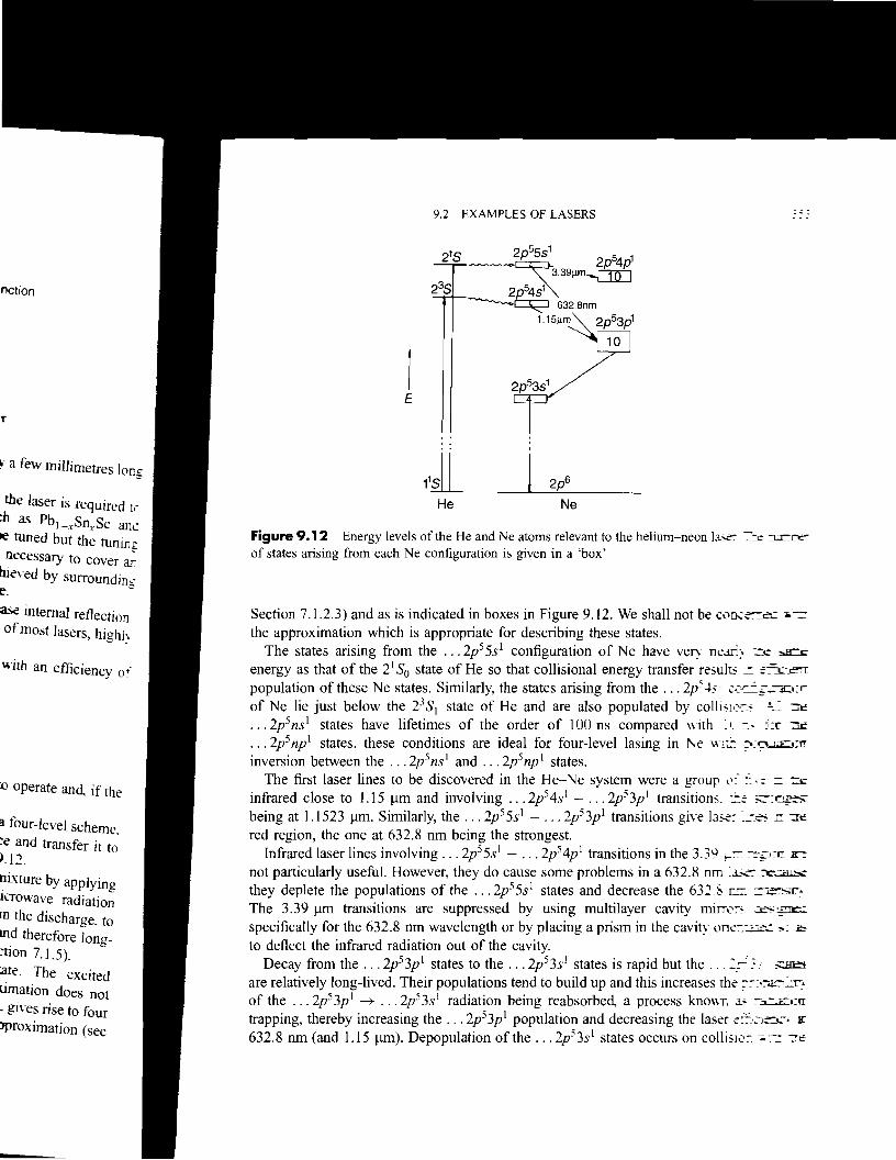
Figure 9.12 Energy levels of the He and Ne atoms relevant to the helium-neon la-x:- ~c ::J.r:o:of states arising from each Ne configuration is given in a 'box'
Section 7.1.2.3) and as is indicated in boxes in Figure 9.12. We shall not be C0n..::~~.: --c: the approximation which is appropriate for describing these states.
The states arising from the ... 2p5SS I configuration of Ne have very neaf,:' :::~ ~
energy as that of the 21So state of He so that collisional energy transfer results ==:=i..-~ population of these Ne states. Similarly, the states arising from the ... 2p~ -+5 ..::e':=-.,;.nr:l:r: of Ne lie just below the 23SI state of He and are also populated by colhslc,c;s ~::tc .. . 2p 5ns l states have lifetimes of the order of 100 ns compared with 11:':---, J:r ::II:
.. . 2p 5np l states. these conditions are ideal for four-level lasing in ~e \\1t!: =-:C'l...:%:crr
inversion between the .. . 2p 5ns l and .. . 2p 5np l states. The first laser lines to be discovered in the He-Ne system were a group 0:" ::"'.:: =::tc
infrared close to US J..lm and involving ... 2p54s 1 - •.• 2p53p l transitions. =-:: ~-:.-:r'~
being at 1.1523 J..lm. Similarly, the ... 2p55s1 - ... 2p53p l transitions giw las.e= :=-J~ r: m: red region, the one at 632.8 nm being the strongest.
Infrared laser lines involving ... 2p55s1 - ••. 2p54p l transitions in the 3.39 ~= :-::-;:o~ x-= not particularly useful. However, they do cause some problems in a 632.8 urn la.X'C ~
they deplete the populations of the .. . 2p55s1 states and decrease the 632.50 ru= :=i~r:.
The 3.39 J..lm transitions are suppressed by using multilayer cavity miITo:-s ~
specifically for the 632.8 nm wavelength or by placing a prism in the cavity one::::.;.:.::-.: ;..: .b
to deflect the infrared radiation out of the cavity. Decay from the .. . 2p53p l states to the .. . 2p53s J states is rapid but the ... 2~: ~
are relatively long-lived. Their populations tend to build up and this increases the :,:-:.:-.a.-,~r..
of the .. . 2p53p l --+ .. . 2p53s1 radiation being reabsorbed, a process knO\m as :-~I:n
trapping, thereby increasing the .. . 2p53p l population and decreasing the laser e:::}~)~,--. Bl"
632.8 nm (and US J..lm). Depopulation of the ... 2p53s 1 states occurs on colli 510:-.....-= :Ct:

.
9.2.6 The argon ion and krypton ion lasers
Figure 9.13 A helium-neon laser
2 The :e, the u,J.l
-
The mok(1.J configurJ ::c' rise to the. singlet anj particular. t
equilibnur. In a hl~r
two eb::rru because 1\
whereas t'r the ntar u
The specrrc'~'
lasers becau~e
lasers were rlr~
The grounc
The excited ~L
orbital into e'-I arise from rr01 gives rise Ic' ~ one of the : p
The Ar- '1J;
being at -lS:-' ,t. 800 nm re~l0
contains a :r.~
range of \\ .1\
9.2.7 The lIirr
(9.141tan4>=n
r------,"!!:!oX III") -tt99·5%
( 9 LASERS AND LASER SPECTROSCOPY
walls of the discharge tube. For this reason narrow tubes, only a few millimetres in diameIe::. are used.
Figure 9.13 illustrates the construction of a helium-neon laser. In this example ttc discharge in the gas mixture (typically ten parts of He to one of Ne at a total pressure c: about I Torr) is excited by internal electrodes. On the ends of the discharge tube are Brewster angle windows to prevent excessive light loss from multiple transmissions. If ;, window is at 90° to the optic axis of the laser a certain percentage is lost every time the radiation passes through. However, if the window is oriented at Brewster's angle 4>. a.5
shown, some is lost by reflection on the first transmission but no more is lost on subsequen: transmissions. As the figure also shows, for unpolarized radiation incident from inside the cavity, the transmitted and reflected radiation are plane polarized, the planes being at 90' to
each other. The laser beam is, therefore, plane polarized. One of the mirrors forming the laser cavity is as close to 100% reflecting as possible
(99.5%); the other is coated to allow I% of the radiation to emerge as the laser beam. Brewster's angle is given by
where n is the refractive index of the window material. Since n varies with wavelength, so does 4> but, for glass in the visible region, 4> ::::::: 57° and varies little with wavelength.
Laser action occurs in the noble gas ions Ne+, Ar+ Kr+ and Xe+ but that in Ar+ and Kr+ produces the most useful lasers.
These ion lasers are very inefficient, partly because energy is required first to ionize the atom and then to produce the population inversion. This inefficiency leads to a serious problem of heat dissipation, which is partly solved by using a plasma tube, in which a lowvoltage high-current discharge is created in the Ar or Kr gas, made from beryllium oxide, BeO, which is an efficient heat conductor. Water cooling of the tube is also necessary.
Most Ar+ and Kr+ lasers are CW A gas pressure of about 0.5 Torr is used in a plasma tube of 2-3 rom bore. Powers of up to 40 W distributed among various laser wavelengths can be obtained.
354

nillimetres in diam
~. In this example nr e at a total pressure Cl
he discharge tube a...~
pie transmissions. If II , is lost every time !he 3rewster's angle ({J. ~
'e is lost on subseque':l!: lCident from inside ~
planes being at 90 L:'
reflecting as possible as the laser beam.
(9.1~
~ with wavelength. x ~ith wavelength.
9.2 EXAMPLES OF LASERS 355
The spectroscopy of ion lasers is generally less well understood than that of neutral atom lasers because of the lack of detailed knowledge of ion energy-level schemes. Indeed, ion lasers were first produced accidentally and attempts to assign the transitions came later.
The ground configuration of Ar+ is KL3s23p 5, giving an inverted 2P3/Z, 2 P I/2 multiplet. The excited states involved in laser action involve promotion of an electron from the 3p orbital into excited 4s,5s,4p,5p,3d,4d, ... orbitals. Similarly, excited states of Kr+ involved arise from promotion of an electron from the 4p orbital. In Ar+ the KL3s23p4 configuration gives rise to IS, 3P, I D terms (see Section 7.1.2.3). Most laser transitions involve the core in one of the 3P states and the promoted electron in the 4p orbital.
The Ar+ laser produces about ten lines in the 454 nm to 529 nm region, the most intense being at 488.0 nm and 514.5 nm. The Kr+ laser produces about nine lines in the 476 nm to 800 nm region, with the 647.1 nm line being the most intense. Quite commonly, a laser contains a mixture of argon and krypton gases and is capable of producing a fairly wide range of wavelengths.
The nitrogen (N2) laser
The molecular orbital configuration ofN2 has been described in Section 7.2.1.1. The ground configuration of Equation (7.57) can be abbreviated to ... «(Ju*2S)2(1tu2p)\(Jg2Pi and gives rise to the X I1:i ground state. When an electron is promoted to a higher-energy orbital, singlet and triplet states result. We shall be concerned here with only the triplet states and, in particular, the A3 I~, B3IIg and C3II states.2 The orbital configurations and values ofre , theu
equilibrium internuclear distance, for these states are given in Table 9.1. In a high-voltage discharge through nitrogen gas there is a deep pink glow due mainly to
two electronic band systems in emission. The B-A system, or so-called first positive system because it was thought initially to be due to Nt, stretches from the red to the green region whereas the C-B system, or so-called second positive system, stretches from the blue into the near ultraviolet.
Table 9.1 Molecular orbital (MO) configurations and equilibrium bond lengths re of N2
t that in Ar+ and Kr- State MO configuration re/A
X1I+ ... «(Ju*2S)2(1tu2p)\(Jg2p)2 1.0977ired first to ionize the g
cy leads to a serious A3It ... «(J::2d(nu2p)\(Jg2p)2(npp)1 1.2866
rube, in which a low B3IIg ... «(J::2shnu2p)\(Jg2p)l(ni2p)1 1.2126
from beryllium oxide. C3IIu '" «(J::2s) I (nu2pt«(Jg2p)2(npp) I 1.1487 is also necessary.
:T is used in a plasma JUS laser wavelengths 2 The reader is reminded that the labels A, B, C rather than a, b, c for triplet states of N2 do not follow
the usual convention.
356 9 LASERS AND LASER SPECTROSCOPY
two-level lJ,,;' state mob':L:' two atom~. c'lMirrorLaser fairly high. "
output An Xe: c importanc'" J
and bounJ ,; consisting. 11
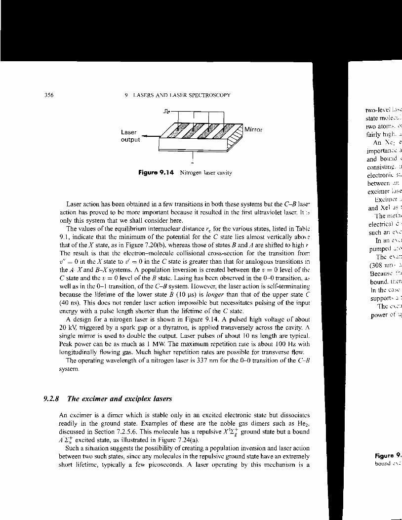
Figure 9.14 Nitrogen laser cavity electronIC ~t~
between In excimer Ll,e
Exci!11er :;Laser action has been obtained in a few transitions in both these systems but the C-B 1a..'CC and Xel J' t
action has proved to be more important because it resulted in the first ultraviolet laser. It l~ The !11et:h only this system that we shall consider here. electrical 2:~
The values of the equilibrium internuclear distance r for the various states, listed in Tablee such an c"-:'"9.1, indicate that the minimum of the potential for the C state lies almost vertically aboyc In an C',1that of the X state, as in Figure 7.20(b), whereas those of states B and A are shifted to high r pumped J~c' The result is that the electron-molecule collisional cross-section for the transition froIT. The ",,,,,:1v" = 0 in the X state to Vi = 0 in the C state is greater than that for analogous transitions in
(308 nm' .:.the A-X and B-X systems. A population inversion is created between the v = 0 level of the Because tCo.t C state and the v = 0 level of the B state. Lasing has been observed in the 0-0 transition, ~ bound. thcr, well as in the 0-1 transition, of the C-B system. However, the laser action is self-terminating
In the CJ~e because the lifetime of the lower state B (10 ~s) is longer than that of the upper state C supports J ! (40 ns). This does not render laser action impossible but necessitates pulsing of the input The ",,,e:1energy with a pulse length shorter than the lifetime of the C state. power llf U]
A design for a nitrogen laser is shown in Figure 9.14. A pulsed high voltage of about 20 kY, triggered by a spark gap or a thyratron, is applied transversely across the cavity. A single mirror is used to double the output. Laser pulses of about IOns length are typical. Peak power can be as much as I MW The maximum repetition rate is about 100 Hz with longitudinally flowing gas. Much higher repetition rates are possible for transverse flow.
The operating wavelength of a nitrogen laser is 337 nm for the 0-0 transition of the C-B system.
9.2.8 The excimer and exciplex lasers
An excimer is a dimer which is stable only in an excited electronic state but dissociates readily in the ground state. Examples of these are the noble gas dimers such as He2, discussed in Section 7.2.5.6. This molecule has a repulsive XI.ri ground state but a bound A l.rt excited state, as illustrated in Figure 7.24(a).
Such a situation suggests the possibility of creating a population inversion and laser action between two such states, since any molecules in the repulsive ground state have an extremely Figure 9. short lifetime, typically a few picoseconds. A laser operating by this mechanism is a bound -:\~
>r
iI1eS. listed in Ta....~
1St vertically ab..,~
re shifted to higl: r_
be transition 1TCft ~(lUS transitions _ 1= 0 le\-el of~
~ O-D transition. a is self-tenninatln! the upper state C
alsing of the inru
I \"oltage of ab.."'Ul ross the ca\it\ A
length are typIcal bout I00 Hz \\Tth transverse ftO\\_
15lrion of the C-B
te but dissociat~
m such as He:_ state but a boun.:!
n and laser actIolC IaYe an extreme~
mechanism is ,1
9.2 EXAMPLES OF LASERS 357
two-level laser but population of the upper state is not, of course, caused by pumping ground state molecules. Molecules in the upper state are created in a discharge by collisions between two atoms, one or both of which may be in an excited state. The efficiency of such lasers is fairly high, about 20 per cent.
An Xe2 excimer laser has been made to operate in this way, but of much greater importance are the noble gas halide lasers. These halides also have repulsive ground states and bound excited states: they are examples of exciplexes. An exciplex is a complex consisting, in a diatomic molecule, of two different atoms, which is stable in an excited electronic state but dissociates readily in the ground state. In spite of this clear distinction between an excimer and an exciplex it is now common for all such lasers to be called excimer lasers.
Excimer lasers employing NeF, ArF, KrF, XeF, ArCI, KrCI, XeCI, ArBr, KrBr, XeBr, KrI, and XeI as the active medium have been made.
The method of excitation was, in the early days, by an electron beam but now a transverse electrical discharge, like that for the nitrogen laser shown in Figure 9.14, is used. Indeed such an excimer laser can be converted to a nitrogen laser by changing the gas.
In an excimer laser the mixture of inert gas, halogen gas, and helium, used as a buffer, is pumped around a closed system consisting of a reservoir and the cavity.
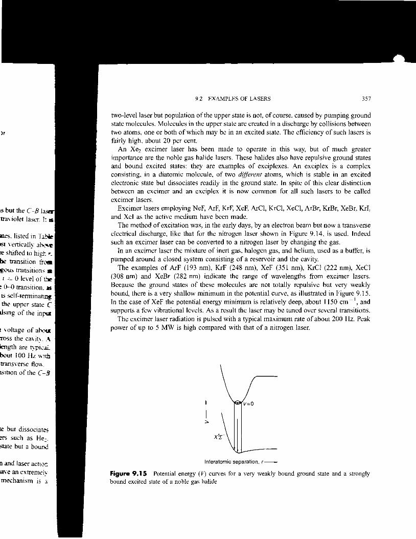
The examples of ArF (193 nm), KrF (248 nm), XeF (351 nm), KrCI (222 nm), XeCI (308 nm) and XeBr (282 nm) indicate the range of wavelengths from excimer lasers. Because the ground states of these molecules are not totally repulsive but very weakly bound, there is a very shallow minimum in the potential curve, as illustrated in Figure 9.15. In the case of XeF the potential energy minimum is relatively deep, about 1150 cm - I, and supports a few vibrational levels. As a result the laser may be tuned over several transitions.
The excimer laser radiation is pulsed with a typical maximum rate of about 200 Hz. Peak power of up to 5 MW is high compared with that of a nitrogen laser.
:::..
Interatomic separation. r-
Figure 9.15 Potential energy (V) curves for a very weakly bound ground state and a strongly bound excited state of a noble gas halide

358 9 LASERS AND LASER SPECTROSCOPY
9.2.9 The carbon dioxide laser
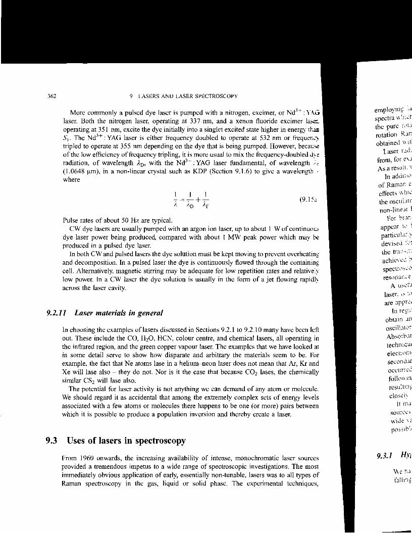
The CO2 laser is a near-infrared gas laser capable ofvery high power and with an efficien.:-:, of about 20 per cent. CO2 has three normal modes ofvibration: VI' the symmetric stretch. \:the bending vibration, and "3, the antisymmetric stretch, with symmetry species at, nu ' an': at, and fundamental vibration wavenumbers of 1354, 673, and 2396 cm - 1, respectiwl:Figure 9.16 shows some of the vibrational levels, the numbering of which is explained 1:".
footnote 4 of Chapter 4 (page 93), which are involved in the laser action. This occur;; principally in the 3b2~ transition, at about 10.6 ~m, but may also be induced in the 3(11 transition, at about 9.6 ~m.
Population of the 31 level is partly by electron-molecule collisions and partly by energ: transfer from nitrogen molecules in the v = 1 level, this being metastable due to the fact tha: the transition to v = 0 is forbidden (see Section 6.1.1). Energy transfer from nitrogen i;; particularly efficient because the v = I level is only 18 cm - 1 below the 31 level of CO: (Figure 9.16). Because of near-degeneracies of higher vibrational levels of nitrogen and the " 3 stack of COlo transfer to levels such as 32
, 33, '" also occurs. Transitions down the y:
stack are fast until the 31 level is reached. Decay of the 11 and 22 lower levels3 of the laser transitions are rapid down to the 21 leveL
this is depopulated mostly by collisions with helium atoms in the CO2 : N 2 : He gas mixhlre which is used.
Lifetimes of upper and lower states are governed by collisions and that of the upper is always longer than that of the lower in the gas mixmres used.
The energy input into a CO2 laser is in the form of an electrical discharge through the mixmre of gases. The cavity may be sealed, in which case a little water vapour must be added in order to convert back to CO2 any CO which is formed. More commonly. longihldinal or, preferably, transverse gas flow through the cavity is used. The CO2 laser can operate in a CW or pulsed mode, with power up to I kW possible in the CW mode.
31 ~ V ~. -1
.// 18cm-1
~ 2000 1 E JO'6~m9'6 ~ 1:. ...." 2' \.4 "mQ)
..c
~ 1000 L21
~ 0' zero-point -0
C02 N2
Figure 9.16 Vibrational levels of N2 and CO2 relevant to the CO2 laser
3 The assignments of these levels was reversed in 1965. The new assignments are used here.
Each oftt~c
for linear mc': and R bran.:n; Figure 6.:::~
Unless the the highe;;t ~
highest POf U1
temperature;; of rotationJ I
The ca\ It: one of the m
9.2.10 The dy
Laser a,t:c':l This led :,'
range. D::- c One ,~.r
electrom.: ;;1
ofa dye ;-; Equation ::: Equation
Figure" . the typi,)ll
Figure (5 I' \ "
and ItlJ! ,
Charle : ~
Dekker. '
The dye laser
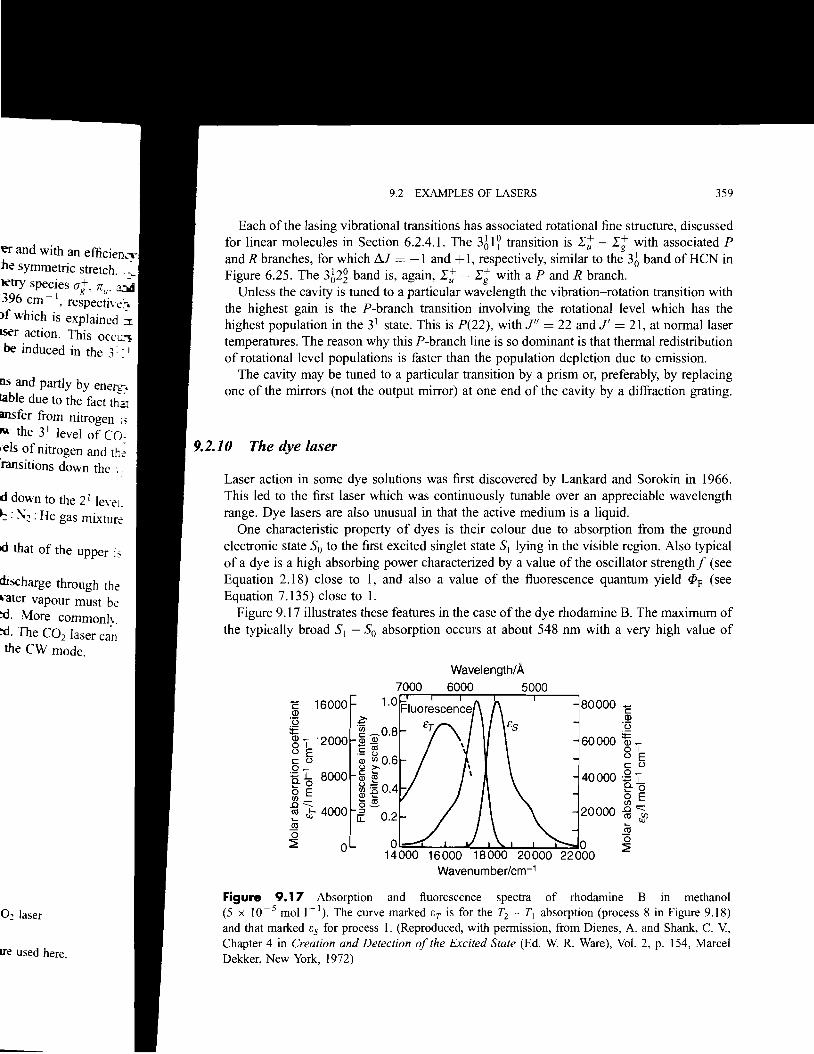
Figure 9.17 Absorption and fluorescence spectra of rhodamine B in methanol (5 x /0-5 moll-I), The curve marked tT is for the Tz T] absorption (process 8 in Figure 9.18) and that marked ts for process I. (Reproduced, with permission, from Dienes, A. and Shank, C. V, Chapter 4 in Creation and Detection of the Excited State (Ed. W. R. Ware), Vol. 2, p. 154, Marcel Dekker, New York, 1972)
359
80000 C Q)
'(3
60000 i~L 01 (J E C (J
40000 2'10.~ 0 o E
20000 Jg,~JP l'll o ~ K ! >, I , ' .............. 0
'~' ! - H - • • 22000
9.2 EXAMPLES OF LASERS
z. '~ ~0.8 Ql Ql
E«i, ()
~ ~O,6 c: ~
Ql £': ~:'::04CD -e . ~ al o~ :::J IT:
o
~ 16000 '(3
i: ~ 'I 12000 (J E C (J
~~ 8000 Sl E.0, ~ JJ 4000
.!l1 o ~
Each of the lasing vibrational transitions has associated rotational fine structure, discussed for linear molecules in Section 6.2.4.1. The 361? transition is .r~ - .ri with associated P and R branches, for which j'.J = -I and + 1, respectively, similar to the 36 band of HeN in Figure 6.25. The 362g band is, again, .r~ - .ri with a P and R branch.
Unless the cavity is tuned to a particular wavelength the vibration-rotation transition with the highest gain is the P-branch transition involving the rotational level which has the highest population in the 31 state. This is P(22), with F = 22 and J' = 21, at normal laser temperatures. The reason why this P-branch line is so dominant is that thermal redistribution of rotational level populations is faster than the population depletion due to emission.
The cavity may be tuned to a particular transition by a prism or, preferably, by replacing one of the mirrors (not the output mirror) at one end of the cavity by a diffraction grating.
Laser action in some dye solutions was first discovered by Lankard and Sorokin in 1966. This led to the first laser which was continuously tunable over an appreciable wavelength range. Dye lasers are also unusual in that the active medium is a liquid.
One characteristic property of dyes is their colour due to absorption from the ground electronic state So to the first excited singlet state SI lying in the visible region. Also typical of a dye is a high absorbing power characterized by a value of the oscillator strengthf (see Equation 2.18) close to 1, and also a value of the fluorescence quantum yield ([)F (see Equation 7.135) close to I.
Figure 9.17 illustrates these features in the case of the dye rhodamine B. The maximum of the typically broad SI - So absorption occurs at about 548 nm with a very high value of
os and partly by enerc;:. table due to the fact thaI msfer from nitrogen ~~ M the 3 I level of CO: ,'els of nitrogen and the 'ransitions down the ',.
0: laser
Ire used here.
discharge through the '<iter vapour must be :d. More commonly. =d. The CO2 laser can the CW mode.
~ and with an efficieD..::" :he symmetric stretch.. :
. +,_...Jetry speCIes a g , Jr u
• a:Ju
396 cm - I, respectiwt. )f which is explained :II
LSer action. This OCCI..n
be induced in the 3 : II
id that of the upper is
d down to the 21 lewl. ~: ~2: He gas mixture
:
9 LASERS AND LASER SPECTROSCOPY
Since ~. ( The hfe:~l
9.18. is -;:'~:
amount l': j
result is tr~.i
many d:e 1
9.18. l'\ e~i
decreasin;: proces:, I- 1
In orJe~
rate 10\\ e:sufficien:i:, overlap \,1
There .lJ
which. lc'~
930 nm ~I
moll :,
Takl1l:= pro\ide :1
intensW' dye Ll-e:-:
A ~'l.:~
the d:e ~,
and \\ I:r. 10\\ . u:'
direction 0: C
absorption 1~ :'
level of S . : fluorescen.:: e : whereas the ~;
following prc>' S1 and \ibrJ:~
levels are (':. The pOpl.. .'
molecule frc'~
non-radial]\ e discussed I:".
9.18, W\l1'::[-. ~
order 0 f \1 II I
T2
T1 ---.. !
51 ,!, K i
5
52 f ~ ..
50 I •
El
80000 I mol- 1 cm -1 for Cmax , the maximum value of the molar absorption coeffic;;;-:l[ (Equation 2.16). The fluorescence curve shows, as usual, an approximate mirror iill? relationship to the absorption curve. It has the additional property, important for all Ia...~
dyes, that the fluorescence and absorption maxima do not coincide: if they did, a lar~
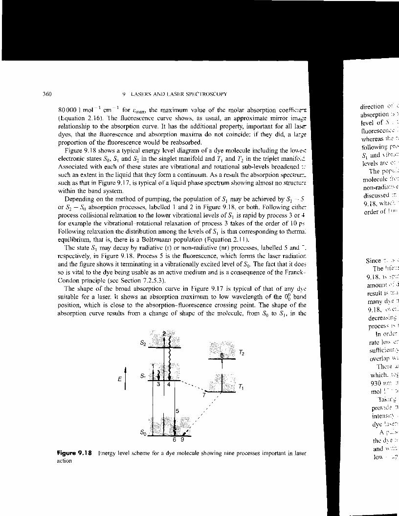
proportion of the fluorescence would be reabsorbed. Figure 9.18 shows a typical energy level diagram of a dye molecule including the 10wK
electronic states So, SI and S2 in the singlet manifold and TI and T2 in the triplet manifo;c Associated with each of these states are vibrational and rotational sub-levels broadened :~
such an extent in the liquid that they form a continuum. As a result the absorption spectruL such as that in Figure 9.17, is typical of a liquid phase spectrum showing almost no strucru:-e within the band system.
Depending on the method of pumping, the population of SI may be achieved by SI - 5 or S2 - So absorption processes, labelled 1 and 2 in Figure 9.18, or both. Following eithc: process collisional relaxation to the lower vibrational levels of SI is rapid by process 3 or ~
for example the vibrational-rotational relaxation of process 3 takes of the order of lOps Following relaxation the distribution among the levels of SI is that corresponding to therma: equilibrium, that is, there is a Boltzmann population (Equation 2.11).
The state SI may decay by radiative (r) or non-radiative (nr) processes, labelled 5 and -. respectively, in Figure 9.18. Process 5 is the fluorescence, which forms the laser radiatior, and the figure shows it terminating in a vibrationally excited level of So' The fact that it does so is vital to the dye being usable as an active medium and is a consequence of the FranckCondon principle (see Section 7.2.5.3).
The shape of the broad absorption curve in Figure 9.17 is typical of that of any dye suitable for a laser. It shows an absorption maximum to low wavelength of the og band position, which is close to the absorption-fluorescence crossing point. The shape of the absorption curve results from a change of shape of the molecule, from So to SI' in the
Figure 9.18 Energy level scheme for a dye molecule showing nine processes important in laser action
360

Iar absorption coeffio 'Proximate mirror i =
y. important for all J.'ide: if they did, a j
1lle including the 10\, : in the triplet manifcojd sub-levels broadened .. be absorption spectru::m.. .ing almost no stru('l1-~
~ achieved by 51 -.s. both. Following either
apid by process 3 or 4: of the order of I0 ~ 'reSponding to thermal
;ses. labelled 5 and -. ns the laser radiatIC":': ,- The fact that it doe~ lJeT!ce of the Franck-
I of that of any dye ngth of the og bane 1. The shape of the >m So to 5J , in the
unportant in laser
9.2 EXAMPLES OF LASERS 361
direction of one or more normal coordinates, so that the most probable transItIOn in absorption is to a vibrationally excited level of51- Similarly, in emission from the zero-point level of 51' the most probable transition is to a vibrationally excited level of 50' The fluorescence lifetime 'r for spontaneous emission from 5] is typically of the order of I ns whereas the relaxation process 6, like process 3, takes only about lOps. The result is that, following processes 1 and 3, there is a population inversion between the zero-point level of 51 and vibrationally excited levels of 50 to which emission may occur, provided that these levels are of sufficiently high energy to have negligible thermal population.
The population of 5] may also be reduced by absorption of the fluorescence taking the molecule from 5] into 52' if the wavelengths of the two processes correspond, as well as by non-radiative transitions to either So (internal conversion) or T1 (intersystem crossing), as discussed in Section 7.3.6. In dye molecules it is the 5] - T I process, labelled 7 in Figure 9.18, which is the most important. This is a spin-forbidden process with a lifetime 'nr of the order of 100 ns. The lifetime, of the state 51 is related to 'nr and the radiative lifetime 'r by
1 I 1 -=-+- (9.15) , 'r 'm
Since 'r is of the order of 1 ns, fluorescence is the dominant decay process for 51' The lifetime 'T of the state T l is long because the T1 - 50 transition, process 9 in Figure
9.18, is spin-forbidden. Depending on the molecule and on the conditions, particularly the amount of dissolved oxygen, it may be anywhere in the range 100 ns to 1 ms. If,T > 'm the result is that the concentration of molecules in T] can build up to a high level. It happens in many dye molecules that the intense, spin-allowed, T2 - T] absorption, process 8 in Figure 9.18, overlaps with, and therefore can be excited by, the 5] - 50 emission, thereby decreasing the efficiency of the laser considerably. Figure 9.17 shows how important this process is in rhodamine B.
In order to prevent this occurring a pulsed method of pumping is used with a repetition rate low enough to allow time for T] - 50 relaxation. For CW operation either, T must be sufficiently short or another dye has to be used for which T2 - T l absorption does not overlap with the fluorescence.
There are many dyes available, each of which can be used over a 20-30 nm range and which, together, cover a wavelength range from about 365 nm in the ultraviolet to about 930 nm in the near-infrared. Dye concentrations are low, typically in the range 10- 2
mol I-I to 10-4 moll-I. Taking into account the possibility of frequency doubling (Section 9.1.6) dye lasers can
provide tunable radiation throughout the range 220-930 nm but with varying levels of intensity and degrees of difficulty. The tunability and the extensive wavelength range make dye lasers probably the most generally useful of all visible or ultraviolet lasers.
A pulsed dye laser may be pumped with a flashlamp surrounding the cell through which the dye is flowing. With this method of excitation pulses from the dye laser about 1 IlS long and with an energy of the order of 100 mJ can be obtained. Repetition rates are typically low - up to about 30 Hz.
362 9 LASERS AND LASER SPECTROSCOPY
employin~ ,.1More commonly a pulsed dye laser is pumped with a nitrogen, excimer, or Nd3+: Y.\G spectra \\hl.:il
laser. Both the nitrogen laser, operating at 337 nm, and a xenon fluoride excimer la..~ the pure roD operating at 351 nm, excite the dye initially into a singlet excited state higher in energy th.3ID rotation R3.rfSt. The Nd3+ : YAG laser is either frequency doubled to operate at 532 nm or frequen.:-::. obtained \\ It]
tripled to operate at 355 nm depending on the dye that is being pumped. However, beca~~ Laser r3.(h
of the low efficiency of frequency tripling, it is more usual to mix the frequency-doubled d:- := from, for c,Jradiation, of wavelength AD, with the Nd3+: YAG laser fundamental, of wavelength ;= As a result. \1
(1.0648 11m), in a non-linear crystal such as KDP (Section 9.1.6) to give a wavelength In add1ll(Y
where of Raman c effects \\ hi':1 1 1
(9.1~2-=-+ the OSCl\\3.t1lA AD AF non-linc3.r I
For br.lf.,Pulse rates of about 50 Hz are typical. appear te' 1CW dye lasers are usually pumped with an argon ion laser, up to about I W of continuous particuL1r~~dye laser power being produced, compared with about 1 MW peak power which may be deviscd :·,'1produced in a pulsed dye laser. the tra11 ,<::In both CWand pulsed lasers the dye solution must be kept moving to prevent overheating achie\c~ jand decomposition. In a pulsed laser the dye is continuously flowed through the containing spectr(".: 0 cell. Alternatively, magnetic stirring may be adequate for low repetition rates and relatively resonan.: clow power. In a CW laser the dye solution is usually in the form of a jet flowing rapidly
A U,.c;uacross the laser cavity. laser. b :e' are apprc c
In re~IL9.2.11 Laser materials in general obtain .In oscillat0rIn choosing the examples oflasers discussed in Sections 9.2.1 to 9.2.10 many have been left Absorb.lfout. These include the CO, H20, HCN, colour centre, and chemical lasers, all operating in techmqu,the infrared region, and the green copper vapour laser. The examples that we have looked at electfLll1l'in some detail serve to show how disparate and arbitrary the materials seem to be. For second.lfexample, the fact that Ne atoms lase in a helium-neon laser does not mean that Ar, Kr and occurrcdXe will lase also - they do not. Nor is it the case that because CO2 lases, the chemically follo\\ msimilar CS2 will lase also. resu\tln~The potential for laser activity is not anything we can demand of any atom or molecule. closd\We should regard it as accidental that among the extremely complex sets of energy levels
It n13.associated with a few atoms or molecules there happens to be one (or more) pairs between sour.:c.;.which it is possible to produce a population inversion and thereby create a laser. wide \, pos';'l!:'l,
9.3 Uses of lasers in spectroscopy
9.3.1 HYJFrom 1960 onwards, the increasing availability of intense, monochromatic laser sources provided a tremendous impetus to a wide range of spectroscopic investigations. The most
Wc h3.immediately obvious application of early, essentially non-tunable, lasers was to all types of
fa\\ll1:lRaman spectroscopy in the gas, liquid or solid phase. The experimental techniques,
-