laser surface coating of bulk metallic glass composition on high carbon low alloy steel 63 rd atm,...
TRANSCRIPT

Laser surface coating of bulk metallic glass Laser surface coating of bulk metallic glass composition on high carbon low alloy steelcomposition on high carbon low alloy steel
63rd ATM, 16th November, 2009
A. Basu1*, J. Dutta Majumdar2, N.B. Dahotre3, I. Manna2
1Metallurgical & Materials Engineering Department, N.I.T., Rourkela Orissa. 7690082Metallurgical & Materials Engineering Department, I.I.T., Kharagpur, W.B. 721302
3Department of Materials Science and Engineering, University of Tennessee, Knoxville, TN 37996, USA

Bulk Amorphous AlloyMet-glass is a supercooled liquid with no long-range periodicity and possessing near-theoretical strength, large elastic deformation, high hardness, excellent wear resistance [Klement, Willens, Duwez, Nature, 1960]
Properties of BAAs � Multi-component alloys�dT/dt)Cr 103 K/s�Deep eutectic�HM (enthalpy of mixing)� (viscosity) > 109 Pa-s at Tg
� (str. relax. time) near TMP
Evolution of Met-glass/BAAs Klement et al., Nature (1960)Inoue et al., J. Mater. Sci. Lett. (1987)Masumoto et al. Jpn.J. Appl.Phy. (1988)Inoue et al., Mater. Trans JIM (1991)Peker, Johnson, Appl. Phy. Lett. (1993)
Crystal
Liquid
MG BAAst, s
T, KMechanical Properties � High Hardness, Strgth� High Young Modulus

SystemsSl. Year Substrate/deposit Laser Reference
1 1980 Chilled cast iron Nd: Glass,pulsed Snezhnoi et al.
2 1980 Cast tool steel /Fe-B (sprayed) CW-CO2 Bergmann-Mordike
3 1981 Fe-2C-12Cr/Fe-B Nb-alloy CW-CO2 Bergmann-Mordike
4 1981 Fe-C/Si-P-B (ternary/quaternary) TEA-CO2 pulsed Borodona et al.
5 1982 Fe-Fe3B, (modulated thin film) Nd:YAG, pulsed Lin-Spaepen
6 1983 Fe-4 at.% B Nd:YAG, pulsed Lin-Spaepen
7 1984 Mo/Ni (30-60 at%), Mo/Co (45 at%), Co/Nb (40 at%)
Nd:YAG, mode locked
Lin et al.
8 1984 Ni-Nb thin film Zr/Cu Nd:YAG Lin-Spaepen
9 1984 Zr/Cu Nd:YAG, Q-switched Den Broeder et al.
10 1984 Au- Ti, Co- Ti, Cr- Ti, Zr- Ti Pulsed Affolter-von Allmen
11 1984 Pd-6Cu-16Si CW-CO2 Yoshioka et al.
12 1984 Fe-10Si-15B Pulsed CO2 Kumagai et al.
13 1985 Fe-10Cr-5Mo/12-14 P, C CW-CO2 Yoshioka et al.
14 1985 Pure Ga KrF excimer Frohlingsdorf et al.
15 1987 Mild steel/Ni-Cr-16P-4B CW-CO2 Yoshioka et al.
16 1987 Ni, Cu(Ni), Ti(Ni)/Pd-25Rh-10P-9Si CW-CO2 Kumagai et al.

Sl. Year Substrate/deposit Laser Reference
17 1988 Nb/Ni-Pt-Pd-Rh CW-CO2 Kumagai et al.
18 1988 Fe-Cr-P-C-Si CW-CO2 Gaffet et al.
19 1990 Review-paper Hashimoto et al.
20 1991 SiC Knotek and Loffler
21 1995 Cu/PdCuSi CW-CO2 and Nd:YAG Wang et al.
22 1997 AI-Si/Ni-WC Plasma sprayed and laser melted with a CW-CO2 laser Liang and Wong
23 1997 AI-Si/Ni-Cr-B-Si Plasma sprayed and laser melted with a CW-O2 laser Liang and Wong
24 1997 AI-Si/Ni-Cr-AI Plasma sprayed and laser melted with a CW-CO2 laser Liang and Wong
25 1997 Al/Zr60Al15Ni25 Carvalhoa et al.
26 1999 Al alloy/Ni-Cr-Al CW-CO2 Li et al.
27 1999 Ni-Cr-B-Si-C CW-CO2 Li et al.
28 1999 Concrete CW-CO2 Lawrence and Li
29 2000 (Austenitic SS) SiO2 Nd:YAG Wu and Hong
30 2000 Al alloy/Ni-Cr-B-Si and Ni-Cr-Bi-WC
CO2 Wong et al.
31 2000 Al alloy/Ni-Cr-Al CW-CO2 Liang and Su
32 2000 (Austenitic SS) Zr Pulsed Nd:YAG Wu and Hong
33 2000 Cu/Al2O3 Shepeleva et al.
34 2000 Al-Si/Ni-Cr-Al CW-CO2 Liang et al.
35 2000 (Fe) Fe57Co8Ni8Zr8 CW-CO2 Wu and Hong
36 2001 Fe57Co8Ni8Zr10Si4B13 Xiaolei and Youshi

SUBSTRATE : SAE 52100
Equivalent grades AISI 52100 (USA), EN 31 (UK), SUJ 2 (Japan), DIN 100Cr6 (Germany) BS:2S135/535A99 (British), AFNOR:100C6 (France) IS 104Cr6 (India)
ElementElement CC SiSi MnMn CrCr FeFe
Wt %Wt % 0.95 – 1.050.95 – 1.05 0.15 – 0.350.15 – 0.35 0.29 – 0.400.29 – 0.40 1.50 – 1.651.50 – 1.65 RestRest
Spheroidized annealed
PROCESS : LASER COATINGDue to possible high cooling rate (~ 106 K/s)

EXPERIMENTAL
Laser: 2.5 kW Nd:Yag Beam size: 3 mm X 600 μm
Power density: 1.39 kW/mm2 Overlap: ~ 15%
Condition: Defocused by 0.5 mm Clad material: Fe48Cr15Mo14Y2C15B6k
Power: 1.5 and 2.0 kW Scan speed: 2.5 and 3.5 m/min
Scan type: Single and double (perpendicular to the first)
Laser Parameters:

XRD of Fe48Cr15Mo14Y2C15B6 powder shows a characteristic diffuse halo
DSC scan of Fe48Cr15Mo14Y2C15B6 at 200C/min. Arrow marks the Tg
XRD and DSC of PRE-COATED POWDER

PHASE EVOLUTION STUDY by XRD
Laser power: 1.5 kW powerScan speed: 350 cm/minType: double scan
Amount of Fe7C decreases with increase in applied power, scan
speed or multiple scan

SEM and OPTICAL MICROGRAPH (CROSS SECTION)Scan speed: 250 cm/min, scan type: single
Laser power: 1.5 kW
Laser power: 2.0 kW
• Two distinguished zone
• Significant grain coarsening when lased at a higher power.

SURFACE MECHANICAL PROPERTY: MICROHARDNESS
• 4 times improvement of base hardness
• Gradual decrease in hardness profile
• With increase in scan speed, surface hardness increases and depth of hardened surface zone decreases.
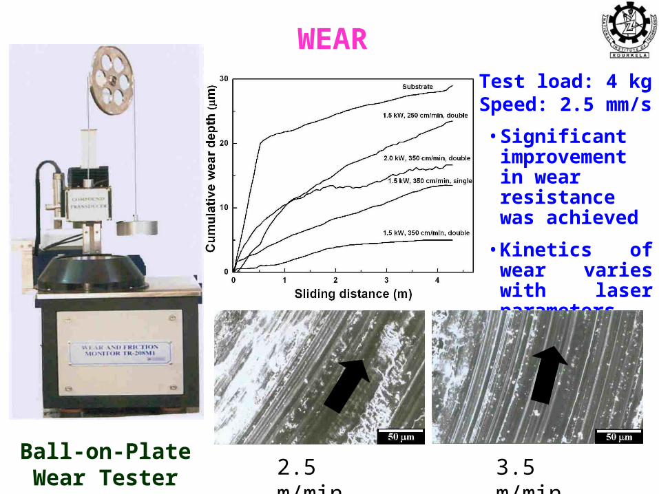
WEAR
Ball-on-Plate Wear Tester
Test load: 4 kg Speed: 2.5 mm/s
• Significant improvement in wear resistance was achieved
• Kinetics of wear varies with laser parameters.
2.5 m/min 3.5 m/min

DEPTH WISE SEM Laser power: 2.0 kW, Scan speed: 350 cm/min, scan type: double
Surface
Below surface
Magnified
Magnified
Away from the surface, the precipitates at the grain boundaries/interdendritic regions is less.

DEPTH WISE XRD and WEAR
• Carbide content is most on the surface and decrease slowly towards substrate as solidification starts near to the substrate.
• Wear resistance is more at surface layer due to presence of more amounts of hard phases like carbides.

A = absorptivity, I = laser power intensity, ε = emissivity of thermal radiation, tp = irradiation timeT0 = ambient temperature σ = Stefan-Boltzman constant (5.67 × 10⁻⁸ W/m2K4)
Convective boundary condition at the bottom surface of the sample is given by:
THERMAL PROFILE MODELLING
4
04),0,,(
),0,,(),0,,(),0,,(TtyxTAI
ztyxT
ytyxT
xtyxT
K
pttfor 01
pttfor 0
0),,,(
),,,(),,,(),,,(TtLyxTh
ztLyxT
ytLyxT
xtLyxT
K
h = convective heat transfer coefficient, k = thermal conductivity, L = sample thickness
At the surface of the sample, the heat balance between the laser energy absorbed by the
sample and the radiation losses :
• Melting is of amorphous clad precursor only.• Latent heat of formation of borides, carbides etc, are negligible.
and
Thermal profile on top surface

Attempt to develop amorphous coating by LSC not yet successful A defect free clad layer/coating with 250 to 600 mm thickness Cellular/dendritic microstructure Microhardness improved to as high as 950 VHN as compared to 240 VHN of
the substrate Significant improvement in wear resistance. Compressive residual stress in the clad layer/coating Failure attributed to compositional changes and not due to lack of required
quenching
SUMMARY