laser sintered resorbable pcl splints for treating ... sintered resorbable pcl splints for treating...
TRANSCRIPT

Laser Sintered Resorbable PCL Splints for Treating
Tracheobronchalmalacia (TBM) Scott J. Hollister1,2,3, Colleen L. Flanagan1, David A
Zopf4, Robert J. Morrison4, Richard G. Ohye5, Glenn E. Green4
1Department of Biomedical Engineering 2Department of Mechanical Engineering 3Department of Surgery 4Department of Otolaryngology 5Department of Cardiac Surgery The University of Michigan

• Tracheobronchalmalacia
• Tracheal Splint Clinical Goals & Design • Laser Sintering PCL Splints
• Clinical Use and Outcomes • Quality Control: Current & Future
Outline

Tracheobronchalmalacia (TBM)
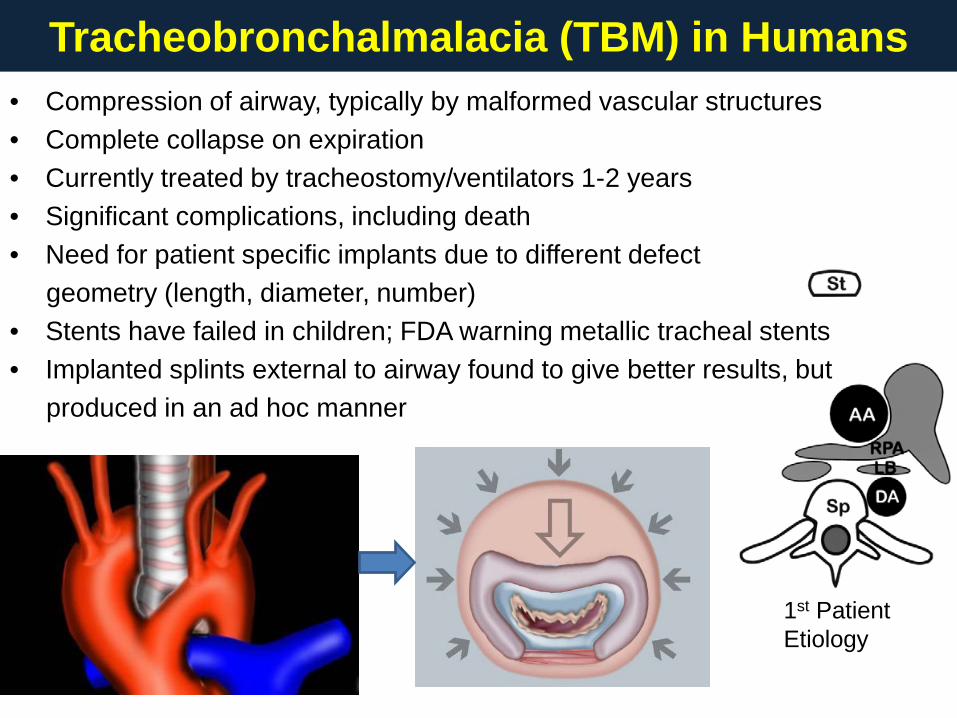
Tracheobronchalmalacia (TBM) in Humans
1st Patient Etiology
• Compression of airway, typically by malformed vascular structures • Complete collapse on expiration • Currently treated by tracheostomy/ventilators 1-2 years • Significant complications, including death • Need for patient specific implants due to different defect geometry (length, diameter, number) • Stents have failed in children; FDA warning metallic tracheal stents • Implanted splints external to airway found to give better results, but produced in an ad hoc manner

Tracheal Splint Clinical Goals and Design

• The splint should provide radial compressive mechanical support to keep the airway open and patent: M/B – 0.12 MPa artery; .01 MPa exhalation
• The splint should provide this radial mechanical support for a period of 24-30 months to allow tracheal remodeling and development: M/B
• The splint should allow transverse and bending displacement, not interfering with cervical motion: M
• The splint should allow growth and expansion of the tracheobronchial complex during this 24-30 month period: M - estimated 15N growth force
• The splint should not cause adverse tissue reaction or remodeling: B/M - Biocompatible
• The splint should not interfere with the mucociliary architecture with the trachealbronchial lumen; it therefore should be placed externally: B/S
• Second surgical procedure should be avoided to remove the splint; therefore, the splint should be bioresorbable: S/M – resorbable in 3 years Surgical placement of the splint and attachment of the tracheobronchus into the splint should be straightforward: S; suture holes in splint to “sling” airway
• Patient Specific to account for different malacic airway diameter/length: S/M
Clinical Design Goals: Implanted Splint External to Airway Mechanical Requirement: M; Biomaterial Requirement: B; Surgical Requirement:: S

• MATLAB program to automatically generate bellow design w suture holes • Design variables: inner diameter, open angle, spiral angle , bellow height, wall thickness, suture hole width, etc (> 3,000,000 design perturbations) • Input parameters from CT measurements from MIMICS Digital Model • Fit splint to patient model in MIMICS • Perform finite element analysis: compression, bending, opening (growth) • Complex patient specific design requires 3D printing
2nd Patient (1 of 2 splints)
3rd Patient (Only blue splint used)
Patient Specific Image-Based Design for Splint

Laser Sintering PCL Splints

Design and Manufacture Process: Outline CT Scan - 3DPatient Model inMimicsSplint Design &Analysis -MATLAB/MIMICS/FEA(Bellowallspiral050114)DesignManufactureReceiveRaw PCLMill PCLReceive HABlend PCL & 3-5% HALaser Sinter SplintsSet ParametersMimics:1. Generate Splint STL2. Size Splint toMalacicDefectSlice Splint STL FilesStore Raw PCLStore HATest Splint Geometry &MechanicsPackage & Label SplintSterilize Splint
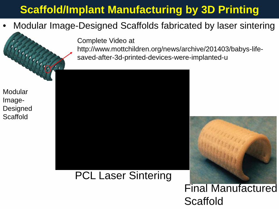
• Modular Image-Designed Scaffolds fabricated by laser sintering
Scaffold/Implant Manufacturing by 3D Printing
PCL Laser Sintering Final Manufactured Scaffold
Modular Image- Designed Scaffold
Complete Video at http://www.mottchildren.org/news/archive/201403/babys-life-saved-after-3d-printed-devices-were-implanted-u

• EOS P100 Laser Sintering System (www.eos.info/en)
• CAPA 6501 Polycaprolactone (PCL) purchased from Polysciences (www.polysciences.com) Target Mw = 50kDa
• Hydroxyapatite (HA) Plasma Biotal (www.plasma-biotal.com)
• Need to Cryogenically Mill Resorbable Polymers (PCL, PLA) Jet Pulverizer (www.jetpulverizer.com); Fraunhofer (http://www.umsicht.fraunhofer.de/en.html) ; Evonik (http://north-america.evonik.com); Target Particle Size Range: 25µm < x < 125 µm; Median 40-60 µm References: Partee et al., 2006, J Man Sci Eng, 128:531-540 Williams et al., 2005, Biomaterials, 26:4817-4827 Eshraghi, Das, 2010, Acta Biomaterialia; 6: 2467-2476 Eshraghi, Das, 2012, Acta Biomaterialia; 8: 3138-3143 Lohfield et al., 2012, Acta Biomaterialia; 8:3446-3456 Eosoly et al., 2010, Acta Biomaterialia; 6:2511-2517
Materials and Equipment

• Important PCL Laser Sintering Parameters: Bed Temperature, Laser Power, Laser Scanning Speed, Scan Spacing, Hatch Spacing, Beam Offset Our parameters established at University of Michigan: Partee, Hollister, Das. (2006) J Mfg Sci Eng, 128:531-540
• Laser Power: 1 - 5.4 Watts; Typically 4 Watts (UM)
• Bed Temperature: 38 – 56oC; Typically 50-56oC (UM)
• Laser Scanning Speed: 900 – 1800 mm/s; Typically 1000-1500mm/s (UM)
• Scan Spacing: .07 - .2mm; Typically 0.15 – 0.2mm (UM) References (see prev slide): Eshragi/Das (2010/2012); Lohfield (2012); Eosoly (2010; 2012); Partee (2006); Williams (2005)
PCL Laser Sintering Parameters

Clinical Use and Outcomes

Patient 1: Left Bronchus; IRB Approval, Emergency through FDA NEJM (2013), 368:2043-2045. 31 months post-surgery
Design & Implantation of Patient Specific Splints
Patient 2: Bilaterial Bronchi; IRB Approval, Emergency through FDA 8 months post-surgery Patient 3: Left Bronchus; IRB Approval, Emergency through FDA 6 months post-surgery
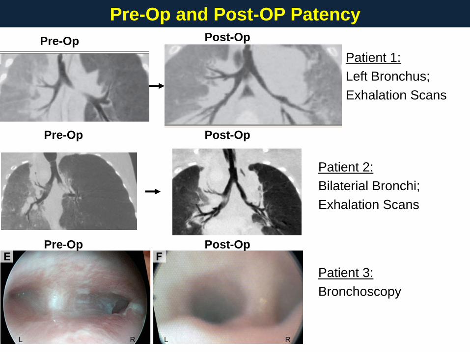
Patient 1: Left Bronchus; Exhalation Scans
Pre-Op and Post-OP Patency
Patient 2: Bilaterial Bronchi; Exhalation Scans
Patient 3: Bronchoscopy
Pre-Op
Post-Op
Post-Op
Post-Op
Pre-Op
Pre-Op

Bronchial Growth in Patients
Hydraulic Diameter Measures Averaged along Bronchus in MIMICS
3 months at surgery 16 months at surgery
5 months at surgery

All Patients Pre- and Post-Op
Patient 1 – 2nd Birthday
Patient 1 – Pre-Op
Patient 2 – First time sitting up
Patient 2 – Pre-op 16 months
Patient 3 – Pre-Op
Patient 3 – Post-Op 2 months

Quality Control: Current & Future

• Powder: Check particle size range; Powder Visual Inspection; Humidity Solid Hygrometer Should be 10% to 35% relative humidity
• Build: Check for errors on build log; visual inspection for part dragging; visual inspection for sintered “islands” when unpack build; stair stepping on parts
• Geometry: Caliper Measures (current); Micro-CT to assess part geometry/density (implementing)
• Mechanical Properties: Standard cylindrical test specimens for modulus; splint specimens opening, compression, bending geometric stiffness (implementing)
Quality Control Checks for Each Build

• For topology optimized (optimized for stiffness/permeability) microstructures, compare designed vs manufactured geometry by microCT (implementing for splint)
Geometry Quality Control
Design/Fabrication Process
Design to Fabricated Strut/Throat Comparison
Fidelity depends on Unit Cell Size & thus Feature resolution; Dias et al, (2014), 36:448-457
2uc: 14-50%; 3uc: 4-30%; 4uc: .3-20%
design∆

Mechanical Testing Quality Control - General Solid Test Cylinder Modulus 1. Affected by Laser scanning
parameters: Bed Temp, Laser Power, Scan Speed 1200-2500 mm/s
2. Anisotropic due to layering Ex = 295.5 ± 4.4 MPa parallel to bed Ey = 292.7 ± 9.9 MPa parallel to bed Ez = 311.7 ± 1.2 Mpa laser direction
Optimized Microstructures 1. Topology optimized for desired
stiffness/permeability 2. Compare FE idealized to laser
sintered mechanically tested 3. Correlation deviates from 1 to 1 as
feature sizes get smaller (< 0.8mm)
Coelho et al, (in press) Med Eng Phys

Mechanical Testing Quality Control - Splint
2
;
( / * *1 ; * * )
(target .1 ;.2 * ; )
(.12 * / .1* )
(.12 * / .2* )
10 /2 /
Ku fNf artery exhalation pressure length mm mm mm
mmKu comp open inner diameter mm
Stiffness in compression N length ID
Stiffness inopening N length OpenAngle
N mmN mm
= ⇒
=
>≈≤≈
Patient 1 - Compression: 128.6 ± 11.8 N/mm; Opening: 2.77 ± 0.26 N/mm; Patient 2 - Compression: 72.2 ± 14.6 N/mm (11mm); Opening: 1.43 ± 0.12 N/mm; 195.8 ± 16.2 N/mm (23mm); Opening: 2.43 ± 0.15 N/mm; Pig Preclinical: Compression: 28.5 ± 1.6 N/mm; Opening: .43 ± 0.05 N/mm; 20% growth over 8 months
Compression: Simulate exhalation loading
Opening: Simulate growth and inhalation loading
Design Target: 1. Withstand arterial
compression & respiration pressure
2. Allow growth

Fatigue & Degradation Quality Control • For resorbable materials, need to determine affect of sintering on fatigue &
degradation
• Sintering doesn’t significantly change/degrade PCL molecular weight prior to implantation; ~40% loss of Mw by 18 months in vivo (spine cage in pig).
• Fatigue properties depend significantly on geometry; Have run spine cages to 5 million cycles in dry environment – need to test in solution

• Developed Laser Sintered, resorbable PCL patient specific splint for treating tracheobronchalmalacia; Successful in 3 patients up to 31 months
• Fabricated topology optimized scaffolds with complex microstructure • Splints with 0.4 to 2.8 N/mm opening stiffness allowed growth in patients and
preclinical pig model; 28 to 195 N/mm compression stiffness protects malacic airway
• Laser parameters (scan speed, bed temp, scan power, particle size) significantly affect device geometry, mechanical properties (stiffness, strength, fatigue) & degradation (need to be tested)
• Ability to meet geometric and mechanical requirements depends on how
close feature size is to minimum resolvable sintering feature -> closer to minimum feature size will mean larger deviation between design & actual properties
Conclusions

• Glenn Green, MD collaborator on tracheal splint; tracheal splint surgery • David Zopf, MD; Robert Morrison, MD; tracheal splint • Will Giannobile, DDS, PhD – Periodontal Scaffold • Giulio Rasperini, DDS – Periodontal scaffold • Richard Ohye, MD – tracheal splint (surgery) • Marc Nelson, MD – tracheal splint(referring) • Chia-Ying Lin, PhD cervical spine fusion • Colleen Flanagan, MSE - Splint SLS manufacture • Annie Mitsak, PhD; Eiji Saito PhD • Matthew Wheeler, PhD collaborator on large animal models ADSC • Jonathon Mosley, Dr. Chanaka Rabel, Aaron Maki – Animal Surgeries • Supported by the NIH and a MICHR grant
Acknowledgments