laser scanning: a new method for recording and documentation
TRANSCRIPT

Workshop – Archaeological Surveys WSA1 Recording Methods George Vozikis, Alexander Haring, Evangelos Vozikis and Karl Kraus WSA1.4 Laser Scanning: A New Method for Recording and Documentation in Archaeology FIG Working Week 2004 Athens, Greece, May 22-27, 2004
1/16
Laser Scanning: A New Method for Recording and Documentation in Archaeology
George VOZIKIS, Alexander HARING, Evangelos VOZIKIS and
Karl KRAUS, Austria/Greece
Key words: Laser scanning, Photogrammetry, Archaeology SUMMARY (Stereo-) Close-range photogrammetry has been the main tool in the field of archaeological documentation for many decades. Hence, it is a well-established technique, whereas laser scanning is a rather new method for three dimensional object modelling. Since both methods have their advantages and disadvantages, the goal is to extract the positive aspects of each, in order to decide which method is suitable for a certain application. This paper presents the characteristics of laser scanning technology, based on two examples. The first one is the statue of Marc Anton in the Vienna city centre, depicting Marc Anton sitting on a chariot pulled by three lions. Its approximate size is 2.5m x 5m and its height is about 3m. The extents of the second example are much bigger: the ancient theatre of Dionysus, located on the southern slope of the Acropolis rock in Athens. It comprises one of the most significant restoration programs of the Greek Ministry of Culture since 1984. We will focus in this paper on the main steps of the 'laser-scanning' processing chain; starting from the acquisition of the objects (data capture methods) and ending with the evaluation of the computed three-dimensional models. This includes the registration of different sensor positions, which is a necessary step in order to cover all parts of the surveyed object: each sensor position is described through an individual, local coordinate system and is being transformed into one global, object coordinate system using hybrid adjustment techniques. Also, noise elimination and gross error detection methods are being discussed, as well as problems that appear when dealing with huge data sets. Furthermore, experiences of combining the techniques of photogrammetry and laser scanning are presented. ZUSAMMENFASSUNG Die Aufnahme und Dokumentation von archaeologischen Objekten wird seit vielen Jahren mittels Stereo-Nahbereichsphotogrammetrie durchgefuehrt. Es ist eine gaengige und wohl bekannte Methode im Vergleich zur der jungen Laserscanner-Technologie. Beide dieser Methoden besitzen gewisse Vor- und Nachteile, welche durch diese Arbeit aufgezeigt werden sollen. Es wird das Prinzip des Laserscanners anhand zweier Beispiele erlaeutert. Das erste Beispiel ist die Statue des Marc Anton, die sich in der Wiener Innenstadt befindet und deren Ausmasse ca. 2.5m x 5m mit einer Hoehe von 3m sind. Im Vergleich dazu, handelt es sich bei dem zweiten Beispiel um ein wesentlich groesseres Objekt, das aufgenommen und

Workshop – Archaeological Surveys WSA1 Recording Methods George Vozikis, Alexander Haring, Evangelos Vozikis and Karl Kraus WSA1.4 Laser Scanning: A New Method for Recording and Documentation in Archaeology FIG Working Week 2004 Athens, Greece, May 22-27, 2004
2/16
ausgewertet wurde: das antike Dionysus Theater, das sich am suedlichen Hang des Akropolis-Felsen in Athen befindet. Es ist seit 1984 Teil eines der wichtigsten Restaurierungsprogramme des griechischen Kulturministeriums. In dieser Publikation werden die Hauptschritte der Arbeitskette vorgestellt: von der Datenaufnahme der Objekte mit dem Laserscanner, bis zum berechneten dreidimensionalen Oberflaechenmodell. Es werden auch Methoden zur Rauschunterdrueckung und groben Fehlersuche vorgestellt, sowie Probleme die waehrend der Auswertung entstanden sind.

Workshop – Archaeological Surveys WSA1 Recording Methods George Vozikis, Alexander Haring, Evangelos Vozikis and Karl Kraus WSA1.4 Laser Scanning: A New Method for Recording and Documentation in Archaeology FIG Working Week 2004 Athens, Greece, May 22-27, 2004
3/16
Laser Scanning: A New Method for Recording and Documentation in Archaeology
George VOZIKIS, Alexander HARING, Evangelos VOZIKIS
and Karl KRAUS, Austria/Greece 1. INTRODUCTION Laser scanning technology, both terrestrial and airborne, has encountered great technological advance during past few years. It gives us the opportunity to acquire great amounts of precisely measured data in very short time. The great challenge is to deal with these huge data-sets thoroughly and produce a competent and rather automated workflow, from data capture up to the desired product. This product comprises most of the times a Digital Surface Model (DSM) of the investigated object. Once the DSM is created many follow-up products can be derived without difficulties. If compared to traditional terrestrial close-range photogrammetry, many advantages (but also some disadvantages) can be found when looking at this new 'surveying' method. It seems that the combination of both techniques will lead to the best possible results. This paper describes two quite different case studies, which were carried out using laser scanner technology. For each of the projects, different laser scanners with different specifications were used and also individual evaluation techniques were applied. The first case presented in this paper is the Marc Anton sculpture located in the Vienna City centre and was carried out at the Institute of Photogrammetry and Remotes Sensing of Vienna University of Technology. Here lots attention was paid on automated methods in order to eliminate gross errors and noise of the measurements. The ancient theatre of Dionysus, which is situated near the Acropolis in Athens is the second example discussed in this paper. Here, the scanning and the evaluation of the data were carried out by the company GEOMET Ltd. (Athens, Greece) in cooperation with the Hellenic Ministry of Culture. This project focused on combining traditional terrestrial photogrammetry together with laser scanning technology. The two presented case studies are rather different (not only in their geometric extents but also regarding the application area) and should give a good insight in the capabilities of using laser scanning techniques for documenting archaeological sites.

Workshop – Archaeological Surveys WSA1 Recording Methods George Vozikis, Alexander Haring, Evangelos Vozikis and Karl Kraus WSA1.4 Laser Scanning: A New Method for Recording and Documentation in Archaeology FIG Working Week 2004 Athens, Greece, May 22-27, 2004
4/16
2. PRINCIPLES OF LASER SCANNING
A terrestrial, stationary laser scanner requires distraction mechanisms in two different directions for surveying a certain region of the object of investigation. These two directions can be considered as vertical and horizontal. The modulated light beam travels from the electronic unit (Fig.1, A) and hits the optical element (Fig.1, D), which is rotating with large velocity. On the surface of this optical unit (which behaves like a mirror) the beam is reflected and exits the laser scanning device with a specific angle ζ (Fig.1, B). Once the scanner has finished acquiring this ζ-profile the upper part of the scanner (Fig.1, C) rotates with a very small angle (∆α) around the vertical axis in order to start capturing the next, adjacent ζ-profile (Kraus, 2004). Usually, the object is scanned from different scan positions in order to completely cover its surface. It is recommended that the different scans (point clouds) have small overlapping areas on the edges, which is useful for a precise merging of multiple scans. The
coordinates of the scan positions can be measured by using dGPS (differential Global Positioning System) or other surveying techniques. For each view point one gets a huge cloud of points, where each point is described through the polar coordinates α, ζ and d (measured distance to the spot of the reflected beam on the object). The achievable measuring and registration accuracy of these three variables together with the acquisition speed, the maximal / minimal scanning range as well as the total (possible) viewing angle comprise the major (quality-) characteristics of a laser scanner. The newer generation of laser scanners not only captures information regarding the geometric positions, but additionally registers a value of radiometric intensities for each points. Hence together with the 'distance-image' (which describes the geometric location of each point) also an 'intensity image' referring to the scanned area is created. The first processing step after data acquisition is the so-called geo-referencing of each scan (in Computer Vision also referred to as registration). When speaking of direct geo-referencing it is obligatory to know the (global) coordinates (e.g. obtained by GPS) and the corresponding orientation angles at each scanner position. Since for every measured point a set of polar coordinates is obtained the corresponding coordinates in the global system can easily be derived. Of course the quality of the resulting point coordinates strongly depends on the accuracy of the orientation and positioning elements of the scanner.
Figure 1: Principle of a Laser Scanner

Workshop – Archaeological Surveys WSA1 Recording Methods George Vozikis, Alexander Haring, Evangelos Vozikis and Karl Kraus WSA1.4 Laser Scanning: A New Method for Recording and Documentation in Archaeology FIG Working Week 2004 Athens, Greece, May 22-27, 2004
5/16
In case the scanner position and orientation are unknown, they have to be indirectly computed with the help of ground control points (GCPs). This process is called indirect geo-referencing (or indirect sensor orientation). Usually, retro-reflective marks are used as GCPs and can be automatically located in the intensity image since they have unique patterns with very high contrast. For calculating the six orientation parameters (scanner position and orientation) of each scan, at least three GCPs are needed in each scan (Kraus, 2004). For merging the point clouds of diverse scans tie-points are needed. Most of the times, these are also retro-reflective marks (with unknown coordinates) and can be located automatically by the system during the evaluation process. 3. STATUE OF MARC ANTON The Marc Anton sculpture, which is situated in the city of Vienna, shows the Roman commander and statesman Marcus Antonius sitting on a chariot and being pulled by three lions (Fig.2a). Next to the chariot, there is a forth lion (Fig.2b). The object consists of a socket and the actual sculpture. The socket has an approximate size of 5m by 2.5m and a height of 0.8m. The highest point (Marc Anton's head) is about 3m above the ground. The object's surface contains numerous regions with high detail (e.g. the lions' manes, Marc Anton's face and clothing). Some holes between the spokes of the chariot's wheels increase the surface's complexity. Due to the overall complex structure, occlusions can not be avoided and some areas can not be acquired without tremendous effort. So, in order to keep acquisition time within a limit, some data gaps (e.g. the underside regions of the lions' bodies) had to be accepted.
3.1 Data Acquisition For the acquisition of the object, the laser scanner Riegl LMS-Z360 (Riegl, 2003) was used. Additionally, images were taken using the digital camera Kodak Professional DCS 460c (Kodak, 2003). The laser scanner system allows full 360° scans with a vertical angle field of up to 90°. Measurement rates up to 12,000 points per second are possible. Distance measurement is based on the time-of-flight method, the single shot accuracy is ±12mm. The laser (near-
Figure 2a, 2b: Marc-Anton sculpture at the Viennese Secession
Workshop – Archaeological Surveys WSA1 Recording Methods George Vozikis, Alexander Haring, Evangelos Vozikis and Karl Kraus WSA1.4 Laser Scanning: A New Method for Recording and Documentation in Archaeology FIG Working Week 2004 Athens, Greece, May 22-27, 2004
6/16
infrared) has a beam divergence of 2mrad. For natural targets, distances between 1m and 200m can be measured. The digital camera Kodak DCS 460c has a CCD array with 3072 x 2048 pixels with a pixel size of 9µm. 50% of the pixels are sensitive to green radiation, 25% are to red and blue radiation, respectively. By colour interpolation, a RGB-image with 3060 x 2036 pixels results. A 28mm lens was used, which corresponds to a pixel size on the object of about 1/3000 of the distance. Before data capturing, 29 retro-reflecting targets (quadratic foils and cylinders) were located on the sculpture itself and its periphery, serving as tie points between the scans and the images. The object was scanned from 10 positions. At each of those positions, a 360°-panorama scan as well as a detail scan was performed. The panorama scans with their rather coarse angle
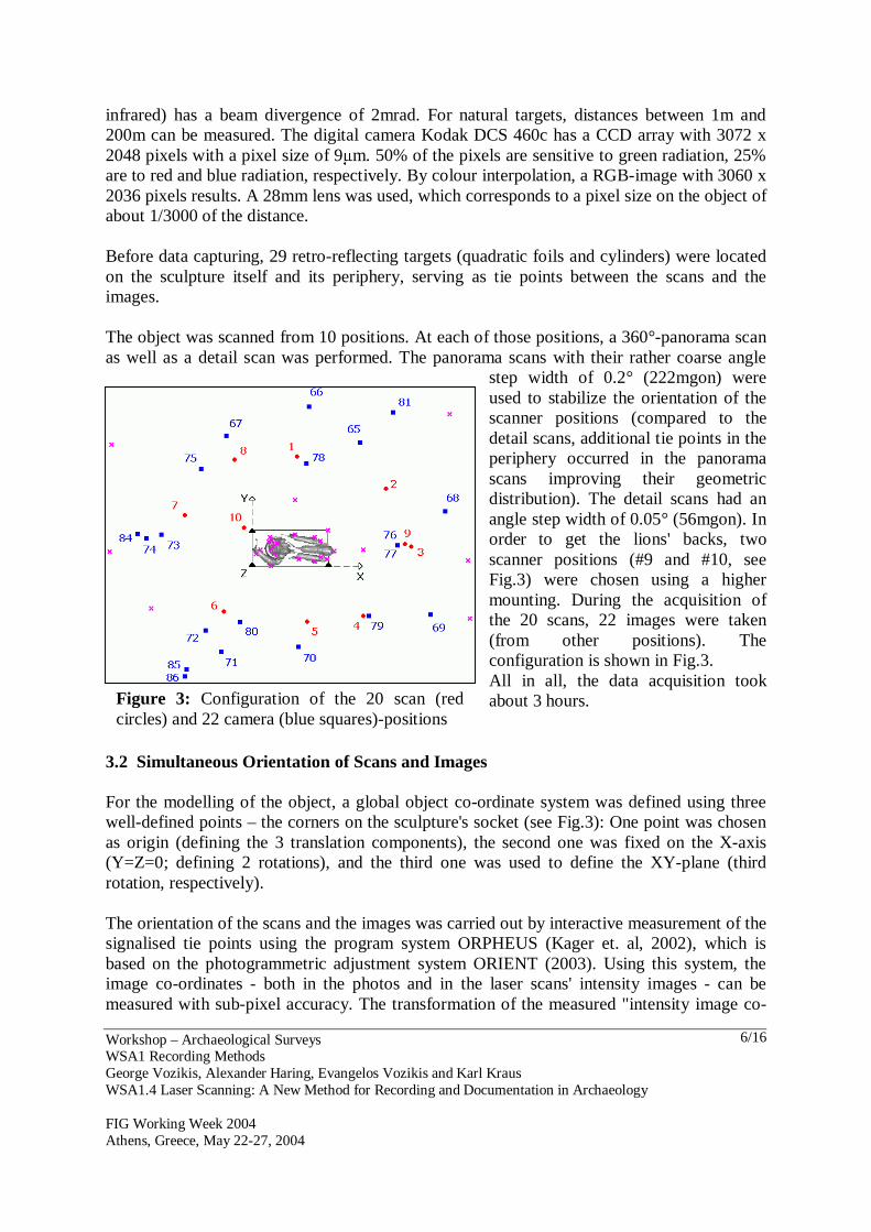
step width of 0.2° (222mgon) were used to stabilize the orientation of the scanner positions (compared to the detail scans, additional tie points in the periphery occurred in the panorama scans improving their geometric distribution). The detail scans had an angle step width of 0.05° (56mgon). In order to get the lions' backs, two scanner positions (#9 and #10, see Fig.3) were chosen using a higher mounting. During the acquisition of the 20 scans, 22 images were taken (from other positions). The configuration is shown in Fig.3. All in all, the data acquisition took about 3 hours.
3.2 Simultaneous Orientation of Scans and Images For the modelling of the object, a global object co-ordinate system was defined using three well-defined points – the corners on the sculpture's socket (see Fig.3): One point was chosen as origin (defining the 3 translation components), the second one was fixed on the X-axis (Y=Z=0; defining 2 rotations), and the third one was used to define the XY-plane (third rotation, respectively). The orientation of the scans and the images was carried out by interactive measurement of the signalised tie points using the program system ORPHEUS (Kager et. al, 2002), which is based on the photogrammetric adjustment system ORIENT (2003). Using this system, the image co-ordinates - both in the photos and in the laser scans' intensity images - can be measured with sub-pixel accuracy. The transformation of the measured "intensity image co-
Figure 3: Configuration of the 20 scan (red circles) and 22 camera (blue squares)-positions

Workshop – Archaeological Surveys WSA1 Recording Methods George Vozikis, Alexander Haring, Evangelos Vozikis and Karl Kraus WSA1.4 Laser Scanning: A New Method for Recording and Documentation in Archaeology FIG Working Week 2004 Athens, Greece, May 22-27, 2004
7/16
ordinates" into polar observations is done automatically using bilinear interpolation (Kraus, 1996). In order to orient the scans and the images simultaneously, a hybrid adjustment was performed. The original observations still contained gross errors due to erroneous distance measurement near the silhouette (especially in the coarse panorama scans). These erroneous observations had to be detected. This was done using the following strategy: In the first step, the residuals were analysed. Thus, observations with very gross distance errors (>0.5m) could be easily detected and eliminated. In the second step, the robust estimation method was performed. This method is well suited to detect "medium-sized" gross errors. Finally, "small" gross errors were eliminated by data snooping (for details see Kraus, 1996 or Kager et al., 2002).
Table 1: Balance of the Adjustment
Number of observations in the 20 intensity images: 819
Number of observations in the 22 photos: 508
Number of fictitious observations (“observed date elements”): 6
Number of original observations: Σ= 1333
Number of distances that were eliminated during residual analysis: -33
Number of observations before robust estimation: Σ= 1300
Number of observations that were eliminated after robust estimation/data snooping: -62
Number of observations: Σ= 1238
Number of orientation parameters to be determined (32 positions each with 6 192
Number of point co-ordinates to be determined (30 points): 90
Number of date-defining point co-ordinates to be determined (3 points): 9
Number of unknowns: Σ= 291 Redundancy: 947
The balance of the adjustment is shown in table 1. Despite the elimination of 95 observations there is still a high redundancy. In order to improve the stochastic model, a variance component analysis was performed in the course of data snooping. For this purpose, 7 observation groups with individual stochastic parameters were formed. In order to get meaningful accuracy values, a free network adjustment was performed. When regarding table 2, one can recognize that the accuracy of the tie points, which are situated directly on the sculpture, is much higher than that of the peripheral ones. The reason is that - compared to the peripheral tie points - the central tie points could be more often observed (and those observations were done from many different directions).

Workshop – Archaeological Surveys WSA1 Recording Methods George Vozikis, Alexander Haring, Evangelos Vozikis and Karl Kraus WSA1.4 Laser Scanning: A New Method for Recording and Documentation in Archaeology FIG Working Week 2004 Athens, Greece, May 22-27, 2004
8/16
Table 2: Average Accuracies of the Unknowns Determined from the Free Network Adjustment Accuracy of position Accuracy of angles dX [mm] dY [mm] dZ [mm] dω[mgon] dϕ[mgon] dκ[mgon]
Laser scans 1.9 1.8 2.9 38 26 15
dX [mm] dY [mm] dZ [mm] dα[mgon] dζ[mgon] dκ[mgon]
Photos 2.4 2.2 2.8 17 20 17
dX [mm] dY [mm] dZ [mm]
Tie points (on the object) 0.7 0.7 0.6
Tie points (periphery) 3.3 3.1 3.5
All tie points 1.5 1.5 1.5
Finally, the following interesting question was examined: To what extent do the accuracies deteriorate if the observations made in the photos were not used (i.e. a pure adjustment of the laser scans)? The answer to this question is given by table 3. The accuracies of the scans' orientation parameters are hardly affected. In the same way, the accuracies of the peripheral tie points are almost not affected when leaving out the photo observations. However, the tie points situated on the sculpture suffer severe accuracy losses (standard deviation three times higher than before!). This can be explained by the fact that those tie points were mainly observed in the high-resolution photos, where they could be identified very precisely. Table 3: Adjustment Without Using the Photo Observations (the corresponding Values of the Hybrid
Adjustment are Shown in Round Brackets)
Balance: Number of observations 749 (1238)
Number of unknowns 159 (291)
Redundancy 590 (947)
Accuracies of the unknowns: dX [mm] dY [mm] dZ [mm] dω[mgon] dϕ[mgon] dκ[mgon]
Laser scans 2.1 (1.9) 2.1 (1.8) 3.2 (2.9) 40 (38) 27 (26) 15 (15) dX [mm] dY [mm] dZ [mm]
Tie points (on the object) 1.8 (0.7) 2.2 (0.7) 2.3 (0.7)
Tie points (periphery) 3.9 (3.3) 3.6 (3.1) 5.1 (3.5)
All tie points 2.5 (1.5)
2.6 (1.5) 3.2 (1.5)
3.3 Modelling of the Object's Surface The modelling of the sculpture was based on the 10 detail scans. The modelling software package Geomagic Studio version 5.0 (Raindrop Geomagic, 2003) was used, which allows the processing of 3D point clouds, the generation of a triangulated surface (polygonal model), and even the calculation of a NURBS (Non-Uniform Rational B-Splines) representation of

Workshop – Archaeological Surveys WSA1 Recording Methods George Vozikis, Alexander Haring, Evangelos Vozikis and Karl Kraus WSA1.4 Laser Scanning: A New Method for Recording and Documentation in Archaeology FIG Working Week 2004 Athens, Greece, May 22-27, 2004
9/16
the object's surface. In Geomagic Studio, there are 3 consecutive phases, namely "Point Phase", "Polygon Phase" and "Shape Phase". First of all, the merged point cloud was restricted to the area of interest using manual selection tools. Thus, the number of points was reduced from ~7.4 million points to ~4.0 million points. Fig.4 shows the 10 scans in different colours. Obviously, there are still erroneous points due to gross distance errors (distance too long), which occurred when measuring near the silhouette (in respect of the scanner positions) because one part of the laser's footprint is already located in the "background" leading to averaged distances. Those erroneous points were eliminated by manual editing. Of course, a better strategy would be to get rid of those points already by analysing the raw data matrix, which contains the points’ topology.
Before further processing, the point cloud (or rather the entire object) was subdivided into socket and actual sculpture. This was done because of the different characteristics of these two parts: The socket has a prismatic form and may be approximated by a set of planes, whereas the sculpture's geometry is very complex and can be represented best by freeform surfaces. A pleasant side effect of this segmentation was the fact that the rather large file size (91MB or 4 million points) could be divided into two circa equally sized smaller files. The two
resulting point clouds were thinned out by uniform sampling. For that purpose, the entire room was split into 1cm-cubes (cells, voxels) and all but one point of each cell was deleted. Thus, the number of points representing the sculpture reduced from ~2 million to ~1.4 million points. As regards the socket, the full-automatic detection of planes provided by the software failed because of the rather high noise. Instead, a semi-automatic function was used, where the user selects a set of points that he supposes to be on a common plane. Starting from this selection, the program determines further points on the plane. Finally, the socket was approximated by 10 planes. The point cloud representing the sculpture had to be filtered strongly since its noise was too high to determine a reasonable triangulation results (see Fig.4). Unfortunately, filtering in Geomagic Studio is available only as black box tool. The user's influence on the filter process
Figure 4: Individually Coloured Point-Clouds

Workshop – Archaeological Surveys WSA1 Recording Methods George Vozikis, Alexander Haring, Evangelos Vozikis and Karl Kraus WSA1.4 Laser Scanning: A New Method for Recording and Documentation in Archaeology FIG Working Week 2004 Athens, Greece, May 22-27, 2004
10/16
is very limited. So, it was necessary to find a suitable filter strategy by systematic trial and error. A single filter step was not sufficient to reduce the noise enough. A strategy of three filter steps including outlier elimination turned out to be a reasonable compromise between noise reduction and detail preservation. After filtering, the point cloud was thinned out using curvature-based sampling, and triangulated. The triangulation was already satisfying for most parts of the surface. However, there were grave errors near data gaps and incompletely captured small structures. So, manual post-processing of the triangulation was necessary, which was a very time-intensive work. Finally, the sculpture's surface was represented by 79,634 points and 155,762 triangles (Fig.5). Fig.6 shows the differences between the newly triangulated and the original point cloud.
Figure 5: Surface Model of the Sculpture Figure 6: Differences: Original minus Final In the final phase (shape phase), a NURBS (Non-Uniform Rational B-Splines) representation of the surface was created. Thus, a so-called patch layout is necessary, i.e. the surface has to be segmented into several areas in order to calculate the NURBS surface. In principle, the patch layout could also be created manually, which would probably lead to much fewer patches. Surely, a manual patch layout might be a little better for certain regions, however, the effort in case of this complex object would be enormous. 4. ANCIENT THEATRE OF DIONYSUS The ancient theatre of Dionysus (Fig.7), which is located on the southern slope of the Acropolis Rock (in Athens), is since 1984 one of the most significant restoration programs of the Ministry of Culture of Greece. The first theatrical installation in the site dates back to the first phase of the sanctuary of Dionysus. Archaeological research has investigated important changes during the late Hellenistic and the Roman eras in the orchestra and the stage building.

Workshop – Archaeological Surveys WSA1 Recording Methods George Vozikis, Alexander Haring, Evangelos Vozikis and Karl Kraus WSA1.4 Laser Scanning: A New Method for Recording and Documentation in Archaeology FIG Working Week 2004 Athens, Greece, May 22-27, 2004
11/16
The task was to survey, document, measure characteristic traces of the area, and produce a highly accurate DSM. The Monument characteristics with the steep slope alterations, the huge marble volume that constitute the stage, isolated areas with detailed restoration and epigraphs, created very difficult conditions for the successful use of traditional surveying and documentation approaches. Hence, due to the particularity of this study, it was decided to use a combination of traditional (terrestrial) photogrammetric, geodetic methods, as well as new Laser Scanner technology. In this study the CYRAX 2500 was employed for the production of the DSM (CYRAX, 2001).
4.1 Photogrammetric Acquisition The idea was to take pictures during the time with the best photo-acquisition conditions in such a way to set off the plasticity of the surfaces, while not preventing readability and distinctness. An appearing problem was the finding of a proper way to get the photogrammetric camera’s elevation. The initial plan was to use the WILD P31 metric camera, in combination with a vehicle having a suitable nacelle. The great differences in elevation of the monument (about 40m) did not permit the implementation of the initial planning. The use of “a balloon” carrying a special construction for holding a camera (Fig.8), which should be lighter than the WILD P31 camera, was chosen as the best technical solution. For that reason, the FUZIFILM GA645W1 camera (which has a smaller format) was chosen, since it is about five times lighter than the WILD P31 metric camera.
Figure 7: Ancient Theatre of Dionysus
Figure 8: Image Acquisition by Using a Balloon

Workshop – Archaeological Surveys WSA1 Recording Methods George Vozikis, Alexander Haring, Evangelos Vozikis and Karl Kraus WSA1.4 Laser Scanning: A New Method for Recording and Documentation in Archaeology FIG Working Week 2004 Athens, Greece, May 22-27, 2004
12/16
The metric FUZIFILM GA645W1 camera (FUJINON, f: 45mm, format 5.5cm x 4.5cm) had been calibrated for geometric and radial distortions. The resulting image scale was about 1:400 at a height of approximately 19m, while the images were acquired in 8 parallel flight strips, with 12 to 14 images obtained per flight strip vertical to the delineated level of the monument, with 70% alongside and 35% wide side overlapping. Altogether 36 GCPs were surveyed using geodetic measurement techniques, which should be sufficient information to achieve good orientation results of the captured ‘balloon’- images. The film digitisation (scanning) was performed at the photogrammetric Scanner Station Leica Helava DSW100, with a pixel size of 12.5µm. The orienting of the models were performed on the photogrammetric digital station Leica Helava DPW770 and DVP. 4.2 Laser Scanner Acquisition A 3D model should be created being able to be processed in a CAD environment, containing the whole elevation information of the theatre’s environment. As mentioned before, a robotic system for automatic point collection was used (Cyrax 2500 Laser Scanner) providing high point density and accuracy (Fig.9). Each laser palm receives a wide range of measurements, while integrated optical encoders record the instantaneous viewing angles. The potential of Cyrax in combination with the ease of its operation and the reduction of time measurement determine a wide range of applications. The most important technical details of the used scanner are given below: − Range up to 150m − Field scanning width of 40° x 40° − Hundred of thousand points in 5-15 min − 6mm point accuracy @ 50m − <1mm resolution (point cloud density) @ 50m − 6mm point diameter @ 50m. Twenty scan positions were used in order to cover the whole area. For each scan, each point distance did not exceed 50-60m so that the final accuracy of the model would be desirable (less than 6mm). The point cloud (Fig.10) was determined in proportion to the object’s detail. For instance, for the orchestra and the stages near the orchestra (the most characteristic area of the monument) the point cloud was 2-3cm, 0.5cm for the relief restoration (statues) and –15cm for the rest of the area.
Figure 9: CYRAX Scanner at the Monument area

Workshop – Archaeological Surveys WSA1 Recording Methods George Vozikis, Alexander Haring, Evangelos Vozikis and Karl Kraus WSA1.4 Laser Scanning: A New Method for Recording and Documentation in Archaeology FIG Working Week 2004 Athens, Greece, May 22-27, 2004
13/16
The whole Theatre’s area was scanned in one day. A built-in camera captures a snapshot of the observed area. This low-resolution image is used to specify the actual area of interest, which will by scanned at the wanted resolution. Additionally, the user has to tell the system the desired point density of the scan.
Figure 10: Sectional View of the Whole Point Cloud
After the data acquisition procedure each scan had its own individual reference system. For the registration procedure (indirect georeferencing), special targets were detected by the system during scanning and their location was estimated with high accuracy. The coordinates of these targets (GCPs) were known in the global reference system, hence the scanner models (individual point clouds) could be transformed into the global reference system. For each scan, at least three of these targets were necessary. The whole registration was performed automatically by Cyclone software (Cyclone, 2001). 4.3 Scanning Results The resulting product of each scan was not a common model (tin, grid), but a point cloud (without constant distance between the points). Additionally, each point was given an additional attribute: spectral colour information for the material that was represented. The point cloud behaved and could be processed as common (photogrammetric) models (change of viewing angle, rotation, translation, etc.) The Theatre’s model was created by the conjunction of twenty different scans using Cyclone. A Visual Basic program was used for reducing the file size to its half without losing any important information, since the original file size was too large for convenient image processing. The new files were imported in Helava DPW770, and converted to a DTM with a grid size of 5-10cm, in order to control and compare these results with those from the photogrammetric evaluation method.

Workshop – Archaeological Surveys WSA1 Recording Methods George Vozikis, Alexander Haring, Evangelos Vozikis and Karl Kraus WSA1.4 Laser Scanning: A New Method for Recording and Documentation in Archaeology FIG Working Week 2004 Athens, Greece, May 22-27, 2004
14/16
The comparison between the Cyrax results and those of photogrammetry and the terrestrial geodetic observations was amazing.
Figure 11: 3D-mesh The differences in X, Y, Z (coordinates in the global reference system) of specific points were of the order of 1-2cm. Thus, it is difficult to estimate whether the orientation error was due to evaluation inaccuracies of the laser scanner data or due to inexact ground-based observation. Moreover, the entire point coverage was quite difficult to be obtained and almost impossible using ground-based observation. For example, the elevation differences between the diverse evaluation methods in the Orchestra’s stones (Fig.12) were less than 9mm.
Figure 12: Orchestra details

Workshop – Archaeological Surveys WSA1 Recording Methods George Vozikis, Alexander Haring, Evangelos Vozikis and Karl Kraus WSA1.4 Laser Scanning: A New Method for Recording and Documentation in Archaeology FIG Working Week 2004 Athens, Greece, May 22-27, 2004
15/16
5. CONCLUSIONS In the first case study (documentation of the statue of Marc Anton), only detail scans were used for surface modelling, whereas the photos were just used to stabilize the block in terms of orientation. Furthermore, edges could be detected easily in digital images, whereas they are problematic regions in laser scanning. So, the photos may compensate the problems occurring in laser scanning. The combined usage of photogrammetry and laser scanning might improve the quality of the surface model. The survey of the Dionysus theatre showed that laser scanning is a very powerful tool concering the short acquisition time and high scanning resulotion. Still there exist some difficulties when it comes to information management of the huge resulting ‘point cloud’ files. The files are enormous in size and each processing step is time-consuming, requiring the maximum of the computer’s capabilities. Summing it up one can say that laser scanning has a great potential in the field of archaeological documentation. But photogrammetric acquisition is many times still necessary as additional information source for achieving the best possible accuracies. REFERENCES Cyclone, 2001. Reference Manual. Cyra Technology Inc. CYRAX 2500, 2001. Reference Manual. Cyra Technology Inc. Kager, H., Rottensteiner, F., Kerschner, M., Stadler, P., 2002. ORPHEUS 3.2.1 User Manual.
Institute for Photogrammetry and Remote Sensing, TU Vienna. Kodak, http://www.kodak.com/global/en/professional/products/cameras/dcs460/dcs460.html,
accessed August 2003. Kraus, K., 1996. Photogrammetry Volume 2, Advanced Methods and Applications, with
contributions by J. Jansa and H. Kager, 4th edition, Dümmler/Bonn. Kraus, K., 2004. Photogrammetrie Band 1, Geometrische Informationen aus Photographien
und Laserscanneraufnahmen. Walter de Gruyter Verlag, Berlin, 2004. 7. Auflage. ORIENT – A universal photogrammetric adjustment system. Product information, Institute
for Photogrammetry and Remote Sensing, TU Vienna. http://www.ipf.tuwien.ac.at/products/produktinfo/orient/html_hjk/orient.html, accessed August 2003.
Raindrop Geomagic. http://www.geomagic.com, accessed August 2003. Riegl, http://www.riegl.com, accessed August 2003. Rottensteiner, F., 2001. Semi-automatic extraction of buildings based on hybrid adjustment
using 3D surface models and management of building data in a TIS. Geowissenschaftliche Mitteilungen, Heft 56, Vienna.

Workshop – Archaeological Surveys WSA1 Recording Methods George Vozikis, Alexander Haring, Evangelos Vozikis and Karl Kraus WSA1.4 Laser Scanning: A New Method for Recording and Documentation in Archaeology FIG Working Week 2004 Athens, Greece, May 22-27, 2004
16/16
CONTACTS George Vozikis Alexander Haring (Christian-Doppler-Labor) Dr. Karl Kraus Institute of Photogrammetry and Remote Sensing – Vienna University of Technology Gusshausstrasse 27-29 A-1040 Vienna AUSTRIA Tel. + 43 1 58801 12201 Fax + 43 1 58801 12299 Email: (gvozikis, ah, kk)@ipf.tuwien.ac.at Web site: www.ipf.tuwien.ac.at Dr. Evangelos Vozikis GEOMET Ltd. 6, Vyronos str. GR-15231 Halandri GREECE Tel. + 30 210 6748540 Fax + 30 210 6753780 Email: [email protected] Web site: www.igd.gr