laser level transmitter - abb group operating instructions | oi-llt100-ena rev. d llt100 laser level...
TRANSCRIPT

LLT100Laser Level Transmitter
Operating Instructions/OI-LLT100-EN Rev. D
The new standard in industrial laser level transmitters
Measurement made easy
Customer benefitsThe LLT100 is specifically made for industrial applications and harsh environments. It provides continuous, non-contact level measurement capabilities for process automation and inventory management in industries such as mining, aggregates, oil & gas, chemicals, food & beverages, power, pulp & paper, pharma, and water & waste water.
Optimize process or inventory management – Precise measurement of any solid or liquid – Independent of material properties
Low cost of ownership – Fast and flexible installation – No maintenance – Single product configuration works in many applications
Main featuresABB brings laser level transmitters to the next level of non-contact measurements by packaging laser ranging technology with the features required by industrial applications. Using a pulsed laser for performing time-of-flight measurements, the LLT100 provides accurate distance measurements while being powered from the 4 – 20 mA loop. Available in aluminum or stainless steel body, it comes with a variety of process interfaces. It can meet the demands of hazardous area locations, as well as high pressure and high temperature applications.
Convenient – Easy setup function – Articulated embedded user interface – 2-wire powered, and HART 7 communication
Reliable – Dust and fog penetration capabilities – Accurate measurements at short and long distances – Explosion-proof class 1, division 1 (zone 1)

The CompanyABB is an established world force in the design and manufacture of measurement products for industrial process control, flow measurement, gas and liquid analysis and environmental applications.
As a part of ABB, a world leader in process automation technology, we offer to our customers application expertise, service and support worldwide.
We are committed to teamwork, high quality manufacturing, advanced technology and unrivaled service and support.
The quality, accuracy and performance of the company’s products result from over 100 years experience, combined with a continuous program of innovative design and development to incorporate the latest technology.
This GuideThis Guide and the accompanying software are copyrighted and all rights are reserved by ABB. This product, including software and documentation, may not be copied, photocopied, reproduced, translated, or reduced, in whole or in part, to any electronic medium or machine-readable format without prior written consent from ABB.
This document contains product specifications and performance statements that may be in conflict with other ABB Inc. published literature, such as product flyers and catalogs. All specifications, product characteristics, and performance statements included in this document are given as indications only. In case of discrepancies between specifications given in this document and specifications given in the official ABB Inc. Product Catalogs, the latter take precedence.
ABB Inc. reserves the right to make changes to the specifications of all equipment and software, and contents of this document, without obligation to notify any person or organization of such changes. Every effort has been made to ensure that the information contained in this document is current and accurate. However, no guarantee is given or implied that the document is error-free or that the information is accurate.
ABB Inc. makes no representations or warranties with regard to the product and instructional and reference materials, including, but not limited to, all implied warranties of merchantability and fitness for a particular purpose.
ABB Inc. does not warrant, guarantee, or make any representations regarding the use, or the results of the use, of any software or written materials in terms of correctness, accuracy, reliability, currentness, or otherwise. ABB Inc. shall not be liable for errors or omissions contained in its software or manuals, any interruptions of service, loss of business or anticipatory profits and/or for incidental or consequential damages in connection with the furnishing, performance or use of these materials, even if ABB Inc. has been advised of the possibility of such damages.
All equipment, software, and manuals are sold as is. The entire risk as to the results and performance of the equipment and software is assumed by the user.
The software or hardware described in this document is furnished under a license and may be used, copied, or disclosed only in accordance with the terms of such license.

OI-LLT100-ENA Rev. D | Operating Instructions iii
Table of Contents
1 Safety ........................................................................ 11.1 Meaning of safety icons and wording ................. 11.2 Personnel ......................................................... 21.3 Electrical........................................................... 21.4 Laser ................................................................ 31.5 Improper use .................................................... 31.6 Technical limit values ......................................... 31.7 Operator liability ................................................ 3
2 Introducing the LLT100 ............................................. 52.1 Purpose of this guide ........................................ 52.2 Overview .......................................................... 5
3 Connecting the LLT100 ............................................. 73.1 Before you start ................................................ 73.2 Requirements ................................................... 73.3 Connecting the instrument................................. 83.4 Grounding the instrument .................................. 93.5 Powering on the instrument ............................. 10
4 Presenting the User Interface ................................. 114.1 LCD interface and keypad ............................... 114.2 Navigating the user interface ........................... 124.3 Accessing menus ............................................ 124.4 Presenting the first level of configuration menus 134.5 Presenting the first level of operator menus ...... 134.6 Introducing HART Communication ................... 13
5 Quick setup ............................................................. 155.1 Introducing the default factory settings ............. 155.2 Setting initial parameters with LCD interface ..... 16
6 Setting up general device parameters .................... 196.1 Protecting access with passwords ................... 196.2 Preventing settings overwrites ......................... 196.3 Setting measurement values ............................ 196.4 Setting measurement value high and low limits . 196.5 Setting up the process value (PV) ..................... 196.6 Setting level calibration points ......................... 206.7 Configuring linearization .................................. 206.8 Setting the level offset ..................................... 216.9 Setting the vessel height ................................. 216.10 Setting the level unit ........................................ 216.11 Setting the sensor offset .................................. 216.12 Selecting the measurement mode .................... 216.13 Configuring filtering options ............................. 21
7 Configuring filtering ................................................ 237.1 Setting the rate unit ......................................... 237.2 Configuring a No Measurement period ............. 237.3 Configuring the median filter ............................ 237.4 Configuring the filling rate ................................ 247.5 Configuring the draining rate ............................ 247.6 Enabling damping ........................................... 24
8 Configuring linearization ......................................... 258.1 Defining linearization ....................................... 258.2 Configuring device linearization ........................ 258.3 Managing linearization tables ........................... 26
9 Configuring the display ........................................... 279.1 Setting the interface language ......................... 279.2 Setting the contrast ......................................... 279.3 Configuring Operator pages ............................. 279.4 Configuring Autoscroll ..................................... 279.5 Selecting the number of decimals .................... 289.6 Setting passwords .......................................... 289.7 Managing display settings ............................... 28
10 Configuring process alarms .................................... 2910.1 Setting failure mode ........................................ 2910.2 Defining alarm delays ...................................... 2910.3 Setting saturation limits ................................... 3010.4 Setting process alarms limits ........................... 3010.5 Managing process alarms settings ................... 30
11 Installing the LLT100 on site ................................... 3111.1 Safety information ........................................... 3111.2 General information ......................................... 3111.3 Environmental considerations .......................... 3111.4 Rotating the LCD ............................................ 3211.5 Rotating the LCD housing................................ 3311.6 Selecting installation material ........................... 3311.7 Aligning the instrument .................................... 3411.8 Installation Do’s and Don’ts ............................. 36
12 Maintenance ........................................................... 3712.1 Cleaning the window (all models BUT hygienic) . 3712.2 Cleaning the window (hygienic model) .............. 37
13 Troubleshooting and service ................................... 4113.1 Identifying the problem .................................... 4113.2 Configuring diagnostic tools ............................ 4113.3 Running simulations ........................................ 4113.4 Accessing diagnostic history............................ 4113.5 Managing alarm display ................................... 42

iv Operating Instructions | OI-LLT100-ENA Rev. D
LLT100Laser level transmitter
13.6 Obtaining software version numbers ................ 4213.7 Managing Instrument Communications ............. 4213.8 Calibrating the 4 – 20 mA current loop .............. 4313.9 Service ........................................................... 4313.10 Disposal ......................................................... 4413.11 Transportation and storage .............................. 44
Appendix A Hazardous Area Consideration & Labels 47Ex Safety aspects and IP Protection (Europe) ............. 47Ex safety aspects and IP protection
(North America) ............................................... 49Specific condition of safe use for ATEX, IECEx, and
cFMus certifications ........................................ 50Instrument labels ...................................................... 51Optional ID tag plates ............................................... 52
Appendix B Accessories ........................................... 53Cooling tube ............................................................. 53External commissioning laser device .......................... 55Dust tube ................................................................. 55Purge ring ................................................................ 55Adjustable pivot bracket ............................................ 56Swivel mount ............................................................ 57Specifications ........................................................... 58
Appendix C Instrument specifications ...................... 59
Appendix D EU Declaration of Conformity ................ 61

OI-LLT100-EN Rev. D | User Guide 1
1 Safety
This section provides an overview of the safety aspects that must be observed when operating the instrument.
The instrument has been constructed in accordance with the state of the art and it is operationally safe. It has been tested and left the factory in perfect working conditions. The information in this guide, as well as the applicable documentation and certificates, must be observed and followed to maintain this condition throughout the period of operation.
Full compliance with the general safety requirements must be observed during operation of the device. In addition to the general information, the individual sections in the manual contain descriptions of processes or procedural instructions with specific safety information.
Only by observing all of the safety information can you reduce to the minimum the risk of hazards for personnel and/or environment. These instructions are intended as an overview and do not contain detailed information on all available models or every conceivable event that may occur during setup, operation, and maintenance work.
For additional information, or in the event of specific problems not covered in detail by these operating instructions, please contact the manufacturer. In addition, ABB declares that the contents of this manual are not part of any prior or existing agreements, commitments, or legal relationships; nor are they intended to amend these.
All obligations of ABB arise from the conditions of the relevant sales agreement, which also contains the solely binding warranty regulations in full. These contractual warranty provisions are neither extended nor limited by the information provided in this manual.
Read this manual carefully before working with the instrument. For personal and system safety, and to obtain optimum performance, make sure that you thoroughly understand the contents of this manual before installing, using, or maintaining the instrument.
1.1 Meaning of safety icons and wording
DANGER SERiouS DAmAGE to hEAlth/RiSk to lifE
DANGER indicates a hazardous situation that, if not avoided, will result in death or serious injury.
WARNiNG DAmAGE to hEAlth/RiSk to lifE
WARNING indicates a hazardous situation that, if not avoided, could result in death or serious injury.
CAutioN DAmAGE to hEAlth
CAUTION indicates a hazardous situation that, if not avoided, could result in minor or moderate injury.
NotiCE
NOTICE indicates information considered important, but not hazard related, that could impact things other than personal injury, like property damage.
hiGh VoltAGE
Indicates the presence of electrical energy at voltages high enough to inflict harm on living organisms.
lASER RADiAtioN
The laser warning icon indicates the presence of a laser related hazard. It also indicates the type of laser in use, its wavelength and its safety class.
ShARp EDGES
Indicates the presence of sharp edges that could cause personal injury if touched.
ElECtRoStAtiC DiSChARGES
Indicates device susceptibility to electrostatic discharges (ESD).
Indicates protective earth terminals which are intended for connection to an external conductor for protection against electrical shock in case of a fault, or the terminal of a protective earth (ground) electrode.
Indicates the presence of direct current.

2 User Guide | OI-LLT100-EN Rev. D
LLT100Laser level transmitter
1.2 Personnel
WARNiNG
Only qualified and authorized specialists should be charged with the installation, electrical connection, commissioning, operation, and maintenance of LLT100 instruments.
These specialists must hold the necessary qualifications, such as training or instruction, to operate and maintain devices or systems in accordance with safety engineering standards regarding electrical circuits, high pressures, aggressive media, and adequate safety systems, based on local national standards such as NEC for USA, National Building Code, etc.
Since the LLT100 may form part of a safety chain, we recommend replacing the device immediately if any defects are detected.
Only use non sparking tools when installing the instrument in hazardous areas.
WARNiNG
The device can be operated at high levels of pressure and with aggressive media. As a result, serious injury or significant property damage may occur if this device is operated incorrectly.
Any process media released may cause severe injuries. Depressurize the pipeline/tank before opening the LLT100 connection.
Provide adequate protection and training against chemicals involved in the work environment.
Carefully plan any installation, modification, or repair before actually proceeding.
1.3 Electrical
Electrical connections may only be established by authorized specialist personnel in accordance with the electrical circuit diagrams. The electrical connection information in the manual must be observed; otherwise, the applicable protection type may be affected. Ground the instrument according to requirements.
In addition, you must observe the relevant safety regulations regarding the installation and operation of electrical systems, and the relevant standards, regulations and guidelines about explosion protection.
WARNiNG
Avoid contact with leads and terminals. Electrical shock could result in death or serious injuries.
Do NOT make electrical connections unless the electrical code designation stamped on the LLT100 data plate matches the classification of the area in which you want to install the LLT100. Failure to comply with this warning can result in fire or explosion.
Use only tools compliant with national insulation standards, like DIN EN 60900.
Only use non sparking tools when installing the instrument in hazardous areas.
During installation, completely power down the 4–20 mA loop for at least 60 seconds, as otherwise it may cause a permanent error.
Figure 1 External protective earth (PE) terminal
1.3.1 Surge protector-equipped terminal block
To ensure proper functioning, ground connection is mandatory for surge protector-equipped instruments.
CAutioN
Test voltage withstand capability can no longer be ensured when this protective circuit is used.
1.3.2 Common mode voltages
The LLT100 with surge protection will not work if exposed to common mode voltage in excess of the maximum allowed supply voltage.
WARNiNG hiGh VoltAGE
Ensure that the equipment or any device or power cord connected to the LLT100 is properly grounded.

OI-LLT100-EN Rev. D | User Guide 3
WARNiNG hiGh VoltAGE
All protective earthing connections (grounding) must be active at all times. The absence of grounding can lead to a potential shock hazard that could result in serious personal injury. If an interruption of the protective earthing connection is suspected, ensure the equipment is not used.
Use the LLT100 ONLY if a properly grounded power source is available in accordance with the local electrical code.
Before using the LLT100, make sure that the appropriate supply voltage is available.
WARNiNG pRopERty DAmAGE
Depending on the model, there may be no EMC protection or protection against accidental contact when the housing cover is open. Therefore, the auxiliary power must be switched off before opening the housing cover.
NotiCE
The presence of noise on the instrument 4 – 20 mA output can be a sign of poor or intermittent grounding, insufficient cable shielding, or noisy power line in the vicinity.
1.4 Laser
lASER RADiAtioN
Invisible laser radiation at 905 nm.
Class 1 laser is safe for all conditions.
The LLT100 uses a Class 1 infrared (905 nm) laser producing an invisible beam that is used to measure distance. A Class 1 laser is safe under all normal operating conditions. This means that the maximum permissible exposure (MPE) cannot be exceeded when viewing a laser with the naked eye or with the help of typical magnifying optics (e.g. telescope, microscope magnifying glass, lenses of any type).
Invisible laser, Class 1 (standard operation)
Wavelength 905 nm
Peak Power 45 W
Average Power 7.1 mW
Pulse Duration (FWHM) 1.8 ns
Pulse Rep Frequency 680 kHz
Pulse Energy 72 nJ
Pulse Train Duration (total) 0.190 ms
Beam Dimension at 30 m 20 cm × 3 cm
Divergence Δ < 0.3°
The LLT100 is designated as a Class 1 laser device during all procedures of operation, as per IEC 60825-1, Ed. 2, 2007. It complies with FDA performance standards for laser products, except for deviations pursuant to Laser Notice No. 50, dated June 24, 2007.
1.5 Improper use
It is prohibited to use the instrument for any, including but not limited to, of the following:
– A climbing aid, e.g., for mounting purposes.
– A support for external loads, e.g., as a support for pipes.
– By adding material, e.g., by painting over the name plate, or welding/soldering on parts.
– By removing material, e.g., by drilling the housing.
Repairs, alterations, and enhancements, or the installation of replacement parts, are only permissible as far as these are described in this manual. Approval by ABB must be requested in writing for any activities beyond this scope. Repairs performed by ABB-authorized centers are excluded from this article.
1.6 Technical limit values
The instrument is designed for use exclusively within the values stated on the name plates and within the technical limit values specified on the data sheets.
Technical limit values that must be observed at all time are:
– The maximum working pressure, ambient working temperature, and maximum process temperature may not be exceeded.
– The housing protection type must be observed.
– The electrical specifications must be observed.
1.7 Operator liability
Prior to using corrosive and abrasive materials for measurement purposes, the operator must check the level of resistance of all instrument parts coming into contact with the materials to be measured.
CAutioN
Prior to using the LLT100, material safety data sheets (MSDS) of all products being monitored must be available at all times for the security of the user.
ABB will gladly support you in selecting the materials, but cannot accept any liability in doing so.
Operators must strictly observe the locally applicable national regulations with regard to installation, function tests, repairs, and maintenance of electrical devices.

This page intentionally left blank

OI-LLT100-EN Rev. D | User Guide 5
2 Introducing the LLT100
The LLT100 is a laser level transmitter that accurately measures level, distance, and position over long ranges in extreme environments. The LLT100 features advanced timing and sophisticated signal processing for pinpoint accuracy when measuring levels of solid or liquid and for positioning applications.
2.1 Purpose of this guide
This user guide is intended for personnel using the LLT100 for routine analysis; it contains installation, user, maintenance, and troubleshooting instructions.
Read this manual carefully before working with the product. For personal and system safety, and for optimum performance, make sure you thoroughly understand the contents of this document before installing, using or maintaining the instrument. This guide does not contain detailed information on all available models or every conceivable event that may occur during setup, operation, and maintenance work.
Servicing on this instrument is to be performed at factory by qualified service personnel only.
No user/operator adjustments inside the LLT100 are necessary or recommended by the manufacturer.
For additional information, or in the event of specific problems not covered in detail in this user guide, please contact the manufacturer. Moreover, ABB declares that the contents of this manual are not part of any prior or existing agreements, commitments, or legal relationships, nor are they intended to amend these.
2.2 Overview
Here is a quick overview of the instrument. From it, you can find out the various parts of the instrument as well as where you can find additional information on the subject elsewhere in this document.
Figure 2 LLT100 with a Class 150 flange
Screwed-on stainless steel plate (see “Instrument labels” on
page 51)
Ex protection mode identification plate (see “Instrument labels” on
page 51)
Instrument name plate (see “Instrument labels” on page 51)
Housing stop tang-screw (see “Rotating the LCD housing”
on page 33)
Blocking screw (see “Aligning the instrument”
on page 34)
External ground connection (see “Grounding the instrument” on page 9)
Instrument LCD (optional) (see “LCD interface and keypad” on page 11)
Housing cover (LCD side) (see “Rotating the LCD” on
page 32)
Housing cover (terminal side) (see “Connecting the instrument” on page 8)

This page intentionally left blank

OI-LLT100-EN Rev. D | User Guide 7
3 Connecting the LLT100
WARNING Serious damage to health / Risk to life
Avoid contact with leads and terminals. Electrical shock could result in death or serious injuries.
Do NOT make electrical connections unless the electrical code designation stamped on the LLT100 data plate matches the classification of the area in which you want to install the LLT100. Failure to comply with this warning can result in fire or explosion.
Use only tools compliant with national insulation standards, like DIN EN 60900.
Only use non sparking tools when installing the instrument in hazardous areas.
During installation, completely power down the 4–20 mA loop for at least 60 seconds, as otherwise it may cause a permanent error.
3.1 Before you start
– Observe all applicable regulations governing electrical installation.
– Only qualified and authorized specialists should be charged with installation, electrical connection, commissioning, operation, and maintenance of LLT100 instruments. These specialists hold the necessary qualifications, such as training or instruction, to operate and maintain devices or systems in accordance with safety engineering standards regarding electrical circuits, high pressures, aggressive media, and adequate safety systems, based on local national standards such as NEC for USA, National Building Code, etc.
– Connections must be established in a de-energized state.
– While working on the circuit, secure the breaker to prevent any accidental power-up.
– For continuous installation protection, a double insulation power supply (5 kV or higher) shall be used for the current loop.
– The power supply shall be equipped with a short circuit protection function and an auto restart.
– To avoid injury or property damage in external installations exposed to lightning, a transient voltage suppression module or galvanic isolator shall be installed, with proper grounding, before entering a building with a cable. Refer to local building code and electrical code for proper practices.
– In an industrial environment where EMIs (electromagnetic interferences) are extremely present, such as in rock quarries, mines, or in large chemical plants, ABB recommends the use of noise filters on the DC power supply to the instrument and on signal isolators’ 4–20 mA output.
– The same power supply can be used for both the 4 – 20 mA loop and the window heater. A second pair of wires shall be used to avoid voltage drops exceeding the LLT100 electrical specifications (see “Typical connections” on page 10).
– Since the LLT100 may form part of a safety chain, we recommend replacing the device immediately if any defects are detected.
3.2 Requirements
3.2.1 Power supply
For signal/power connection, use 18 to 22 AWG twisted, stranded pairs wiring (Ø 0.8 mm2 to 0.35 mm2) up to 5000 feet (1500 meters) in length. Longer loops will require larger wires.
The 4 – 20 mA DC output signal and the DC power supply to the LLT100 are carried by the same pair of wires.
Supply voltage at the instrument terminals must be between 15.5 VDC and 42 VDC. If using 250 Ω for HART, limits are 21 VDC to 42 VDC if there is no other load on the line.
For maximum power supply voltage, refer to the instrument identification plate.
Avoid routing cables with other electrical cables (with inductive load, motors, etc.) or near large electrical equipment.
3.2.2 Cables
WARNING
Cables, cable glands, and unused port plugs must comply with the intended type of protection (e.g. dust proof, flameproof, etc.) and degree of protection (e.g. IP66/IP67 [according to IEC EN 60529] or Type 4X [according to NEMA 250]).
It is the costumers’ responsibility to use appropriate cable glands, screw plugs, lubes and/or sealants for the cable entry ports. ABB does not assume any responsibility for non ATEX- or CE-certified cable glands or adapters that do not meet the above requirements.
The installer assumes responsibility for any other type of sealing medium used.
In the particular case of explosion proof installations, remove the temporary plastic caps and close the unused opening with a plug certified for explosion containment with appropriate rating.
NOTICE
If you plan on using cable glands that are not supplied by ABB, please refer to your supplier’s data sheet for proper installation.
Wires and cable glands shall be rated to at least 90°C.

8 User Guide | OI-LLT100-EN Rev. D
LLT100Laser level transmitter
The LLT100 has a ½-inch NPT/M20 cable gland entry. You must use a ½-inch NPT/M20 cable gland certified to either Ex db or Ex tb (depending on the installation), and rated to at least IP66/IP67. The cable glands supplied by ABB are ATEX- and CE-certified, and meet the above requirements.
These cable glands can only be used with braided shield cables. When installing them, make sure to fold the cable shield over the O-ring which presses the braiding against the inside wall of the body, thus ensuring good contact.
3.3 Connecting the instrument
WARNING
If required by your national electrical code, a circuit breaker or switch in the building installation, marked as the disconnect switch, shall be in close proximity to the equipment and within easy reach of the operator.
WARNING
In an explosion proof/flameproof installation, do not remove the covers while the instrument is energized.
To bring power to the LLT100:
1. Remove the temporary plastic cap from one of the two electrical connection ports (see Figure 3).
2. Remove the housing cover on the “terminals” side (see Figure 3). Refer to the indications on the instrument name plate.
WARNING Property Damage
Depending on the model, there may be no EMC protection or protection against accidental contact when the housing cover is open. Therefore, the auxiliary power must be switched off before opening the housing cover.
NOTICE
After an interval of several weeks, increased force will be required to unscrew the housing cover.
This is not caused by the threads, but rather by the type of gasket used.
WARNING Sharp edges
Do not handle the instrument by the threaded interface. Threaded edges are sharp and could cause personal injuries.
4. Run the cable through the cable gland and the open port.
5. Connect the positive lead to the + terminal, and the negative lead to the – terminal.
Figure 3 Accessing the terminals inside the LLT100
WARNING
The terminal block needs to be replaced if the installation shows any sign of damage resulting from direct or indirect lightning.
6. Plug and seal the electrical ports.
7. (if applicable) Install wiring with a drip loop. Arrange the drip loop so that the bottom is lower than the conduit connections and the LLT100 housing.
8. Put back the housing cover. Turn it so as to seat the O-ring into the housing, then continue to tighten by hand until the cover contacts the housing metal-to-metal.
WARNING Securing the housing cover in flameproof/explosion proof areas
Both faces of the electronics housing feature a M4 locking screw (hex-head socket screw) on the bottom side (see Figure 5).
– Install the housing cover on the housing by hand-tightening it.
– Turn the locking screw counterclockwise to secure the housing cover. This involves unscrewing the screw until its head stops at the housing cover.
9. Once the installation is complete, make sure that electrical ports are properly sealed against all types of fluid ingress (rain and/or corrosive vapors or gases).
Cable gland
“Terminals” cover
Unused electrical connection port with standard metal cap

OI-LLT100-EN Rev. D | User Guide 9
3.4 Grounding the instrument
The LLT100 must be grounded in accordance with national and local electrical codes, using the grounding terminal (PE) by means of a short connection with an equipotential bonding. The equipotential bonding conductor must have a maximal cross-section of 4 mm2.
Star or daisy chains are not allowed under any circumstances.
Protective earth (PE) terminals are available inside and outside the instrument housing (see Figure 5 on page 9). These terminals are electrically connected.
When grounding the LLT100 with a shielded wire, connect the wire to the PE terminal located inside the LLT100 housing. That shield wire should only be grounded at one end, not both.
If using the external PE terminal, you MUST connect the wire to the monitored vessel.
The most effective LLT100 case grounding method is direct connection to earth ground with an impedance of 5 mOhm or less.
3.4.1
Figure 4 External protective earth (PE) terminal
Surge protector-equipped terminal block
To ensure proper functioning, ground connection is mandatory for surge protector-equipped instruments. An overloaded instrument must be de-energized for at least 5 seconds.
CAUTION
Test voltage withstand capability can no longer be ensured when this protective circuit is used.
Outside installations or installations exposed directly or indirectly to lightning discharges shall have a secondary lightning protection module. Use of a protected terminal block in combination with a lightning arrestor module, both properly grounded, is mandatory for the continuous protection of installations and users. Refer to local building code and electrical code for proper practices.
3.4.2 Common mode voltages
The LLT100 with surge protection will not work if exposed to common mode voltage in excess of the maximum allowed supply voltage.
Figure 5 LLT100 terminal compartment (back of LLT100 unit, with cover off)
Internal PE terminal
M4 cover locking screw
External DC supply for lens heater option: +24 V, 3 W
External PE terminal0 V (return)
Connectors available ONLY on LLT100 with heater option (2+2 wires)
External meter (optional)
Pos ( + )
Neg ( – )

10 User Guide | OI-LLT100-EN Rev. D
LLT100Laser level transmitter
3.5 Powering on the instrument
Once the LLT100 has been connected, you energize it by turning on the power source.
Before turning on the power source, check the following:
– Covers’ installation
– Locking screws tightness
– Process connections
– Electrical connections
The LLT100 can then be put into operation.
NOTICE
Brief interruptions in power supply will result in initialization of the electronics (the embedded software restarts).
3.5.1 Typical connections
Figure 6 2 + 2 wires
Figure 7 2 + 2 wires (with heater option)
Figure 8 2 wires

OI-LLT100-EN Rev. D | User Guide 11
4 Presenting the User Interface
4.1 LCD interface and keypad
The integrated LCD can be used to configure the LLT100 and to visualize process measured variables.
Four arrow keys ( , , , ) are available for the menu-driven configuration.
– A scroll bar shows the relative position of the currently selected menu item within the menu.
– The Left and Right arrow keys have many functions (see Table 1). The meaning of these keys is displayed in the LCD above the respective key.
– You can browse through the menu or select numbers of a parameter value using the Up or Down arrow keys ( , ).
Figure 9 Typical User screen (left) and Configuration screen (right)
Table 1: Left and Right arrow key functions
Left arrow key ( ) Meaning
Exit Exit menu
Back Back one sub-menu
CancelExit without saving the selected parameter value
NextSelect next position for entering numerical values or letters
Right arrow key ( ) Meaning
Select Select sub-menu/parameter
Edit Edit parameter
OKSave selected parameter and display stored parameter value
Menu item number
Left arrow key
Up arrow keyDown arrow key
Right arrow key
Menu/sub-menu name
Menu title
Actions performed by pressing the arrow key underneath
Access to User menus
Access to Configuration menus
Scroll bar

12 User Guide | OI-LLT100-EN Rev. D
LLT100Laser level transmitter
Figure 11 Selecting a value to edit
Figure 12 Setting a value
4.3 Accessing menus
Upon selecting the configuration menu icon on the main screen, the interface displays a selection of four access levels: Read Only, Standard, Advanced, and Service.
Figure 13 The Access Level menu
All access levels but read-only require a password (if defined). When selecting an access level, you will be asked for your password. By entering the proper password, you will gain access to the features associated with that access level.
For more information on setting passwords, see “Protecting access with passwords” on page 19.
NOTICE
ABB recommends the Advanced setting as it provides the best balance of access and security.
4.2 Navigating the user interface
There are two operations that you can do when navigating the user interface. You can select an existing option, or edit a value.
4.2.1 Selecting an option
You can select options, but you can not modify them. This is the easiest operation to perform:
1. Using the four arrow keys, move left or right, up or down within a menu.
2. Once you find the option that you want to set, highlight it by using the arrow keys.
3. Press OK. The highlighted option is selected and effective immediately.
4. Press Back repeatedly to exit the menu.
Figure 10 Selecting an existing option
4.2.2 Setting a value
Contrary to options, you can modify values.
1. Using the four arrow keys, move left or right, up or down within a menu.
2. Once you find the value that you want to modify, select it with the arrow keys and press Edit.
3. In the Edit screen, use the Left arrow key to move from left to right over the editable values.
4. Once you are on the value that you want to modify, press the Up or Down arrow key to increase or decrease the highlighted value. Modify all necessary values as such.
5. Once you are done modifying values, press OK. The modified value becomes effective immediately.
6. Press Back repeatedly to exit the menu.
Pressing Next highlights the next value to the right

OI-LLT100-EN Rev. D | User Guide 13
4.4 Presenting the first level of configuration menus
Once you enter in the configuration menus, pressing the Down arrow key will navigate through the various menus in the following order:
– Easy Setup
– Device Setup
– Display
– Process Alarm
– Calibrate
– Diagnostics
– Device Info
– Communication
4.5 Presenting the first level of operator menus
Once you enter in the operator menus, pressing the Down arrow key will navigate through the various menus in the following order:
– Diagnostics
– Operator Page 1
– Operator Page 2
– Operator Page 3
– Operator Page 4
– Signals View
4.6 Introducing HART Communication
The HART communication protocol (Highway Addressable Remote Transducer) is a hybrid analog and digital industrial automation protocol. Its most notable advantage is that it allows remote configuration of LLT100 instruments over legacy 4 – 20 mA analog device current loops, sharing the pair of wires used by analog-only host systems.
ABB provides a HART communication package for the LLT100. Once installed in your preferred HART application, it will allow communication with your LLT100 instruments.
The ABB HART communication package (RevXX.XX.XX_XX.XX.XX) is located in the folder whose name ends with DTM_LLT100_HART_Laser_Level.
NOTICE
The communication board for HART (behind the interface board) can not be replaced in the field, and can not be moved between LLT100 instruments. In case of failure, the LLT100 instrument must be sent back to ABB for calibration and repair.
Figure 14 Typical DTM (HART) screen for the LLT100

This page intentionally left blank

OI-LLT100-EN Rev. D | User Guide 15
5.1 Introducing the default factory settings
The LLT100 is delivered with the following default settings:
Parameter Factory settingMeasurement mode Standard
Vessel height 200 m
Vessel empty (LRV) 0.0
Vessel full (URV) Vessel height
Damping 1 second
No-measurement period 15 seconds
4 – 20 mA output (PV) Level
PV unit Meter
LLT100 failure (alarm) High (21 mA)
5 Quick setup
Figure 15 General model
Sensor offset
Vessel height
Vessel full (URV)
Vessel empty (LRV)
Ullage
Level
The LLT100 can be configured with the integrated, keypad-controlled and menu-driven LCD user interface.
Before setting up your LLT100 instrument, it is important to know which value is associated with which setting. Figure 15 illustrates these values and settings.

16 User Guide | OI-LLT100-EN Rev. D
LLT100Laser level transmitter
5.2 Setting initial parameters with LCD interface
Once you powered on the LLT100, you can set the basic parameters from the Easy Setup configuration menu. This is one reason why the Advanced mode is strongly recommended: it allows for configuration of every function in the instrument.
5.2.1 Setting level or ullage parameters
1. Once the LLT100 is on, access Easy Setup in the configuration menus and press Select.
2. Select the interface language and press Next. English is selected by default.
3. Select the measurement mode and press Next.
Standard is selected by default. You select the measurement mode based on the intended application of the instrument being configured (for more information, see Table 2 on page 17).
4. Select the level unit and press Next. This is the unit used in level and ullage measurements, and when calculating volumes.
5. Edit the vessel height (URP, or “ullage reference point”) so that it corresponds to the height of the vessel to be monitored (for more information, see “General model” on page 15).
6. Edit the sensor offset (for more information, see “Setting the sensor offset” on page 21).
7. Select the output type for the 4 – 20 mA process value (PV).
8. Edit the Vessel Empty (LRV, or lower reference value) level (4 mA).
9. Edit the Vessel Full (URV, or upper reference value) level (20 mA). The default value is the vessel height entered previously.
10. (if necessary) Enable the Filling Rate feature (for more information on the filling rate feature, see section 7.4 “Configuring the filling rate” on page 24).
11. (if necessary) Create a tag for the instrument. This “tag”, comprised of alphanumeric characters, is intended to simplify identifying the location of the LLT100 (on the network, in the plant, etc.)
12. Once all Easy Setup parameters have been set, press Next to exit the Easy Setup menu and go back to the default Operator page.
5.2.2 Setting volume parameters
1. Once the LLT100 is on, access Easy Setup in the configuration menus and press Select.
2. Select the interface language and press Next. English is selected by default.
3. Select the measurement mode and press Next.
Standard is selected by default. You select the measurement mode based on the intended application of the instrument being configured (for more information, see Table 2 on page 17).
4. Select the level unit and press Next. This is the unit used in level and ullage measurements, and when calculating volumes.
5. Edit the vessel height (URP, or “ullage reference point”) so that it corresponds to the height of the vessel to be monitored (for more information, see “General model” on page 15).
6. Edit the sensor offset (for more information, see “Setting the sensor offset” on page 21).
7. Select Volume for the 4 – 20 mA process value (PV) output type .
8. Select the unit for the Volume output. The liter (l) is the default value, but other volume units are available.
9. Edit the minimum volume. The default value is 0.
10. Edit the maximum volume. The default value is 1 000 000 liters (or the equivalent in the unit of your choice).
11. (if necessary) Enable the Filling Rate feature (for more information on the filling rate feature, see section 7.4 “Configuring the filling rate” on page 24).
12. (if necessary) Create a tag for the instrument. This “tag”, comprised of alphanumeric characters, is intended to simplify identifying the location of the LLT100 (on the network, in the plant, etc.)
13. Once you have configured the initial volume measurement parameters, you still need to setup your linearization table in the Device Setup menu (8 “Configuring linearization” on page 25) as requested at the end of the Easy Setup menu.
14. Once all Easy Setup parameters have been set, press Next to exit the Easy Setup menu and go back to the default Operator page.

OI-LLT100-EN Rev. D | User Guide 17
Table 2: Measurement modes
Mode Description ApplicationStandard This mode is designed for maximum precision under regular
operating conditions.Use for most solid applications and opaque liquid applications where neither dust nor vapor is present.
Clear Liquid This mode corresponds to the standard measurement mode with an additional bottom-of-the-tank detection algorithm.
Use for transparent liquid applications in which the bottom of the tank is visible through the liquid surface.
Positioning This mode features a special calibration designed to work with retroreflector panel targets provided by ABB. It also features an enhanced double-reflection detection algorithm.
Use for positioning applications where the sensor aims at a highly-reflective retroreflector panel.
Note: Only use when the target is a retroreflector panel. For positioning applications with other types of targets, use the standard measurement mode.
Dust and Vapor This mode uses an algorithm that improves reliability in dust or vapor conditions.
Use for applications with heavy dust or vapor conditions.
Note: To maximize accuracy, use Standard or Clear Liquid mode in applications where neither dust nor vapor is present.

This page intentionally left blank

OI-LLT100-EN Rev. D | User Guide 19
6 Setting up general device parameters
You can set all device-specific parameters from the Device Setup configuration menu.
6.1
Figure 16 Accessing the Device Setup menu
Protecting access with passwords
To protect access to the instrument settings, you can define passwords. These passwords, comprised of six alphanumerical characters, give access to their respective access levels.
To define passwords:
1. From the Device Setup menu, select Access Control > Standard Password or Advanced Password.
2. In the password edit window, press the Up and Down arrow keys to move left or right and highlight the alphanumerical characters that you need to create the password.
3. Press Next to select the highlighted character and move on to the next character to highlight.
4. Repeat steps 2 and 3 until your password is complete.
5. Press Next one last time, then OK to save your password, or Cancel to cancel the password that you just created.
The Standard password gives access to the standard access level, and the Advanced password gives access to the advanced access level (see “Accessing menus” on page 12).
6.2 Preventing settings overwrites
To prevent inadvertent or malicious overwriting of an instrument’s settings, you can enable software write-protection. Write protection is disabled by default.
To enable software protection:
1. From the Device Setup menu, select Write Protect > Software WP.
2. In the Software WP screen, press Edit and select On.
3. Press OK.
6.3 Setting measurement values
The LLT100 can monitor four values. These values are identified as primary (PV), secondary (SV), tertiary (TV), and quaternary (QV).
The primary value (PV) is the only value directly linked to the 4 – 20 mA loop. It impacts other parameters used by the instrument.
To set these values:
1. From the Device Setup menu, select Process Variables > Set [chosen value].
2. From the Set [chosen value] screen, select one of four variables (Level, Ullage, Amplitude, Volume).
As Amplitude is not directly related to level measurement, but rather to signal strength, it is not available as a primary value.
Also, the value set as PV impacts the PV units available (see ”Setting up the PV unit” on page 19).
6.4 Setting measurement value high and low limits
To define the higher and lower measurement values for the three LLT100 variables:
1. From the Device Setup menu, select Device Variables > Level, Volume, or Ullage.
2. From there, select Vessel Empty (LRV) or Vessel Full (URV).
3. Edit the value for the appropriate limit, as needed, and press OK.
The limit unit is the one chosen as the PV unit (see ”Setting up the PV unit” on page 19).
6.5 Setting up the process value (PV)
Setting up the process value (PV) is a two-step procedure. You need to select the PV unit and edit the PV range.
6.5.1 Setting up the PV unit
1. From the Device Setup menu, select PV Setup > PV Unit.
2. From there, select the required unit.
Ullage and Level require level units, whereas Volume requires volume units. Available units are:
For levels: m, cm, mm, ft, in
For volumes: m3, in3, ft3, yd3, l, hl, gal, I gal (imperial), bushel, bbl, bbl liq

20 User Guide | OI-LLT100-EN Rev. D
LLT100Laser level transmitter
6.5.2 Setting up the PV range
1. From the Device Setup menu, select PV Setup > Ranges.
2. From there, you have access to the Vessel Empty (LRV) and Vessel Full (URV) threshold values.
3. Select and edit the value to represent the monitored vessel values.
4. Press OK.
6.6 Setting level calibration points
Calibration points allow you to compensate for discrepancies between the actual depth of the monitored vessel and the measured depth.
Discrepancies can appear if, for example, you have to set the instrument at an angle. In such a situation, the measured depth will be higher than the actual depth of the vessel.
To setup a proper calibration, you need two calibration points (00 and 01).
Mea
sure
d de
pth
Actual depth
P00
P01
Figure 17 Calibration points
To set calibration points:
1. From the Device Setup menu, select Level Calibration > Level > Calibration Points.
Calibration point 00 is selected. Point 00 is at the top of the vessel, point 01 is at the bottom of the vessel. The IN point is defined as ullage, the OUT point is defined as level.
2. Press the Left arrow key to select the In value.
For calibration point 00, the In value is the ullage value as measured from the top of the vessel. The default value is 0.0, as ullage should be zero at calibration point 00.
3. Press the Right arrow key to edit this value.
4. Press OK once you are done.
5. Press the Left arrow key again to select the Out value.
For calibration point 00, the Out value is the level value as measured from the bottom of the vessel. The default value is the vessel height.
6. Press the Right arrow key to edit this value.
7. Press OK once you are done.
8. Press the Left arrow key to select the calibration point, and the Up arrow key to move to Calibration point 01.
9. Repeat steps 2 to 7 to set calibration point 01.
After reaching step 7 for calibration point 01, press the Right arrow key once more to save both calibration points and go back to the previous menu.
6.6.1 Resetting calibration
To reset previously defined calibration points:
1. From the Device Setup menu, select Level Calibration > Level > Reset Calibration.
2. Press OK to reset the calibration points, or Back to leave these calibration points untouched.
6.7 Configuring linearization
When measuring a volume, changes in the measured volume are not linear in odd-shaped vessels. The LLT100 linearization function allows for conversion of a measure into a known volume, regardless of vessel shape.
To configure the linearization function, see chapter 8, “Configuring linearization”, on page 25.

OI-LLT100-EN Rev. D | User Guide 21
6.8 Setting the level offset
A level offset might be necessary in situations where the measured level is different from the actual level because of the nature of the measured substance.
For example, in a vessel containing fermenting red wine, a solid cap forms naturally on top of the fermenting liquid during the fermentation process. By entering the depth of this cap in the level offset, you could obtain the actual level of liquid in the vessel by offsetting the depth of the cap.
To set the level offset:
1. From the Device Setup menu, select Level Offset.
2. Edit the level offset and press OK. This offset will be applied to all measurements made in the vessel.
6.9 Setting the vessel height
The vessel height (or Ullage Reference point) is the physical height of the vessel whose level you want to measure.
To set the vessel height:
1. From the Device Setup menu, select Vessel Height (URP).
2. In the Vessel Height (URP) screen, edit the vessel height value and press OK.
6.10 Setting the level unit
You need to set the unit used to indicate the material level inside the monitored vessel.
To set the level unit:
1. From the Device Setup menu, select Level Units.
2. In the Level Units screen, select the unit (m, cm, mm, ft, in) and press OK.
6.11 Setting the sensor offset
The sensor offset, as shown in Figure 15, “General model”, on page 15, is the distance separating the LLT100 from the top of the vessel. It represents the volume where solids or liquids can not accumulate. This distance is taken into account when calculating ullage, for example.
To edit the offset:
1. From the Device Setup menu, select Sensor Offset.
2. From the Sensor Offset menu, edit the value and press OK.
6.12 Selecting the measurement mode
The measurement mode needs to be selected based on the intended application of the instrument being configured (for more information, see Table 2 on page 17).
To set the measurement mode:
1. From the Device Setup menu, select Measurement Mode.
2. From the Measurement Mode menu, select the appropriate mode (Standard, Clear Liquid, Positioning, Dust and Vapor) and press OK.
6.13 Configuring filtering options
The LLT100 filtering feature is designed to filter out data that could negatively impact the resolution of the measured level (spikes, obstructions in the beam by mixer blades, lack of signal, etc.)
To configure the filtering function, see chapter 7, “Configuring filtering”, on page 23.

This page intentionally left blank

OI-LLT100-EN Rev. D | User Guide 23
7 Configuring filtering
The LLT100 filtering feature is designed stabilize measurements by filtering out extraneous data that could negatively impact the resolution of the measured level (spikes, obstructions in the beam by mixer blades, lack of signal, etc.).
Figure 18 Accessing the Filtering menu
The various filters available are applied in a sequence as follows:
No-Measurement period — Median filter — Fill/Drain rates — Damping
7.1 Setting the rate unit
For rate-based filters, you first need to set a rate unit.
To do so:
1. From the Device Setup menu, select Filtering > Rate Unit.
2. Select the appropriate rate unit (m/hr or ft/m), and press OK.
7.2 Configuring a No Measurement period
The No Measurement period feature is a configurable amount of time during which the sensor, in the absence of reliable measurements, predicts the level based on the current trend and/or filling rate. If no filling or drainage rate is selected, the last level measured is kept for the time period entered. After this time period elapses, a lost target alarm is triggered.
NOTICE
If the filling rate filter option is enabled, the sensor will use the filling rate to predict the level measurement. Otherwise, it will predict the level using the estimated current trend.
This feature is useful for processes in which the laser beam can be temporarily obstructed (by agitators, rotating blades, etc.), absorbed or lost, and for applications where dust or vapor can severely decrease the visibility of the level surface.
7.2.1 Enabling the No Measurement period
To do so:
1. From the Device Setup menu, select Filtering > No Measurement Period > Enable.
2. From the Enable menu, select whether or not you want to enable the filter, and press OK.
7.2.2 Setting the No Measurement period
To do so:
1. From the Device Setup menu, select Filtering > No Measurement Period > Period.
2. From the Period menu, edit the No Measurement period as necessary (between 2 s and 99,999 s), and press OK.
For dust or vapor applications, enter a period corresponding to the typical surface obscuration time.
For agitated applications, a value of about 10 s should be enough to guarantee a good level reading stability.
NOTICE
After the No Measurement period has elapsed, if no reliable measurement is detected, the sensor will produce a TARGET LOST error (see “Troubleshooting and service” on page 41.
7.3 Configuring the median filter
Processes can induce noise in level measurements.
The median filter is designed to filter out noisy measurement spikes in applications with fast transients (e.g., rapidly varying processes, positioning applications, etc). It is used for discarding occasional false measurements resulting from temporary laser beam obstruction, or from any other occasional unwanted reflection that might occur in the process.
The value entered corresponds to the number of measurements kept in the buffer. The filter then generates and returns a median value of all the measurements kept in the buffer. The buffer size can range from 2 to 25 measurements.
7.3.1 Enabling the median filter
To do so:
1. From the Device Setup menu, select Filtering > Median Filter > Enable.
2. From the Enable menu, select whether or not you want to enable the filter, and press OK.
7.3.2 Setting the median filter buffer size
To do so:
1. From the Device Setup menu, select Filtering > Median Filter > Size.
2. From the Size menu, edit the number of measurements that you want kept in the filter buffer (between 2 and 25), and press OK.

24 User Guide | OI-LLT100-EN Rev. D
LLT100Laser lever transmitter
7.4 Configuring the filling rate
NOTICE
The fill rate must be set to the process maximum filling rate to avoid overflows. The instrument sensor smooths out any change in level that is faster than the entered filling rate.
The filling rate corresponds to the maximum speed at which a vessel fills up. Its value is used to limit the maximum possible rate of change of the level measurement reading during filling.
This feature is used in processes where heavy dust or vapor can severely decrease the visibility of the level surface or in which the laser beam can be temporarily obstructed (by agitators, filling material, etc.)
WARNING
Because of the No Measurement Period feature, there is a risk of overflow, should the actual filling rate exceed the configured rate. In the case of hazardous products (chemicals, etc.), this could constitute a risk to health/life.
7.4.1 Enabling the filling rate feature
To do so:
1. From the Device Setup menu, select Filtering > Filling Rate > Enable.
2. From the Enable menu, select whether or not you want to enable the filter and press OK.
7.4.2 Setting the filling rate
To do so:
1. From the Device Setup menu, select Filtering > Filling Rate > Rate.
2. From the Rate menu, edit the filling rate as necessary (see also section 7.1) and press OK.
7.5 Configuring the draining rate
The draining rate corresponds to the maximum speed at which a vessel drains. Its value is used to limit the maximum possible rate of change of the level measurement reading during drainage.
This feature is used in clear liquid processes where the bottom of the tank is visible through the surface and in liquid processes held in highly reflective stainless steel vessels.
NOTICE
This rate must be set to the process maximum draining rate to avoid equipment (e.g., pumps) running on empty. The instrument sensor smooths out any change in level that is faster than the entered draining rate.
7.5.1 Enabling the draining rate feature
To do so:
1. From the Device Setup menu, select Filtering > Draining Rate > Enable.
2. From the Enable menu, select whether or not you want to enable the filter and press OK.
7.5.2 Setting the draining rate
To do so:
1. From the Device Setup menu, select Filtering > Draining Rate > Rate.
2. From the Rate menu, edit the draining rate as necessary (see also section 7.1) and press OK.
7.6 Enabling damping
Processes can induce noise in level measurements.
The instrument damping filter is designed to smooth out measurement noise in applications with slow dynamics (e.g. liquid with slow waves).
The value entered corresponds to the damping time constant (ranging from 1 s to 3600 s) applied to the measurement returned by the median filter.
To set a damping time:
1. From the Device Setup menu, select Filtering > Damping > Damping Time.
2. In the Damping Time menu, edit the duration and press OK.

OI-LLT100-EN Rev. D | User Guide 25
8 Configuring linearization
8.1 Defining linearization
In the LLT100, the linearization function allows more accurate volume measurements by referring to a preset linearization table. It is especially useful in irregularly shaped vessels (cylindrical lying tanks, spherical gas tanks, etc.), but in all applications, regardless of vessel shape, it is used to convert level to volume.
The linearization table provides the instrument with data regarding known volumes at specific levels in the irregularly shaped part of a vessel.
Below is an example of the relationship between a linearization table actual measured levels:
Point 0
Point 1
Point 2
Point 3
0 m
10 m
15 m
50 m
Figure 19 Actual level vs. linearization table points
If Figure 19 was translated in actual values, it could be put in a table as such:Table 3: Level vs. Volume in linearization feature
Linearization point
Level (m) Associated volume (ft3)
0 0 0
1 10 100
2 15 300
3 50 1500
As you can see, the level-to-volume conversion does not progress in a linear fashion because of the irregular shape of the vessel. By creating a linearization table with proper values, this function allows to compensate for the irregular shape of the vessel.
8.2 Configuring device linearization
The linearization function, available only in Advanced mode, is always used to convert level to volume in all applications. In tanks with an irregular shape, you can enter between 2 and 21 linearization points.
The first point is always the point with the lowest value and all other points must be set in increasing order.
To properly configure the linearization feature:
1. In the Easy Setup menu, configure the instrument for volume measurements, as explained in section 5.2.2, “Setting volume parameters”, on page 16.
This step takes care of the complete linearization setup. Once the setup is configured, you have to set the points in the linearization table.
2. In the Device Setup menu, select Linearization > Points.
3. Select a linearization point with the Up and Down arrow keys.
4. Press the Left arrow key to select the measured level (In).
5. Press the Right arrow key to edit the In value, and press OK when you are done.
6. Press the Left arrow key to select the volume associated with the measured level (Out).
7. Press the Right arrow key to edit the Out value, and press OK when you are done.
8. Press the Left arrow key to move to the next linearization point, and repeat steps 4 to 8 for all the required linearization points.

26 User Guide | OI-LLT100-EN Rev. D
LLT100Laser level transmitter
8.3 Managing linearization tables
Once you have completed the linearization setup, you can save that setup or go back to factory settings if you prefer.
8.3.1 Saving a linearization table
To save a linearization table:
1. From the Device Setup menu, select Linearization > Configure Tables >Save.
2. From the Configure Tables screen, press OK.
The linearization table is saved.
8.3.2 Resetting to default linearization table
If you modified the linearization table and realize that your configuration should not be saved, it is possible to revert the default (empty) linearization table.
To revert to the default linearization table:
1. From the Device Setup menu, select Linearization > Configure Tables > Reset.
2. From the Configure Tables screen, press OK.
The linearization table is reset to its default empty setting.

OI-LLT100-EN Rev. D | User Guide 27
9 Configuring the display
You set all LCD-specific parameters from the Display configuration menu.
9.1 Setting the interface language
To set language in which the interface is displayed:
1. From the Display menu, select Language.
2. From the Language menu, select the language in which you want to display the interface.
English is selected by default, but you can also select German [Deutsch] or French [Français]).
3. Press OK.
9.2 Setting the contrast
To set the display contrast:
1. From the Display menu, select Contrast.
2. From the Contrast screen, press the Up or Down arrow to increase or decrease the contrast percentage.
By default, the contrast is set to 100%.
3. Press OK.
9.3 Configuring Operator pages
The LLT100 screen can display any of four different Operator pages. Operator pages are intended to display relevant information about ongoing process measurements. They can display graphs and/or up to three lines of data.
Operator page 1 appears by default once the LLT100 is powered on.
To configure an operator page:
1. From the Display menu, select Operator Pages > Operator Page n (n being the number of the operator page that you want to configure).
2. From the Operator Page n screen, select Display Mode > Edit.
3. From the edit page, select the display mode and press OK.
There are eight modes available, expressed as N x M where N represents the number of rows, and M, the number of characters. Here are examples of display modes:
4. Once the display mode is selected, press Back to go and select the value displayed on each line/graph of the selected display mode.
The values available for display depend on the display mode. For example, if you select the 2×9 display mode, the 3rd line will not be available for configuration.
5. From the selected Line or Bargraph menu, press Edit and select the data that you want to display.
6. Press OK.
7. (if necessary) Repeat steps 4 to 6 to configure all remaining values.
Below is an example of Operator page 2 in a 2×9 configuration displaying ullage and amplitude:
9.4 Configuring Autoscroll
The autoscroll feature allows you to move automatically between Operator pages, and at a set time interval. This is useful when you simply want to record specific values manually without touching the instrument. This feature is disabled by default.
2 × 9 + Graph
3 × 9
Operator page number
1 × 6 (A)

28 User Guide | OI-LLT100-EN Rev. D
LLT100Laser level transmitter
9.4.1 Setting autoscroll
To enable autoscroll:
1. From the Display menu, select Autoscroll.
2. From the Autoscroll menu, select Enabled and press OK.
9.4.2 Defining the autoscroll timer
To set a scroll time interval between Operator pages:
1. From the Display menu, select Autoscroll Timer.
2. From the Autoscroll Timer menu, select a timer interval (between 5 sec and 5 min) and press OK.
9.5 Selecting the number of decimals
The LLT100 allows you to set the number of decimals to display on screen.
9.5.1 For distance values
To set the number of decimals to display for distance values throughout the interface:
1. From the Display menu, select Distance Format.
2. From the Distance Format screen, select the number of decimals to display (X, X.X, X.XX, X.XXX, X.XXXX).
3. Press OK.
9.5.2 For linearization values
To set the number of decimals to display for linearization purposes:
1. From the Display menu, select Linearization Format.
2. From the Linearization Format screen, select the number of decimals to display (X, X.X, X.XX, X.XXX, X.XXXX).
3. Press OK.
9.6 Setting passwords
To protect access to the instrument settings, you can define passwords. Each password, comprised of six alphanumerical characters, gives access to its specific access level (Standard or Advanced).
To define passwords:
1. From the Display menu, select Security > Set Standard Password or Set Advanced Password.
2. In the password edit window, use the Up and Down arrow keys to move left or right and highlight the alphanumerical characters that you need to create the password.
3. Press Next to select the highlighted character and move on to the next character to highlight.
4. Repeat steps 2 and 3 until your password is complete.
5. Press Next one last time, then OK to save your password, or Cancel to cancel the password that you just created.
9.7 Managing display settings
Once you have completed the display setup, you can save that setup, or go back to factory settings if you prefer.
9.7.1 Saving settings as default
To save display settings:
1. From the Display menu, select Settings > Save as default.
2. From the Save as default screen, press OK.
The settings saved become the default configuration.
9.7.2 Resetting to default values
If you modified the display settings and realize that your configuration should not be saved, it is possible to revert the default display settings.
To revert to the default display settings:
1. From the Display menu, select Settings > Reset to default.
2. From the Reset to default screen, press OK.
The settings go back to their default value.
9.7.3 Resetting to factory values
To revert to the display settings that came with your instrument directly from the factory:
1. From the Display menu, select Settings > Reset to factory.
2. From the Reset to factory screen, press OK.
The settings revert to the ones that came with the unit directly from the factory.

OI-LLT100-EN Rev. D | User Guide 29
10 Configuring process alarms
Figure 20 Limits variables diagram
By design, when a monitored process is within defined limits, the LLT100 analog signal output is between 4 mA and 20 mA. If the instrument detects a failure, the analog signal is driven higher or lower.
The Process Alarm menu allows you to configure saturation and failure alarms when the process variable (PV) goes outside these limits.
10.1 Setting failure mode
The LLT100 allows you to set which alarm value will trigger the failure mode (see “Setting measurement value high and low limits” on page 19). Generally, the High value will trigger this mode.
To set which alarm will trigger the failure mode:
1. From the Process Alarm menu, select Failure Mode.
2. From the Failure Mode screen, select High or Low to determine which alarm will trigger the failure mode.
3. Press OK.
10.2 Defining alarm delays
A delay was implemented to prevent raising alarms too quickly after the threshold has been reached.
To set an alarm delay:
1. From the Process Alarm menu, select Alarm Delay.
2. From the Alarm Delay screen, edit the length of time during which an alarm can persist before the alarm is actually raised.
3. Press OK.
Vessel height
Ullage
Level
High High Alarm
High Alarm
Low Low Alarm
Low Alarm

30 User Guide | OI-LLT100-EN Rev. D
LLT100Laser level transmitter
10.3 Setting saturation limits
If the PV is below the lower range value (LRV), the signal is driven to the “Low Saturation” limit. If the PV is above the upper range value (URV), the signal is driven to the “High Saturation” limit.
To set a saturation limit:
1. From the Process Alarm menu, select Saturation Limits > Low (or High) Saturation.
2. In the resulting menu, edit the mA value and press OK.
10.4 Setting process alarms limits
In the Process Alarm Limits menu, you can configure the exact value to which the signal can be driven.
To avoid problems, the “Low Alarm” value must be lower than the “Low Saturation” limit, and the “High Alarm” value must be higher than the “High Saturation” limit.
10.4.1 Setting current out alarms
The low alarm value range is between 3.6 mA and 3.8 mA (default: 3.6 mA). The high alarm value range is between 20.5 mA and 22 mA (default: 21 mA). Current alarms are alarms sent when the instrument itself has become unreliable due, most of the time, to hardware failure.
To set the Current Out alarm limits:
1. From the Process Alarm menu, select Process Alarm Limits > Current Out > Low Alarm or High Alarm.
2. From there, edit the value as necessary, based on the information above.
3. Press OK.
10.4.2 Setting level and ullage alarms
These alarms are only set for HART communication purposes. To better understand the meaning of each alarm limit (Low Low, Low, High, High High), see Figure 20 “Limits variables diagram” on page 29.
To set a level or ullage alarm:
1. From the Process Alarm menu, select Process Alarm Limits > Level or UIlage and the alarm level that you want to configure (Low Low, Low, High, High High).
2. Edit the level as necessary.
Figure 20 illustrates that the Low Low value must be lower than the Low value, and that the High High value must be higher than the High value. The LLT100 will not allow you to enter values that do not meet this criteria.
10.4.3 Enabling level and ullage alarms
WIth the LLT100, you can define alarms and activate them later on.
To do so:
1. From the Process Alarm menu, select Process Alarm Limits > Level or Ullage.
2. From the Level or Ullage menu, select Enable.
3. From the Enable menu, select Enabled and press OK.
10.5 Managing process alarms settings
Once you have completed setting up your process alarms, you can save that setup or go back to factory settings if you prefer.
10.5.1 Saving settings as default
To save process alarms settings:
1. From the Process alarm menu, select Settings > Save as default.
2. From the Save as default screen, press OK.
The settings saved become the default configuration.
10.5.2 Resetting to default values
If you modified the process settings and realize that your configuration should not be saved, it is possible to revert the default display settings.
To revert to the default display settings:
1. From the Process alarm menu, select Settings > Reset to default.
2. From the Reset to default screen, press OK.
The settings go back to their default value.
10.5.3 Resetting to factory values
To revert to the process alarms settings that came with your instrument directly from the factory:
1. From the Process Alarm menu, select Settings > Reset to factory.
2. From the Reset to factory screen, press OK.
The settings revert to the ones that came with the unit directly from the factory.

OI-LLT100-EN Rev. D | User Guide 31
11 Installing the LLT100 on site
11.1 Safety information
All relevant directives, regulations, standards, accident prevention regulations, and national standards must be observed. Failure to observe warnings and instructions may cause a malfunction or personal hazard.
WARNING Damage to health/risk to life
Explosion hazard. Do not open or disconnect the instrument when a flammable or combustible atmosphere is present.
NOTICE Aluminum models used in zone 0
Aluminum enclosures are considered to present a potential risk of ignition by impact or friction. Care must be taken into account during installation and use to prevent impact or friction.
11.2 General information
The LLT100 is an optical, line-of-sight instrument that is used for non-contact distance measurement. There must be no obstacles directly in the beam path. The instrument can simply be aimed directly towards an object and it will measure the real physical distance from its surface.
Measurement accuracy is largely dependent on proper installation of the LLT100. As far as possible, the measuring setup should be free from critical ambient conditions such as large variations in temperature, vibrations, or shocks.
NOTICEIf unfavorable ambient conditions cannot be avoided for reasons relating to building structure, measurement technology, or other issues, the quality of measurements may be affected.
NOTICEVery bright lighting conditions negatively impact the amplitude of the signal received by the sensor, thus affecting measurement performance.
Study these installation instructions carefully before proceeding. Before installing the LLT100, check whether the device design meets the requirements of the measuring point from a measurement technology and safety point of view.
This applies with respect to:
– Explosion protection certification
– Measuring range
– Temperature
– Operating voltage
Moreover, the suitability of the materials must be checked with regards to their resistance to the media. This applies with respect to:
– Gaskets
– Process connections, isolating diaphragms, mounting screws, etc.
NOTICE Property damage
To maintain the enclosure IP66/IP67 and Type 4X ratings, always use thread sealant or conduit seal.
NOTICE Property damage
Avoid mounting the transmitter close to a stream of material that may fall in front of it.
Avoid aiming the transmitter down long narrow pipes that have rough inner walls.
Ensure that the transmitter never points in the general direction of the sun or its strong reflection.
After installing the instrument, check the operation over the full range of conditions to be measured.
Any special settings that you may require should be loaded into the device while it is inside the work area or workshop, prior to mounting the LLT100 outside.
11.3 Environmental considerations
The LLT100 should be installed in an area that is within its specified temperature range (see Appendix C, “Instrument specifications”, on page 59), taking into consideration the enclosure ratings and the construction materials.
11.3.1 Hazardous area considerations
LLT100 housings are certified as conforming to protection type IP66/IP67 (according to IEC 60529) or type 4X (according to NEMA 250).
NOTICE Property damage
Exposure to certain chemicals may degrade the LLT100 window and the sealing properties of its sealing material.
The external housing is not made to resist high pressures. Only the flange window can be in contact with the process.
The LLT100 must only be installed in hazardous areas for which it is properly certified. The certification plate is permanently fixed on the neck of the LLT100 top housing.

32 User Guide | OI-LLT100-EN Rev.DE
LLT100Laser level transmitter
11.3.2 Dusty conditions
In applications where dust may be present (even in very small quantities) it is recommended that a dust tube be used (see Appendix B, “Accessories”, on page 53). The dust tube is a very simple and effective device designed to prevent dust from settling on the lens. The dust tube accessory allows use of the LLT100 in most dusty applications.
NOTICE
The dust tube should also be used in outdoor locations to help prevent detector saturation from sunlight.
In extremely dusty conditions (i.e., during a filling process), if the signal is lost for too long, the measurement may be temporarily unavailable. For more information on choosing the appropriate measurement mode, see Table 2, “Measurement modes”, on page 17.
11.3.3 Foggy conditions
In extremely foggy conditions, (i.e., during a filling process), if the signal is lost for too long, the measurement may be temporarily unavailable. For more information on choosing the appropriate measurement mode, see Table 2, “Measurement modes”, on page 17.
11.4 Rotating the LCD
When the LCD is installed, it is possible to rotate that display in one of four different positions at 90° intervals.
CAUTION Property damage
For Ex d and/or flameproof installations, see note “Securing the housing cover in flameproof/explosion proof areas” on page 8.
NOTICE
Observe applicable ESD protection measures to avoid damaging instrument circuits.
To rotate the LCD:
1. Make sure that the instrument is powered off.
2. Unscrew the housing cover on the LCD side (hazardous area warnings must be heeded).
CAUTION Sharp edges
Do not grab the instrument by its threaded interface. Thread edges are sharp and constitute a risk of personal injury (see Figure 3 on page 8).
3. Pull the LCD away from the communication board.
Figure 21 Rotating the LCD
4. Reposition the LCD connector according to the new desired position.
5. Push back the LCD module on the communication board, making sure that the four plastic locks are properly fixed.
CAUTION Property damage
Be careful not to bend the connection pins when pushing the LCD back in.
Figure 22 Connection pins on back of LCD
6. Hand tighten the housing cover back in place.
LCD board
Communication board
Connection pins on back of LCD board

OI-LLT100-EN Rev. D | User Guide 33
CAUTION Property damage
See note “Securing the housing cover in flameproof/explosion proof areas” on page 8
7. Power on the LLT100.
At power-on, the sensitivity of the LLT100 through-the-glass (TTG) interface goes through a calibration. For the TTG to work properly, it is mandatory that the housing cover be correctly tightened before power-on.
NOTICE
After power-on, wait at least 30 seconds before operating the TTG display.
11.5 Rotating the LCD housing
To improve field access to the wiring, or LCD visibility, you may rotate the LLT100 housing anywhere between –45° and +90° from its initial position, and fixed in any of these positions.
A stop prevents the housing from being rotated too far.
Figure 23 Rotating limits of the LLT100 housing
Housing stop tang-screw
+90° –45°
WARNING Property damage
Trying to turn the housing beyond the limits indicated previously may permanently damage the instrument.
To rotate the housing:
1. With an Allen key, unscrew the housing stop tang-screw by NO MORE than one turn (do not pull out the screw).
2. Position the housing in a way that is optimal to you (between –45° and +90°). The tang-screw rotates with the housing.
3. Once the housing is in the proper position, tighten the stop tang-screw.
11.6 Selecting installation material
The LLT100 is delivered as an autonomous assembly.
– Gaskets, washers, bolts and nuts are not included. Make sure to procure all bolts, nuts and washers selected according to the process and/or applicable national standards.
– Select application-specific gaskets, i.e. gaskets that complies with the ASME B16.5 standard or the standard that you require.
– The instrument gasket and flange are to be selected
according to the application service conditions. Mounting depends on the flange and process type. The instrument can be bolted directly onto a flange or bracket.
– Make sure to follow the mounting setup as illustrated in Figure 20 and Figure 21 on page 36.

34 User Guide | OI-LLT100-EN Rev.DE
LLT100Laser level transmitter
– For pressure-rated applications, make sure to respect the national codes and/or certification regulations in terms of mounting, bolts and gaskets.
– For all types of flanges, tighten the flange bolts in an alternating crisscross pattern to a torque value of one-fourth of the final bolting torque. Repeat this procedure four times, increasing the torque value each time by a fourth of the final torque value. After applying the final torque value, tighten each bolt again to allow for gasket compression.
11.7 Aligning the instrument
The instrument lens should be mounted facing directly towards the area to be measured, with no obstacles directly in the beam path.
The instrument will work on surfaces that are rough or at an angle. There is no need to mount the instrument perpendicular to the material as it will not be affected by the cone up or down the material.
However, for liquid applications, mount the laser as perpendicular as possible to the surface. A misalignment of up to 5 degrees may be acceptable in very good conditions (short distance, smooth surface, clear light), but the longer the distance, the more perpendicular the laser must be (no more than 1 or 2 degrees for optimal performance).
To prevent interference with nearby objects, the instrument output laser beam was designed as a narrow rectangle (i.e. 8 in × 1.2 in at 100 ft) (see also “Laser” on page 60). The laser beam is factory-aligned perpendicular to the instrument flange window (90° ± 0.5°). The long side of the rectangle is parallel to the blocking screw, as illustrated in Figure 24 on page 34. This screw is factory-secured and cannot be loosened.
Figure 24 Laser beam top view (at ±100 ft)
The main point to consider when aligning the instrument is a clear line of sight. Should there be an obstacle in the laser beam trajectory, align the obstacle parallel to the beam long side by using the flange to rotate the whole instrument.
Figure 25 Typical installation (class 150 process flange)
Locking screw
Gasket
Process flange
Locking screw

OI-LLT100-EN Rev. D | User Guide 35
11.7.1 Aligning with the (optional) external commissioning laser device
DANGER Serious damage to health / Risk to life
This device is not intrinsically safe and, as such, must not be used in potentially explosive areas.
Laser radiationDO NOT STARE INTO BEAM, OR EXPOSE USERS TO TELESCOPIC OPTICS
CLASS 2M LASER PRODUCT (635 nm)
CW laser power <1 mW. Complies with FDA performance standards for laser products except for deviations pursuant to Laser Notice No. 50, dated June 24, 2007.
If too many obstacles are present around the beam path, the external commissioning laser device can help to align the LLT100. To use the device:
1. Make sure two AAA-type batteries are in the device.
2. Install the external commissioning laser instrument on the process flange or bracket, and screw it in place.
3. Turn on the external commissioning laser device and verify the alignment.
Figure 26 External commissioning laser device
When the alignment is correct, unscrew the external commissioning laser device and install the LLT100 in place. When installing the LLT100, make sure to use the appropriate screws, bolts and washers according to your process.

36 User Guide | OI-LLT100-EN Rev.DE
LLT100Laser level transmitter
11.8 Installation Do’s and Don’ts
× ×
Figure 27 Recommendations for installation in solid vessels
P P
Figure 28 Recommendations for installation in liquid vessels
P ×

OI-LLT100-EN Rev. D | User Guide 37
12 Maintenance
The LLT100 is an opto-electronic instrument designed to withstand many industrial environmental conditions.
It has no moving parts. For this reason, no regular maintenance is required to keep the instrument in compliance.
NOTICE
The LLT100 does not contain field replaceable parts (except the O-ring for the hygienic model).
All service or maintenance not explained in this guide is to be performed at the factory by qualified ABB service personnel.
Opening the instrument voids the warranty.
However, a few handling precautions will ensure reliable operation of the instrument for extended periods of time.
– DO NOT DROP THE TRANSMITTER.
– Do not open the transmitter compartment or expose the internal electronics to water or dirt.
– Do not point the transmitter at the sun.
– Do not open or modify the transmitter.
– Store in a cool dry place.
Before installing the LLT100, it is recommended that you perform a visual check on the lens. If dust particles are found, see “Cleaning the window (all models BUT hygienic)” on page 37.
When installed in a dusty environment, the LLT100 must be equipped with a dust tube. This will ensure long-term reliability and performance.
It is recommended to perform periodic inspections of the lens. The higher the dust level or environmental exposure, the more frequent these inspections should be.
NOTICE
Always turn the power off before removing or inspecting the LLT100.
12.1 Cleaning the window (all models BUT hygienic)
The window must be cleaned with caution.
If needed, use dry, clean pressurized air, free of any particulate or oil vapor, to properly blow dust off the flange window. Use moderate pressure and adequate personal protection when performing this operation. Isopropylic alcohol at 99.9% may be used with clean optical wipes to clean the instrument further. Avoid contact between the flange glass and any abrasive material.
NOTICE
When cleaning with air, make sure that the air used is of instrument grade at ambient temperature and humidity, and that it is oil free.
12.2 Cleaning the window (hygienic model)
To clean the window of the hygienic model:
1. Remove the four set screws and clean them.
Figure 29 Removing the set screws
Set screws

38 User Guide | OI-LLT100-EN Rev. D
LLT100Laser level transmitter
2. Dismantle the flange using two hook spanner wrenches with a diameter of 100 mm. The user provides these wrenches.
Figure 30 Dismantling the flange with spanner wrenches
3. Remove the window O-ring.
4. Clean the window, the O-rings, the flange adapter and the flange. Replace the O-rings, if damaged.
NOTICE
Do not dismantle the window.
Opening the instrument voids the warranty.
5. Lay down the flange on the table and install the O-ring.
6. Screw the instrument on the flange by hand.
7. Make sure that the window O-ring remains well in place.
8. Tighten firmly with the hook wrenches.
9. Put back the four set screws.

OI-LLT100-EN Rev. D | User Guide 39
Figure 31 Hygienic flange-window assembly
Flange
Notch
Window O-ring
Flange O-ring
Adapter flange
Notch
Locking set screw (×4)

This page intentionally left blank

OI-LLT100-EN Rev. D | User Guide 41
13 Troubleshooting and service
13.1 Identifying the problem
If the LLT100 is malfunctioning in any way, the LCD displays specific error messages destined to help you identify and solve the problem.
When an error happens, a message consisting of an icon and text appears at the bottom of the LCD.
Figure 32 LCD before and during an error
This short message gives you a quick indication of the nature of the problem at hand. The error text beside the icon provides information about the potential location of the error.
The following table gives you a quick way to identify the basic problem.
Icon Description Error text
Error/Failure
Electronic
Transmitter
Configuration
Operation
Process
Functional check (e.g. during simulation)
Maintenance required
To obtain more information about the currently diagnosed error, you need to access the Diagnostics operator menu.
To do so:
1. Press the Left arrow key to access Operator menus.
2. Press Select to access the Diagnostics screen, where you gain access to a more complete error description and some help text.
In the error description, the error number is displayed in the second line (for example: F204.042). The next two lines are used to describe the error.
The two last digits of the error number correspond to the error code described in Table 4 on page 45. In the example above, F204.042, “42” refers to the target lost error, as also indicated by the error message.
WARNING Permanent Namur Process Error
When “F204.042 – Target Lost Error” is permanently displayed on the LCD, a safety inspection of the sensor must be performed without delay. This error may announce failure of the primary process seal.
Please contact ABB for service.
13.2 Configuring diagnostic tools
Most troubleshooting data available is configured from the Diagnostics configuration menu.
13.3 Accessing diagnostic history
The LLT100 keeps historical records of the various diagnostic incidents. To access these records, select History > Diagnostic History from the Diagnostics menu.
A series of diagnostic records becomes available on screen, where you can scroll through them.
13.3.1 Erasing diagnostic history
When the list of diagnostic records becomes too long, you can clear that history:
To do so:
1. From the Diagnostics menu, select History > Clear Diag History.
2. From the Clear Diag History menu, press OK.
All the diagnostic history is deleted.
During
Error text and icon
Before

42 User Guide | OI-LLT100-EN Rev. D
LLT100Laser lever transmitter
13.4 Managing alarm display
The LLT100 allows you to mask alarms that could be deemed unnecessary such as:
– Maintenance requests
– Function checks
– Off-specification alarms
13.4.1 Masking maintenance request alarms
To mask maintenance alarms:
1. From the Diagnostics menu, select Group Masking > Maintenance Req.
2. From the Maintenance Req screen, select Enable and press OK.
Maintenance request alarms are now masked.
13.4.2 Masking function check alarms
To mask alarms concerning potentially defective functions:
1. From the Diagnostics menu, select Group Masking > Check Function.
2. From the Check Function screen, select Enable and press OK.
Function check alarms are now masked.
13.4.3 Masking off-specification alarms
To mask alarms concerning situations where the instrument is off its specifications:
1. From the Diagnostics menu, select Group Masking > Off Specification.
2. From the Off Specification screen, select Enable and press OK.
Off-specification related alarms are now masked.
13.5 Obtaining software version numbers
When contacting ABB for troubleshooting or service requests, you might be asked to provide the version number for the software in your instrument.
To find the software versions, select the menu Device Info > Versions > Software Version or FPGA Version.
The information displayed is the number of the version residing in your instrument.
You can also obtain the HART version number by selecting Communication > HART Revision.
13.6 Managing Instrument Communications
When your LLT100 is on a network, you can set multiple connection parameters from the Communication menu.
13.6.1 Editing the instrument address
To modify the instrument address:
1. From the Communication menu, select Device Address.
2. Edit the address and press OK.
13.6.2 Selecting the loop current mode
Should you connect multiple LLT100 instruments in a loop linked to the same power supply (a.k.a. multi-drop mode), you must set the loop current mode to a fixed value and not to the 4–20 mA mode.
To do so:
1. From the Communication menu, select Loop Current Mode.
2. In the Loop Current Mode menu, select Fixed instead of 4–20 mA and press OK.
13.6.3 Creating a tag
A tag is intended to simplify identifying the location of a LLT100 (on the network, in the plant, etc.)
To create a tag for the instrument:
1. From the Communication menu, select Tag.
2. From the Tag menu, edit the tag name as explained in section 4.2.2, “Setting a value”, on page 12.
13.6.4 Creating a descriptor
A descriptor can be used to describe the instrument over a network.
To create a descriptor:
1. From the Communication menu, select Descriptor.
2. From the Descriptor menu, edit the descriptor name as explained in section 4.2.2, “Setting a value”, on page 12.
13.6.5 Creating a message
A message can be used to give additional information about the instrument.
To create a message:
1. From the Communication menu, select Message.
2. From the Message menu, edit the message as explained in section 4.2.2, “Setting a value”, on page 12.

OI-LLT100-EN Rev. D | User Guide 43
13.6.6 Accessing Instrument IDs
When contacting ABB for troubleshooting or service requests, you might be asked to provide the instrument manufacturing and/or device identifier.
To obtain such identifiers, select the menu Communication > Manuf. ID or Device ID.
13.7 Calibrating the 4 – 20 mA current loop
LLT100s are factory-calibrated to reflect the published declared performance specifications. No further calibration is required in normal usage condition.
The current loop calibration function allows the instrument to compensate for potential drifts over time in values read back from the communication board electronics.
Performing this calibration requires a 24 VDC input in series with an ammeter.
3.09 A
Figure 33 Calibrating the 4–20 mA values
13.7.1 Calibrating the 4 – 20 mA values
As shown in Figure 8, using a DC ammeter in series with a 24 volt input:
1. From the Calibrate menu, select Loop Test > Set 4 mA, and change the default value to the value indicated on the ammeter display.
2. While still in the Loop Test menu, select Set 20 mA, and change the default value to the value indicated on the ammeter display.
3. (if necessary) To validate that calibration was successful, go to Set Output Value and enter a current value (between 3.5 mA and 23.5 mA) that you want the instrument to generate. The ammeter should have a reading identical to the value entered.
13.8 Service
NOTICE
ABB may refuse to service instruments that are not free of hazardous materials (acids, alkalis, solvents, paints, etc.) or dirt.
If you are unable to solve a problem, contact ABB. Service is only to be handled by authorized factory-trained personnel.
Before contacting ABB, please check the following:
– All cables are properly installed.
– All relevant troubleshooting steps outlined in this manual have been followed.
Refer to the back cover for contact details.
13.8.1 Returning instruments
If you need to return your instrument for repair or recalibration purposes, preferably reuse the original cardboard transportation box and included shock-absorbing packaging to reduce the chance of damage. Otherwise, at least use suitably secure packing material.
NOTICE
Improper packaging of the device may result in additional repair cost and/or a voided warranty.
According to EC guidelines and other local laws related to hazardous waste, owners of such waste are responsible for its disposal. Owners must follow proper regulations for shipping purposes.
Before sending a LLT100 to ABB, you must first:
1. Clean and decontaminate the instrument.
2. Locate the instrument serial number on the identification plate (see, “Instrument labels”, on page 51).
3. Contact ABB’s after sales service to obtain a Contamination Data Sheet.
4. Fill out and sign the Contamination Data Sheet.
Do not forget to check the relevant boxes of the Non-contaminated Material Declaration section.
5. Return the fully completed Declaration to ABB.
6. Obtain the authorization from ABB personnel.
You must receive a Return Merchandise Authorization (RMA) number prior to sending back the instrument to ABB. Otherwise, receipt for the instrument will be declined.

44 User Guide | OI-LLT100-EN Rev. D
LLT100Laser lever transmitter
13.9 Disposal
ABB has an operational management system that meets the requirements of DIN EN ISO 9001:2008 and EN ISO 14001:2004.
Our products and solutions are intended to have minimum impact on the environment and persons during manufacturing, storage, transportation, use, and disposal.
To this effect, ABB uses natural resources in an environmentally friendly manner. ABB conducts an open dialog with the public through its publications.
This product or solution is manufactured from materials that can be reused by specialist recycling companies.
13.9.1 Waste Electrical and Electronic Equipment (WEEE) Directive 2012/19/EU
Based on the exemption for fixed industrial installations directive, this product or solution is not subject to WEEE Directive 2012/19/EU or corresponding national laws (e.g., the ElektroG – Electrical and Electronic Equipment Act – in Germany).
According to WEEE Directive 2012/19/EU, only products used in private applications may be disposed of at municipal garbage facilities. DO NOT use municipal garbage collection points for this purpose. Dispose of the product or solution directly at a specialist recycling facility.
Proper disposal prevents negative effects on people and the environment, and supports the reuse of valuable raw materials.
ABB can accept and dispose of returns for a fee.
13.10 Transportation and storage
During intermediate storage or transportation, store the LLT100 in the original packaging only. There is no limit to the storage period, although the terms of guarantee remain as agreed with the company and as given in the order acknowledgment.
If stored as dispatched, and within the specified ambient conditions (see Appendix C, “Instrument specifications”, on page 59) the instrument does not require any special treatment.

OI-LLT100-EN Rev. D | User Guide 45
Table 4 Errors
# Error message Action0 Level Sensor Failure Contact ABB service for replacement.
1 Temperature Sensor Failure Contact ABB service for replacement.
2 Illegal Memory Access Reset device. Contact ABB if condition persists.
3 Safety Function Flow Failure Reset device. Contact ABB if condition persists.
4 Level Sensor Out of Limits Check for level sensor failure.
5 Temperature Sensor Out of Limits Check for temperature sensor failure.
6 Self-Test Failure. Reset device Contact ABB if condition persists.
10 Level Sensor. Out of Range Check process.
16 Sensor board failure Contact ABB service for replacement.
17 Sensor Board Memory Failure Reset device. Contact ABB if condition persists.
18 Sensor Board NV Write Error Reset device. Contact ABB if condition persists.
19 Device Reset Required Cycle power for changes to take effect.
20 Sensor Communication Failure Reset device. Contact ABB if condition persists.
23 Electronics NV Failure Contact ABB service.
25 Electronics NV Syncing Information Contact ABB service.
30 HMI Validation Test Failure Reset device Replace LCD if condition persists.
31 Sensor Window Obstructed/Dirty Clean window. Contact ABB if condition persists.
32 Electronics Insuff Input Voltage Insufficient voltage to operate device.
33 Amb. Temp Out of Range Readings may be invalid due to improper ambient temperature. Correct ambient temperature.
36 Data Simulation Warning One or more process values are in SIM mode.
37 Alarm Simulation Warning One or more alarms are in simulation mode.
38 Current Output in Fixed Mode Process should be in manual control mode.
39 Primary Current Uncertain Contact ABB support if condition persists.
40 Electronics ROM Failure Contact ABB support if condition persists.
41 Electronics RAM Failure Contact ABB support if condition persists.
42 Target lost Error Check Process conditions.
43 Primary Current Saturated Contact ABB support if condition persists.
44 Current Output Failure Contact ABB support if condition persists.
45 Process Media Warning Monitor Process Conditions.
46 Process Media Alarm Monitor Process Conditions.
47 Invalid algorithm parameter Adjust configured Parameters.

This page intentionally left blank

OI-LLT100-EN Rev. D | User Guide 47
Appendix A Hazardous Area Consideration & Labels
CAUTION Aluminum models used in zone 0
Aluminum enclosures are considered a potential risk for ignition by impact or friction. Care must be taken during installation and use to prevent impact or friction.
Ex Safety aspects and IP Protection (Europe)
According to ATEX Directive (European Directive 2014/34/EU) and relative European Standards which can assure compliance with Essential Safety Requirements, i.e., EN 60079-0 (General requirements) EN 60079-1 (Flameproof enclosures “d”) EN 60079-26 (Equipment with equipment protection level -EPL- Ga) EN 60079-28 (Protection of equipment and transmission systems using optical radiation “op is”) EN 60079-31 (Equipment dust ignition protection by enclosure “t”) the LLT100 SERIES has been certified for the following groups, categories, media of dangerous atmosphere, temperature classes, types of protection. Examples of application are also shown below by simple sketches.
a) Certificate ATEX II 2(1) G Ex db [op is T6 Ga] IIC T6...T5 Gb (for LLT100.XX.A or B – Universal flat face flange)
FM Approvals certificate number
FM16ATEX0032X
The meaning of ATEX code is as follows:
– II: Group for surface areas (other than mines)
– 2: Category (for instrument installed in Cat.2/zone 1)
– (1): Category (for laser aiming in Cat.1/zone 0)
– G: Gas (dangerous media)
– Ex db: Explosion protected by a flameproof enclosure
– [op is T6 Ga]: Optical Intrinsic safety used for equipment protection level “a” for Gas atmosphere
– IIC: Gas group (all Gas)
– T5: Temperature class of the LLT100 (corresponding to 100 °C max.) with a Ta from –50 °C to +85 °C
– T6: Temperature class of the LLT100 (corresponding to 85 °C max.) with a Ta from –50 °C to +75 °C
– Gb: Equipment protection level “b” for Gas atmosphere
NOTICE
The number indicated on the safety label close to the instrument CE marking identifies the Notified Body which has responsibility for surveillance of the production.
Certificate IECEx Ex db [op is T6 Ga] IIC T6...T5 Gb (for LLT100.XX.A or B – universal flat face flange)
IECEx certificate number
IECEx FMG 16.0023X
The other marking refers to the protection type used according to relevant EN/IEC standards:
– Ex db: Explosion protected by a flameproof enclosure
– [op is T6 Ga]: Optical Intrinsic safety used for equipment protection level “a” for Gas atmosphere
– IIC: Gas group (all gas)
– T5: Temperature class of the LLT100 (corresponding to 100 °C max.) with a Ta from –50 °C to +85 °C
– T6: Temperature class of the LLT100 (corresponding to 85 °C max.) with a Ta from –50 °C to +75 °C
– Gb: Equipment protection level “b” for Gas atmosphere
b) Certificate ATEX II 1/2 (1) G EX db [op is T6 Ga] IIC T6...T5 Ga/Gb (for LLT100.XX.C to G – raised face pressure rated SS flange)
FM Approvals certificate number
FM16ATEX0032X
The meaning of ATEX code is as follows:
– II: Group for surface areas (other than mines)
– 1/2: Category – only the LLT100 process interface complies with Cat. 1; the rest of the device complies with Cat. 2
– G: Gas (dangerous media)
– Ex db: Explosion protected by a flameproof enclosure
– [op is T6 Ga]: Optical Intrinsic safety used for equipment protection level “a” for Gas atmosphere
– IIC: Gas group (all gas)
– T5: Temperature class of the LLT100 (corresponding to 100 °C max.) with a Ta from –50 °C to +85 °C
– T6: Temperature class of the LLT100 (corresponding to 85 °C max.) with a Ta from –50 °C to +75 °C)
– Ga/Gb: Part of the LLT100 complies with Equipment protection

48 User Guide | OI-LLT100-EN Rev. D
LLT100Laser level transmitter
– level “a” (the process interface) and the remaining of the LLT100 complies with equipment protection level “b” for Gas atmosphere
NOTICE
The number indicated on the safety label close to the instrument CE marking identifies the Notified Body which has responsibility for surveillance of the production.
Certificate IECEx Ex db [op is T6 Ga] IIC T6...T5 Ga/Gb (for LLT100.XX.C to G – raised face pressure rated SS flange)
IECEx certificate number
IECEx FMG 16.0023X
The other marking refers to the protection type used according to relevant EN/IEC standards:
– Ex db: Explosion protected by a flameproof enclosure
– [op is T6 Ga]: Optical Intrinsic safety used for equipment protection level “a” for Gas atmosphere
– IIC: Gas group (all gas)
– T5: Temperature class of the LLT100 (corresponding to 100 °C max) with a Ta from –50 °C to +85 °C
– T6: Temperature class of the LLT100 (corresponding to 85 °C max) with a Ta from –50 °C to +75 °C
– Ga/Gb: Part of the LLT100 complies with equipment protection level “a” (the process interface) and the remaining of the LLT100 complies with equipment protection level “b” for Gas atmosphere.
About the applications, this LLT100 can be used in Category 1G – Zone “0” (Gas) classified areas (continuous hazard) with its “process part” only, whereas the remaining part of the LLT100 (i.e. its enclosure) can be used in Category 2G – Zone “1” (Gas), only. Reason for this is the process part of the LLT100 (normally called front end) that provides inside separation elements to seal off the electrical sensor from the continuously hazardous process, according to the IEC 60079-0, IEC 60079-26 and IEC 60079-1.
c) Certificate ATEX 2(1) D Ex tb [op is Da] IIIC T85°C...T100°C Db IP66/IP67 (for LLT100.XX.A to G – All flanges except Triclover)
FM Approvals certificate number
FM16ATEX0032X
The meaning of ATEX code is as follows:
– II: Group for surface areas (other than mines)
– 2: Category (for instrument installed in Cat. 2/zone 21)
– (1): Category (for laser aiming in Cat. 1/zone 20)
– D: Dust (dangerous media)
– Ex tb: type of protection “tb” means protection by enclosure
– [op is Da]: optical intrinsic safety used for equipment protection level “a” for dust atmosphere.
– IIIC: Metal Dust
– T100°C: Maximum surface temperature of the LLT100 enclosure with a Ta (ambient temperature) +85 °C for Dust (not Gas) with a dust layer up to 50 mm depth.
– T85°C: Maximum surface temperature of the LLT100 enclosure with a Ta (ambient temperature) +75 °C for dust
– Db: Equipment protection level “b” for dust atmosphere
– IP66/IP67: degree of protection of the LLT100 acc. EN60529
NOTICE
The number indicated on the safety label close to the instrument CE marking identifies the Notified Body which has responsibility for surveillance of the production.
Certificate IECEx Ex tb [op is Da] IIIC T85°C...T100°C Da IP66/IP67 (for LLT100.XX.A to G – All Flanges except Tri-clover)
IECEx certificate number
IECEx FMG 16.0023X
The other marking refers to the protection type used according to relevant EN/IEC standards:
– Ex tb: type of protection “tb” means protection by enclosure
– [op is Da]: Optical Intrinsic safety used for Equipment protection level “a” for dust atmosphere
– IIIC: Dust (all types of dust)
– T100°C: Maximum surface temperature of the LLT100 enclosure with a Ta (ambient temperature) +85 °C for dust.
– T85°C: Maximum surface temperature of the LLT100 enclosure with a Ta (ambient temperature) +85 °C for dust.
– Db: Equipment protection level “b” for dust atmosphere
– IP66/IP67: degree of protection of the LLT100 acc. EN60529
Regarding dust application, the LLT100 is suitable for Category 2D – “Zone 21” according to the EN 60079-31.

OI-LLT100-EN Rev. D | User Guide 49
Ex safety aspects and IP protection (North America)
Applicable standards
According to FM Approvals Standards which can assure compliance with Essential Safety Requirements.
– FM 3600: Electrical Equipment for use in Hazardous (Classified) Locations, General Requirements.
– FM 3615: Explosion proof Electrical Equipment.
– FM 3616: Dust ignition protected.
– FM 3810: Electrical and Electronic Test, Measuring and Process Control Equipment.
– ANSI/ISA 60079-0 (general requirements)
– ANSI/UL 60079-1 (flameproof enclosure)
– ANSI/ISA 60079-26 (equipment with EPL Ga)
– ANSI/UL 60079-31 (equipment dust ignition protection by enclosure)
– ANSI/ISA 12.27.01 (requirement for process sealing)
– ANSI/IEC 60529 (enclosure ingress protection)
– ANSI/NEMA 250: Enclosure for Electrical Equipment (1000 volts maximum).
FM Certificate for class & divisions
– US: Class I, Division 1, Groups A, B, C, D T5 –50 °C ≤ Ta ≤ 85 °C
– US: Class I, Division 1, Groups A, B, C, D T6 –50 °C ≤ Ta ≤ 75 °C
– CAN: Class I, Division 1, Groups B, C, D T5 –50°C ≤ Ta ≤ 85 °C
– CAN: Class I, Division 1, Groups B, C, D T6 –50 °C ≤ Ta ≤ 75 °C
– US & CAN: Class II/III, Division 1, Groups E, F, G T5 –50 °C ≤ Ta ≤ 85 °C
– US & CAN: Class II/III, Division 1, Groups E, F, G T6 –50 °C ≤ Ta ≤ 75 °C
– (for LLT100.XX.A to G – all flanges except Triclover)
– Enclosure Type 4X – IP66/IP67
Certificates number:
FM16US0106X, FM16CA0060X
Explanation for class & division ratings:
The LLT100 Series laser level transmitters have been certified by FM Approvals for the following class, divisions and gas groups, hazardous classified locations, temperature class and types of protection.
– Explosion proof (US) for Class I, Division 1, Groups A, B, C and D, hazardous (classified) locations.
– Explosion proof (Canada) for Class I, Division 1, Groups B, C, and D, hazardous (classified) locations.
– Dust ignition proof for Class II and III, Division 1, Groups E, F, and G, hazardous (classified) locations.
– T5: Temperature class of the LLT100 (corresponding to 100 °C max) with a Ta from –50 °C to +85 °C
– T6: Temperature class of the LLT100 (corresponding to 85 °C max) with a Ta from –50 °C to +75 °C
– Enclosure Type 4X applications indoors/outdoors.
For proper field installation of LLT100 Series instruments, see the related installation section.
For class and division marking for Canada, metric version of the cable entry ports is not applicable.
For class and division marking for Canada, gas group A is not applicable.
FM Certificate for Class & zones for gases:
– Class I, Zone 0/1, AEx/Ex db [op is T6 Ga] IIC T6...T5 Ga/Gb –50 °C ≤ Ta ≤ +75 °C...+85 °C (for LLT100.XX.C to G only)
– Class I, Zone 1, AEx/Ex db [op is Ga] IIC T6...T5 Gb –50 °C ≤ Ta ≤ +75 °C...+85 °C (for LLT100.XX.A to B only)
– Enclosure Type 4X – IP66/IP67
Certificates number:
FM16US0106X, FM16CA0060X
Explanation for class & zone ratings:
– Explosion proof Class I, Zone 0/1 for gas groups IIC
– Zone 0/1: only the LLT100 process interface complies with Zone 0. The rest of the instrument complies with Zone 1.
– Zone 1: the whole instrument can be installed in Zone 1.
– Ga/Gb: Part of the LLT100 complies with equipment protection level “a” (the process interface). The remaining of the LLT100 complies with Equipment protection level “b” for Gas atmosphere.
– AEx/Ex db: Explosion protected by a flameproof enclosure
– [op is T6 Ga]: Optical intrinsic safety used for equipment protection level “a” for Gas atmosphere
– T5: Temperature class of the LLT100 (corresponding to 100 °C max) with a Ta from –50 °C to +85 °C
– T6: Temperature class of the LLT100 (corresponding to 85 °C max) with a Ta from –50 °C to +75 °C
Enclosure Type 4X applications Indoors/ Outdoors.
For a correct installation in field of LLT100 Series, see the related installation section.

50 User Guide | OI-LLT100-EN Rev. D
LLT100Laser level transmitter
FM Certificate for Class & zones for dusts:
Zone 21, AEx/Ex tb [op is Da] IIIC T85°C...T100°C Db –50 °C ≤ Ta ≤ +75 °C...+85 °C (for LLT100.XX. A to G)
Enclosure Type 4X – IP66/IP67
Certificates number:
FM16US0106X, FM16CA0060X
Explanation for class & zones rating:
– Dust ignition proof Class I, Zone 21 for dust group IIIC (all dusts)
– Zone 21: means that the whole instrument can be installed in Zone 21.
– Db: All the LLT100 complies with equipment protection level “b” for Dust atmosphere
– AEx/Ex tb: Explosion protected by a dust proof enclosure
– [op is Da]: Optical Intrinsic safety used for equipment protection level “a” for Dust atmosphere
– T100C: Temperature class of the LLT100 (corresponding to 100 °C max.) with a Ta from –50 °C to +85 °C
– T85C: Temperature class of the LLT100 (corresponding to 85 °C max.) with a Ta from –50 °C to +75 °C.
Specific condition of safe use for ATEX, IECEx, and cFMus certifications
WARNING
– The LLT100 enclosure contains aluminum. As such, it is considered a potential risk of ignition by impact or friction. Care must be taken during installation and use to prevent impact or friction.
– Under certain extreme circumstances, exposed plastic (including powder coating) and unearthed metal parts of the enclosure may store an ignition-capable level of electrostatic charge. Therefore, the user/installer shall implement precautions to prevent the buildup of electrostatic charges, e.g. clean with a damp cloth.
– Process temperature shall not exceed the respective maximum ambient temperature of the LLT100 (75 °C for T6 or 85 °C for T5).
NOTICE
– The LLT100 comprises flamepath joints. Consult ABB if repair of flamepath joints is necessary.
– All versions of the LLT100 can emit light into the Ga area. However, only in versions LLT100.xx.C to G can the process interface form a barrier to Ga (Cat 1, former Zone 0)

OI-LLT100-EN Rev. D | User Guide 51
Instrument labels
Class II/III, Division 1, Groups E, F, G T6 -50°C ≤ Ta ≤ 75°CIECEx FMG 16.0023X
II 2 (1) G Ex db [op is T6 Ga] IIC T6...T5 Gb -50°C ≤ Ta ≤ +75°C...+85°CII 2 (1) D Ex tb [op is Da] IIIC T85°C...T100°C Db -50°C ≤ Ta ≤ +75°C...+85°C - IP66/IP67
CAN: Class I, Division 1, Groups B, C, D T5 -50°C ≤ Ta ≤ 85°CCAN: Class I, Division 1, Groups B, C, D T6 -50°C ≤ Ta ≤ 75°C
Class I, Zone 1, AEx/Ex db [op is T6 Ga] IIC T6...T5 Gb -50°C ≤ Ta ≤ +75°C...+85°C
Class II/III, Division 1, Groups E, F, G T5 -50°C ≤ Ta ≤ 85°C
ABB Inc.Made in Canada
0344
Ex db [op is T6 Ga] IIC T6...T5 Gb -50°C ≤ Ta ≤ +75°C...+85°CEx tb [op is Da] IIIC T85°C...T100°C Db -50°C ≤ Ta ≤ +75°C...+85°C - IP66/IP67
FMAPPROVED
USCLLT100
ATEX: FM16ATEX0032X
LASER LEVEL TRANSMITTER
US: Class I, Division 1, Groups A, B, C, D T5 -50°C ≤ Ta ≤ 85°CUS: Class I, Division 1, Groups A, B, C, D T6 -50°C ≤ Ta ≤ 75°C
Always use wires and cable glands rated 90°C min.
US & CANADA, ENCL. Type 4X, IP66/IP67, "Seal not required" -
"DUAL SEAL" - FM16US0106X, FM16CA0060X
Zone 21, AEx/Ex tb [op is Da] IIIC T85°C...T100°C Db -50°C ≤ Ta ≤ +75°C...+85°C
Always use wires and cable glands rated 90°C min.
Class II/III, Division 1, Groups E, F, G T6 -50°C ≤ Ta ≤ 75°C
Zone 21, AEx/Ex tb [op is Da] IIIC T85°C...T100°C Db -50°C ≤ Ta ≤ +75°C...+85°C
IECEx FMG 16.0023X
II 1/2 (1) G Ex db [op is T6 Ga] IIC T6...T5 Ga/Gb -50°C ≤ Ta ≤ +75°C...+85°CII 2 (1) D Ex tb [op is Da] IIIC T85°C...T100°C Db -50°C ≤ Ta ≤ +75°C...+85°C - IP66/IP67
CAN: Class I, Division 1, Groups B, C, D T5 -50°C ≤ Ta ≤ 85°CCAN: Class I, Division 1, Groups B, C, D T6 -50°C ≤ Ta ≤ 75°C
Class I, Zone 0/1, AEx/Ex db [op is T6 Ga] IIC T6...T5 Ga/Gb -50°C ≤ Ta ≤ +75°C...+85°C
Class II/III, Division 1, Groups E, F, G T5 -50°C ≤ Ta ≤ 85°C
ABB Inc.Made in Canada
0344
Ex db [op is T6 Ga] IIC T6...T5 Ga/Gb -50°C ≤ Ta ≤ +75°C...+85°CEx tb [op is Da] IIIC T85°C...T100°C Db -50°C ≤ Ta ≤ +75°C...+85°C - IP66/IP67
US & CANADA, ENCL. Type 4X, IP66/IP67, "Seal not required" -
"DUAL SEAL" - FM16US0106X, FM16CA0060X
LLT100
ATEX: FM16ATEX0032X
LASER LEVEL TRANSMITTER
US: Class I, Division 1, Groups A, B, C, D T5 -50°C ≤ Ta ≤ 85°CUS: Class I, Division 1, Groups A, B, C, D T6 -50°C ≤ Ta ≤ 75°C
FMAPPROVED
USC
Zone 21, AEx/Ex tb [op is Da] IIIC T85°C...T100°C Db
-50°C ≤ Ta ≤ +75°C...+85°C
IECEx FMG 16.0023X
II 2 (1) G Ex db [op is T6 Ga] IIC T6...T5 Gb
-50°C ≤ Ta ≤ +75°C...+85°C
II 2 (1) D Ex tb [op is Da] IIIC T85°C...T100°C Db
-50°C ≤ Ta ≤ +75°C...+85°C - IP66/IP67
Class I, Zone 1, AEx/Ex db [op is T6 Ga] IIC T6...T5 Gb
-50°C ≤ Ta ≤ +75°C...+85°C
ABB Inc.
Made in Canada
0344
Ex db [op is T6 Ga] IIC T6...T5 Gb
-50°C ≤ Ta ≤ +75°C...+85°C
Ex tb [op is Da] IIIC T85°C...T100°C Db
-50°C ≤ Ta ≤ +75°C...+85°C - IP66/IP67
US & CANADA, ENCL. Type 4X, IP66/IP67, "Seal not required" - "DUAL SEAL"
FM16US0106X, FM16CA0060X
FMAPPROVED
USC
LLT100
ATEX: FM16ATEX0032X
LASER LEVEL TRANSMITTER
Always use wires and cable glands rated 90°C min. Entry ports type : M20 x 1.5 (Metric)
US: Class II/III, Division 1, Groups E, F, G T6 -50°C ≤ Ta ≤ 75°C
US: Class II/III, Division 1, Groups E, F, G T5 -50°C ≤ Ta ≤ 85°C
US: Class I, Division 1, Groups A, B, C, D T5 -50°C ≤ Ta ≤ 85°C
US: Class I, Division 1, Groups A, B, C, D T6 -50°C ≤ Ta ≤ 75°C
Figure 34 Ex protection mode identification plate
Always use wires and cable glands rated 90°C min.
IECEx FMG 16.0023X
II 1/2 (1) G Ex db [op is T6 Ga] IIC T6...T5 Ga/Gb
-50°C ≤ Ta ≤ +75°C...+85°C
II 2 (1) D Ex tb [op is Da] IIIC T85°C...T100°C Db
-50°C ≤ Ta ≤ +75°C...+85°C - IP66/IP67
Class I, Zone 0/1, AEx/Ex db [op is T6 Ga] IIC T6...T5 Ga/Gb
-50°C ≤ Ta ≤ +75°C...+85°C
ABB Inc.
Made in Canada
0344
Ex db [op is T6 Ga] IIC T6...T5 Ga/Gb
-50°C ≤ Ta ≤ +75°C...+85°C
Ex tb [op is Da] IIIC T85°C...T100°C Db
-50°C ≤ Ta ≤ +75°C...+85°C - IP66/IP67
LLT100
ATEX: FM16ATEX0032X
LASER LEVEL TRANSMITTER
FMAPPROVED
USCZone 21, AEx/Ex tb [op is Da] IIIC T85°C...T100°C Db
-50°C ≤ Ta ≤ +75°C...+85°C
FM16US0106X, FM16CA0060X
Entry ports type : M20 x 1.5 (Metric)
US & CANADA, ENCL. Type 4X, IP66/IP67, "Seal not required" - "DUAL SEAL"
US: Class II/III, Division 1, Groups E, F, G T6 -50°C ≤ Ta ≤ 75°C
US: Class II/III, Division 1, Groups E, F, G T5 -50°C ≤ Ta ≤ 85°C
US: Class I, Division 1, Groups A, B, C, D T5 -50°C ≤ Ta ≤ 85°C
US: Class I, Division 1, Groups A, B, C, D T6 -50°C ≤ Ta ≤ 75°C

52 User Guide | OI-LLT100-EN Rev. D
LLT100Laser level transmitter
Figure 35 LLT100 Class 1 laser safety label
PRODUCT CODE/CODE DE PRODUITSERIAL NUMBER/NUMÉRO DE SÉRIEDATE OF/DE MANUFACTURE :
ABB Inc.Made in CanadaFabriqué au Canada
0000000-000
3400 Rue Pierre-ArdouinQuébec (Québec) G1P 0B2 Canadawww.abb.com/level
STD #46-03
YYYY-MM-DD
LLT100.XXHH10XX
LLT100LASER LEVEL TRANSMITTER
DETECTEUR DE NIVEAU LASER
PROTECTION/ENCL.: IP 66
Type 4X
PROCESS PRESSURE: ... - ... bar
POWER SUPPLY/ALIM: OUTPUT SIGNAL SORTIE:HEATER SUPPLY/ALIM:ATTENTION/WARNING:
Ne pas utiliser en présence d'atmosphère explosible. Lire le manuel attentivement pour les consignes de sécurité.Do not use in presence of explosive atmosphere. Please read the manual carefully for safety advices.
HART+4..20mA
Local keys below label/Clés sous l’étiquette
Use wires and cable glands rated 90°C min.
15.5-42V24V 3W
Figure 36
PRODUCT CODE/CODE DE PRODUITSERIAL NUMBER/NUMÉRO DE SÉRIEDATE OF/DE MANUFACTURE :
ABB Inc.Made in CanadaFabriqué au Canada
0000000-000
3400 Rue Pierre-ArdouinQuébec (Québec) G1P 0B2 Canadawww.abb.com/level
YYYY-MM-DD
LLT100.XXXXXXXX
LLT100LASER LEVEL TRANSMITTER
DETECTEUR DE NIVEAU LASER
PROTECTION/ENCL.: Type 4X
IP66/IP67
PROCESS PRESSURE: ... - ... bar
POWER SUPPLY/ALIM: OUTPUT SIGNAL SORTIE:HEATER SUPPLY/ALIM: 3W
15.5-42V
ATTENTION/WARNING:
Ne pas ouvrir en présence d'atmosphère explosible. Lire le manuel attentivement pour les consignes de sécurité.Do not open in presence of explosive atmosphere. Please read the manual carefully for safety advices.
HART+4..20mA
Local keys below label/Clés sous l’étiquette
24V
LLT100 name plates
Optional ID tag plates
The LLT100 is supplied with a screwed-on stainless steel plate, but it can also be supplied with an optional wired-on stainless steel plate (see Figure 39).
Both plates are permanently laser printed with a custom text specified during the ordering process.
The space available on the wired-on plate consists of four lines of 32 characters. The plate is attached to the LLT100 with a stainless steel wire.
Figure 37 Supplied screwed-on stainless steel plate
Figure 38
AAAAAAAAAAAAAAAAAAAAAAAAAAAAAAAABBBBBBBBBBBBBBBBBBBBBBBBBBBBBBBBCCCCCCCCCCCCCCCCCCCCCCCCCCCCCCCCDDDDDDDDDDDDDDDDDDDDDDDDDDDDDDDD
Optional wired-on stainless steel plate
Figure 39 Label location
Screwed-on ID plate
Wired-on ID plate

OI-LLT100-EN Rev. D | User Guide 53
Appendix B Accessories
Cooling tube
CAUTION Hot surface
The cooling tube can become hot while in use.
Before installing the cooling tube, you need to determine the cooling tube model that you have, and whether you need to add air flow or not.
To identify the cooling tube model:
Figure 40 Cooling tube models P920 (left) and P921, P922, P923, and P924 (right)
Tables on the next page indicate the need for air flow based on cooling tube model, process generated temperatures, and ambient temperature.
NOTICE
The cooling tube is not a pressurized vessel. As such, it should not be exposed to air pressures exceeding 10 psi (0.7 bar).
Also, to prevent air pressure build-up, the bottom air outlet should NEVER be blocked in any way. (If a tube extension is used to redirect air flow, the tube itself should neither be blocked nor connected to anything else.)
Location of the model number for models other than P920
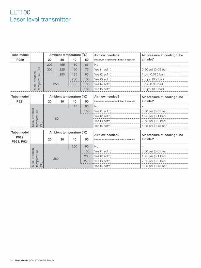
54 User Guide | OI-LLT100-EN Rev. D
LLT100Laser level transmitter
Tube model Ambient temperature (°C) Air flow needed? (minimum recommended flow, if needed)
Air pressure at cooling tube air inlet*P920 20 30 40 50
Max
. p
roce
ss
tem
per
atur
e (°
C)
205 155 110 65 No –
300 225 150 75 Yes (1 scfm) 0.50 psi (0.05 bar)
280 185 85 Yes (2 scfm) 1 psi (0.075 bar)
350
230 105 Yes (3 scfm) 2.5 psi (0.2 bar)
305 130 Yes (4 scfm) 5 psi (0.35 bar)
165 Yes (5 scfm) 8.5 psi (0.6 bar)
Tube model Ambient temperature (°C) Air flow needed? (minimum recommended flow, if needed)
Air pressure at cooling tube air inlet*P921 20 30 40 50
Max
. p
roce
ss
tem
per
atur
e (°
C)
175 85 No –
150 Yes (1 scfm) 0.50 psi (0.05 bar)
180Yes (2 scfm) 1.25 psi (0.1 bar)
Yes (3 scfm) 2.75 psi (0.2 bar)
Yes (4 scfm) 6.25 psi (0.45 bar)
Tube model Ambient temperature (°C)Air flow needed? (minimum recommended flow, if needed)
Air pressure at cooling tube air inlet*P922,
P923, P92420 30 40 50
Max
. p
roce
ss
tem
per
atur
e.
(°C
)
200 90 No –
155 Yes (1 scfm) 0.50 psi (0.05 bar)
280200 Yes (2 scfm) 1.25 psi (0.1 bar)
270 Yes (3 scfm) 2.75 psi (0.2 bar)
Yes (4 scfm) 6.25 psi (0.45 bar)

OI-LLT100-EN Rev. D | User Guide 55
Purge ring
The purge ring is an important accessory when used in conjunction with the dust tube. When installed, it allows air to be pushed in between the instrument lens and the dust tube, thus pushing all forms of dust away from the lens and acting as an additional barrier against dust.
Figure 43 Purge ring
Figure 44 Dust tube and purge ring
Purge ring
Dust tube
External commissioning laser device
If too many obstacles are present around the beam path, the external commissioning laser device can help you align the LLT100. For more information, see section 11.7.1 on page 35.
Figure 41 External commissioning laser device
Laser
Dust tube
In applications where dust may be present (even in very small quantities), the dust tube accessory is highly recommended.
Figure 42 Dust tube

56 User Guide | OI-LLT100-EN Rev. D
LLT100Laser level transmitter
Adjustable pivot bracket
The adjustable pivot bracket simplifies installation of the LLT100 at an angle.
Figure 45 Adjustable pivot bracket
Figure 46 LLT100 on adjustable pivot bracket
Figure 47 Typical LLT100 installation in dusty environments

OI-LLT100-EN Rev. D | User Guide 57
Swivel mount
The swivel mount allows rotation of the LLT100 around the laser axis.
Figure 48 Swivel mount parts (left) and completed assembly (right)
Processflange
Swivel mount
assembly

58 User Guide | OI-LLT100-EN Rev. D
LLT100Laser level transmitter
Specifications
Dust tube
Base plate diameter 165 mm (6.5 in.) mounts on LLT100 standard flange
Length 257 mm (10.1 in.)
Material Epoxy powder-coated stainless steel
Gasket material Black compressible Buna-N rubber durometer rating shore 60A
Function Static air space prevents dust buildup, can be purged.
Offset from hot process interface to allow convection cooling, can be purged.
Purge
Purge air flow Must be oil free dry air
recommended flow between 0.5 and 4 l/minute
maximum inlet pressure 5.5 bar (80 psi)
Purge fitting 1∕8 NPT
Flange reducer
Side A 2 in. ANSI class 150 raised face flange DN50 PN40 raised face flange
Side B raised face 3 in. ANSI
class 150
4 in. ANSI
class 150
6 in. ANSI
class 150
DN80 PN40 DN100 PN40 DN150 PN40
Side B flat face 3 in. ANSI
class 150
4 in. ANSI
class 150
6 in. ANSI
class 150
DN80 PN40 DN100 PN40 DN150 PN40
Material 304 Stainless steel
Adjustable swivel mount
Outer diameter 210 mm (8.3 in.)
Mounting bolt pattern 3 bolt holes, 10 mm (0.4 in.) diameter
Tilt angle for aiming Continuously adjustable from 0° to 6°
Material Aluminum
Adjustable pivot bracket
Overall dimensions 185 mm (7.3 in.) × 249 mm (9.8 in.) × 55 mm (2.2 in.)
Opening diameter 60 mm (2.4 in.)
Mounting plate thickness 5 mm (0.2 in.)
Mounting bolt 4 × HHCS 5/8-11 × 2 SS, + 8 × Washers + 2 × lock washers + 4 × nuts, bolt hole 8 × 18 mm (0.7 in.)
Reflector
Function Reflective panel for positioning applications up to 200 m
Size 90 cm × 90 cm (36 in. × 36 in.)
Material Aluminum with reflective paint
Cable glands and stopping plugs
Description Ex cable glands with ½ in. NPT or M20 thread size
Ex C1/D1 cable glands with ½ in. NPT or M20 thread size
Demo kit
Description Rugged carrying case with LLT100, dust tube, battery pack, laser pointer tool
External laser pointer tool
Function Laser pointer accessory used for targeting and aiming purpose.
Pointing laser 650 nm wavelength
Less than 1 mW output power
Pointing laser safety Class 2M

OI-LLT100-EN Rev. D | User Guide 59
Appendix C Instrument specifications
Measurement
Range for liquids:
for solids:
for positioning:
0.5–30 m (2–100 ft)
0.5–100 m (2–330 ft)
0.5–200 m (2–660 ft)
Resolution 5 mm (0.2 in.)
Typical accuracy ±11 mm (0.4 in.)
Measuring beam Laser wave length: 905 nm, eye safe, Class 1
Laser beam divergence < 0.3°
Output
Analog 4 – 20 mA, NAMUR compliant
Digital HART 7 (multi-variable output)
Communication Local LCD, EDD/DTM, handheld
Power supply
Powered from the loop 4 – 20 mA, 15.5 – 42 VDC (If using HART, minimum input voltage is 21 VDC)
Heated lens option 24 VDC (3 W)
Mechanical
Enclosure material Powder coated aluminum (standard), 316L stainless steel (option)
Dimensions (W × H × D) Universal – flat flange 247 mm × 215 mm × 165 mm (9.7 in. × 8.5 in. × 6.5 in.)
Class 150 – raised flange 240 mm × 242 mm × 154 mm (9.5 in. × 9.5 in. × 6.1 in.)
Class 300 – raised flange 247 mm × 242 mm × 165 mm (9.7 in. × 9.5 in. × 6.5 in.)
DIN PN 16 – raised flange 247 mm × 242 mm × 165 mm (9.7 in. × 9.5 in. × 6.5 in.)
DIN PN 40 – raised flange 247 mm × 242 mm × 165 mm (9.7 in. × 9.5 in. × 6.5 in.)
Hygienic flange 223 mm × 237 mm × 137 mm (8.8 in. × 9.3 in. × 5.4 in.)
Weight of standard model Aluminum enclosure with universal aluminum flange: 3.7 kg (8.2 lb)
316L stainless steel enclosure with universal stainless steel flange: 8.6 kg (19.0 lb)
Weight of pressure rated model Aluminum enclosure: 6.7 – 7.2 kg (14.8 – 15.9 lb) depending on flange
316L stainless steel enclosure: 10.0 – 10.5 kg (22.1 – 23.2 lb) depending on flange
Weight of hygienic model Aluminum enclosure: 5.8 kg (12.8 lb)
316L stainless steel enclosure: 9.1 kg (20.1 lb)
Protection class IP66/IP67/Type 4X
Process fitting Flange (ASME 2 in., DN50), hygienic fitting/tri-clover 4 in. (ISO2852)
Wetted parts Aluminum Universal Flange: aluminum, borosilicate window, silicone o-ring
316L SST Universal Flange: 316L SST, borosilicate window, silicone o-ring
Hygienic Flange: 316 SST, borosilicate window, silicone 3A CL2 o-ring
High Pressure Flange: DUPLEX 2205 SST (EN 1.4462), fused borosilicate window
Operation
Display Integrated 128 × 64 pixels LCD with Through-The-Glass (TTG) interface
Software features Volume computation, damping, filtering, thresholds/alarms, user-configured display (with LCD)

60 User Guide | OI-LLT100-EN Rev. D
LLT100Laser level transmitter
Laser
Measuring laser 905 nm near infrared pulsed semiconductor laser
7.1 µW average power output
45 W peak power output
Measuring laser life expectancy 25 years typical MTBF
Measuring laser safety Always on IEC60825-1 Ed. 2, 2007
Class 1 laser safe for all conditions of use.
Optical
Total optical aperture 50 mm (2 in.)
Standard window material Tempered borosilicate cemented glass
Pressure rated window material Borosilicate fused glass
Lens impact resistance Impact tested at 4 joules
Beam divergence Δ < 0.3°
Beam spot width Distance 1 m
(3 ft)
3 m
(10 ft)
5 m
(16 ft)
10 m
(33 ft)
20 m
(66 ft)
30 m
(98 ft)
50 m
(164 ft)
100 m
(328 ft)
150 m
(492 ft)
Approx. spot width
0.7 cm
(0.3 in.)
2.0 cm
(0.8 in.)
3.3 cm
(1.3 in.)
6.6 cm
(2.6 in.)
13.5 cm
(5.3 in.)
20 cm
(7.9 in.)
34 cm
(13.4 in.)
69 cm
(27.2 in.)
108 cm
(42.5 in.)
Beam direction 90° ± 5° from mounting flange for measurements of liquids
Environmental conditions
Operating temperature –40 °C to +60 °C (–40 °F to +140 °F), up to 280 °C (535 °F) with cooling tube
Storage temperature –40 °C to +85 °C (–40 °F to +185 °F)
Survival temperature –40 °C to +80 °C (–40 °F to +175 °F)
Process pressure Base model:
Hygienic model:
Pressure-rated model:
–1 to +2 bar (29 psi – universal flange)
–1 to +1 bar (15 psi)
–1 to +49.6 bar (719 psi), depending on flange
Altitude Up to 2000 m
Relative humidity 0–100%
Electrical equipment Class III
Pollution degree 4 (IP66/IP67/Type 4X)
Overvoltage Category 1
Hazardous area considerations
Gas and dust rating This equipment can be used in flammable gases or vapor hazardous locations. See Appendix A “Hazardous Area Consideration & Labels”, on page 47 for complete details.

OI-LLT100-EN Rev. D | User Guide 61
Appendix D EU Declaration of ConformityFor the latest EU declaration of conformity version, please contact ABB.

This page intentionally left blank


OI-
LLT1
00
-EN
Rev
. D
07
.201
7
Contact Us
NoteWe reserve the right to make technical changes or modify the contents of this document without prior notice. With regard to purchase orders, the agreed particulars shall prevail. ABB does not accept any responsibility whatsoever for potential errors or possible lack of information in this document.
We reserve all rights in this document and in the subject matter and illustrations contained herein. Any reproduction, disclosure to third parties, or utilization of its contents—in whole or in parts—is forbidden without prior written consent from ABB.
© ABB, 2017AA012909-01
ABB Inc. Measurement & Analytics3400, rue Pierre-ArdouinQuébec (Québec) G1P 0B2CanadaPhone:North America: 1 800 858 3847Worldwide: +1 418 877 8111e-mail:[email protected]
www.abb.com/laserlevelwww.youtube.com/ABBMeasurementExpert