laser autogenous brazing of biocompatible, dissimilar ...yly1/pdfs3/namrc41-1592.pdf · laser...
TRANSCRIPT

Laser Autogenous Brazing of Biocompatible, Dissimilar Metals in Tubular Geometries
Gen Satoh, Grant B. Brandal, Y. Lawrence Yao Department of Mechanical Engineering
Columbia University New York, NY, USA
Syed Naveed
Boston Scientific Corporation Marlborough, MA, USA
ABSTRACT The successful joining of dissimilar metal tubes would enable the selective use of the unique properties exhibited by biocompatible materials such as stainless steel and shape memory materials such as NiTi, to locally tailor the properties of implantable medical devices. The lack of robust joining processes for the dissimilar metal pairs found within these devices, however, is an obstacle to their development and manufacture. Traditional joining methods suffer from weak joints due to the formation of brittle intermetallics or use filler materials that are unsuitable for use within the human body. This study investigates a new process, Laser Autogenous Brazing, that utilizes a thermal accumulation mechanism to form joints between dissimilar metals without filler materials. This process has been shown to produce robust joints between wire specimens but requires additional considerations when applied to tubular parts. The strength, composition, and microstructure of the resultant joints between NiTi and Stainless Steel are investigated and the effects of laser parameters on the thermal profile and joining mechanism are studied through experiments and numerical simulations. KEYWORDS Laser Welding, Joining, Brazing, NiTi, Shape Memory, Stainless Steel, Autogenous Laser Brazing INTRODUCTION
The joining of dissimilar metals is of great interest to the field of engineering due to the need for enhanced performance and decreased weight and cost in a wide range of parts and devices. These requirements drive the desire for the use of specific materials in selective and localized areas of a part. While straightforward applications of this concept have been realized and are enjoying great success in industry, these applications, such as tailor-welded blanks in the automotive industry, are generally concerned with joining similar types of metals such as high-strength steel to mild steel [1]. A greater degree of difficulty is encountered when joining materials with vastly different compositions and properties due to the greater possibility of the formation of brittle intermetallic phases as well as thermo-mechanical differences such as thermal expansion coefficients which lead to stresses within the dissimilar metal joint. These issues keep the majority of dissimilar metals from being joined by traditional joining methods.
In addition to the inherent issues faced by all dissimilar metal joining processes, joining features at the micro-scale introduces further difficulties largely due to the lack of precision in thermal input and joint morphology in macro-scale joining processes. Many processes rely on global temperature increases in a furnace [2] or the application of extreme forces during ultrasonic agitation [3][4]. These processes do not translate to many micro-scale applications which require significantly higher dimensional precision and require minimal and localized thermal input to protect heat-sensitive components. Requirements for joining dissimilar metals in the micro-scale are often encountered in the medical device industry where materials such as shape memory alloys (SMAs) and noble metals, in the form of Nickel-Titanium (NiTi) and Platinum, are used for their unique mechanical and thermo-mechanical properties, radiopacity, and biocompatibility. The geometry of many parts in implantable medical devices and instruments causes additional constraints on the joining process. The use of tubular geometries is governed by the need to pass fluids and or other devices through the lumen. Examples
Proceedings of NAMRI/SME, Vol. 41, 2013
include stents and catheters. The joining of tubes for these purposes, with their wall thicknesses being only hundreds of microns thick, requires even greater precision in the joining process.
A number of methods for joining dissimilar materials have been developed in order to overcome the formation of brittle intermetallics. The addition of an interlayer, which acts as a barrier between the two materials to be joined, is a popular option due to the relative ease of manufacture and availability of suitable filler materials, such as silver, that do not readily form intermetallics with typical base materials. However, the strength of the interlayer materials, as well as their biocompatibility are still major concerns. Filler materials are typically made of lower melting temperature materials, which limits the working temperature of the joined part and typically is correlated with lower strength. Diffusion bonding of dissimilar metal pairs with and without interlayers has been investigated by Ghosh et al. [5] and Kundu et al. [6] with some success but requires the application of a substantial stress to the items to be joined and heating of the entire part. Campbell et al. has shown the ability to form solid joints between dissimilar metal pairs with an interlayer through transient liquid-phase bonding where joining can occur at a constant temperature [7]. This method, however, relies on the existence of a melt-temperature depressant that can diffuse into the base materials upon heating, thus increasing the solidus temperature leading to solidification.
Localization of the thermal input for joining of micro-scale parts can be achieved by laser irradiation with its highly localized beam and precise thermal input. Vannod et al. have performed laser fusion welding of the NiTi-SS dissimilar metal pair [8]. While these joints have shown reasonable strength, as expected from fusion welding processes, the width of the joint is large, resulting in a widespread elimination of shape memory properties surrounding the joint. The authors have recently developed a new process, Autogenous Laser Brazing, for joining dissimilar metal pairs and showed the capability to join 381μm diameter NiTi and Stainless Steel wires in a butt joint geometry [9]. This process takes advantage of the thermal accumulation that occurs at the dissimilar metal interface prior to joining to produce a localized braze-like joint between the two materials. Joint widths have been shown to reach the micro-meter length scale using this process due to the localization of thermal accumulation at the dissimilar metal interface.
In this study, the Autogenous Laser Brazing process is adapted to the joining of NiTi and Stainless Steel in tubular geometries. The resultant structural and thermal constraints are expected to require significant modifications to the joining process. Laser joining experiments are performed and the resultant strength is determined through tensile testing while microstructural analysis is performed using optical microscopy (OM) and
scanning electron microscopy (SEM). Compositional information is provided by Energy-Dispersive X-ray Spectroscopy (EDS). Further understanding of the joining mechanism for tubular samples is gained through thermal and microstructural numerical simulations. BACKGROUND Laser Autogenous Brazing Process
In order to mitigate the formation of intermetallics in dissimilar metal joining, the authors have developed a new process, Autogenous Laser Brazing to form joints between dissimilar metal pairs without a filler material [9]. This process takes advantage of the imperfect thermal contact between the two faying surfaces before the joint is formed. A laser beam is used to precisely irradiate one side of the joint while scanning toward the interface. As the laser approaches the interface the reduction of conduction pathways from the beam spot causes a greater amount of thermal accumulation to occur, causing the temperature to rise. The softened or molten material then comes into intimate contact with the adjacent solid part, which is still relatively cool. This causes rapid quenching of the irradiated material and minimizes the amount of mixing between the two dissimilar materials.
Through-thickness joining at the interface requires that the temperature profile on the irradiated member’s faying surface be uniform. The thermal diffusivity of the material must be high enough such that there is not an appreciable difference in temperature between the top, irradiated, surface of the member and it’s interior. The strength of the temperature gradient formed in a sample under scanning laser irradiation can be described by the Fourier Number which is written as
𝐹 =𝛼𝐷𝑣𝑠��
(1)
where α=k/ρcp is the thermal diffusivity, D is the laser beam diameter, v is the scan speed, and so is the material thickness. Through-thickness thermal gradients are expected to form for cases where the Fourier number is much less than unity. This is caused by the interaction time with the laser being much shorter than the time required for thermal diffusion. The tubular geometry of the samples used in this study further increases temperature gradients compared to wires, due to the lack of a direct conduction pathway across the interior. Rotation of the tubular samples about their longitudinal axis, however, allows for direct irradiation around the entire circumference. Thus, so becomes the wall thickness rather than the tube diameter. This allows for higher scan speeds for the same Fourier number and minimal thermal gradients in the circumferential direction.
Proceedings of NAMRI/SME, Vol. 41, 2013

Since large-scale deformation during joining is undesirable due to the need to maintain part geometry, the temperature of the material should be kept below the melting temperature for the majority of the irradiated region. An axial force is provided to the parts to be joined during the Autogenous Laser Brazing process to promote wetting and quenching of the irradiated material on the adjacent, non-irradiated surface. Diffusion in Dissimilar Metal Pairs
In any joining process involving metals at elevated temperatures, diffusion is likely to occur, whether intended or not. In the case of joining similar materials, this diffusion is accepted and even encouraged in order to create a seamless joint. In the case of dissimilar metal joints where intermetallics are expected for form, however, the diffusion of materials across the interface must be minimized. As discussed above, one method to mitigate these effects is to eliminate the possibility of diffusion through the use of a diffusion barrier or interlayer coating. These layers are applied to one or both of the faying surfaces prior to joining and keep the base materials separated during and after joining. The other method, which is used during the Autogenous Laser Brazing process, is to restrict the maximum temperature achieved in the parts as well as the duration of heating to control the total diffusive transport across the interface.
The diffusive transport between two materials during a thermal cycle can be described as a diffusion couple. The two materials are initially separate with different, uniform compositions. Diffusion is allowed to occur across the interface with the diffusion coefficient following the Arrhenius relationship defined as 𝐷�� = 𝐷��� 𝑒𝑥𝑝�−𝑄�� 𝑅𝑇⁄ � (2) where Qef is the activation energy, R is the gas constant, T is temperature, and Def
o is the interdiffusion coefficient. The existence of intermetallics, which have a limited
homogeneity range, complicates diffusive transport in these material systems since the chemical potential at different compositions varies considerably. Even with a purely diffusion-based joining process, constant composition regions are expected to form at the intermetallic compositions [10]. The width of an intermetallic layer, Δx, formed during diffusion in a diffusion couple at a constant temperature can be estimated by the parabolic growth law [11] Δ𝑥 = 𝑘�𝑡� (3) where ko is the parabolic growth constant, t is time and n is nominally 0.5.
While diffusion has a large role in determining the resultant composition profile across a dissimilar metal joint, at higher temperatures caused by slower scanning and greater laser power, fluid flow may control the joint formation mechanism, final phases, and microstructure.
Numerical Simulation Thermal: A three-dimensional Fourier heat transfer
model is used in order to determine the thermal profiles in time and space existing within the tubes during the autogenous laser brazing process. The finite element mesh on the tubes consists of quadratic heat transfer elements with mesh density biased toward the joint interface. The laser irradiation is input as a heat flux on the outer surface of the tubes following a Gaussian spatial distribution which is translated in a helical pattern by applying a coordinate transformation to the nodes on the tube surface. The conductance across the interface between the two tubes is directed to change, irreversibly, from a low value indicative of two rough surfaces in contact, to the conductance of the NiTi base material, at the melting temperature of NiTi, 1583K.
Convective cooling of the material is included through the use of a heat transfer coefficient and a sink temperature of 300K. The heat transfer coefficient is determined through the use of the Zhukauskas relation for flow over a cylinder 𝑁𝑢����� = 𝐶𝑅𝑒��𝑃𝑟�(𝑃𝑟 𝑃𝑟�⁄ )� �⁄ (4) where m and C are constants dependent on the Reynolds number, Pr is the Prandtl number, n is a constant of 0.37 for Pr<=10, and Prs is the Prandtl number calculated at the surface temperature. The cross-flow velocity of Argon across the tubes is calculated using the flow rate and the cross-sectional area of the argon box. The effect of the tube spinning results in a surface velocity much smaller than that due to the Argon flow and is thus neglected. The convective heat transfer coefficient resultant from the Argon flow is thus calculated to be on the order of 600W/m2/K.
Grain Growth: The resultant grain size due to the thermal profile experienced by the material is predicted using a spatially resolved Monte Carlo grain growth simulation as described by the authors in a previous work [12]. In this case, the simulation is used to determine grain growth through solid-phase thermal treatment rather than epitaxial growth. Thus, a new scaling factor between the number of completed Monte Carlo Steps (MCS) and time must be determined. The scaling factor used in this study follows Raabe et al. [13] such that
∆𝑡���� =𝜆�
Δ𝑡��𝑚�𝑝𝑒������ (5)
where Δtreal is the time duration in seconds, λp is the width of a single element in the Monte Carlo model, ΔtMC is the number of Monte Carlo Steps, mo is the pre-exponential factor to the mobility, p is the driving force for grain boundary motion, Qgb is the activation energy for grain boundary mobility, kb is Boltzmann’s constant, and T is temperature. mo is calculated as
𝑚� =𝜈𝑏Ω𝑘�𝑇
(6)
Proceedings of NAMRI/SME, Vol. 41, 2013

where ν is the Debye frequency, b is the length of the Burgers vector, and Ω is the atomic volume. For Δtmc=1, Δtreal represents the time duration represented by a single MCS as a function of temperature. The spatial resolution of the Monte Carlo simulation used in this model is 1.33μm. Qgb is set to equal the activation energy of self-diffusion. Using this scaling factor, the total number of MCS required to simulate grain growth for a specific temperature time history can be calculated as
𝑀𝐶𝑆 = �𝑡Δ𝑡��𝑚�𝑝
𝜆�𝑒������� 𝑑𝑡
�
� (7)
For this study, since the grain growth is expected to occur in the solid state for the majority of the laser parameters, the energy for each node in the Monte Carlo model is based only on the number of interfaces as determined by the number of nearest-neighbors with a different crystal orientation. The effects of surface energy used in the previous work for epitaxial growth are removed for this analysis. Experimental Setup
NiTi and Stainless Steel 304 tubes with respective inner diameters of 940μm and 870μm and outer diameters of 1064μm were cut to two inch lengths for joining. The ends of the tubes were ground flat and perpendicular to the tube axis using 800-grit Silicon Carbide grinding paper. Ultrasonic cleaning was performed in an Acetone bath followed by drying by compressed air. The two dissimilar tube samples were aligned in a butt-joint configuration on a three-axis stage system consisting of an XY linear translation stage and a horizontal rotary axis. The tube to be irradiated was mounted in a chuck on the rotary stage and the second tube is aligned concentrically with the first and is held by bearings to allow for free rotation. Rotation is constant at a speed of 3600°/s. An axial force is applied to the non-driven tube through a weight to ensure consistent and repeatable force
Figure 1: Schematic diagram of laser processing setup for tube joining. Note helical laser scan path to promote temperature uniformity at the joint interface.
application. Inert gas shielding is provided by Argon flow into a box surrounding the joint at a flow rate of 10cfh. Irradiation of the tubes is performed with a Fiber laser with a maximum power output of 20W at the 1064nm YAG wavelength. Laser firing is synchronized with the stage motion allowing for consistent laser scan paths. Processing was performed using continuous-wave (CW) laser irradiation. A schematic diagram of the experimental setup and laser scan path are shown in Fig. 1. RESULTS AND DISCUSSION Joint Geometry
Figure 2 show an optical micrograph of a NiTi-Stainless Steel dissimilar metal joint as formed by the autogenous laser brazing process. Oxidation caused by the heating cycle is observed locally around the joint interfaces and is limited primarily to the NiTi-side of the joint. No evidence of melting or deformation of the Stainless Steel tube is observed on its outer surface. This indicates that the majority of the laser interaction and temperature rise was experienced by the irradiated tube as desired to minimize diffusion and/or other mass transport across the dissimilar metal interface. Some deformation of the geometry is induced, evidenced by the increase in the outer diameter of the NiTi tube adjacent to the joint. This deformation is more pronounced for samples irradiated under higher laser powers due to excessive softening/melting resulting in buckling and collapse of the original tubular geometry. At the lower power levels, no evidence of large-scale melting of the NiTi-side of the joint is observed. Samples irradiated at higher power levels do show evidence of melting in so much as they possess smooth outer surface morphologies where laser irradiation occurred with evidence of some fluid flow in the solidified geometry. Each helical laser scan can also be observed in the surface morphology.
Figure 3 shows EDS maps of samples irradiated at two different power levels after cross-sectioning and
Figure 2: Optical micrograph of typical joint produced between NiTi and Stainless Steel tubes through the Autogenous Laser Brazing process. Note discoloration on outer surface of NiTi tube due to oxidation.
Proceedings of NAMRI/SME, Vol. 41, 2013

Figure 3: EDS maps of tube wall after cross-sectioning on YZ-plane for laser powers of (a) 13W and (b) 15.2W. Note greater deformation for higher power processing. Red, green, and blue represent Fe, Ni, and Ti. polishing. It is observed that the thickness of the NiTi tube walls increases in the irradiated portion due to softening of the material during irradiation and the application of an axial force. The sample irradiated at lower power, Fig. 3a, shows a modest increase in thickness, allowing the thinner NiTi tube wall to nearly match the thickness of the SS tube wall at the interface. The sample irradiated at higher power, Fig. 3b, experiences excessive deformation and thickening of the tube wall at the joint resulting in a NiTi wall thickness greater than that of the SS. This has the effect of increasing the overall joining area for samples irradiated at higher powers and the resultant strength of the joints must be viewed in light of this increased surface area.
The cross-sections also indicate that joining was achieved across the majority of the thickness of the NiTi tube wall for both laser powers. The lumen of the tubes, which must remain clear after joining are also not significantly impinged upon by the displaced material.
Joint Composition
The EDS color maps in Fig. 3 also describe the
mixing between materials occurring during the joining process. In each figure, Fe, Ni, and Ti are represented by red, green, and blue coloring respectively. The NiTi sides of the joints are a uniform green/blue coloring and the SS
portion has red coloring. The interfaces between the two regions for the two laser power levels, however, are starkly different. At lower laser power, the interface is delineated by a sharp change in the composition. Some regions along the interface show some signs of greater mixing but the joint width is narrow relative to the tube wall thickness. At the higher power level shown in Fig. 3b, the region with mixed red/green/blue coloring is significantly wider and non-uniform with the narrowest region occurring at the midpoint of the wall thickness. The mixed region is also observed to extend past the original interface position, into the SS tube material. This suggests that, at the higher power levels, melting of the SS-side of the joint does occur. This is undesirable due to the added mixing occurring for such samples which is expected to result in the formation of a greater volume of brittle intermetallic phases. Figure 4a shows the atomic fractions of Fe, Ni, Ti, and Cr across the joint interface following the path depicted in Fig. 3a. The overall profile across the interface indicates a diffusion-dominated joining mechanism with its monotonic, sigmoid-shaped composition contour across the interface. Joints that are formed through a melt-dominated process between the same materials have shown the layer between the base
Figure 4: EDS line scans across joint interface for samples irradiated at (a) 13 and (b) 15.2W. Follows paths along center of tube wall depicted in Fig. 3a and 3b.
Proceedings of NAMRI/SME, Vol. 41, 2013

Figure 5: Joint width vs. laser power as measured from
EDS line scans. Line numbers correspond to those indicated in Figure 3a-b.
materials to be a nearly constant composition due to the strong mixing caused by Marangoni convection within the melt pool [9]. No evidence of such constant composition region is observed in these profiles.
Figure 4b shows a composition profile across a joint that was formed at a higher laser power of 15.2W. The profiles show a significantly wider mixed zone between the two base materials with large oscillations across its width. Some evidence of constant-composition regions within the mixed zone is observed, such as the region between 38μm and 42μm positions. This could be caused by two different mechanisms, either melting or long-term diffusion in the solid state. As described above, with intermetallic phases with narrow homogeneity ranges expected to form in a Ni-Ti-Fe mixture, diffusive mass transport across the interface will cause the formation of constant-composition regions within the mixed layer. The width of these regions is a function of the temperature profile in time as described in Eq. 3. For higher temperatures and longer processing times, the width of the intermetallic layer is expected to increase. The frequent and large oscillations in the composition profiles across the mixed zone, however, indicate that a mechanism beside diffusion, which would result in a monotonic change in composition across the interface, is responsible for the mixing at these higher laser powers. It is believed that the composition profiles are a result of a combination of diffusion and high-temperature deformation.
Figure 5 shows the width of the mixed zone observed at the interface as measured by EDS line profiles as a function of applied laser power. The overall width is seen to increase as a function of laser power except at the highest laser power. For the lowest power levels, no evidence of large-scale melting of the tube walls is observed in the microstructure. This suggests that the layers are formed in a diffusion-based mechanism. The thickness of the joint is also observed to be nearly
constant along the wall thickness of the tubes. This is expected since, for the parameters considered in this study, the Fourier number as calculated from Eq. 1 suggests that there will be a negligible temperature gradient across the wall thickness. The significant differences in joint thickness for the high-power irradiated samples is considered to be due to deformation of the softened, mixed material rather than inhomogeneous temperature profile across the wall thickness. Grain Growth
Figure 6a-c shows portions of the cross-sections (YZ-plane) of a sample joined by autogenous laser brazing different distances away from the joint interface after etching by Kroll’s reagent. As revealed by the etching, the overall grain size of the NiTi is observed to increase in the irradiated region due to the high temperatures experienced during processing. The base NiTi tube has a grain size of roughly 8μm which increases to a maximum of roughly 30μm close to the joint interface. The majority of the grain growth is confined to the irradiated region with some growth occurring to areas not directly affected by the laser. Figure 7 shows grain size as a function of distance from the joint interface for samples irradiated at two different laser powers. The two curves show that grain growth does extend past the laser start position to the un-irradiated material and that the grain size closer to the laser start point are quite similar for the two laser powers. More significant changes in grain size, however, are observed as the joint interface is approached. For lower laser powers, the grain size decreases at the interface while for the higher laser power the grain size continues to increase. This difference in
Figure 6: Optical micrographs of typical tube wall cross-section after mechanical polishing and chemical etching. Images taken (a) 2.5mm away, (b) 1.2mm away, and (c) at the dissimilar metal interface along the NiTi tube wall.
Proceedings of NAMRI/SME, Vol. 41, 2013

Figure 7: Average grain size as a function of distance from joint interface as measured though line-intersect method on samples joined at two separate laser powers. Note decrease in grain size at interface for lower power. distribution is considered to be caused by the difference in thermal energy stored in the materials. For low laser powers, the peak temperature will be lower along the entire irradiated path. This heat can be quickly dissipated once the joint is formed to the comparatively cool SS tube. For the higher power sample, overheating of the NiTi material occurs, resulting in slower quenching of the material upon contact with the SS.
The grain growth observed within the wall of the irradiated tubes also provides evidence as to the mechanism responsible for joining in this study. Following the laser along a path along the length of the tube toward the interface, the grain size increases in a monotonic fashion from a roughly the laser start point to a maximum some distance away from, or at the interface. No sudden jumps in grain size, to larger or smaller grains, are observed along the path and grain sizes tend to the base material’s grain size at the edge of the irradiated zone. These results suggest that little-to-no melting has occurred in these sections. If melting had occurred, the initial grain size of the base material would be erased, and due to the quick quenching provided by the localized thermal input of a laser beam and the minimal thermal mass of the tubing, a much finer grain size would be expected to form. Thus, initial evidence suggests that the Autogenous Laser Brazing process, when applied to samples with a tubular geometry, results in primarily a diffusion-based joining mechanism. This is in contrast to the authors’ previous work where it was found that for the joining of 381μm diameter NiTi and SS wires, the joining was caused by localized melting at the joint interface.
Joint Strength Figure 8 shows the strength of the joined samples measured in tension along the axis of the tubes for a range of applied laser powers, holding other parameters such as axial translation speed, laser spot overlap, axial force, and beam spot size constant. Due to differences in geometry for the samples irradiated at different laser powers, load at fracture values were normalized by the projected area of the fracture surface to determine the stress at fracture for each sample. The joint strength is observed to be the highest and the most consistent at the lower power levels of 12W and 13W. As laser power is further increased to 14W, a sharp drop in strength is observed which continues on to the samples irradiated at the 15W power level. Joint strength increases slightly for the samples joined at the 17.3W power level. While there seems to be little trend in the tensile strength results with power, these results can be better understood when they are considered in conjunction with the joint width and joint geometries discussed above. As observed in Fig. 3a and 3b, the geometry of the joint is not uniform between different laser parameters. While the overall tubular shape of the members is maintained, higher laser powers show greater deformation and bulging in the joined region. At the highest laser powers, this causes the irradiated NiTi tube material to encompass the adjacent SS tube wall, which significantly increases the joining area and changes the joining geometry such that some regions are under tension and some under shear loading. While any increases in the projected area can be accounted for in the strength, increases in joining area under shear loading, caused by joining faced being perpendicular to the loading direction, are not included in the area calculation. It is believed that this increased joining area caused by the displaced NiTi material coming into contact with the inner and outer surfaces of the SS tube are responsible for the increased strength for the samples irradiated at the 17.3W power level. The joints produced by the Autogenous Laser Brazing process at the lower power levels show good
Figure 8: Joint strength vs. laser power. Note sharp drop in joint strength at 14W.
Proceedings of NAMRI/SME, Vol. 41, 2013

Figure 9: Optical micrographs of fracture surface for sample processed at 13W laser power. Note joining across entire NiTi tube wall (Left) and a portion of the thicker SS tube wall (Right) as indicated by Tube and Joint Inner Diameters (I.D.) and Outer Diameters (O.D.). strength with some reaching over 500MPa in tension. In comparison, the base NiTi tube material undergoes a phase transformation between austenite and martensite at roughly 480MPa. This phase transformation, however, was not observed during tensile testing. Figure 9 shows the NiTi and SS fracture surfaces from a joint formed at the 13W power level. The areas that were joined before fracture can be identified by their brighter appearance and lack of oxidation-induced discoloration. The joining between the NiTi and SS tubes at low power was limited to a cross-section roughly the size of the NiTi tubes cross-section as shown by the greater joint inner diameter (I.D.) relative to the tube I.D. on the stainless side. At higher power levels, the joint was observed to encompass a much larger cross-sectional area than either the NiTi or SS tube cross-sections. This is enabled by the excessive deformation of the tubes during joining causing them to collapse and lose their shape. As shown in Fig. 10, which depicts the projected cross-sectional area after fracture as a function of laser power, the joint area for the samples irradiated at low powers is actually smaller than the original NiTi cross-section. This difference between the joint cross-section and the base material’s causes the stress in the NiTi to be lower than at the joint, causing the phase transformation not to occur. At the higher power levels, the joining area is greater than both the base materials, however, the overall strength is too low to cause the phase transformation to occur in the NiTi tube.
The overall trend of reduction of strength as a function of laser power can be explained through the microstructure and thickness of the mixed layer formed between the two base materials. As shown in Fig. 5, the width of the joint increases with power due to the greater temperature achieved and resultant greater mixing between the materials. While the thickness of the joint may seem inconsequential, the brittle nature of the intermetallic phases that can form in a NiTi-SS mixture cause it to be an important consideration. Since brittle fracture is the expected failure mechanism in such materials, the failure stress is a function of the fracture
Figure 10: Projected area of fracture surface as a function of laser power. Note small fracture area for low power irradiation and overmelting resulting in larger projected areas for high power irradiation. toughness and the initial crack size. As the dimensions of the mixed layer decrease, so does the maximum initial crack size which leads to a higher fracture strength. Wei, et al. have shown similar results for the tensile strength of Aluminum-Copper joints with intermetallic layer thickness [14].
Another goal of the Autogenous Laser Brazing process is to create microstructures within the joints that are less susceptible to brittle fracture. While Fig. 5 shows that the overall width of the joints increases with laser power, the microstructure within the mixed layer could be any combination of phases with different thicknesses. The authors have shown that joining between NiTi and SS with a melt-dominated process results in a near-homogenous composition across the mixed layer due to the strong mixing due to diffusive and convective mass transport. The composition profiles shown in Fig. 4, however, only show constant composition mixed layers to form at higher laser powers. At the low laser powers such as in Fig. 4a, the composition is seen to vary smoothly and monotonically from one base material to the other, indicative of a diffusion-dominated mechanism. Numerical Simulation
Thermal: With the narrow homogeneity ranges of the
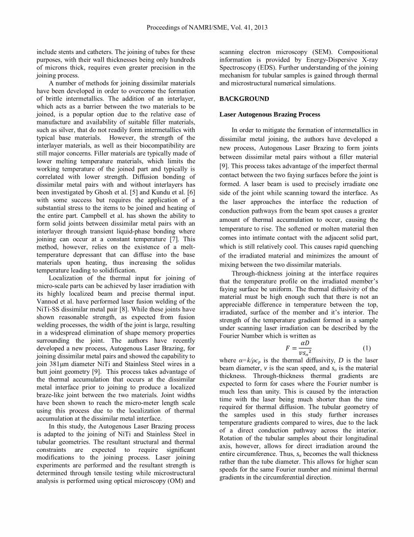
intermetallics phases expected to form in a Ni-Ti-Fe mixture, the formation of these phases is nearly guaranteed at elevated temperature and even short time durations. Equation 3 describes the width of the intermetallic layers as a function of the thermal profile in time, which can be determined through numerical simulation of the joining process. Figure 11 shows a temperature color contour map of the two tubes during irradiation from the numerical simulation. A sharp
Proceedings of NAMRI/SME, Vol. 41, 2013
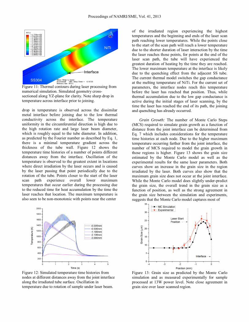
Figure 11: Thermal contours during laser processing from numerical simulation. Simulated geometry cross-sectioned along YZ-plane for clarity. Note sharp drop in temperature across interface prior to joining. drop in temperature is observed across the dissimilar metal interface before joining due to the low thermal conductivity across the interface. The temperature uniformity in the circumferential direction is high due to the high rotation rate and large laser beam diameter, which is roughly equal to the tube diameter. In addition, as predicted by the Fourier number as described by Eq. 1, there is a minimal temperature gradient across the thickness of the tube wall. Figure 12 shows the temperature time histories of a number of points different distances away from the interface. Oscillation of the temperature is observed to the greatest extent in locations where direct irradiation by the laser occurs and is caused by the laser passing that point periodically due to the rotation of the tube. Points closer to the start of the laser scan path experience overall lower maximum temperatures that occur earlier during the processing due to the reduced time for heat accumulation by the time the laser reaches that location. The maximum temperature is also seen to be non-monotonic with points near the center
Figure 12: Simulated temperature time histories from nodes at different distances away from the joint interface along the irradiated tube surface. Oscillation in temperature due to rotation of sample under laser beam.
of the irradiated region experiencing the highest temperatures and the beginning and ends of the laser scan path reaching lower temperatures. While the points close to the start of the scan path will reach a lower temperature due to the shorter duration of laser interaction by the time the laser reaches those points, for points at the end of the laser scan path, the tube will have experienced the greatest duration of heating by the time they are reached. The lower maximum temperature at the interface is likely due to the quenching effect from the adjacent SS tube. The current thermal model switches the gap conductance at the melting temperature of NiTi. For the current set of parameters, the interface nodes reach this temperature before the laser has reached that position. Thus, while thermal accumulation due to the low gap conductance is active during the initial stages of laser scanning, by the time the laser has reached the end of its path, the joining and quenching has already occurred.
Grain Growth: The number of Monte Carlo Steps (MCS) required to simulate grain growth as a function of distance from the joint interface can be determined from Eq. 7 which includes considerations for the temperature time histories at each node. Due to the higher maximum temperature occurring farther from the joint interface, the number of MCS required to model the grain growth in those regions is higher. Figure 13 shows the grain size estimated by the Monte Carlo model as well as the experimental results for the same laser parameters. Both curves show an increase in the grain size in the region irradiated by the laser. Both curves also show that the maximum grain size does not occur at the joint interface. While the Monte Carlo model does slightly under-predict the grain size, the overall trend in the grain size as a function of position, as well as the strong agreement in the grain size between the simulation and experiments, suggests that the Monte Carlo model captures most of
Figure 13: Grain size as predicted by the Monte Carlo simulation and as measured experimentally for sample processed at 13W power level. Note close agreement in grain size over laser scanned region.
Proceedings of NAMRI/SME, Vol. 41, 2013

the physical processes responsible for grain growth during the Autogenous Laser Brazing process. It is important to remember at this point, however, that the Monte Carlo model does not account for grain annihilation due to melting. In reality, if the material under irradiation were to experience the thermal profiles predicted by the thermal model, regions would encounter a number of melting cycles before final solidification. Regions that experience melting and resolidification would not be expected to have a microstructure with any resemblance to the base material due to the unique thermal profile caused by localized laser irradiation. Thus, it is expected that the thermal model may currently overestimate the temperature in the irradiated region and that, experimentally, the temperature does not get over the melting temperature for the majority of the laser scan path. CONCLUSION
The use of Autogenous Laser Brazing, a new process for joining dissimilar metals without filler materials, has been investigated for the joining of 1mm diameter NiTi and Stainless Steel tubes. Joint strengths achieved using this process reach 500MPa, approaching the phase transformation stress of the NiTi base material as well as the tensile strength of soft-temper stainless steel. Joints created through this process do not encroach on the lumen of the tubes, which is critical for the intended medical device applications. Line-scan EDS profiles show that joint widths are a strong function of applied laser power with the thinnest joints having a width of less than 10μm. Sequentially coupled finite element thermal and Monte Carlo grain growth simulations suggest that the joining mechanism for tubes is diffusion-based rather than the melt-dominated mechanism observed in a previous study by the authors on joining NiTi and Stainless Steel wires. ACKNOWLEDGEMENTS
The authors acknowledge financial support from NSF under GOALI Award CMMI -1130564. Use of characterization equipment in the Shared Materials Characterization Laboratory, Columbia University, is gratefully acknowledged. REFERENCES [1] Sun Z., Ion J. C. (1995) Review Laser welding of
dissimilar metal combinations, Journal of Materials Science, 30, pp. 4205–4214.
[2] Springer H., Kostka a., Payton E. J., Raabe D., Kaysser-Pyzalla a., Eggeler G. (2011) On the formation and growth of intermetallic phases during interdiffusion between low-carbon steel and
aluminum alloys, Acta Materialia, 59, pp. 1586–1600.
[3] Matsuoka S., Imai H. (2009) Direct welding of different metals used ultrasonic vibration, Journal of Materials Processing Technology, 209, pp. 954–960.
[4] Watanabe T., Sakuyama H., Yanagisawa A. (2009) Ultrasonic welding between mild steel sheet and Al–Mg alloy sheet, Journal of Materials Processing Technology, 209, pp. 5475–5480.
[5] Ghosh M., Chatterjee S. (2002) Characterization of transition joints of commercially pure titanium to 304 stainless steel, Materials Characterization, 48, pp. 393–399.
[6] Kundu S., Chatterjee S. (2008) Characterization of diffusion bonded joint between titanium and 304 stainless steel using a Ni interlayer, Materials Characterization, 59, pp. 631–637.
[7] Campbell C. E., Boettinger W. J. (2000) Transient liquid-phase bonding in the Ni-Al-B system, Metallurgical and Materials Transactions A, 31, pp. 2835–2847.
[8] Vannod J., Bornert M., Bidaux J.-E., Bataillard L., Karimi a., Drezet J.-M., Rappaz M., Hessler-Wyser a. (2011) Mechanical and microstructural integrity of nickel–titanium and stainless steel laser joined wires, Acta Materialia, 59, pp. 6538–6546.
[9] Satoh G., Yao Y. L. (2011) LASER AUTOGENOUS BRAZING - A NEW METHOD FOR JOINING DISSIMILAR METALS, Proceedings of the 30th International Congress on the Applications of Lasers and Electro-Optics, Lake Buena Vista, FL, pp. 315–324.
[10] Wagner C. (1969) The Evaluation of Data Obtained With Diffusion Couples of Binary Single-Phase and Multiphase Systems, Acta Metallurgica, 17, pp. 99–107.
[11] Bader S., Gust W., Hieber H. (1995) RAPID FORMATION OF INTERMETALLIC COMPOUNDS BY INTERDIFFUSION IN THE Cu-Sn AND Ni-Sn SYSTEMS, Acta Metallurgica et Materialia, 43, pp. 329–337.
[12] Satoh G., Huang X., Ramirez A. G., Lawrence Yao Y. (2012) Characterization and Prediction of Texture in Laser Annealed NiTi Shape Memory Thin Films, Journal of Manufacturing Science and Engineering, 134, p. 051006.
[13] Raabe D. (2000) Scaling Monte Carlo kinetics of the Potts model using rate theory, Acta Materialia, 48, pp. 1617–1628.
[14] Wei X., Yamaguchi T., Knishio K. (2011) Formation of Intermetallic Compounds on the Bond Interface of Aluminum-Clad Copper and its Influence on Bond Tensile Strength, Applied Mechanics and Materials, 117-119, pp. 984–989.
Proceedings of NAMRI/SME, Vol. 41, 2013