laser additive manufacturing - anuvidhya
TRANSCRIPT

Laser Additive ManufacturingTe ch n olog ica l Ch a l le n ge s & Op p ortu n i t ie s
HBNI Webinar
C P PaulHead, Laser Additive Manufacturing Lab
RRCAT, [email protected]

2
Acknowledgment
Current PhD Scholars

3
Presentation Plan
• Introduction
• Global & Indian Scenario
• LAM at RRCAT
• Technological Challenges
• New Opportunities
• Conclusions

Introduction to LAM
4

Laser Additive Manufacturing A B RI EF I NT RODUC TION
ISO/ASTM 52900 defines
Five criteria for a process to be called“Additive Manufacturing”
Add a footer 5
a) Process of joining of materials.
c) Layer-by-layer build up approach.
b) Starting from 3D model data.
d) Not subtractive manufacturing methodologies.
e) Not formative manufacturing methodologies.
When laser is used as a heat source, it is called LASER ADDITIVE
MANUFACTURING.

AM is not a new concept, it existed since long
Additive manufacturing is nature’s way of growth.
Man also learned it long back, but it is derived recently to manufacturing .
6

Comparison of AM with Conventional Processes
7
Description Additive Subtractive Formative
Methodology Addition of layer Removal of material Shaping of material
Volume Mass Customized or
Customized
Medium volume High volume
Lead time Less High Medium
Raw material Shapeless materials
(powder, wire, etc.)
Bulk material Molten Material/
Bulk Material
Buy to fly ratio Low High Medium
Surface Finish Low to Medium Medium to High Medium
Dimensional Accuracy Low to Medium High Medium
Material No limitations Limited by material
hardness
Metals and plastics
Size of components Limited to machine size in most
cases
Large components can
be machined
Large Components are
possible
Complex geometry Possible Limited Medium
Logistics Freedom Yes No No
Speed Can be relatively slow Fast Fast
Green Technology Reduced material wastage High material wastage Reduced Material
Wastage

Overall LAM Methodology
8
Ready to use
Machining
Post processing
Object + Imaging system
Designer+ 3D CAD S/W
Math data + Analysis
Slicing
Job manipulation
Mat’l deposition
CAD Model Making Laser Processing LAM Component

How does it help ?
9
Production
Application
Synthesis Analysis Doc. & dwg.
PlanningTool Proc. Raw Mat’l Proc.
CNC Program & mfg.
Design
QC Packing Usage
Conventional ManufacturingLaser Additive Manufacturing

Advantages of LAM
10
1. Complexity for Free
2. Simplification of Part Fixturing
3. Mass Customization
4. Integrated Components
5. Material Design Freedom
6. Logistic Freedom
7. Reduced Wastage

Classification of LAM
11
Laser Additive Manufacturing
Powder Bed Fusion
Laser Sintering
Laser Melting
Directed Energy Deposition
Powder Feeding
Wire Feeding

Classification of LAM
12
Directed Energy Deposition (LDED) Powder Bed Fusion (LPBF)
Functionally Graded Structures Multi-material Components Near Net Shaped Components Complex Geometry
Unlimited Complexity Refined Microstructure Light Weight Structures Thin Feature Fabrication
Laser energy selectively fuses regions of apowder bed to build 3D components
Focused laser energy is used to fuse materials bymelting as they are being deposited

13
Global Scenario
Template Editing Instructions and Feedback

14
Indian Scenario
Who is doing what ? • Industries are mainly using Plastic AM
Machines.
• Some leading academic institutions are joining
LAM R&D.
Who has metal LAMmachines ?
RRCAT, CMTI, ARCI, DMRL, GTRE, IITkgp, IITB, IITK,
IITPkd, CECRI, CGCRI, IGTR, CTTC, WIPRO,
Honeywell, 3D Incredible, Dentcare, GE, Objectify.
Who is in LAM Machine development ?
RRCAT, CMTI, CMERI, IITB, IITkgp, PSG
Coimbatore, Intech

LAM at RRCAT

LAM at RRCAT
In all of our research endeavors and collaborations, we strive tointegrate three key elements together to achieve newfundamental scientific insights, to produce groundbreakinghigh-impact results, and to create innovative LAM technologies.
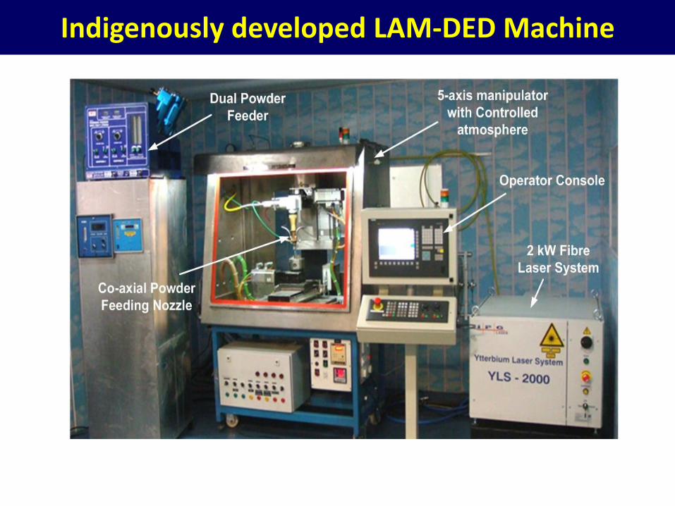
Indigenously developed LAM-DED Machine

18
SpecificationLaser : 2 kW Fiber laser
Job manipulation : 5-axis (Siemens 810D controller)
Working volume : 250 x 250 x 250 mm3
Powder feed rate : 2 – 20 g/min
No. of powder feeder : 2
Wire feeding (1 – 2 mm dia.) : 2 – 20 m/min
Purity in Glove box :< 20 ppm O2 & < 30 ppm H20
Advantages
a. High deposition rate
b. Dense and strong parts
c. Multi-material range
d. Larger parts
e. Easy material change
f. Reduced material waste
Limitations
a. Low dimensional accuracy
b. No self-supported structures
c. High thermal distortion

Indigenously developed LAM-PBF Machine

20
SpecificationLaser : 500 W
Beam manipulation : Scanlab Galvanoscanner
Beam Diameter : 500 microns
Scan Speed : 0.02 – 10 m/s
Working volume : 250 x 250 x 250 mm3
Layer thickness : 25 – 250 microns
Advantages
a. Shape complexity
b. Thin features
c. Higher mechanical strength
d. Dimensional accuracy &
Surface Roughness
a. Powder Reusability
Limitations
a. Limited multi-material capability
b. Porosity
c. Low build rate
d. Build Volume

21
Comparison of LAM Technologies
Feature DED PBF
Feedstock Powder/ Wire Powder
Part Repair Yes No
Laser Power >1kW 200W - 1kW
New Parts Yes Yes
Multi-Material Yes No
Surface Finish Medium-Poor Medium-Rough
Complexity Limited Maximum

LAM at RRCATProcess Development

Our Collaborators
23Many More…… List is appending fast…
Academic Institutes
National Laboratories

Deloro-50 Bushes
24
Fabrication Time: 45 days Fabrication Time: 72 Hours
Collaborators : Dr. C Sudha & Team, PMD, IGCAR

Mesh Type Spacers
25
Collaborators : Mr. S K Sinha & Team, RED, BARC
Mesh Type Spacers for Fuel Cluster Simulator of 540 MWe PHWR FuelBundle were successfully developed. These spacers are used to maintain thespacing among the fuel rods in Fuel Rod Cluster Simulator (FRCS) - a testfacility at BARC for experimental investigation of thermal hydraulicbehaviour of reactor fuel elements.

Mesh Type Spacers
26
LAM built Honeycomb Shaped Orifice
Honeycomb geometry orifices, made of SS304LN/SS304L, are installed at inlet of
Prototype Fast Breeder Reactor (PFBR) sub-assemblies as pressure drop devices
facilitating uniform temperature distribution and flow of liquid sodium.
A number of techniques, including
GTAW, conventional casting, investment
casting, etc. have been attempted. A
limited success is achieved in
investment casting. However, further
improvement is required
It is proposed to develop LAM process for
the fabrication of these orifices for better
dimensional control and surface finish.
Collaborators : CWD, IGCAR

Compact Heat Exchanger
27
Collaborators : I V Dulera, HTRS, BARC
Compact Heatexchangers are robust heatexchangers that combine
Compactness,
Low pressure drop,
High effectiveness, and
Ability to operate with a large pressuredifferential between hot and cold sides.
Fabrication feasibility of CHE by LAM is initiated.
It has potential applications in Supercritical CO2 Brayton cycles forSolar-thermal energy generation and Gen-IV nuclear reactors.
CHE by LAMSize: 200 mm x 200 mm x 150 mm
As per the inputs received from BARC, LAM of Compact Heat Exchanger (CHE) is initiated.

SiC Clad Layers on Zircaloy Tubes
28
Collaborators : Mr. S K Sinha, RED, BARC
Under accidental conditions, the local environment changes from normal operatingconditions and it yields in degradation of clad material (Zircaloy-4 (Zr-4) tubes) due tohigh-temperature oxidation and hydrogenation. It was targeted to develop LAM processfor deposition of 0.2 mm thick SiC clad layers on Φ10 mm x 0.6 mm thick x 100 mm lengthZircaloy-4 tube.
Deposition of SiC layers issuccessfully demonstrated.
Six such tubes are delivered toBARC for further examination.
With Ar gas at ID
Effect of Ar flow
EDS-Elemental Mapping SiC Deposited Zircaloy Tubes
Zircaloy-4 tube & its cross-section (typical)

Processing and Characterization of Materials using LDED
29
OUTPUT AS PUBLICATIONS
K Benarji, Y Ravi Kumar, A N Jinoop, C P Paul, K S Bindra (2020) Metals and Materials International. DOI: 10.1007/s12540-020-00838-y
K Benarji, Y Ravi Kumar, C P Paul, A N Jinoop, K S Bindra (2020Proceedings of the Institution of Mechanical Engineers,
Part L: Journal of Materials: Design and Applications 234, pp. 452-466.
Copper (In-house Requirement)
OUTPUT AS PUBLICATIONS
S Yadav, C P Paul, A N Jinoop, A K Rai, K S Bindra (2020)
Journal of Manufacturing Processes 58, 984-997.
Stainless Steel 316 and its composites (Collaborator: NIT Warangal)

Functionally Graded Materials using LDEDCollaborator: IIT Kanpur & Institute of Plasma Research
OUTPUT AS PUBLICATIONS
S Yadav, A N Jinoop, N Sinha, C P Paul, K S Bindra (2020) Int. J. Adv. Manuf. Technol. 108, 3779–3791.
Delero-50 and Stainless Steel FGMCollaborator: IGCAR

Graded Porous Structures

Specially Designed Components
Gear with Honeycomb Core Spacers
Prototype Hip Implant Impeller

Technological Challenges
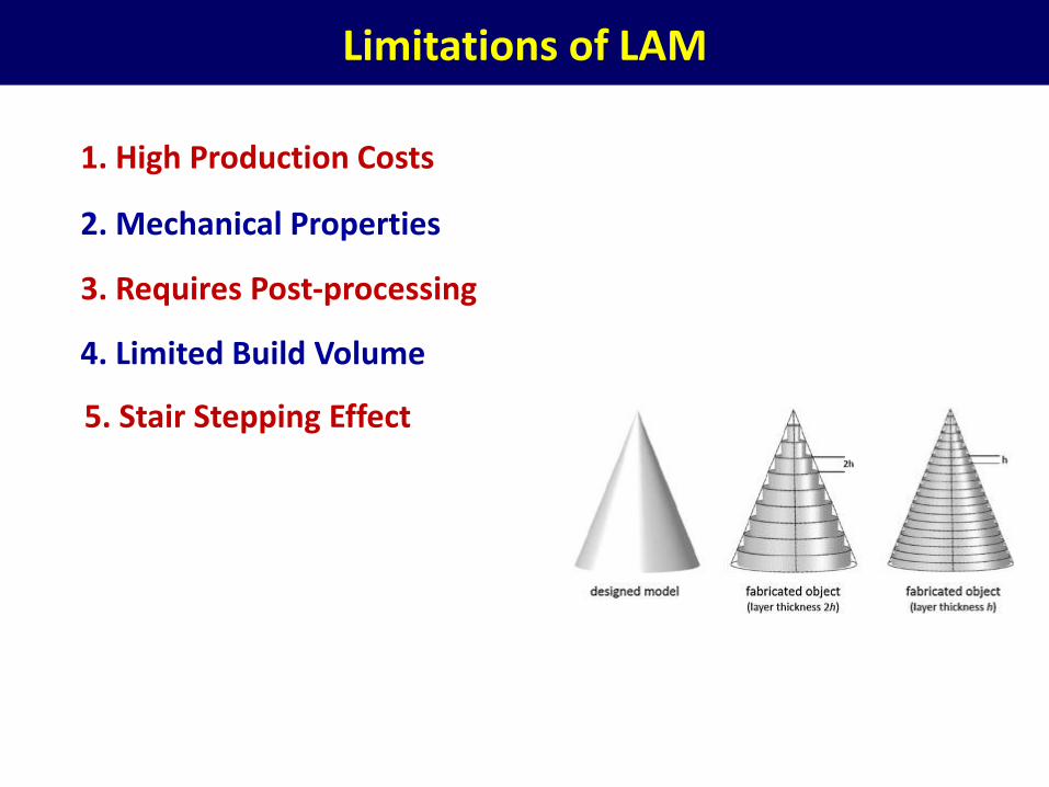
Limitations of LAM
1. High Production Costs
2. Mechanical Properties
3. Requires Post-processing
4. Limited Build Volume
5. Stair Stepping Effect

35
Opportunities in LAM
Machine/ Software Development
Process Development &
Control
Material/ Feedstock
Development
Design for LAMModeling & Simulation
Characterization & Testing
Quality Controls & Assurance
Application Development
Education & Training
All themes are important and we all need to work together to exploit its full potential

Summary
37
Summary
• LAM is a novel methodology capable of providingnew manufacturing solutions
• There is decent lead at international level, India isgearing for the adaptation.
• RRCAT has taken a lead role from machinedevelopment to process modeling.
• Collaboration with other national labs & academicinstitutes are playing key role.
• Innovation required is not limited to processdevelopment & material characterization.
• There is a need to tackle all 9 domains forsuccessful deployment of technology.

Thank You
+91-731-248 8396
+91-94256-66596
https://www.rrcat.gov.in/technology/laser/lmpd/laml/index.html
https://sites.google.com/site/drcppaul03/