large space structures fielding plan - apps.dtic.mil · the contents of this report are not to be...
TRANSCRIPT

USACERL TECHNICAL REPORT M-91/14' "'January 1991
US Army Corpsof EngineersConstruction EngineeringResearch Laboratory
AD-A232 097
Large Space Structures Fielding Plan
byCharles C. LozarAlvin SmithAndre N. Brackens
As the U.S. space program advances, there will be aneed for large space structures (LSS) to support differentmissions. The construction of extraterrestrial LSS,whether in orbit or on the surface of another body,requires the preparation and execution of exquisitelydetailed plans. Requirements for the LSS--the highdegree of reliability, the interface with other nodes of theoverall operation, and effective contingency plans-allpoint to the many integration activities that must occurbefore and during construction.
This study develops the preliminary plan for identifyingefforts that will be required for LSS construction tosupport future Army initiatives in space. It provides alogical sequence of steps that can be followed whetherthe LSS is to be a platform (unmanned) or a station(manned). To develop this plan, some documents fromthe National Aeronautics and Space Administration(NASA) were consulted; however, it should be noted that,in many areas, no reference documents exist.The complexity of this fielding plan suggested that an ELECTautomated version would make it easier to implement. FEB26 I9 m
Such a computer-based program should consist of a SN,hierarchical, multiple-track format and should be designedto serve developers at the top level (overall managementscheme) to lower levels (detailed, engineer usableinformation).
Approved for public release; distribution is unlimited.
91 2 2 n04c'

The contents of this report are not to be ued for advertising, publication,or promotional purpos"3. Citation of trade names does not constitute anofficial indorsement or approval of the use of such commercial products.The findings of this report are not to be construed as an official Depart-ment of the Army position, unless so designated by other authorizeddocuments.
DESTROY TIllS REPORT WHEN IT IS NO LONGER NEEDED
DO NOT RETURN IT TO TIlE ORIGLVATOR

USER EVALUATION OF REPORT
REFERENCE: USACERL Technical Report M-91/14, Large Space Structures Fielding Plan
Please take a few minutes to answer the questions below, tear out this sheet, and return it to USACERL.As user of this report, your customer comments will provide USACERL with information essential forimproving future reports.
1. Does this report satisfy a need? (Comment on purpose, related project, or other area of interest forwhich report will be used.)
2. How, specifically, is the report being used? (Infermation source, design data or procedure,management procedure, source of ideas, etc.)
3. Has the information in this report led to any quantitative savings as far as manhours/contract dollarssaved, operating costs avoided, efficiencies achieved, etc.? If so, please elaborate.
4. What is your evaluation of this report in the following areas?
a. Presentation:
b. Completeness:
c. Easy to Understand:
d. Easy to Implement:
e. Adequate Reference Material:
f. Relates to Area of Interest:
g. Did the report meet your expectations?
i,
h. Does the report raise unanswered questions?
i. General Comments. (Indicate what you think should be changed to make this report and futurereports of this type more responsive to your needs, more usable, improve readability, etc.)
5. If you would like to be contacted by the personnel who prepared tis report to raise specific questions
or discuss the topic, please fill in the following information.
Name:
Telephone Number:
Organization Address:
6. Please mail the completed form to:
Department of the ArmyCONSTRUCTION ENGINEERING RESEARCH LABORATORYATTN: CECER-IMTP.O. Box 4005Champaign, IL 61824-4005

REPORT DOCUMENTATION PAGE Form ApprovedOMB No. 0704-0188
Pubic om tkig burden tor thlo o ietair d lnn in m etirteed to werage I hour Pe ruspans. inotuding the tirs Ior reviewing intruction. eewdfn esltkg dat oauree.geheing e" nsd ,tnhi the die neded. and -ac ntig and revwing the edleltion d inlonrnr . Send co unte regarding t"le burden eetinme or eny ohm aped of this
ion ci lonn. Inciding e ug eilSo for tedudag this burden, o WaMWgtn Headqueters Servioe. Direaorge for ktfornialan Opene end Repo rt, 1216 5.1leueonOwits b6I;eey. Sufe 1204. Aakqton. VA 22?02.4302. el to the of1wci Manegement and Budget. Papenvoik Reduion PcIW (0704-01.), Weeg. DC .
1. AGENCY USE ONLY (Lemve Blnk) 2. REPORT DATE 3.REPORT TYPE AND DATES COVEREDI January 1991 Final
4. TITLE AND SUBTITLE 5. FUNDING NUMBERS
Large Space Structrures Fielding Plan PE 4AI62731
6. AUTHOR(S) PR AT41TA E
Charles C. Lozar, Alvin Smith, and Andre N. Brackens TU 056
7. PERFORMING ORGANIZATION NAME(S) AND ADDRESS(ES) s. PERFORMING ORGANIZATIONREPORT NUMBER
U.S. Army Construction Engineering Research Laboratory (USACERL) TR M-91/14PO Box 4005Champaign, IL 61824-4005
9. SPONSORINGIMONITORING AGENCY NAME(S) AND ADDRESS(ES) 10. SPON S RINMONIrORIrNGAGENCY REPORT NUMBER
HQUSACEATTN: CERD-M20 Massachusetts Avenue, NW.Washington, DC 20314-1000
11. SUPPLEMENTARY NOTES
Copies are available from the National Technical Information Service, 5285 Port Royal Road,Springfield, VA 22161
12s. DISTRIBUTION/AVALABILITY STATEMENT '12b. DISTRIBUTION CODE
Approved for public release; distribution is unlimited.
13. ABSTRACT (Maximum 200 words)
As the U.S. space program advances, there will be a need for large space structures (LSS) to supprt differentmissions. The construction of extraterrestrial LSS, whether in orbit or on the surface of another body, requires thepreparation and execution of exquisitely detailed plans. Requirements for the LSS--the high degree of reliability, theinterface with other nodes of the overall operation, and effective contingency plans--all point? , the many integrationactivities that must occur before and during construction.
This study develops the preliminary plan for identifying efforts that will be required for LSS construction tosupport future Army initiatives in space. It provides a logical sequence of steps that can be followed whether the LSSis to be a platform (unmanned) or a station (manned). To develop this plan, some documents from the NationalAeronautics and Space Administration (NASA) were consulted; however, it should be noted that, in many areas, noreference documents exist.
The complexity of this fielding plan suggested that an automated version would make it easier to implement. Such
3 computer-based program should consist of a hierarchical, multiple-track format and should be designed to serve
developers at the top level (overall management scheme) to lower levels (detailed, engineer usable information).
14. SUBJECT TERMS 156 NUMBER OF PAGES54
large space structures 1 5. COE
17. SECURITY CLASSIFICATION 18. SECURITY CLASSIFICATION 10. SECURITY CLASSIFICATION 20. LIMITATION OF ABSTRACTOF REPORT OF THIS PAGE OF ABSTRACTUnclassified Unclas.qi fled Unclassified SAR
NSN 7.40-01-20- 5t d00 FaI = Me. 24MPeeee b' AWSWI SMg-i
INO

FOREWORD
This research was conducted by the U.S. Army Construction Engineering Research Laboratory(USACERL) for the Headquarters, U.S. Army Corps of Engineers (HQUSACE) under Project4A 162731 AT41, "Military Facilities Engineering Technology"; Technical Area E, "Echelons Above CorpsSupport"; Work Unit 056 "Construction Technologies and Methodologies for Space." The HQUSACEtechnical monitor was George Aitkens, CERD-M.
The initial work was performed by the USACERL Engineering and Materials Division (EM). Dr.Charles C. Lozar is president of Architects Equities, Champaign, IL, and participated in this study undercontract to USACERL. Follow-on studies were conductcl and the framework of an automated versionwas developed by Andre N. Brackens, USACERL research assistant from the University of Illinois,Urbana-Champaign. Dr. Paul A. Howdyshell is Acting Chief, USACERL-EM.
COL Everett R. Thomas is Commander and Director of USACERL, and Dr. L.R. Shaffer isTechnical Director.
2
9

CONTENTS
Page
SF 298 1FOREWORD 2
INTRODUCTION ............................................ 5Background 5Objective 5Approach 5Scope 6Mode of Technology Transfer 6
2 DESCRIPTION OF THE PLAN .................................. 7Overview 7LSS Mission Definition 7Functional Requirements 7Design Alternatives Evaluation 16Contractor Sequence for Systems Fabrication 17Quality Assurance Verification 17Acceptance Testing/Safety Analysis 18Launch Site Operations 19Orbital Construction 19Testing, Operations, and Maintenance 20
3 LSS FIELDING PLAN AUTOMATION ............................ 22Objectives of Automating the Plan 22Process Explanation 22Diagrammatic V, ork Breakdown Structure 23
4 CONCLUSIONS AND RECOMMENDATIONS ...................... 46
BIBLIOGRAPHY 46LIST OF TERMS AND ABBREVIATIONS 48APPENDIX: SPREADSHEET KEY 50DISTRIBUTION
&oessaltob PONTIS GRA&IDTIC TABUnannounced 3Justification
ByDistributlooAvailabillt'y Oeats
jAvatiL bifor
D I'3 i i i
LARGE SPACE STRUCTURES FIELDING PLAN
1 INTRODUCTION
Background
With the resurgence of the U.S. space shuttle program, the need for large space structures (LSS) tosupport increasingly complex missions is imminent. Recognizing the potential for LSS in both spaceexploration and national defense, the Department of Defense (DOD) is studying the most feasible approachto providing manned and unmanned facilities.
The U.S. Army Corps of Engineers (USACE) is responsible for construction within the Army andAir Force. As such, it constructs facilities to meet military requirements in all types of environments.However, the extraterrestrial environment is an entirely new frontier, with little known about the behaviorof structures and issues related to material/design. To gain support in this area, USACE has designatedthe U.S. Army Construction Engineering Research Laboratory (USACERL) as the center for coordinatingconstruction research. In 1987, a USACERL Technical Report was published to provide comprehensivebackground information on current technologies that could apply to LSS.' All work within DOD,USACE, and USACERL is being coordinated with other affected agencies such as the NationalAeronautics and Space Administration (NASA), Strategic Defense Command (SDC), Army MaterielCommand (AMC), and Army Training and Doctrine Command (TRADOC).
A critical part of development and deployment of LSS is to establish a fielding plan that will serveas a systematic procedure for conducting these efforts. Reviews of the literature and the criteria developedfor NASA reveal that, although LSS construction has been conceptualized by artists for variouspresentations, little organized work has been done to document the actual sequence of events that mustoccur to place an LSS into orbit around the Earth. Such a plan is required to give developers a "roadmap"for fielding unfamiliar structures in an untested environment.
Objective
The objective of this work was to develop a preliminary plan identifying the key steps and sequenceof activities for fielding an LSS. The ultimate goal of such a plan is to minimize risk and ensure cost-effectiveness of the LSS.
Approach
Because there is very little flight experience for LSS, literature describing an actual attempt or planto place such a structure into space is very limited. Therefore, much of the information for this fieldingplan was taken from other sources-in particular NASA documents, which define the sequence of design
C.C. Lozar and L. D. Stephenson, State-of-the-An Technoloeies for Construction in Space: A Review, Technical Report M-87/17/ADA188412 (U.S. Army Construction Engineering Research Laboratory [USACERLI, September 1987).
5

and fabrication steps that must be followed as the basis for any experiment in spacc. These steps aregeneric to the space industry, and to a great extent reflect the safety, quality assurance, and verificationplans that NASA has used on previous projccts.
The fielding plan was developed as a flowchart of activities. Each major step is summarized inChapter 2. The plan was designed as a very basic roadmap for LSS development. It is intended that theuser obtain whatever information is necessary to design the LSS and tailor a specific fielding plan withthe lift vehicle sponsor. Design considerations will include the carrier's capacity and requirements forground processing and mating of parts before launch. Since these parameters will vary for different typesof LSS and launch vehicles, the user should understand that the basic fielding plan will have to becontinuously redesigned to provide an acceptable version for the specific operation.
Scope
This preliminary fielding plan is intended to be as broad as possible in scope. It offers numerousconsiderations for conditions and situations that relate to manned, rather than unmanned, orbital spacecraft.Platforms, which are unmanned, will be much less complex and a fielding plan for platforms would besomewhat simplified from the plan developed here.
The data and estimations in the fielding plan represent the best available at present and may notapply to every mission. In addition, these steps are to serve as a baseline only, with a specific plan to bedeveloped for each LSS project.
Mode of Technology Transfer
The information in this report will impact the planning and execution of LSS construction on orbit.It will form the basis for construction CPM charts as well as the contents of Technical Data Packages forspecific large space structures.
6

2 DESCRIPTION OF THE PLAN
Overview
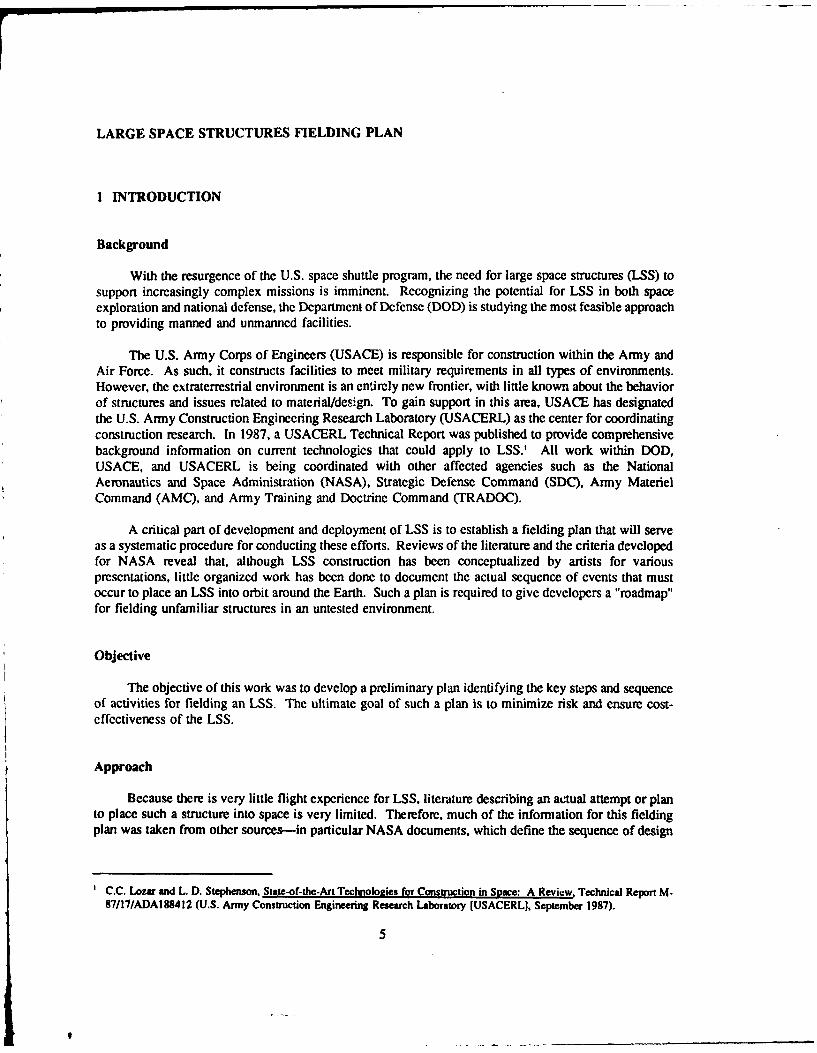
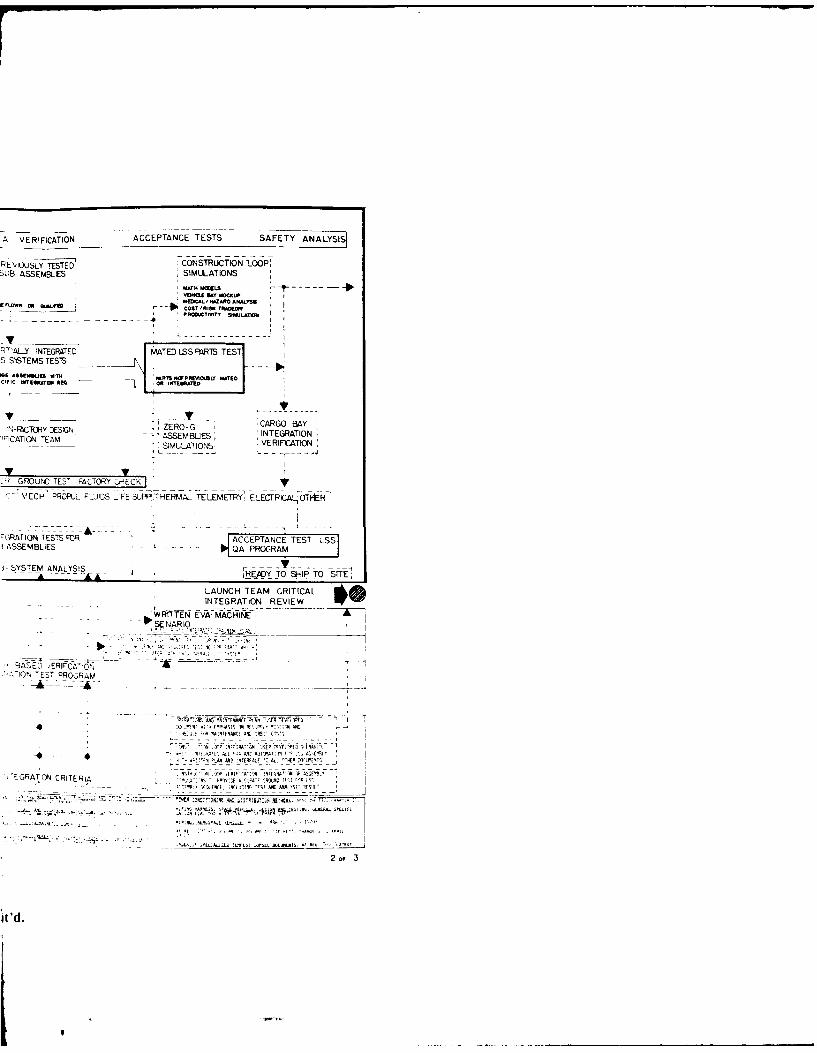
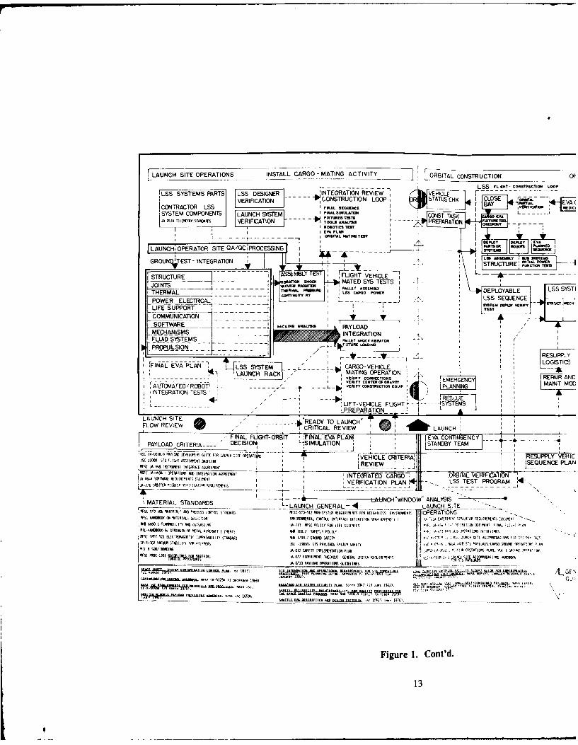
The LSS fielding plan is designed as a flow diagram (Figure 1), with the main activities shown inthe top line. Under these main activities are boxes containing many of the specific issues that must beaddressed. These boxes are interconnected by solid and dotted lines with arrows indicating the probableflow of action in one box to the next level or aspect to be considered. Below the specific issues are boxescontaining items such as secondary analyses, integration interfaces, and verification, quality assurance(QA), and quality control (QC) considerations. The two final lines reference existing NASA and DODdocuments.*
Each main activity is discussed in this chapter. It should be noted again that this fielding plan ispreliminary and will be augmented as more data and knowledge are gained.
LSS Mission Definition
General Approach
The mission definition component of the LSS fielding plan consists of items common to certaintypes of orbiting stations and platforms. The assumption is that the design will begin with a referencebaseline LSS system that exists as a schematic or concept description. The joints, struts, utility trays,radiators, rotary joints, and similar items form the main structural skeleton for the LSS, which is followedthroughout the diagram (i.e., by commonality of parts). The questions of pointing and control systemsfor the overall structural component, and the interface with other systems and subsystems become criticalfor determining which design parameters and variables would be most compatible with the objectives ofthe mission payload.
Functional Requirements
Purpose
The Functional Requirements section identifies both the managerial and engineering plans thatconsider the relationship between mission requirements and LSS components. At this stage, the feasibilityof fielding an LSS must be evaluated initially and the decision made on how to proceed. The items listedunder Mission Definition must be evaluated to determine the capability to fabricate and integrate the LSS,as well as the overall parameters and constraints for both the lift vehicle and orbit conditions.
Construction Loop
Under broad the category of Functional Requirements, a major component is the construction "loop"for LSS assembly. In this loop, decisions are made about the basis for procedures, extravehicular activity
The Bibliography is a comprehensive list of documents used in developing the fielding plan.
7

LA R GE S PA CE ST R UCT
1 LSS -MIS -SION DEFINITION FUNCTIONAL REQUIREMENTS-DSG LENTSEA
BASELINE REFER- GOTO PRELIMINARY LUC ~ .. ~~ TO EINAAj~U-n5TE!,4p N "A CONFIGURAINDSG A16
ENCE~~~ LS M PITIN !ANALYSIS PLAN AND *U~AgwoFOR MISSION OBJECTIVESSCHEMATIC OR YTMAN+IR EVA IORBIT -
CONCEPT LSS----------- TECHNIQUES DEFINED AUTOMATION ALTERNATE LSS LSS LS
DPMING EUREOS CAPA.BILITY D4ESIGNS
IACTiIE GRND CNTRL IgI N" Luna SS W e~T~MISSION AND MISSION CRI~ SUPPORT
JOINTS NODES - -- CONST SEQ I I DEFINITIONNEDPASIV I I PtW I I FOR LSS L-I
Sj IFIXTIUS - - 01
STRUTS TOMM LSS SUPPORTLS
UTILITY TRAYS .INIEFGH
RADIATORS FIE.A clc.
SYTM SYSTEMII IA4 NAY
I- - --Y CONTROL n.RISARARYFKTBIY EAT AEVA COST CT4DUTJR[S PREBUINAR
ANLYIS ~ ' 'I:VI2I~:~EV R EI LASK- FCUEV SIMUAO VIB[TINANTENNE rT-EINTERFACESC
NASAAS REF G ''..
CRITERIA
DATAEER [REQ LDISNGS ________AM TR ALS Y1 ILT _ _
PROULIO RE LMNR DESII JFCCLGN NLYI
EVA. PLAN 44Mk~NL , f 'I1S RERJI ms&. -_A INA j2 'A 3
NRAC CIEC EQUITIESA DESIGNTINft~INEFA
Figre1.LS felin pan9
QAQ I F'EIIAIN Q AKG

STRUJCTURE (LSS)
DO 1ALTERNATES EVAL RELIMIINARY ANALYSIS PHASE
FIG~~ONDESN AALYiS LAUNCH CRIT MR-ES%A CONFGR7:N DSG ANc" RUI
Ts FORMISSION OBJECTIVESAERATE 'LSS LSS' LS ORBITASEMTHNA
TN- AUCRNIsAL OE
DEVS1W ETOT SET IMILATIONY_ MECHA UISM &mor7 ,TSERMj j
NTCRCI Lm
INTEGRATdNKV7
fMISSK>N LSS F SANMN-floi wro- rj-*EIP SS L VES ONOHE
PRELMINARY ICRITERIA SET SNiuTT SYOTENS PROTOTYPEI1ST P-i L---~L - - MOCK-UPJ
-IST INTO S I
LR.S-~mE TEST FLY
S INITIAL TET LIFT VEHICLE IW I~S TAS- WORt.ACONEPT CARGO CRIEI RECYLU I ZERO-GTEST,
CNTA ITERA WAVE.--------1 -
I A AT~ I I o E ii~RI A -- T , E S . W A M A M E E S T 7 " - - - - 2 -I
1A DrT* mu -ENE --EWF '--N ,DESIGNED*ULIDAD POWER ARSI/T T
sT5TE.S BAY VARIABLES7CS AVAILABILITY
--- OONSTRIJCT7ON SEQU LYSIS ASOEKILTZ _E N, F 5_ V14RICE7O - I AIE rISLO - -
LT FUINS _FECLYCLEL ANALYI OL
-''5T Q1.LAL< -I ONTROL RISK OST SISOTIME- NARiAMiTES
2 I ANALrS PAFYCKAGE FO s- )twSTRUCTILN -
CRITICAL LSS S'STMS dlh- - DESIGN REVIEW
(SC - .' -' -' 'c EVA SQEENCE TOOL DES OK IxTURES NAN MACN,. COORS
*FeT PLAN NTCRATIU4_' ~DINTERFACES
VERIFICATION QA PACK<AGE AND-
ESIGN DEVELOPMENT -AN T- - ESTE S
- -1T OE.CLE
LJLPSMR E, A-SO ',(,RS . SECURITY
'I~~~~ or 3 ft F,
i Gielding plan.

FIELDING PLAN
CONTRACTOR_ SEQUENCE FOR LSS SYSTEMS FABRICATION AVERIFICATION ACCEPTANCEMTRLS EVALUATON 'MISSI, ,CP!'CULIAR, :CSTRUC-fl -, PREv'.4jSLY TESTED.
SEETION CRITERIA Si Cr,SEE ASSEMV, BLIES L--*: ANALYSIS 1; SUB ASSEMBLIES"ASS LI I EVA AND RO'OT11 :AT
SW .LA IuSC ETECOTROL PRFWNI am .MAF * CO!
SYSTEMS CRITERA 9 ,I ] r--LcCTRUCTURAL SYSTEM IUI
-- STRUM ROMI TRAY TElERS ,CHOd
. ECHANISMS CONT NTEA ES . " " - .TIALY NTEGRATED MATED LSS-. IOWTACTUATION "10 'N -________ _ LSS 5 5TEMS TESTS,
PROPULSION POWER PRESSUR ELM ......... TT"UTR AK CNRLVLE UPTURE TEST LAG ASSNSU W N o PMi
1. THSS~ MC OSUD. VACU UMTIETS - - SPECIFIC INTEGRATI MEG OR. IWItORAT
FLUID'SYSTEMS . .ECTICI1--..T' - RAS ISSSOR( EWFABRICATK)N OF SYSTEMS - - -
LIFE SUPPORT PRS.R QUALITY IAS.SURANCE I ZERO-,
ETTIROMMEST RECYCLE WASTE DURATION C EAI,- -A LS )N-C -, DESIGNASSEY,
' : s , p m N T-,T{O . VRIFI ATION TEAM li "ISM L________________NASA PERFORIIANCE IT-MATED PARISFCA SMLFLUIOS~CAIM EVLATO OO wa~l~ 4Ck .. •L
-'-JTHERMAL MGMT FUIS CME ETr EASE"RADITOR LWI E S O PLAIM 115 OTHIER MATERIAL_
[TELEMETRY DATA w'lu .. .TELEMETRY .DATA ws AtI -P. R 7IAJOR GRCuNO TEST FACTORY CHECK I
COMMUNICATICON TWMECPASS STORAGE ;SRLT _- ---___L • ........ ' NSTRU T.I ECH PROPUL FLUIDSILIFE SEITHEF
TER.V
EL iC ,.TM, SYSTE N TVEHICLE 'CARGO BAY LAUNCHI. "INTEGRATION FIXTURE DESIGNsoCRLT SLO__GL cro rl. CORTIU"TT LC J L_
pITYPE ASSEMBLY TEST E G f0-BOTS ' . -- - - INTEGRATION TESTS FOR
, TEST ASSEMBLY -L SAFETY ANALYSIS. SUBASSEMBLIES[ ROP TOAR -MACHINES LSS CARG
'DESIGN!SUB- SYSTEM ANALYSIS
LAUNCH TEAM PROGREVIEW AND ANALYSIS
A fANK TESTS WITH T - -R-TT
L S S P R O TO T Y PE S -.-- - - - - - - - -. PtRO B O TSTO O LS FIX T U R ES W... R I
- ~7~~EV8A~N EVA INTERFACES - -- - NARIC
'SHOCK CHARACTERISTI'S , - - - - - -
C^;RS .. S 1EIA T I REM N ... .I I - - T' .
'I~~~EARTI 'T , 'I ~ ~VERIFICATIONIT .......... . '. .. INTEGRATICN EST PROGIRAM
CARGO SAFETY
A.C T.CI -~ C ~ ~. _ - ~:LSS USES DEVELOPED- - I- -- -_______ICA.,LCTA AT. IC~ LTOA "> SPECIFIC ATTRIBUTE TEsS- - --
'' A T aI, - ''A i A'l ~"'a T 1A.Y O~ NASA DEVELOPED/ REQUESTED'
SPECIAL TEST REQUIREMENTS K~ ---- 4 - 4
~- ~ ~ 'NTEGRATION CRITERIAL - -_: MATERIALS CONTAMINATION . -,
TL -H ~ 1*.A.. 11 A 1
. 4 A..1 TT1TT
:~l. $ it1L T A.T ~TRAIV T . ' .. RA T:J~..lo, .~ EN'r'>. iL C. .T-
Figure I. Cont'd.
11
A VERIFICATION ACCEPTANCE TESTS SAFETY AAYI
REVIOUSLY TESTED CONSTRUCTION 1-OP:SUJB ASSEMBLES SIMULATONS
________COST 1ANWAR JRANALY
RTISJJy INTEGRATED M4ATED LSSPS TESTS S)STEMSTESIS \i
IC --TON~o Ov O ITERAE
',-F C7RY:ESGNZER-G CARGO BAY
~1CTI~ AMASSEMBUES; INTEGRATIONSIMULAT ONS VERIFCATION
ROUI\CTES- A T YECIK
MIECH PROPUL FPL JIDS .!FE SUPPT7HERMAL TELEMETRY. ELECTRICAL OTVER
IGRATION TESTS RPR ACCEPTANCE TEST LSSI-ASSEMBLIES C --- - A PROGRAM
3-SYSTEM A NALYSIS - - -R~ -O -I TO SIT 1
LAUNCH TEAM CRITICALINTEGRATION REVIEW
-~ WRITTEN1 EVA- MACHINI- ISENARIO
BASEC ERIFICAT10%~-A'ION TEST PROGRM
A111 MiPijlF -AW-t
* - 1' ":D kS ;, 'I0D rFT'I ,
VA ",F" q Nljf - N TSEN AN AIW - ll'NN
4 * CAC~ CNNA'ANOTN UNNA INENNC VA. i ,;FEN
- ~ ~ ~ ~ ~ ~ ~ ~ ~ ~ ~ ~ ~ ~ o 3GAC4CIEI 'A ~ENNC"C NTNSANCT
it' . - -N-VC C.AF -t~I~ A
LAUNCH SITE OPERATIONS INSTALL CARGO - MATING ACTIVITYOITLCSRUIO
L-LSS F.o cogw w LoLSS SYSTEMS PALRTS LSS DEIGNER ___ INTEGRATION REVIEW 7VEH L-----------------
VEIIAINCNTION ONLO TAt. CHK CLOSE r~ -
CONTRACTOR LSS cEUiE I ".JLBY ~ ~ VSYSTEM COMPONENTS LAUNCH SESTEM IC~TTS
VERIFICATION---------- A F- - - - PREPRATION JY-
IRON TICS TE
GROUNEST- INTEGRTIOM IN ASEMLY_2
-~~A S T S~ . .ISTRUCTUE IFLSTR CTUREL
'aL. ..
-
7THERMAL THE--- - MAL PRMS I S AG P-I DEPLOYABLE LSSYTPOWER ELECiTICAL __ - - - - - -- LSS SEQUNCE
TSTN~0WW [ Sh~TWl
- -- -- -~RACKING ANALSS PAYLOAD
T5 ITON
Ei FIA REA AN- LLSoSE CARGO-VEHICLE L'TC
141 C~ -A) 7-------- MATING OPERATION I-
r------ --- ---- I VERF RIFY CONNECTIONS EEGNY~I NA UF 4TED/ RbdT-------------- L VERIFY CONSThUIOMEQLAP 'PLANN ING IMAINT MOOINTEGRATION TESTS/
L -- LIFT-VE-ICLE FLIGHT
ALUNCH SITE AI 1'ED OL 7 gLOW REVIEW ~IED OLUNCH
CRITICAL REVIEW LUCFINAL FLIGHT-0 BT ~I 14AL-EVA PLAN: EW E Cy
PAYLOAD CRITERIA----' DECISION4 LISIMU..ATION STANDBY TA09 3 OSP5* DMOPEFll NA~5~ IVHICLE CJIER A, i -REMUPPLY VEHICI
FSC JA LAS INSTRUNEW IN TESRA LREVIENEW SEQUENCE PLANISFC JA-9 OPEUS ONG5JF AIAAS ASIEIM SPF1JI I N EA ED CRO C VRFCTION G VN IJA 464A SITWIS Rf),ARL!ANS DOCLFOC VERIFICATION PLAN LSS TEST PROGRAM454-76 ORSAIER IDDEC FIII5AT5I2 I ET
'MATERIAL STANDARDS ------in---- --- %UNC WINDOW' ANALYItS- -~ ~ S--LAUNCH GENERAL - 4 --- LAUNCH SITERSSD5%ATRA'AEPRCS DTRDLT STOASARn NfSSSSTDE-512 WAISYSOFI REUUIRF PFOS FOR WEIIIESS [WIIOWN7I OPERATIONS
AFSS WIAOR0 4ATJIALS SISE:TICA FFAVOMNAL CONTROL INTERFACE DEF141ION SPA, AFPf4D!L 11 2A !IOSF:1W S2'L72* EFQCIRD1lS _A1T*6 "0RE 1 FLFIL ITO AMD OJOSASSIAS, JA-713 RISC FOLICY FOR LIFE SCIE'R((S -1 SF JA 4 - I ' S:VION ORSC iS' I MEAL 1 - IRMIL -HA -Sc STRIKER OF ATAs AIRCRAF fIFIENTS 0I 100.7 WAETSO POLICLY * -/ , X$ A fT1 IS SWOI ]INS
AFSC SPEC 521 ELE rO NAA TI(T IC PA S SLrl STANDARD MR 1 0 ROUN D S A E TY ISOS 1 1 0 11 C I SIT E 111, 11C. 11 I LSP-A-NJ2 RVAL STABILIT OR JR I RS S 15830 STS PAYLOARE SYSTESETY 3C (A %AA IASB STS DAYLCODSICARGO SRORM 1PVFR! PR111L 5 SOL? CIE. JR-012 SAFETY 19LENEVIASO PLA PSOR 1, ,I -1 AR S'EATIOR FLAR, I-A I CP'5, TVIA* S
JA-S710 PAYLOAD OPEATIONS EUIDRI INES 1J_______~ 5'I~L U tIS 1 II5 IUAUM.ISMPRAI Imum -l I ULI~~k A.VJVLSAO~i~OLf~LSGI G'~ I.
SCALA AI~54~5
IJVR~q .l. Al . ,
SLIARQUI,.A- 11 16S56 lfl3.* Rqo t! T, ' I .01w ER. ______________
Figure 1. Cont'd.
13

BITAL CONSTRUCTION OPERATIONS MAINTENANCE TESTS
LSS FL.GNT- CONSTRUCTIOWN LOOP-E -1 1 . . . . . . . . . . . . . . ._, EA lBASEDtUs CHK ICLOSE forrmj EA Y -RSAE -
- ~ BA 1 ma EV YCE14RA CONSTRUCTICONSTTS L G. t ALNCAL-TMTT ( ACTIVITY
IT SAS 0EVAFNIBAC IPARATION TUEFNSBAI
C SYSTEM I I
LOS TAm S STE TAL I AMI [
• ,--J I l I I I ,
STUTR FUNCTSION SPECv TIII I
K\\ OYBL LS YTE: ORB =TSTSYSTEMS S
LSS SEEIYENCE -- AT- -- -T -U JTEST
I ',
I I :MISSION SPECIFICTENT AltD ACCEPT ACKTEST
RESUFPPLY L
LOGISTICS T,PRTS VERIFY FOR
REPA- .D- --EMERGENCY M- O N AIPLANNI1 AN ON----------------
R5ESCUE___SYS5T EMS
ORBITAL OPERATIONS
Nc LSS ACCEPTANCE TEST
.BY TEAM S/TUI RLI AIT-XEL F '56 .SL RELATED ST[
RESUPPLY VEHICWEjSEQUENE PAA
.55 TES ~OGRA 4- VARTIWS CESTER E'A EART. ASI1TING AITARTEL
-S TES PRGA-Lm 2NS - -
. . . .-I. . E STRUT~ I' h/TAD TEST PLAN ;ST ISE
OF- SIlfSD ETA 9(!VA S1(E ETNTE OF TIS SCALE- -AST SENESTT DESIGED AMELOW I/S SPOSOR LVVE
1)AT
r EA . CARCO INTERFACESAT VIE FXE UVA LIILI-/6/TEA UWIS STAtED FITEVIACES
061 L*S SAITTIE EVA DFTIOA E S TIGN CRITERIA
/5 LAT0E PARJ}a INV/RAET VESIFICATIAl RIEW/RSETS
A V 'VALIW 55 I U .t E N STAEER UIDE I
* aa''' ,4,CE ERAL FLIGHT
3or 3

(EVA), and robotic assembly that will be necessary to fabricate the LSS in space. The loop is introducedat this point and will continue through all stages of the LSS fielding plan to provide a basis for estimatingthe actual in-spacc activity needed for deploymcnt or fabrication. This loop concept also involves adetermination of methods for controlling and managing assembly of all systems.
The other components under Functional Requirements are general in nature, consisting of factorsthat must be considered in the earliest stages of determining how to field an LSS. Of special note arethose elements concerned with safety, reliability, materials choice, command and control, and resupply andmaintenance analysis for the operable LSS. It is important that these factors are considered during initialdesign so that various cost-related decisions based on deployment parameters can be evaluated later. Mostof these elements are based on documents that provide narrative descriptions of concepts, which aresupported by some limited numerical analytical techniques.
Mission Peculiar Activity
Each LSS must be assumed to have specific characteristics that relate to the objectives stated forits mission. Certain components of an LSS system may be standardized, but there may be othercomponents that will be very peculiar to the mission. These components must be identified early in theFunctional Requirements stage and developed as the user proceeds through the fielding plan. Specificmission attributes can magnify pmblems and costs in later development, especially if their discoveryrequires alterations and looping back to earlier stages. The extra costs and contingencies involved inaddressing mission-peculiar activities at this stage will be an investment in cost-avoidance later and shouldbe considered part of the development plan for fielding LSS.
Equipment in Support of Objective
It is important at this stage to define the type and capacity of the lift vehicle (shuttle or unmannedrocket) and the possible sequence of launches that will be required to field the entire LSS if allcomponents cannot be transported in a single trip. Although it may seem premature to study this issueso early in the LSS development, it is essential that all LSS variables be brought to light at this point foreffective decision-making. As indicated in other boxes of the diagram, extensive written and mathematicalanalyses such as trade-off studies and simplexes may be required to support decisions related toequipment.
Interface Requirements
In the earliest stages of the fielding plan, it is important to identify how interfaces will occur.Besides the obvious need to determine interfaccb between the LSS subsystems (e.g., power transfer andfluid transfer systems), this analysis must consider how the command and control systems, automation,and ground support/safety measures in space will interface. Although these features can be developed tosome degree as stated objectives, many must be designed from the ground up. To provide a completeconceptual definition of the mission, objectives, and functional requirements, a supplementary interfacedocumentation plan is required. This plan is shown in Figure 1 toward the bottom of the first page andis called a Data Requirements Listing (by NASA). The Data Requirements Listing is a complete set ofspecifications, standards, and reference data as well as the exact records that must be kept on allcomponents. This document must be submitted for approval during the preliminary design review. TheLSS designer must prepare the Data Requirements Listing with an eye toward providing the mostworkable, cost-effective solution.
15
I
Design Alternatives Evaluation
Configuration Choices
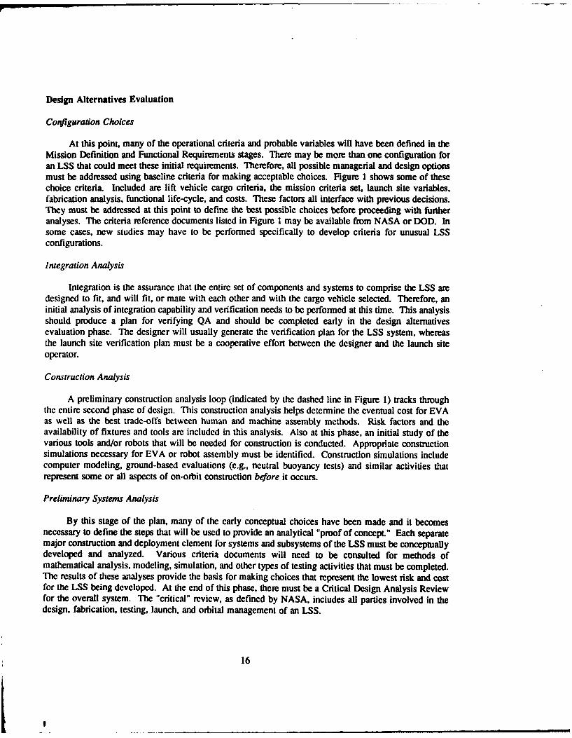
At this point, many of the operational criteria and probable variables will have been defined in theMission Definition and Functional Requirements stages. There may be more than one configuration foran LSS that could meet these initial requirements. Therefore, all possible managerial and design optionsmust be addressed using baseline criteria for making acceptable choices. Figure 1 shows some of thesechoice criteria. Included are lift vehicle cargo criteria, the mission criteria set, launch site variables,fabrication analysis, functional life-cycle, and costs. These factors all interface with previous decisions.They must be addressed at this point to define the best possible choices before proceeding with furtheranalyses. The criteria reference documents listed in Figure 1 may be available from NASA or DOD. Insome cases, new studies may have to be performed specifically to develop criteria for unusual LSSconfigurations.
Integration Analysis
Integration is the assurance that the entire set of components and systems to comprise the LSS aredesigned to fit, and will fit, or mate with each other and with the cargo vehicle selected. Therefore, aninitial analysis of integration capability and verification needs to be performed at this time. This analysisshould produce a plan for verifying QA and should be completed early in the design alternativesevaluation phase. The designer will usually generate the verification plan for the LSS system, whereasthe launch site verification plan must be a cooperative effort between the designer and the launch siteoperator.
Construction Analysis
A preliminary construction analysis loop (indicated by the dashed line in Figure 1) tracks throughthe entire second phase of design. This construction analysis helps determine the eventual cost for EVAas well as the best trade-offs between human and machine assembly methods. Risk factors and theavailability of fixtures and tools are included in this analysis. Also at this phase, an initial study of thevarious tools and/or robots that will be needed for construction is conducted. Appropriate constructionsimulations necessary for EVA or robot assembly must be identified. Construction simulations includecomputer modeling, ground-based evaluations (e.g., neutral buoyancy tests) and similar activities thatrepresent some or all aspects of on-orbit construction before it occurs.
Preliminary Systems Analysis
By this stage of the plan, many of the early conceptual choices have been made and it becomesnecessary to define the steps that will be used to provide an analytical "proof of concept." Each separatemajor construction and deployment clement for systems and subsystems of the LSS must be conceptuallydeveloped and analyzed. Various criteria documents will need to be consulted for methods ofmathematical analysis, modeling, simulation, and other types of testing activities that must be completed.The results of these analyses provide the basis for making choices that represent the lowest risk and costfor the LSS being developed. At the end of this phase, there must be a Critical Design Analysis Reviewfor the overall system. The "critical" review, as defined by NASA, includes all parties involved in thedesign, fabrication, testing, launch, and orbital management of an LSS.
16

Contractor Sequence for Systems Fabrication
This phase of development involves an evaluation of criteria that will dictate what sys-tems/subsystems are fabricated. There are two main considerations here: materials selection andperformance criteria for the systems and materials. Each of these elements may have been determinedpreviously either by tests or by analyses done in another study.
Materials for LSS
Because of atomic oxygen degradation, radiation, and the vacuum environment, materials choicescan dramatically affect life-cycle costs and mission effectiveness. Thermal cycling and launch weightmust also be considered in materials selection. The materials selected must be included for evaluation inthe overall verification plan.
Systems for LSS
At this point, many of the interfaces between the LSS system and subsystems must be defined andcoordinated to minimize expensive alteration costs. The fabrication process begins by defining scopes ofwork for contracts to firms with appropriate expertise in each component area. These contracts must becoordinated by the LSS project manager. Because of the effort involved in administering these contracts,it is important to realize that many of the tests for integration and verification must be done (even on thebasis of partial assemblies) during the fabrication phase.
Fabrication
Systems fabrication must be reviewed in terms of the vehicle integration criteria and launch fixturedesign as well as the compatibility issue. The considerations described earlier in the construction "loop"analysis must be evaluated again during the fabrication sequence to determine if the final product willpermit construction activities to occur in space. These considerations must be carried through each stageof the LSS development (hence the "loop" terminology).
The effort involved in fabrication control can be extensive. However, it is justified in order toensure quality and system integration into the LSS. In some cases, the verification and QA personnelfrom the LSS project office must work in the factory during the component processing phase to ensurecontract compliance and that full integration of parts will be possible.
Quality Assurance Verification
Integration
QA verification requires the retesting of previously tested subassemblies to be used in the LSS.Partially integrated systems tests must be conducted before assembling the complete LSS. At this stage,integration is a somewhat general term that implies physical mating, flight dynamics, and performancecl racteristics matching for all assemblies. This activity usually requires a written document for eachlaunch item.
17
I

Verification
Major elements of the verification plan developed earlier now come into play. Those aspects thatwill verify procedures, processes, and products must be addressed as the final fabricated items for the LSSare completed. Structural elements, subassemblies, and partially integrated systems all must be verified.Since an LSS has not been orbi led to date, it is apparent that the LSS designer will have had to developa verification plan that is unique to both the specific LSS system and to the choice of materials and designmethods. The verification plan that NASA developed for Space Station Freedom is the best guidanceavailable at present. The final LSS plan will require extensive development and coordination.
Ground Tests
The size of an LSS generally precludes it from being tested extensively in space; moreover, spaceis a very hostile environment and such testing would incur an extraordinary cost. For these reasons, it isnecessary to conduct as many ground tests and evaluations as possible. Time and cost can be reduced ifthis is done before the major assemblies leave the factory. Certain parts can be tested during both theverification process and the acceptance testing phase. Most of these tests can occur in the factory onpartial assemblies; however, they should have been identified at an earlier stage (as has been discussed)based on performance criteria for the LSS and cargo bay integration requirements. Questions as to howmuch the test data can be generalized from partial to whole assemblies must be addressed and anagreement reached.
Acceptance Testing/Safety Analysis
Construction "Loop" Simulation
The earlier analyses involving the construction loop, final products of the fabrication, EVA vs.robotic productivity, risk tradoffs, and cost must now be considered together. Construction loopsimulations should be made a part of the acceptance tests for the fabricated items. These simulationsmust be done before beginning the final safety analysis that will occur prior to delivering the LSS partsand components to the launch site. Simulations with a prototype would be appropriate at this stage.
Mated Parts Test
At this time, parts that have not been together in one place (i.e., made in different parts of thecountry or by different fabricators) are finally assembled and checked for mating fit and tolerances. Theyare to be checked as assemblies and subassemblies, and are processed either as major ground testcomponents or as part of final assemblies required directly or as inputs to simulations used to verify QA.Mated parts testing, with the variety of systems in an LSS, can require considerable time to accomplish.
Acceptance Testing
All major ground checks and acceptance tests, based on the earlier verification plan, must beperformed before the LSS system is shipped to the launch site. The final "sign-off' from the fabricatorto the LSS project manager is done before the process of integration into the launch vehicle begins. Itis also at this time that the launch team begins its preliminary integration review covering the launchvehicle flight characteristics, cargo bay criteria, and dimensional requirements which must be met. Thesecriteria were established early in the design phase; verification that the completed prototype parts meet
18

the criteria is now required. This is the last chance to make fabrication changes before the LSS
subassemblies and components are shipped to the launch site.
Launch Site Operations
Processing and Packing
To ensure the safety and reliability of both the surrounding environment and the launch vehicle, thelaunch site operator must be given a great degree of control over the fabricated system componentsdelivered to the site. QA and QC to ensure safety on the launch range are the launch operator'sresponsibilities. Therefore, the operator has the obligation, and usually the authority, to recheck theground test integrations of various components and to conduct a preliminary review of the LSS assemblytest for vibration, shock, and pressure that will occur when the vehicle is launched into space. Thisprocedure helps to ensure that the cargo will not be a hazard to the launch vehicle. These considerationsare used to develop a mathematical packing analysis for the payload in the cargo bay. It is the launchoperator's responsibility to conduct the final tests or checks for matching and mating subsystems.
Payload Integration
Earlier in this chapter, certain levels of integration relating to the cargo bay were identified. Certainflight vehicle mated system tests must be conducted so that components of the space structure that requirecontinuous power can be identified. Also, components that require automatic checking to ensure that theyare still operational after the launch procedure may need to be pretested in a connected configurationbetween the flight vehicle and the cargo bay. The payload integration analysis also covers structural fixingof the pallet, container, or supports that will hold the components in place inside the vehicle as it goes intoorbit. The launch shock and vibrational effects on components can be quite substantial; therefore, thelaunch site operator must verify the ability to withstand the various modes of loading through structuralanalysis of the assembled load and its supports.
Mating Operation
The final step in preparation for flight is the cargo mating operation, in which all connections andthe manifest are verified, and the previously defined construction equipment and tools are ensured to beincluded on the flight. The final integration review for the construction "loop" is conducted as part of thisactivity, and may actually have been in progress for some time. Since the assembly of an LSS consistsof several different types of construction efforts, it is quite possible that the construction loop analysis foreach flight may be quite different from the others, depending on what is being assembled or integrated.Upon verification of the cargo vehicle mating operation, the launch operator will conduct a "ready-to-launch" critical review. The purpose of this review is to ensure the success both of the launch vehicle andthe cargo it contains. Participants in this review should include representatives from all organizationsinvolved in the LSS design and fabrication, lift vehicle personnel, and the launch site operator.
Orbital Construction
Sequence
Assume that launch has occurred, the vehicle is in the required orbit, and the initial phases of theconstruction "loop" can be conducted to construct the LSS. The decision has been made previously as
19
I

to whether the LSS is to be assembled by an astronaut during EVA, a robot, or as a deployable structure.Whichever option was selected and planned earlier, a construction cycle begins, during which the activitywill consist of assembling components and subsystems followed by tests of connections, electrical andfluids continuity checks, and final verification of the whole LSS assembly. Throughout this series ofevents, there will be an emphasis on EVA (if required) in terms of medical monitoring and analysis ofhuman status. As part of the construction loop, Earth-based monitoring will be occurring and anemergency plan for rescue operations and other contingencies will be in effect. The construction sequencewill have been determined in the fielding plan-from the initial analyses done in the first stage to thesimulations completed during acceptance testing.
Assembly Processes
The assembly process at this point involves human-machine interfaces and verification for each stepcompleted. It should be noted that this process has been "designed" on a conceptual basis; the realitiesof risk and medical hazards become very real as the actual LSS construction occurs.
Productivity
The productivity needed during orbital construction, when considered with the risk factors, willdetermine the effectiveness of the LSS fielding plan. As an underlying planning principle, productivityand risk analyses will have been occurring since the very first part of the design process and will havebeen important in all planning activities. Provisions should be made to record the actual productivity andidentify any required deviations from the plan so that a valid experiential base for LSS construction duringorbit will result. The results will aid in making better plans for future operations.
Orbital Verification
Systems that could not be tested previously under zero gravity and high-vacuum conditions in theirmated states must be verified while in orbit. These tests and simulations will be part of the originalverification plan. Efforts for orbital verification should be minimized since "verification" space is not aprecise, tested concept. These activities can either be automated or conducted by astronauts. Orbitalverifications represent the last step in an LSS assembly plan.
Testing, Operations, and Maintenance
Operational Tests
The LSS must be tested as an integrated system to assure that the resulting configuration willoperate in orbit as designed and will support the initial mission objectives. This activity is part of the finalacceptance testing. The relationship between operational acceptance tests by the LSS developer and theowner (operator) of the LSS platform need to be defined in the first phase of LSS design since turnoverof the entire orbiting system will be a very important step. In other words, it must be clarified that theLSS design will not be accepted until it passes all operational tests; the basis of acceptability will havebeen accurately and completely understood as the design was developed.
20

Maintenance Analysis
Resupply logistics and repair/maintenance plans also will have been identified during the designprocess (see Figure 1). The sequence and schedule for the resupply vehicle, any docking parametersrequired, orbital transfer, and the contingency plan are documents that must be turned over to the on-orbitcontroller for operating and maintaining the LSS.
21

3 LSS FIELDING PLAN AUTOMATION
Objective of Automating the Plan
At present, there is no collation of all technologies that might apply to construction in space. Thedevelopment of a Large Space Structure Fielding Plan took a step in that direction by organizing apreliminary "road map" for identifying efforts required for LSS construction in orbit. The plan ispresented in Chapter 2 as a flow diagram of numerous interfacing activities with many variables andinformation flow that follows different paths. The complexity of this plan suggests that an automatedversion would make it easier to use. This chapter takes the initial steps in simplifying the flow diagramby organizing a management plan and installing the information on a machine. For simplicity, theinformation was organized using Wordperfect 5.0, Lotus 1-2-3, Apple Macintosh MacDraft andMacProject, and Microsoft Excel.!
As the technology matures and the information and data references are filled in, this rudimentaryplan can provide the basis, along with mission-specific information, for generating Critical Path Method(CPM) detailed plans.
Process Explanation
The organizational method used to automate the fielding plan is comparable to methods used forconstruction planning and control.
Using a construction project as an analogy, the objectives of the project (plans and specs) areidentified to initialize the process. Work areas and activities are defined and from that point, costestimates, material requirements, manhour requirements, and schedule parameters are determined usingvarious project management methods. The LSS Fielding Plan incorporates the same logic that would beused on a terrestrial construction project; however, project management is made more complex by thefollowing unique situations:
1. Material requirements (fabrication and performance)
2. Component delivery process (shuttle: capacity and expense)
3. Extravehicular Activity (EVA): (inherent danger of working in a hazardous environment).
These and many other unique situations must be considered while automating the fielding plan.However, at this level, the investigation is into an overall scenario and the development of a skeletalframework to be filled in as knowledge is gained, Since there is no precedent on which to base the plan,logic and comparison to terrestrial project management techniques were incorporated.
This phase breaks the existing fielding plan into manageable elements. These elements are basedon hierarchial relationships, three of which of have been established: (1) work phases (2) activities and(3) tasks.
2Mention of cradenames does not constitute endorsement.
22

Work phases (assigned numeric codes) represent the initial breakdown of the overall plan fromwhich seven categories have been identified. The numerical code used to designate the phases (05-35)is designated and spaced to allow for activities that may be determined or identified later.
OS LSS MISSION DEFINITION/FUNCTIONAL REQUIREMENTS
10 DESIGN ALTERNATIVES EVALUATION
15 CONTRACTOR SEQUENCE FOR LSS SYSTEM FABRICATION
20 QUALITY ASSURANCE VERIFICATION/ACCEPTANCETESTS/SAFETY ANALYSIS
25 LAUNCH SITE OPERATIONS
30 ORBITAL CONSTRUCTION
35 OPERATIONS AND MAINTENANCE ACTIVITY
The second level of the breakdown hierarchy divides "work phases" into manageable elements thatwill be defined as activities and assigned alphabetic codes. Activities demonstrate the flexibility ofdefining a work breakdown structure. Several activities may be planned and the level of detail in whichthese activities are accomplished in terms of "phases" depends on the complexity of the project. Thismethod of organization is ideal for an LSS Fielding Plan due to the complexity and vast coordinationrequirements of an LSS project.
The third level of the breakdown hierarchy divides "activities" into manageable elements that aredefined as tasks and assigned numeric codes. For LSS fielding plan purposes, a task is a unique unit ofwork or decision making which may span several work areas (i.e,, quality assurance and quality controlchecks).
Example: 05 WORK PHASEA. Activity
1. Task
These three levels can provide management devices at the three degrees of need to know. Forexample, program managers may use the first two levels of the hierarchy to track project development.Project managers may use levels two and three to provide detailed insight into status. System or elementperformers may use level three, with supporting identified reference documents, as their detailed guidanceand refer to levels two and one for sense as to where their work fits into the scheme of things.
Diagrammatic Work Breakdown Structure
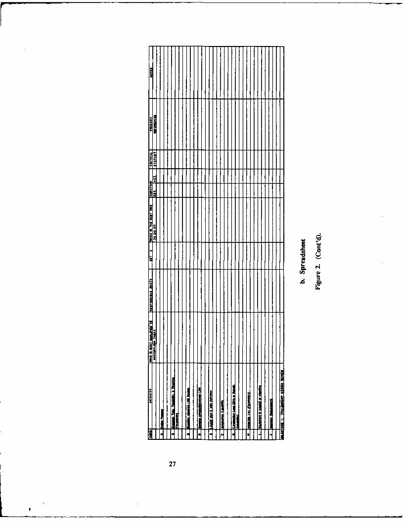
The seven work phases identified in the previous section have each been arranged into individualflow charts. This arrangement provides a quick reference to relationships between activities and tasks withrespect to a specific work area. It is designed to give a general indication of precedence betweenactivities. The chart should be read from top to bottom and left to right. However, it should be notedthat actual duration of tasks, which may vary to a large degree, depends on the specific mission.Immediately following the flow chart is a spreadsheet that examines each task in terms of qualification
23

for completion, costs, time/duration, milestones, status, and references (see the Appendix for anexplanation of each parameter). This study does not apply the duration parameter. Recently developedsoftware uses "what if" mission scenarios sensitive to time, and other mission specific examples.'
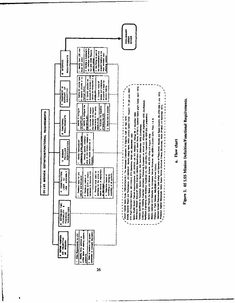
The following text demonstrates each work phase of the LSS Fielding plan organized into amanageable work breakdown structure in (1) outline, (2) flow chart (diagrammatic), and (3) spreadsheetformats. The latter two are shown in Figures 2 through 7.
Large Scale Programs Insitute (Austin. TX) Lunar Base Model (LBM) Version 3.0 is a PC-based mission planning and
system integration tool that provides a quantitative assessment of lunar base program options.
24

05 LSS MISSION DEFINITION/FUNCTIONAL REQUIREMENTS
A. Define Purpose and Objective of Mission
1. State the requirements for the LSS2. Identify items common to similar types of orbiting stations and platforms3. Refer to baseline LSS system (schematic or conceptual) description
B. Establish Time, Feasibility, & Financial Parameters
C. Construction Loop for LSS Assembly
I. Establish basis for procedures and techniques2. Decide on method of assembly (EVA) or necessary to fabricate LSS3. Provide initial basis for estimates for the actual in-space activity of deployment or
fabrication4. Determine means of controlling or managing assembly of all systems
D. Mission Peculiar Activity Identification
I. Identify standardized components of the LSS system2. Identify specific characteristics of LSS function (related to earlier stated objectives of the
mission)
E. Functional Requirements
1. Identify and configure managerial plan2. Identify and configure the engineering plan3. Consider the relationship between the mission requirements and the components (material
fabrication & performance requirements)
F. Equipment in Support of Objective
I. Define lift vehicle type and capacity (shuttle or unmanned rocket)2. Identify sequences of launches if LSS cannot be transported in a single trip3. Compile trade-off studies and simplexes to provide a basis for decision-making
G. Interface Requirements
1. Identify how LSS interfaces will occur2. Develop a supplementary interface documentation plan (Data Requirements Listing)'3. Use listing as part of the documentation and analysis leading to the most workable cost-
effective solution
Document requiring submitted and approval by NASA before the preliminary design review.
25
" li lTar- &" I-11 g"i
.0m
w eww
-0.0
z
, w o r: e* I4 w = 0==
0 - 6..---' -
- w f'i ,t .. .. . .. . -I . .. ,-
0
17
&i ~A I"
--- -- - --- -- tj
,', .2
">Ill iIl~ l~ S. i
i : c z
-I is E
Ii I I
- - - - -
>1 0
o r,'
N26
aal
27

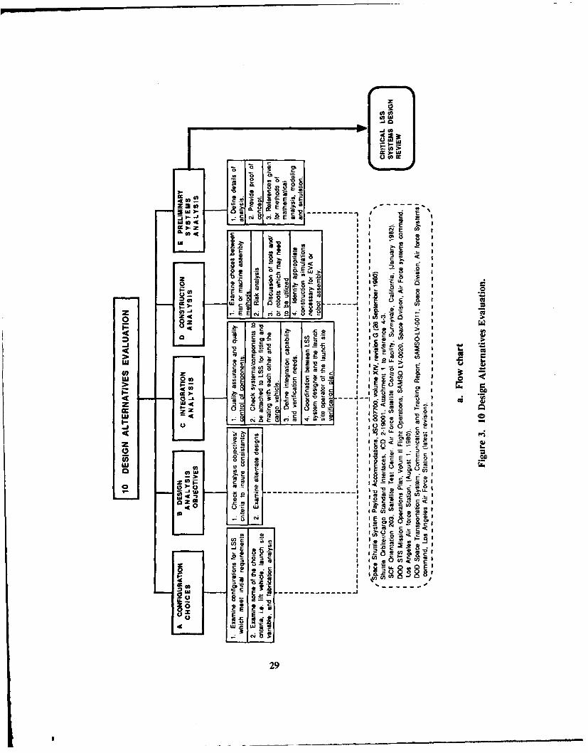
10 DESIGN ALTERNATIVES EVALUATIONA. Configuration Choices
1. Examine alternative configurations of LSS that will meet mission objectives2. Examine choice criteria (i.e., launch site variables fabrication analysis, etc...)
B. Design Analysis Objectives - Alternate Designs
1. Check design analysis of objectives and choice - criteria consistency2. If analysis objectives and choice criteria are inconsistent, enter "loop" & examine alternate
designs
C. Integration Analysis
1. Perform quality assurance and quality control for components2. Verify components and systems to be attached to LSS will fit with the LSS and with the
cargo vehicle selected3. Define integration capability and verification needs4. Coordination launch site verification plan between the LSS system designer and the launch
site operator
D. Construction Analysis
1. Examine trade assembly choices between man or machine assembly methods (erectable vs.deployable)
2. Conduct risk analysis3. Determine what tools and/or robots will be needed4. Identify appropriate construction simulations necessary for EVA or robot assembly
E. Preliminary System Analysis
1. Define detailed analysis steps2. Perform analysis3. Provide analytical proof of concept4. Reference various criteria documents for methods of mathematical analysis, modeling and
simulation
28
I
z
0
~~ am
LAII
I Cl
z I
EUl >.
000
go5c '
to-
29.

4.
U-
L.
C,,6
0*
I
-I
a
30

15 CONTRACTOR SEQUENCE FOR LSS SYSTEM FABRICATIONA. Material Evaluation and Selection Criteria
1. Consider hazardous conditions of space (atomic oxygen, temperature, etc.)2. Determine required or expected life cycle of structure3. Select material capable of meeting requirement based on (1&2)4. Evaluate materials based on all parameters including thermal cycling and launch weight5. Choose "best" material to perform in given environment (preferably material that has been
preselected space (qualified)6. Optimize life cycle costs and mission effectiveness
B. Systems for LSS
1. Identify systems (structural, mechanism controls, attitude control...)2. Prepare contracts and subcontracts by defining scope of work3. Advertise, evaluate, and award contract4. Coordinate work and supervision to insure full integration of all features of the design5. Conduct testing relating to integration and verification
C. Fabrication
1. Review vehicle integration criteria and launch fixture design2. Review fabrication loop analysis3. Exercise fabrication control
31
. . . .

cc 4
a 8l
0~~~~- ----------
-E-
IC0I
02 *-
LU
-c -a .r eCO~
o~ ~ L c4 . ----
Z~ ccl * C28 ~Inr 0 0 ~ . ~
_ _ I8c *0~
0 08
jc His a
N ~ ~I k Am
iiiilI
U32
It

M il II-
33
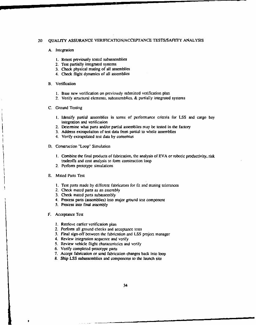
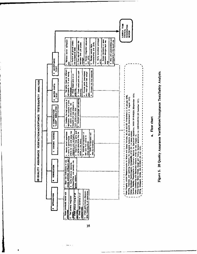
20 QUALITY ASSURANCE VERIFICATION/ACCEPTANCE TESTS/SAFETY ANALYSIS
A. Integration
1. Retest previously tested subassemblies2. Test partially integrated systems3. Check physical mating of all assemblies4. Check flight dynamics of all assemblies
B. Verification
1. Base new verification on previously submitted verification plan2. Verify structural elements, subassemblies, & partially integrated systems
C. Ground Testing
1. Identify partial assemblies in terms of performance criteria for LSS and cargo bayintegration and verification
2. Determine what parts and/or partial assemblies may be tested in the factory3. Address extrapolation of test data from partial to whole assemblies4. Verify extrapolated test data by consensus
D. Construction "Loop" Simulation
1. Combine the final products of fabrication, the analysis of EVA or robotic productivity, risktradeoffs and cost analysis to form construction loop
2. Perform prototype simulations
E. Mated Parts Test
1. Test parts made by different fabricators for fit and mating tolerances2. Check mated parts as an assembly3. Check mated parts subassembly4. Process parts (assemblies) into major ground test component5. Process into final assembly
F. Acceptance Test
1. Retrieve earlier verification plan2. Perform all ground checks and acceptance tests3. Final sign-off between the fabrication and LSS project manager4. Review integration sequence and verify5. Review vehicle flight characteristics and verify6. Verify completed prototype parts7. Accept fabrication or send fabrication changes back into loop8. Ship LSS subassemblies and components to the launch site
34
9
Z o e l
uJ
- 1 - -
: ~r_
CL a
0- - -i S " ;
-,-W
( A . * & a
cii
. ;) I a
.- 2 -e
cci1.------------------ I I
- fly a00 8
00 C)
in E 2 S .0
C)
I
02 z
IU E 8:-
I.e _a
35

3
a,
4.
o -~oo a
C
a..
I
36
1

25 LAUNCH SITE OPERATIONS
A, Processing and Packing
1. Recheck ground test integration of various components2. Conduct preliminary review of LSS assembly test (vibration, shock, & pressure)3. Develop mathematical packing analysis for the payload4. Conduct final tests for matching and mating subsystems
B. Payload Integration
1. Conduct payload integration analysis2. Conduct structural fixing of the pallet, container, or supports which will hold the
components in place3. Condu.t structural analysis of the assembled load and its supports4. Verify capability of assembled load to withstand various modes of loading (launch shock
and vibration effects) in the vehicle as it goes from the launch pad into orbit
C. Mating Operation
1. Conduct cargo mating operation2. Verify all connections3. Verify manifest4. Assure needs for previously defined construction equipment is assured for the flight5. Perform final integration review for the construction loop6. Conduct "road-to-launch" critical review
37

Iv
-r
Li
zo 2 3: -
o -. ® O
g 2 .0c 4) 0 iz U)
0 .0 u E 1
u ---- I M o)
• U.- a. "Ez
0 : 0> a' E 0 -i
O0.E E (D 2. E0 co > c
000 o
00 00 S E~ 0 >"CL~1 0% 0-00
3U0 0~ wO T .2
w < °'
n =4 .
380
.00. 0'z~~~~ 0 ,
a~0 Q.I 0 C
;8
L-: - tc n 0 - t '

CL
39

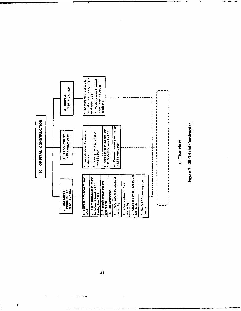
30 ORBITAL CONSTRUCTION
A. Assembly Process and Sequencing
1. Examine man-machine interfaces2. Verify procedures in assembly sequence based on LSS Fielding Plan CPM3. Assemble components and subsystems4. Test connections5. Check system for electrical continuity6. Check system for fluid continuity7. Check system for mechanical continuity8. Verify LSS assembly continuity
B. Productivity Measurements
1. Note duration of assembly activities2. Identify required durations form LSS Plan3. Note discrepancies and establish experience base for LSS4. Evaluate overall effectiveness of LSS Fielding Plan
C. Orbital Verification
1. Conduct test and simulations of systems using original verification plan2. Verify systems in mated states at zero g.
40
9
E; o
--E ES I'
3 0
SI >
0o Z ; 0
>I Ius 0
-& ------ ------Ix
4c- Zc
>, co Q
0
I
F a.
o -o.
u0
S s
I 0
Cl))
41*>,
0 ii
oo

I-
'4
4.
B
-o.~ 0U,
~ wI..
a
IU
42

35 OPERATIONS AND MAINTENANCE ACTIVITY
A. Operations
1. Test LSS system configuration on orbit
B. Maintenance Analysis
1. Determine sequence and schedule plan for the resupply vehicle, any docking processesrequired, and orbital transfer maneuvers
43

2 z
-0 CLI
z
0 t
C 00
ca L.
c ca0-- 1J 5<
CL I- 0 0
o1
0. I
o a I 144

45
4 CONCLUSIONS AND RECOMMENDATIONS
A plan has been proposed for fielding LSS. The plan includes logical sequences of activities andidentifies the interface/integration points that must be addressed.
This fielding plan should be used as the basis for compiling an automated program that can beupdated and expanded as necessary for efficiency. In addition, careful consideration should be given toforming a space construction data bank to contain an organized, systematic set of information and designdata for LSS project engineers and managers.
Many elements within the fielding plan lack supporting reference documents. Studies are neededto fill these voids.
Bibliography
Specifcations, Standards, and Regulations
AF Regulation (AF REG) 100-45. Vols 1 and I (S), Change 1 (U.S. Air Force. 1 April 1982).
AF REG 0-5. Index of Specialized Tempest Comsec Documents (U.S. Air Force, Latest Issue).
AFM 88-4, Criteria for Air Force Clean Facility Design and Construction. Chapter 5 (U.S. Air Force, 9 September 1968).
ASTM E595. Method of Test For Total Mass Loss and Volatile Condensable Materials for Outgassing in a Vacuum Environment,(American Society for Testing and Materials [ASTMI, 1977).
Compilation of VCM Data on Non-Metallic Materials, JSC 08962 (NASA, Latest Revision).
Contamination Control Handbook, NASA CR-61264 (NASA. 1 December 1969).
Contamination Control of Aerospace Facilities AF T.O. 00-25-203, Change 4 (11 December 1978).
Criterions for Installing Classified Information Processing Equipment on Aircraft (U), AFNAG-2B (U.S. Air Force, September1972) (Confidential).
Design Handbook Electromagnetic Compatibility, AFSC DH 1-4 (Latest Edition).
DOD 5200.1-R. Information Security Program Regulation, (DOD. 17 October 1980).
DOD Information Security Program. AFSCP 207-1 (DOD, 1 June 1982).
DOD Space Transportation System (STS) Communication and Tracking Report, SAMSO-LV-001 1 (Space Division, Air ForceSystems Command. Latest Revision).
ID)1) STS Mission Operations Plan, Vohme II Flight Operations, SAMSO LV-0020 (Space Division, Air Force SystemsCommand, August 1, 1980).
DOD-W-8357A, General Specifications for Wiring Hardness. Space Vehicle. Design and Testing (DOD, 22 December 1977).
FED-STD-209B, Clean Room and Work Station Requirements. Controlled Environment Amendment 1 (30 May 1976).
46
___

Get Away Special (GAS) Small Self-Contained Payloads NASA Experimenter Handbook (Goddard Space Flight Center,Sounding Rocket Division, October 1979).
Integration and Ground Turnaround Contamination Control Plan K-STSM-09.7A NASA KSC (April 1979).
Launch Vehicle Users Guide, TOR-0073 (3419)-I (The Aerospace Corp., 21 May 1975).
List of Materials Meetint JSC Vacuum Stability Requirements, JSC 07572 (NASA, Latest Revision).
Long Duration Exposure Facility (LDEF) Guide for Experimenters Accommodations User Handbook NASA Report, MS 258(Langley Research Center. 15 January 1978).
MIL-B-5087B. Bonding. Electrical, and Lightning Protection for Aerospace Systems, Amendment 2 (DOD. 31 August 1970.)
MIL-HDBK-5. Metallic Materials and Elements for Aerospace Vehicle Structures (DOD. Current Edition). parts 1 and 2.
MIL-HDBK-17. Plastics for Flight Vehicles (DOD, Current Edition).
MIL-M-38310B. Mass Property Control Requirements for Missile and Space Vehicles Amendment 2 (DOD. 31 August 1976).
MIL-STD-1246A. Specification, Contamination Control Requirements for the Space Shuttle Program. (DOD. 18 August 1967).
MIL-STD-1512, Electroexplosive Subsystem, Electrically Initiated. Design Requirements and Test Methods (Department ofDefense [DOD]. 21 March 1972).
MIL-STD-1522. Standard General Requirements for Safe Design and Operation of Pressurized Missileand Space Systems. (DOD. 1 July 1972).
MIL-STD-1574A. System Safety Program for Space and Missiles Systems (DOD. 15 August 1979).
MIL-W-5088H, Wiring. Aerospace Vehicle (DOD. 20 July 1979).
Mission Integration Guidelines for Development of STS Attached Payloads, NASA/MSFC JA-172 (NASA, December 1981).
Multi-Mission Modular Spacecraft (MMS) External Interface Specification and User's Guide, S-700-11, (Goddard Space FlightCenter, April 1978).
NASA JSC Requirements for Materials and Processes NASA JSC, SE-R-0006 (NASA. 29 March 1976).
NASA/DOD STS System Security Plan, SD-YV-0047 (19 June 1982).
Orbiter Middeck Payload Provisions Handbook, NASA JSC 16536 (NASA, July 1980).
Power Conditioning and Distribution Network. AFSC DH 302, ChaptCr 15.
Protection Against Meteoroids, NASA Space Vehicle Structural Criteria (Structures). NASA SP-8042 (NASA, 15 November1971).
Red/Black Engineering and Installation Guidelines, NAC SEM-5203 (to Supersede MIL-HDBK -232; in preparation).
Safety. Reliability, Maintainability, and Ouality Provisions for the Space Shuttle Program, NASA NHB 5300.4 (ID-2) (DOD,October 1979).
SCF Orientation SCF 203 (Satellite Test Center, Air Force Satellite Control Facility, January 1982).
Shuttle EVA Description and Design Criteria JSC 10615 (NASA, May 1976).
Shuttle Poindw of Electro-O1xical Exoeriments, SPIE, Vol 265 (February 1981)
47
6

Shuttle OrbiteriCarzo Standard Interfaces, ICD 2-19001, Attachment 1 to Reference 4-3.
Shuttle Systems Weight and Performance JSC-090095-61, Monthly Status Report, (NASA Johnson Space Center. 28 June 1982).
Space Shuttle System Contamination Control Plan, JSC 08131 (NASA, 21 August 1975).
Space Shuttle System Payload Accommodations, JSC 07700. Vol XIV. Revision G (NASA. 26 September 1979).
Space Shuttle System Payload Accommodations JSC 07700, Vol XIV. Revision G. Change 39 (NASA, 1 November 1982).
Space Shuttle System Pyrotechnic Specification, JSC-08060B (NASA. 12 February 1977).
STS Flieht Assignment Baseline, JSC-13000-8, STS Operations, (NASA, November 1982).
STS Ground Safety Handbook, SAMTO HB S100 (24 September 1982).
STS Integration and Operational Requirements for STS Compatible Spacecraft PIOS Planning Guide, Appendix C, SD-YO-0001(18 January 1982).
STS Security Classification Guide (HQ Space Division [AFSC]. Los Angeles Air Force Station. 20 January 1982).
System Safety Certification Procedures and Technical Requirements for DOD Space Transportation System Payloads, SDR 127-4(1 October 1981).
System Safety Engineerin, SAMSO REG. 127-8 (11 September 1978).
Tempest Guidelines for Equipment. System Desirn, NAC SEM-5201 (September 1978) (C).
Vacuum Stability Requirements of Polymeric Material for Spacecraft Application, NASA SP-R-0022A (9 September 1974).
Terms and Abbreviations
Terms
Construction loop Integration: user developed scenario which integrates all EVA and automation for LSS assembly; writtenplan and interface to all other documents
Construction loop verification: identification and integration of assembly simulations to provide accurate ground test for LSSassembly sequence, including test and analysis results
Data requirements listing: list of required documents which describe the LSS concept and all decision logic and criteriaavailable at the tine. It consists of drawings, materials, schematics, and safety analysis; the documents should beprovided by the LSS sponsor.
Cost/risk analyses: must be performed early in design process, since erectable/deployable variables and lift vehicle criteria willaffect LSS costs
Integration analysis document: by LSS sponsor to define level of confidence and required testing for parts which will be matedinto overall LSS system during construction in orbit
Large space structural orbital test plan: LSS sponsor developed; must be designed for QC/QA since nothing of this scale hasbeen designed and flown
48
Terms and Abbreviations (Cont'd)
Operations and maintenance plan: user developed document with emphasis on resupply mission and schedule for maintenanceon orbit, including cost estimates
Subsystem criteria: generic and DOD standards that exist for some components; for most LSS systems, new standards mustbe defined and fabrication criteria developed
Abbreviations
EVA: extravehicular activity
QA: quality assurance
QC: quality control
49
APPENDIX:
SPREADSHEET KEY
Title - at top of page designates the work phase with the assigned work number. Seven (7) work phaseshave been identified from the fielding plan thus far, however addition/expansion as new work areas areidentified is possible.
Code - the alphabetic code assigned to all the activities comprising a specific work phase (A-Z).
Who is best qualified to accomplish task?This is a question of operational management. Obviously, the person or group which specializes in thatparticular area is best qualified. However, some tasks for LSS construction and operations are state-of-the-art and therefore have no parameters or precedence by which to determine who or what group is bestqualified to execute it.
Responsible EntityThis question addresses the identification of the major or parent entities involved with the specific activity(i.e. NASA, DOD, Army Corps of Engineers, etc...). Some responsibilities for activities may be jointefforts and will be identified as such.
Estimated Costs ($)?This area is designed to address rough estimates of the total costs associated with executing the activity.Whether or not this is an issue that should be accessible by other users of the automated fielding plan isin question.
When is the best time to do it?The parameter of the term "when" addresses questions of precedence with the work phases, activities, andtasks in the scope of the entire fielding plan. Also, this question should include concerns about groundbased testing or testing on orbit.
DurationExamines how long it will take to execute (at the activity level) in terms of days/months/years beginningwith the estimated duration noted next to the actual duration to be fllcd in at a later date. Becauseresearch in this area is in its infancy, it is difficult to address the activities using time as a parameter atthis point. This can be filled in as research advances.
Critical Status?Examines the activity in terms of the entire plan. Asks whether or not a particular task must be completedbefore moving on to the next activity and ultimately the next work phase. If the plan cannot move intothe next work phase until the this activity is completed, then it is considered to have critical status.
Primary ReferencesIf reference material exists on a particular activity - the primary sources will be noted. A reference librarydatabase must be created and keyed to the automated fielding plan so that each reference can be assignedan alpha-numeric code to be used as a citation.
50

NotesDocuments any pertinent information or extenuating circumstances not covered in the given categories.
Milestone - (located in bottom left comer of spreadsheet) indicates that a review has been performed andall activities and tasks of the work phase have been completed and no loops need to occur (if adiscrepancy occurs, it can be identified and addressed using a loop format thus eliminating the need toalways start from the beginning of the work phase). If there are no discrepancies, the completion of themilestone gives the signal to move on the next work phase. The following are decision point milestonesfor each work phase in the LSS fielding plan.
1. Preliminary Design Review
2. Critical LSS Systems Design Review
3. Launch Team Review and Analysis
4. Launch Team Critical Integration Review
5. Launch
6. Construction Completion
7. Orbital Operations LSS Acceptance Test
51

DISTRIBUTION
Chief of EngineersATN: CERD-MATTN: CEHSC-IM-LP (2)ATTN: CEHSC-IM-LG (2)ATTN: CEMP-CATTN: CEMP-CATrN: CERD-LATTN: CERD-CATTN: CERMATTN: DAEN-ZCI
US Militaxy Academy 10966ATTN: Dept of Geography &
Computer ScienceATTN: MAEN-A
Army Matis Technology Lab 02172ATTN: Library
Harry Diamond Laboratories 20783ATTN: HQLABCOM
INSCOM - Ch, Instl. Div.Arlington Hall Station (4) 22212AfN: Library
Vint Hill Farms Station 22186ATTN: Library. ASTRO
TRADOCFort Leavenworth 66027
ATTN: USASIFort Leonard Wood 65473
ATTN: USAES
Fort Belvoir 22060ATTN: Engr Topographic Lab. CEETL-RI-SATrN: CECC-R
CECRL. ATrN: Library 03755
CEWES. ATIN: Library 39180
Tyndall AFB, FL 32403AFESC/Engineering & Service Lab
NCEL 93043ATTN: Library (Code L08A)
NIST 20899
Defense Technical Info. Center 22314
ATTN: DDA (2)
321/91
'p
S = it