large-scale experimental wind-driven rain exposure
TRANSCRIPT

Submitted for publication in Solar Energy, 2012.
Large-Scale Experimental Wind-Driven Rain Exposure Investigations of Building Integrated Photovoltaics
Christer Breivik a, Bjørn Petter Jelle ab*, Berit Time b, Øystein Holmberget b, John Nygård b, Einar Bergheim b and Arvid Dalehaug a
a Department of Civil and Transport Engineering,
Norwegian University of Science and Technology (NTNU), NO-7491 Trondheim, Norway.
b Department of Materials and Structures, SINTEF Building and Infrastructure, NO-7465 Trondheim, Norway.
* Corresponding author, [email protected], Phone +47 73 593377, Fax +47 73 593380
Abstract
Building integrated photovoltaics (BIPVs) are photovoltaic materials that replace conventional building materials in parts of the building envelopes, such as roofs or facades, i.e. the BIPV system serves dual purposes, as both a building envelope material and a power generator. Hence, it is important to focus on the building envelope properties of a BIPV system in addition to energy generation performance when conducting experimental investigations of BIPVs. The aim of this work was to illustrate challenges linked to the building envelope properties of a BIPV system, and to develop and evaluate relevant methods for testing the building envelope properties of BIPV systems.
A sample roof area with two BIPV modules was built and tested in a turnable box for rain and wind tightness testing of sloping building surfaces with the aim of investigating the rain tightness of the BIPV system, and observing how it withstood wind-driven rain at large-scale conditions. The BIPV sample roof went through testing with run-off water and wind-driven rain with incremental pulsating positive differential pressure over the sample at two different inclinations. The BIPV sample roof was during testing constantly visually monitored, and various leakage points were detected. In order to prevent such water penetration, the steel fittings surrounding the BIPV modules should ideally be better adapted to the BIPV modules and constricted to some extent. It is however important to maintain a sufficient ventilation rate simultaneously.
Keywords: Building integrated photovoltaic, BIPV, Solar cell, Roof, Experiment, Rain tightness.
Submitted for publication in Solar Energy, 2012. 2
Contents
1. Introduction .......................................................................................................................... 3
2. Experimental......................................................................................................................... 4
2.1. Sample materials and components ........................................................................................... 4
2.2. Test method ................................................................................................................................ 6
2.2.1. Test phase 1 - Run-off water without wind pressure ......................................................... 6
2.2.2. Test phase 2 - Run-off water and wind-driven rain with pulsating positive differential pressure over the wind barrier...................................................................................................... 7
2.2.3. Test phase 3 - Run-off water and wind-driven rain with pulsating positive differential pressure over the BIPV modules integrated with a steel plate roofing ........................................ 7
3. Results and discussion.......................................................................................................... 7
4. Conclusions ......................................................................................................................... 11
Acknowledgements................................................................................................................. 12
References ............................................................................................................................... 12

Submitted for publication in Solar Energy, 2012. 3
1. Introduction Globally, there is an ever increasing demand and focus on renewable and non-polluting energy sources. Meanwhile, the world is consuming fossil fuel resources at an alarming rate. With emissions of 10.9 gigatonnes of carbon dioxide equivalents (GtCO2e) per year in 2005, the power industry is responsible for 24 % of global Greenhouse Gas (GHG) emissions, and this is expected to increase to 18.7 GtCO2e per year in 2030 (McKinsey 2009). “Carbon dioxide equivalent is the unit for emissions that, for a given mixture and amount of greenhouse gas, represents the amount of CO2 that would have the same global warming potential (GWP) when measured over a specified timescale (generally, 100 years)” (McKinsey 2009).
Within this context, zero energy and zero emission buildings are rapidly drawing attention, and in order to become a zero energy or zero emission building, the building will normally need to harvest energy from its surroundings. Energy from the sun is one of the obvious choices, and of all the renewable energy sources currently available, it is the most abundant, inexhaustible and clean one (Peng et al. 2011). In one day, the irradiation from the sun on the earth gives about 10 000 times more energy than the daily use of mankind (Swiss BiPV Competence Centre 2010).
Photovoltaics (PV) may produce electricity on site, directly from the sun, without any concern for energy supply or environmental harm (Strong 2011). Building integrated photovoltaic (BIPV) systems replace parts of the conventional building materials in the building’s climate envelope, such as the roof covering and facades. To be classified as a BIPV system, the system must be considered as a functional part of the building structure, or it must be architecturally integrated into the building’s design (Peng et al. 2011). Hence, the BIPV system serves as a building envelope material and power generator simultaneously (Strong 2011). That is, the BIPV system must fulfil the requirements of both the building envelope material and construction, and the PV solar cells. For a state-of-the-art review and future research opportunities within various aspects of BIPVs it is referred to the studies by Jelle et al. (2012), Jelle and Breivik (2012a) and Jelle and Breivik (2012b). Investigations of various cost aspects like life cycle cost (LCC), embodied energy and energy payback times for BIPVs have been carried out by Chel et al. (2009), Eiffert and Kiss (2000), Eiffert (2003) and Hammond et al. (2012). Furthermore, a comprehensive study for enhancing the performance of BIPVs has been performed by Norton et al. (2011). In general, accelerated climate ageing of building materials, components and structures, may readily be carried out in the laboratory, where new materials and products like e.g. various BIPV systems may be of special interest and importance (Jelle 2012).
Wind-driven rain is one of the most important moisture sources affecting the hygrothermal performance and the durability of building facades and roofs (Blocken and Carmeliet 2004, Blocken and Carmeliet 2012, Eldridge 1976). A BIPV module replacing the roof covering has to be rain proof above all. Infiltration of water in discontinuous roof coverings may principally depend on factors such as the roof slope, the external wind pressure creating a pressure gradient between the inside and the outside of the building, the quantity of streaming water, the joint dimensions, the surface tension between the water and the fixings, the quantity and nature of dirt present, etc. (Fasana and Nelva 2011).
Different methodologies for evaluation of rain tightness of discontinuous roofing systems have been tested in the world. E.g. at the French Technical Center for Tiles and Bricks (CTTB) where an open sloping wind tunnel that exposed a test specimen to grazing wind, streaming water, and an applied

Submitted for publication in Solar Energy, 2012. 4
differential air pressure between the outside and the inside of the roof was experimented (Fasana and Nelva 2011). In England a large closed wind tunnel has been built where the roof specimen is placed in the centre of the section of the horizontal wind tunnel (Fasana and Nelva 2011, Hazelwood 1979).
Regarding BIPV systems, some climate testings, both outdoor and indoor, have been undertaken, by e.g. Bloem (2008), Mani et al. (2009) and Mei et al. (2009), whereas mechanical testing has been carried out by e.g. Jol et al. (2009). Basic studies on irradiance and energy output, including temperature and generation performance, of PV/BIPV systems and modules have been performed (Carr and Pryor 2004, Celik 2003, Chenni et al. 2007, Mattei et al. 2006, Smiley 2001). Many BIPV manufacturers state that their products contain innovative rain tightness systems for extreme conditions. However, in total, very few experimental tests, including at controlled laboratory conditions, of rain tightness of BIPV systems have been conducted and reported in the available literature.
Based on this background, the main objective of this work was to investigate the rain tightness of a specific BIPV module product integrated in a roof construction, and evaluate how it withstood precipitation in form of wind-driven rain at large-scale conditions, using a turnable box for rain and wind tightness testing of sloping building surfaces. The second objective was to develop and evaluate relevant methods for testing BIPV systems regarding their building envelope properties. The experimental set-up enabled a controlled test environment. Rain tightness of various BIPV modules must however be specified according to the water tightness of the underroof, and its drainage and drying-out capability.
2. Experimental
2.1. Sample materials and components A sample roof area with dimensions 2.75 m x 2.75 m was built on a wooden frame using a transparent polycarbonate (Lexan) board as wind barrier, and with double furring strips (23 mm x 36 mm vertically and 36 mm x 48 mm horizontally on top) as shown in fig. 1 (left). Two DuPont Gevity - 165M BIPV modules, with dimensions as presented in table 1, were mounted together (side by side) onto the furring strips using the adaptable flashing system which allows flashing between the modules as depicted in fig. 2.
Table 1: Basic physical data (DuPont 2010). See also the studies by Jelle and Breivik (2012a) and Jelle et al. (2012) for information about DuPont Gevity.
Product Area Free space in frame
Glass thickness
Frame weight Cells Flashing
material DuPont Gevity 165M
1332.5 mm x 929 mm
820 mm x 1304 mm x
6 mm 4 mm < 5.4 kg
5x8 mono-crystalline
silicon cells
Pre-coloured galvanised
steel The limited size of the apparatus, although a large-scale apparatus, made it impossible to mount more than two BIPV modules together onto the sample roof. The BIPV modules were then surrounded by tailor-made steel fittings from DuPont as shown in fig. 1 (right). A 0.5 mm thick cold-rolled steel plate roofing (Isola Powertekk tile) was installed around the BIPV panels using 4.5 mm x 70 mm wood screws (Isola 2012). A heavy-duty siliconised paper (DuPont FlexWrap NF) was used as a seal between the steel roofing and the tailor-made DuPont steel fittings (DuPont 2008). The completed BIPV roof area is shown in fig. 3.

Submitted for publication in Solar Energy, 2012. 5
The specific BIPV system for these experimental investigations was chosen among many other BIPV systems as presented by Jelle et al. (2012). A BIPV module product (DuPont Gevity) was chosen, which in fact has one of the highest solar cell efficiencies (17.7 %) reported in the state-of-the-art review by Jelle et al. (2012), only maybe surpassed by the C21 tile and slate from Solar Century of 20 % per cell, and the solar glazing system from Sapa Building System of 22 % per cell, where the efficiency naturally will be lower for a whole tile, module or glazing area product. A high solar cell efficiency is of course important in order to harvest as much solar energy as possible within a given area, and thereby be able to fulfil the requirements of e.g. zero energy and zero emission buildings.
Fig. 1: Roof area with transparent Lexan board wind barrier with double furring strips (left), and the two DuPont Gevity - 165M BIPV modules surrounded by the tailor-made steel fittings from DuPont (right).
Fig. 2: Sleeve system which allows flashing between the modules (left) with detailed drawing of the sleeve flashing system splice (right) (DuPont 2010).
Fig. 3: Completed BIPV roof area with steel plate roofing.

Submitted for publication in Solar Energy, 2012. 6
2.2. Test method The experimental testing was conducted in a large-scale turnable box for rain and wind tightness testing of sloping building surfaces (RAWI box) as depicted to the left in fig. 4. The RAWI box allows stepless variable inclination, controlled differential air pressure across the test specimen, running run-off water at the top of the test area, and spraying of wind-driven rain across the test area from a horizontal boom (row) (fig. 5, right) which moves back and forth (up and down) along the sample 0.6 m above the exterior roof surface. The sample roof was installed in the RAWI box as shown in fig. 4 (left and right), and the testing was carried out according to the principles given in EN 12865 and NT Build 421 with some minor modifications (European Committee for Standardization 2001, Nordtest Method NT Build 421, 1993). The rain tightness test was divided into three phases, as shown in table 2.
Table 2: Test phases for the large-scale turnable box for rain and wind tightness testing of sloping building surfaces (RAWI box).
Test phase 1 Test phase 2 Test phase 3
Run-off water without wind
pressure.
Run-off water and wind-driven rain with pulsating positive differential pressure (overpressure) over the
wind barrier.
Run-off water and wind-driven rain with pulsating positive differential pressure (overpressure) over the BIPV modules integrated with a steel plate roofing.
Fig. 4: Visual inspection of BIPV sample roof from below the inclined RAWI box (left) and sample roof inside the RAWI box during testing, viewed from outside the box through a window (right). The coloured ellipses denote leakage points.
2.2.1. Test phase 1 - Run-off water without wind pressure During test phase 1 the BIPV sample roof was only exposed to run-off water without wind pressure or wind-driven rain. This was conducted at two different inclinations (30 and 15 degrees) for 10 minutes each (table 3). The run-off water was applied through a row of tubes situated just above the top of the sample, at a rate of 1.7 dm3/(m min) (Pedersen et al. 2008). During test phase 1 the BIPV sample roof was constantly and carefully visually monitored from below through the transparent wind barrier (fig. 4, left) with the purpose of observing any possible water leaks. After test phase 1 was completed, the sample roof was taken out of the RAWI box and thoroughly dried with a fan heater, as shown to the left in fig. 5.

Submitted for publication in Solar Energy, 2012. 7
Fig. 5: Drying of BIPV sample roof with fan heater between test phases (left), and the boom inside the RAWI box which delivers wind-driven rain across the sample area (right). Water runs from the blue tubes on top (blue ellipse), drips down the transparent vertical cylinders (blue ellipse), and is blown onto the sample area as it hits the air stream that blows out of the air tubes (green arrow).
2.2.2. Test phase 2 - Run-off water and wind-driven rain with pulsating positive differential pressure over the wind barrier During test phase 2 the BIPV sample roof was exposed to run-off water from the row of tubes situated just above the top of the sample, as in test phase 1. In addition, water was blown onto the sample, i.e. to simulate wind-driven rain, by means of air tubes with pulsating air velocities depicted in fig. 5 (right). The air tubes were mounted to a horizontal boom (fig. 5, right) 0.6 m above the sample. The boom moved back and forth (up and down) along the surface of the sample at a velocity of 0.2 m/sec. Thus allowing the entire sample to be exposed to wind-driven rain at a rate of 0.3 dm3/(m2min) (Pedersen et al. 2008, Pedersen et al. 2009). During test phase 2 both the velocity of pulsating air from the tubes and the pulsating positive pressure (overpressure) inside the RAWI box was increased with increments each 10 minutes (table 4). The transparent Lexan wind barrier board was continuous during test phase 2, thus almost absolutely airtight. Hence, the pulsating positive differential pressure occurred over the wind barrier. The BIPV sample roof was taken out of the RAWI box and thoroughly dried again after test stage 2.7 (table 4) was finished, before altering the inclination from 30 to 15 degrees at test stage 2.8. During each test stage of test phase 2 the BIPV sample roof was constantly and carefully visually monitored from below through the transparent wind barrier with the purpose of observing and recording possible water leaks, and when they occurred. The sample roof was taken out of the RAWI box and thoroughly dried again after test phase 2 was completed.
2.2.3. Test phase 3 - Run-off water and wind-driven rain with pulsating positive differential pressure over the BIPV modules integrated with a steel plate roofing In order to carry out test phase 3 the wind barrier had to be punctured. Hence, before test phase 3 was started, a hole (37 cm x 43 cm) was cut in the Lexan wind barrier board with the purpose of creating an extra strain with the pulsating positive differential pressure occurring over the BIPV modules integrated with a steel plate roofing. However, the desired differential pressures (as obtained in test phase 2) could not be obtained inside the RAWI box due to the relatively air open steel plate roofing. The hole was sealed, and a smaller hole (7 cm x 43 cm) was made, but as the differential pressure inside the RAWI box was still unable to reach the desired levels, phase 3 was terminated.
3. Results and discussion In test phase 1 no leakages were recorded throughout the BIPV sample roof at any of the different inclination levels, as table 3 shows.

Submitted for publication in Solar Energy, 2012. 8
Table 3: Test phase 1 with observations. Run-off water without wind pressure.
Test stage
Duration (min)
Inclination (degrees)
Run-off water
Wind-driven
rain
Wind velocity
(m/s)
Differential pressure
(Pa) Observations
1.1 10 30 Yes No 0 0 1.2 10 15 Yes No 0 0 No leakages
In test phase 2, scattered droplets of water occurred on the wind barrier underneath the transition between the BIPV module and the tailor-made steel fitting at test stage 2.2 with 30 degrees roof inclination (see table 4), i.e. at 0-200 Pa pulsating differential pressure. No water leakages were detected at test stage 2.1 with 30 degrees roof inclination (0-100 Pa). The mentioned transition area is denoted with a large yellow ellipse in both fig. 6 and fig. 7, and the mentioned droplets of water are depicted to the left in fig. 7. This development continued throughout test stages 2.2-2.7 (see table 4). Wind-driven droplets of water kept occurring on the wind barrier in the mentioned area, but the wind barrier did not get any wetter throughout the final test stages of differential pressure at this inclination (30 degrees) than depicted in fig. 7 (left). However, at test stage 2.7, small droplets of water (fig. 7, right) occurred on the inside face of the steel plate roofing between the tailor-made steel fitting and the steel plate roofing, which is marked with a small red ellipse in both fig. 6 and fig. 7.
Fig. 6: The underside of the BIPV sample roof where the coloured ellipses denote leakage points.
Fig. 7: The droplets of water occurring on the wind barrier, marked with a large yellow ellipse (left), and the water droplets occurring between steel fitting and steel plate roofing, marked with small red ellipse (right).
After the BIPV sample roof was dried, test phase 2 continued with test stage 2.8, and the inclination was altered to 15 degrees. At test stage 2.8, scattered droplets of water occurred at the same location
Submitted for publication in Solar Energy, 2012. 9
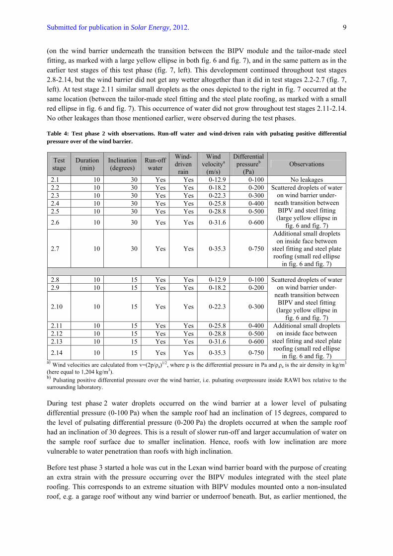
(on the wind barrier underneath the transition between the BIPV module and the tailor-made steel fitting, as marked with a large yellow ellipse in both fig. 6 and fig. 7), and in the same pattern as in the earlier test stages of this test phase (fig. 7, left). This development continued throughout test stages 2.8-2.14, but the wind barrier did not get any wetter altogether than it did in test stages 2.2-2.7 (fig. 7, left). At test stage 2.11 similar small droplets as the ones depicted to the right in fig. 7 occurred at the same location (between the tailor-made steel fitting and the steel plate roofing, as marked with a small red ellipse in fig. 6 and fig. 7). This occurrence of water did not grow throughout test stages 2.11-2.14. No other leakages than those mentioned earlier, were observed during the test phases.
Table 4: Test phase 2 with observations. Run-off water and wind-driven rain with pulsating positive differential pressure over of the wind barrier.
Test stage
Duration (min)
Inclination (degrees)
Run-off water
Wind-driven rain
Wind velocitya
(m/s)
Differential pressureb
(Pa) Observations
2.1 10 30 Yes Yes 0-12.9 0-100 No leakages 2.2 10 30 Yes Yes 0-18.2 0-200 2.3 10 30 Yes Yes 0-22.3 0-300 2.4 10 30 Yes Yes 0-25.8 0-400 2.5 10 30 Yes Yes 0-28.8 0-500
2.6 10 30 Yes Yes 0-31.6 0-600
Scattered droplets of water on wind barrier under-
neath transition between BIPV and steel fitting (large yellow ellipse in
fig. 6 and fig. 7)
2.7 10 30 Yes Yes 0-35.3 0-750
Additional small droplets on inside face between
steel fitting and steel plate roofing (small red ellipse
in fig. 6 and fig. 7)
2.8 10 15 Yes Yes 0-12.9 0-100 2.9 10 15 Yes Yes 0-18.2 0-200
2.10 10 15 Yes Yes 0-22.3 0-300
Scattered droplets of water on wind barrier under-
neath transition between BIPV and steel fitting (large yellow ellipse in
fig. 6 and fig. 7) 2.11 10 15 Yes Yes 0-25.8 0-400 2.12 10 15 Yes Yes 0-28.8 0-500 2.13 10 15 Yes Yes 0-31.6 0-600
2.14 10 15 Yes Yes 0-35.3 0-750
Additional small droplets on inside face between
steel fitting and steel plate roofing (small red ellipse
in fig. 6 and fig. 7) a) Wind velocities are calculated from v=(2p/ρa)1/2, where p is the differential pressure in Pa and ρa is the air density in kg/m3 (here equal to 1,204 kg/m3). b) Pulsating positive differential pressure over the wind barrier, i.e. pulsating overpressure inside RAWI box relative to the surrounding laboratory. During test phase 2 water droplets occurred on the wind barrier at a lower level of pulsating differential pressure (0-100 Pa) when the sample roof had an inclination of 15 degrees, compared to the level of pulsating differential pressure (0-200 Pa) the droplets occurred at when the sample roof had an inclination of 30 degrees. This is a result of slower run-off and larger accumulation of water on the sample roof surface due to smaller inclination. Hence, roofs with low inclination are more vulnerable to water penetration than roofs with high inclination.
Before test phase 3 started a hole was cut in the Lexan wind barrier board with the purpose of creating an extra strain with the pressure occurring over the BIPV modules integrated with the steel plate roofing. This corresponds to an extreme situation with BIPV modules mounted onto a non-insulated roof, e.g. a garage roof without any wind barrier or underroof beneath. But, as earlier mentioned, the

Submitted for publication in Solar Energy, 2012. 10
differential pressure levels which the test required could not be obtained inside the RAWI box due to the relatively air open steel plate roofing. Thus test phase 3 was terminated without results.
The differential pressures occurring over the BIPV sample roof in these laboratory investigations translates to the wind forces shown in table 5.
Table 5: The differential pressures occurring in the laboratory investigations and their corresponding wind velocities compared to the Beaufort wind force scale.
Differential pressure (Pa) 100 200 300 400 500 600 750
Wind velocity a (m/s) 12.9 18.2 22.3 25.8 28.8 31.6 35.3
Beaufort wind force scale
Strong breeze (6)
Fresh gale (8)
Strong gale (9)
Storm (10)
Violent storm (11)
Violent storm (11)
Hurricane force (12)
a Wind velocities are calculated from v=(2p/ρa)1/2, where p is the differential pressure in Pa and ρa is the air density in kg/m3 (here equal to 1,204 kg/m3). In these laboratory investigations the PV cells used in the BIPV modules were monocrystalline, thus it is very important to achieve a sufficient ventilation rate, as the solar cell efficiency is normally reduced with increasing temperature (Jelle and Breivik 2012a, Jelle and Breivik 2012b, Jelle et al. 2012, Wei et al. 2011). As depicted in fig. 8 the DuPont Gevity BIPV modules and the surrounding tailor-made steel fittings are constructed to obtain sufficient ventilation rates. The scattered water droplets which occurred on the wind barrier during testing (fig. 7, left) was transported with the airflow through the openings made in the tailor-made steel fittings for ventilation, as illustrated with blue arrows in fig. 8.
Fig. 8: Ventilation of the DuPont Gevity BIPV modules (DuPont 2010).
In order to prevent water penetration, the steel fittings surrounding the BIPV modules should ideally be better adapted to the BIPV modules, and the ventilation gaps should be constricted to some extent. This will, however, cause the ventilation rate to suffer, thus the degree of constriction must be evaluated in order to keep an acceptable ventilation rate. Moreover, the need for ventilation through these fittings depends on the roof construction beneath the BIPV modules, i.e. if the roof construction is well ventilated with an air gap between the underroof and the roofing, additional ventilation through these fittings (as illustrated with blue arrows in fig. 8) may not be necessary. Hence, if BIPV modules like the ones in question are mounted onto a roof construction with a well ventilated underroof, one can constrict the surrounding steel fittings to a greater extent, and obtain better rain tightness, without consideration for blocking the ventilation through these fittings.
The testing has demonstrated that the sample roof with the BIPV module system withstood the heavy wind-driven precipitation sufficiently. No leakages were detected in connection with the splices.
Submitted for publication in Solar Energy, 2012. 11
Nevertheless, different other leakage points were detected. A small quantity of penetrating water, such as detected during this investigation, will unlikely cause moisture problems for an adequately constructed and ventilated underroof (with an air gap between the underroof and the roofing). Thus, these leakages were not critical in terms of causing moisture problems for the roof construction, nevertheless they are still unwanted. However, if more severe leakages should occur, the water-resistance of the materials and the water tightness, drainage and drying-out capability of the underroof in question, determine whether it will lead to moisture problems in the roof construction or not.
In further studies, ideally four BIPV modules should be mounted together with the objective of testing both the vertical and the horizontal joint splices. This however, would require a rather large large-scale apparatus.
BIPVs are replacing part of the building envelope and hence have to fulfil requirements for various building physical properties (e.g. rain tightness, often wind tightness, heat and moisture transport, etc.) in addition to the solar cell properties (e.g. solar cell efficiency, open circuit voltage, short circuit electrical current, maximum power point, fill factor, quantum yield, etc.). Naturally, a long-term durability is desired for both PV and BIPV systems. As an example, if a BIPV system is water vapour tight (the PV area itself is vapour tight) - e.g. like a vapour barrier - then measures have to be taken in order to ensure no water vapour condensation or accumulation behind a vapour tight barrier. Shortly spoken, a PV only has to fulfil the requirements for the solar cell properties, while a BIPV in addition has to fulfil all the requirements for the building physical aspects for the actual building envelope part it is replacing.
In general, humidity and moisture may be or become an issue with regard to e.g. the drying-out capability of a building envelope incorporating a BIPV system, with respect to (a) the moisture diffusion transport driven by moisture pressure (or concentration) differences between the exterior and the interior climate (typical from the warm and moisture-rich interior towards the cold and less moisture-rich exterior), (b) any air leakages (also carrying moisture), and (c) any water penetrations e.g. from the ground, precipitation and wind-driven rain (roofs and walls). These and similar issues are dealt with by considering the building physics of a building, e.g. by performing the adequate building physics calculations, involving knowledge about both material properties and transport processes.
4. Conclusions In this study a sample roof with two BIPV modules went through large-scale testing with run-off water and wind-driven rain with incremental pulsating differential overpressure over the sample at two different inclinations (15 and 30 degrees). The BIPV sample roof was constructed as a real roof would have been constructed, with steel plate roofing, double furring strips and an airtight wind barrier beneath. The aim of this work was to illustrate challenges linked to the building envelope properties of a BIPV system, and to develop and evaluate relevant methods for testing the building envelope properties of BIPV systems. Hence, the purpose of these experimental investigations was to imitate real climate conditions, where a roof experiences pressure differences primarily over the wind barrier.
The laboratory investigations proved that the sample roof with the BIPV module system withstood the heavy wind-driven precipitation sufficiently. No leakages were detected in connection with the splices. Nevertheless, different other leakage points were detected, and although not influential, leakages are still unwanted. Depending on the water tightness of the underroof, small leakages like the ones detected in these laboratory investigations would unlikely lead to any moisture problems as long as the roof construction is adequately constructed and ventilated, i.e. with an underroof of sufficient water

Submitted for publication in Solar Energy, 2012. 12
tightness and water-resistant materials, and with drainage and drying-out capability. In order to prevent such water penetration, the tailor-made steel fittings surrounding the BIPV modules, which are made to allow a sufficient ventilation rate, should ideally be better adapted to the BIPV modules, and the ventilation gap constricted to some extent. However, the degree of constriction must be evaluated to keep an acceptable ventilation rate in order not to reduce the solar cell efficiency. The need for ventilation through these fittings depends on how well the roof construction beneath the BIPV modules is ventilated, i.e. additional ventilation through these fittings may not be necessary to obtain a sufficient ventilation rate if the roof construction is ventilated with an air gap between the underroof and the roofing. Hence, if BIPV modules are mounted onto a roof construction with a well ventilated underroof, one can, without consideration for blocking the ventilation through these fittings, constrict the surrounding steel fittings, and thus obtain enhanced rain tightness. In addition, this work demonstrates a suitable rain tightness test method for BIPV systems.
Acknowledgements This work has been supported by the Research Council of Norway and several partners through the NTNU and SINTEF research project ”The Research Centre on Zero Emission Buildings” (ZEB).
References B. Blocken and J. Carmeliet, “A review on wind-driven rain research in building science”, Journal of Wind Engineering and Industrial Aerodynamics, 92, 1079-1130, 2004.
B. Blocken and J. Carmeliet, “A simplified numerical model for rainwater runoff on building facades: Possibilities and limitations”, Building and Environment, 53, 59-73, 2012.
J. J. Bloem, “Evaluation of a PV-integrated building application in a well-controlled outdoor test environment”, Building and Environment, 43, 205-216, 2008.
A. J. Carr and T. L. Pryor, “A comparison of the performance of different PV module types in temperate climates”, Solar Energy, 76, 285-294, 2004.
A. N. Celik, “Long-term energy output estimation for photovoltaic energy systems using synthetic solar irradiation data”, Energy, 28, 479-493, 2003.
A. Chel, G. N. Tiwari and A. Chandra, “Simplified method of sizing and life cycle cost assessment of building integrated photovoltaic system”, Energy and Buildings, 41, 1172-1180, 2009.
R. Chenni, M. Makhlouf, T. Kerbache and A. Bouzid, “A detailed modeling method for photovoltaic cells”, Energy, 32, 1724-1730, 2007.
DuPont, “DuPont flashing systems – Physical properties data sheet”, 2008, http://www2.dupont.com/Tyvek_Weatherization/en_US/assets/downloads/K-16326_FlashingProdPropDataSheet.pdf (accessed March 26, 2012).
DuPont, “DuPont Gevity – Building integrated photovoltaics”, Unpublished work presented at ZEB-meeting (The Research Centre on Zero Emission Buildings), Trondheim, Norway, October, 2010.
P. Eiffert and G. Kiss, “Building integrated photovoltaic design for commercial and institutional structures”, NREL/BK-520-25272, 2000.

Submitted for publication in Solar Energy, 2012. 13
P. Eiffert, “Guidelines for the economic evaluation of building integrated photovoltaic power systems”, NREL/TP-550-31977, 2003.
H. J. Eldridge, “Common defects in buildings”, H. M. Stationery Off., London, 1976.
European Committee for Standardization, “Hygrothermal performance of building components and building elements - Determination of the resistance of external wall systems to driving rain under pulsating air pressure”, EN 12865:2001, European Committee for Standardization, Brussels, 2001.
S. Fasana and R. Nelva, “Improvement of the performance of traditional stone roofs by wind driven rain experimental tests”, Construction and Building Materials, 25, 1491-1502, 2011.
G. P. Hammond, H. A. Harajli, C. I. Jones and A. B. Winnett, “Whole systems appraisal of a UK building integrated photovoltaic (BIPV) system: energy, environmental, and economic evaluations”, Energy Policy, 40, 219-230, 2012.
R. A. Hazelwood, “Rain penetration mechanisms for lapped pitched roofs”, Chemistry and Industry, 16, 537-540, London, 1979.
Isola, “Isola Powertekk”, 2012, http://www.isola.no/produkter/tak/skratak/isola-powertekk/ (accessed March 26, 2012).
B. P. Jelle and C. Breivik, “State-of-the-art building integrated photovoltaics”, Energy Procedia, 20, 68-77, 2012a.
B. P. Jelle and C. Breivik, “The path to the building integrated photovoltaics of tomorrow”, Energy Procedia, 20, 78-87, 2012b.
B. P. Jelle, C. Breivik and H. D. Røkenes, “Building integrated photovoltaics: A state-of-the-art review and future research opportunities”, Solar Energy Materials and Solar Cells, 100, 69-96, 2012.
B. P. Jelle, ”Accelerated climate ageing of building materials, components and structures in the laboratory”, Journal of Materials Science, 47, 6475-6496, 2012.
J. C. Jol, B. J. M. van Kampen, B. J. de Boer, F. Reil and D. Geyer, “New test methods for BIPV: Results from IP performance”, Proceedings of 24th European Photovoltaic Solar Energy Conference and Exhibition, ECN Efficiency and Infrastructure, pp. 3925-3939, Hamburg, Germany, 21-25 September, 2009.
M. Mani, B. V. V. Reddy, M. Sreenath, S. Lokabhiraman and N. Anandrao, “Design of a climate-responsive BIPV research facility in Bangalore”, Proceedings of ISES Solar World Congress 2007: Solar Energy and Human Settlement, D. Y. Goswami and Y. Zhao (eds.), pp. 356-360, Springer, 2009.
M. Mattei, G. Notton, C. Cristofari, M. Muselli and P. Poggi, “Calculation of the polycrystalline PV module temperature using a simple method of energy balance”, Renewable Energy, 31, 553-567, 2006.
McKinsey and Company, “Pathways to a low-carbon economy. Version 2 of the global greenhouse gas abatement cost curve”, McKinsey and Company, 2009.
L. Mei, D. G. Infield, R. Gottschalg, D. L. Loveday, D. Davies and M. Berry, “Equilibrium thermal characteristics of a building integrated photovoltaic tiled roof”, Solar Energy, 83, 1893-1901, 2009.

Submitted for publication in Solar Energy, 2012. 14
Nordtest Method NT Build 421, “Roofs: Watertightness under pulsating air pressure”, Nordtest, Espoo, Finland, 1993.
B. Norton, P. C. Eames, T. K. Mallick, M. J. Huang, S. J. McCormack, J. D. Mondol and Y. G. Yohanis, “Enhancing the performance of building integrated photovoltaics”, Solar Energy, 83, 1629-1664, 2011.
T. E. Pedersen, N. Bakken and B. Time, “Regntetthet for kombinerte undertak og vindsperrer på rull (Rain tightness of combined underroofs and roll product wind barriers)”, SINTEF Building and Infrastructure, Project Report 23, 2008.
T. E. Pedersen, B. Time and E. M. Devold, “Kledning med trespon – eksperimentelle laboratorieundersøkelser og tidligere tiders erfaringer (Wooden chip cladding – experimental laboratory investigations and previous practices)”, SINTEF Building and Infrastructure, Project Report 47, 2009.
C. Peng, Y. Huang and Z. Wu, ”Building-integrated photovoltaics (BIPV) in architectural design in China”, Energy and Buildings, 43, 3592-3598, 2011.
E. W. Smiley, “Low irradiance performance modelling for building integrated photovoltaics”, in 17th European PV Solar Energy Conference, Munich, Germany, 2001.
S. Strong, “Building integrated photovoltaics (BIPV)”, Whole Building Design Guide, December 27, 2011, http://www.wbdg.org/resources/bipv.php (accessed March 29, 2012).
Swiss BiPV Competence Centre, “Energy from the sun”, 2010, http://www.bipv.ch/index.php?option=com_content&view=article&id=213&Itemid=3&lang=en (accessed April 19, 2012).
C. Wei, Z. Liu and X. Deng, “Application of thermoelectric generation technology in Building-integrated Photovoltaics (BIPV)”, Advanced Materials Research, 250-253, 2153-2156, 2011