large eddy simulation of airfoil self=noise · large eddy simulation of airfoil self-noise...
TRANSCRIPT

Large Eddy Simulation of Airfoil Self-Noise
Joseph G. Kocheemoolayil
Department of Aeronautics and Astronautics
Advisor: Sanjiva K. Lele
Department of Aeronautics and Astronautics and
Department of Mechanical Engineering
AMS Seminar Series, 02/09/2016

Introduction
Fig: Wolf et al., 2012
• Noise generated by a turbulent boundary layer thatencounters the trailing edge of an airfoil

Motivation
Google Images Oerlemans et al., 2007

The need for HPC
Oerlemans et al., 2007
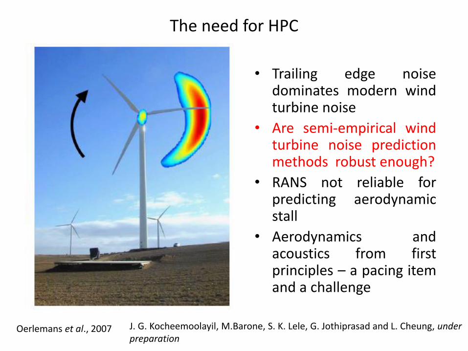
• Trailing edge noisedominates modern windturbine noise
• Are semi-empirical windturbine noise predictionmethods robust enough?
• RANS not reliable forpredicting aerodynamicstall
• Aerodynamics andacoustics from firstprinciples – a pacing itemand a challenge
J. G. Kocheemoolayil, M.Barone, S. K. Lele, G. Jothiprasad and L. Cheung, under preparation
The need for HPC
Oerlemans et al., 2007
• Trailing edge noisedominates modern windturbine noise
• Are semi-empirical windturbine noise predictionmethods robust enough?
• RANS not reliable forpredicting aerodynamicstall
• Aerodynamics andacoustics from firstprinciples – a pacing itemand a challenge
J. G. Kocheemoolayil, M.Barone, S. K. Lele, G. Jothiprasad and L. Cheung, under preparation

Engineering Models: BPM
LES: Wolf et al., 2012 Exp: Brooks et al., 1989, Devenport et al., 2010

Engineering Models: TNO
Exp: Devenport et al., 2010, Herr and Pott-Pollenske, 2011

The need for HPC
Oerlemans et al., 2007
• Trailing edge noisedominates modern windturbine noise
• Are semi-empirical windturbine noise predictionmethods robust enough?
• RANS not reliable forpredicting aerodynamicstall
• Aerodynamics andacoustics from firstprinciples – a pacing itemand a challenge
J. G. Kocheemoolayil, M.Barone, S. K. Lele, G. Jothiprasad and L. Cheung, under preparation
Numerical Simulation of Airfoil Self-Noise: Where are we?
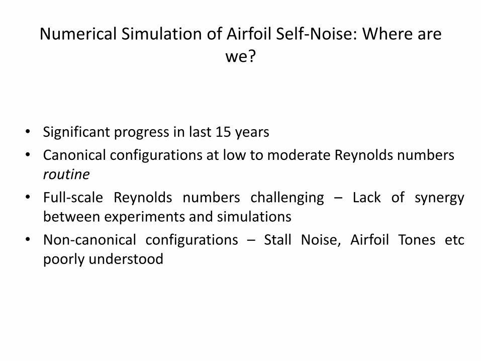
• Significant progress in last 15 years
• Canonical configurations at low to moderate Reynolds numbers routine
• Full-scale Reynolds numbers challenging – Lack of synergybetween experiments and simulations
• Non-canonical configurations – Stall Noise, Airfoil Tones etcpoorly understood

Numerical Simulation of Airfoil Self-Noise: Where are we?
• Significant progress in last 15 years
• Canonical configurations at low to moderate Reynolds numbers routine
• Full-scale Reynolds numbers challenging – Lack of synergybetween experiments and simulations
• Non-canonical configurations – Stall Noise, Airfoil Tones etcpoorly understood
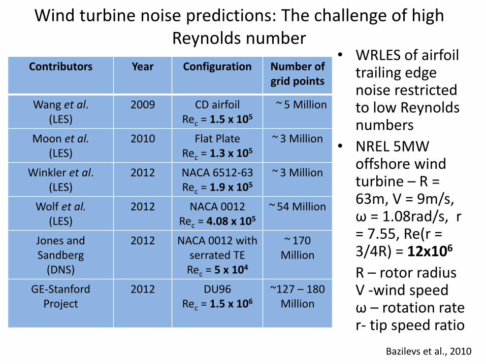
Wind turbine noise predictions: The challenge of high Reynolds number
Contributors Year Configuration Number of grid points
Wang et al. (LES)
2009 CD airfoilRec = 1.5 x 10⁵
~ 5 Million
Moon et al.(LES)
2010 Flat Plate Rec = 1.3 x 10⁵
~ 3 Million
Winkler et al. (LES)
2012 NACA 6512-63Rec = 1.9 x 10⁵
~ 3 Million
Wolf et al.(LES)
2012 NACA 0012Rec = 4.08 x 10⁵
~ 54 Million
Jones and Sandberg
(DNS)
2012 NACA 0012 with serrated TE
Rec = 5 x 10⁴
~ 170 Million
GE-Stanford Project
2012 DU96Rec = 1.5 x 10⁶
~127 – 180 Million
• WRLES of airfoil trailing edge noise restricted to low Reynolds numbers
• NREL 5MW offshore wind turbine – R = 63m, V = 9m/s, ω = 1.08rad/s, r = 7.55, Re(r = 3/4R) = 12x106
R – rotor radiusV -wind speed ω – rotation rate r- tip speed ratio
Bazilevs et al., 2010

LES of a wall bounded turbulent flow – The challenge of high Reynolds number
Choi and Moin, 2012Jimenez, 2012
• Scale disparity betweenproduction and dissipationexists only away from thewall
• Wall Resolved LES gridneeds to be very fine closeto a wall
• Consequence - Number of grid points (Ng) α Rex
13/7
• Wall Resolved LES isprohibitively expensive atlarge Reynolds numbers
Filled contours – co-spectra of tangential Reynoldsstress (production), Line contours – Spectra ofvorticity magnitude (surrogate for dissipation).Results from DNS of turbulent channel flow at afriction Reynolds number of 2000

Addressing the challenge of high Reynolds number
Choi and Moin, 2012
• The scale disparity between outer and innerscales responsible for Ng αRex
13/7
• Remedy - inner scales not resolved
• Effect on outer scales modeled using a stress boundary condition
• Outer eddies scale with the local boundary layer thickness – weak dependence on Rex
• Consequence - Number of grid points (Ng) α Rex
Pirozzoli and Bernardini, 2011
Instantaneous streamwise velocity from DNS of aturbulent boundary layer at y+ = 15. FrictionReynolds numbers (top to bottom) - 251, 497,1116

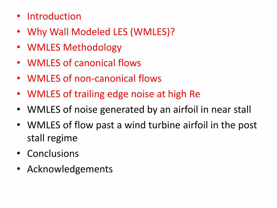
• Introduction
• Why Wall Modeled LES (WMLES)?
• WMLES Methodology
• WMLES of canonical flows
• WMLES of non-canonical flows
• WMLES of trailing edge noise at high Re
• WMLES of noise generated by an airfoil in near stall
• WMLES of flow past a wind turbine airfoil in the post stall regime
• Conclusions
• Acknowledgements

WMLES methodology
• Compressible or Weakly Compressible Navier-Stokes equations with constant coefficient Vreman sub-grid scale model on the LES grid
• Time-independent ODEs in wall normal direction based on the equilibrium assumption and an algebraic eddy viscosity model with wall damping for turbulence on the RANS grid
Fig: Bodart and Larsson, 2011

• Introduction
• Why Wall Modeled LES (WMLES)?
• WMLES Methodology
• WMLES of canonical flows
• WMLES of non-canonical flows
• WMLES of trailing edge noise at high Re
• WMLES of noise generated by an airfoil in near stall
• WMLES of flow past a wind turbine airfoil in the post stall regime
• Conclusions
• Acknowledgements

• Flow driven by a body force
• Periodic BCs in streamwise and spanwise directions
• Stress BC from wall model at the walls
• Results validated by comparison with DNS data
• Friction Reynolds number – 1440
WMLES of turbulent channel flow

WMLES of turbulent channel flow, Reτ ~ 1440, DNS ~ 500M points, WMLES ~ 1M points
WM matching location

• Introduction
• Why Wall Modeled LES (WMLES)?
• WMLES Methodology
• WMLES of canonical flows
• WMLES of non-canonical flows
• WMLES of trailing edge noise at high Re
• WMLES of noise generated by an airfoil in near stall
• WMLES of flow past a wind turbine airfoil in the post stall regime
• Conclusions
• Acknowledgements
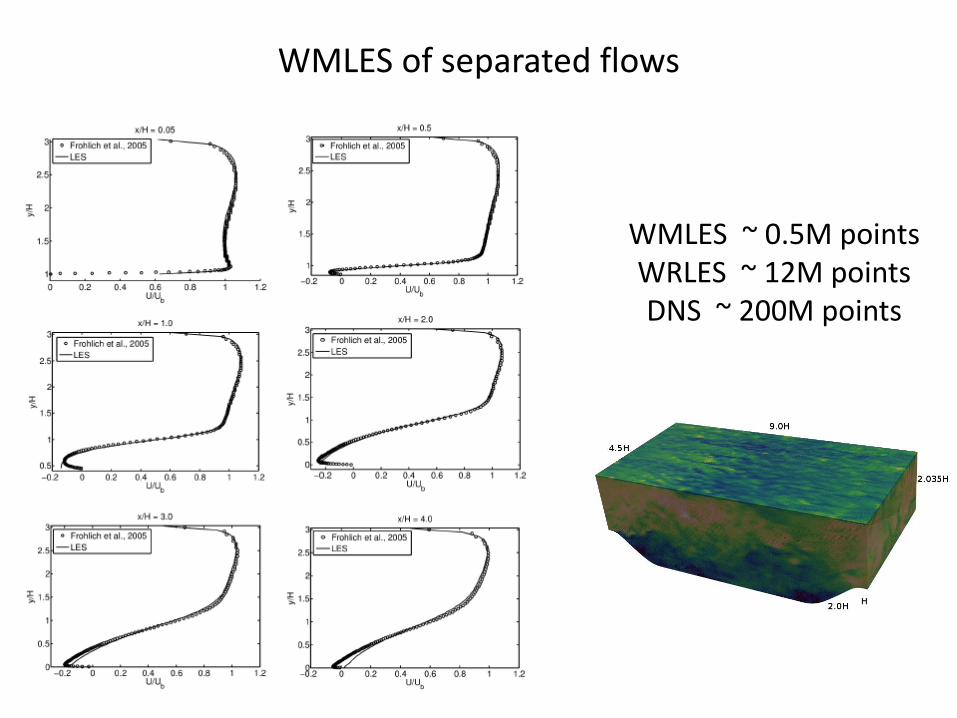
WMLES of separated flows
WMLES ~ 0.5M pointsWRLES ~ 12M pointsDNS ~ 200M points

“The NREL experiments have achieved significant new insight into wind turbineaerodynamics and revealed serious shortcomings in present-day wind turbineaerodynamics prediction tools. The Navier-Stokes computations generally exhibitedgood agreement with the measurements up to wind speeds of approximately 10ms−1.At this wind speed, flow separation sets in, and for higher wind speeds, the boundarylayer characteristics are dominated by stall and the computations under-predict thepower yield.”

Predicting wind turbine stall using WMLES

• Introduction
• Why Wall Modeled LES (WMLES)?
• WMLES Methodology
• WMLES of canonical flows
• WMLES of non-canonical flows
• WMLES of trailing edge noise at high Re
• WMLES of noise generated by an airfoil in near stall
• WMLES of flow past a wind turbine airfoil in the post stall regime
• Conclusions
• Acknowledgements

“Of particular interest in aeronauticaland naval applications is the predictivecapability of the method for surfacepressure fluctuations and noiseradiation. However, relative to the fullLES spectra, the spectral levels aresomewhat overpredicted, particularlyin the attached flow region [Figs.14(a)-14(c)]”
Over-prediction of fluctuating wall pressure and noise in WMLES

Over-prediction of turbulence intensity close to the wall
Townsend, 1976
• What does the stress BC do to the structure of attached eddies close to the wall?
• Stress BC from wall model does not constrain tangential components of fluctuating velocity to vanish at the wall
• Attached eddies slosh at the wall
Jimenez, 2012
Results from WMLES of turbulent flow in achannel at a friction Reynolds number of 1440.
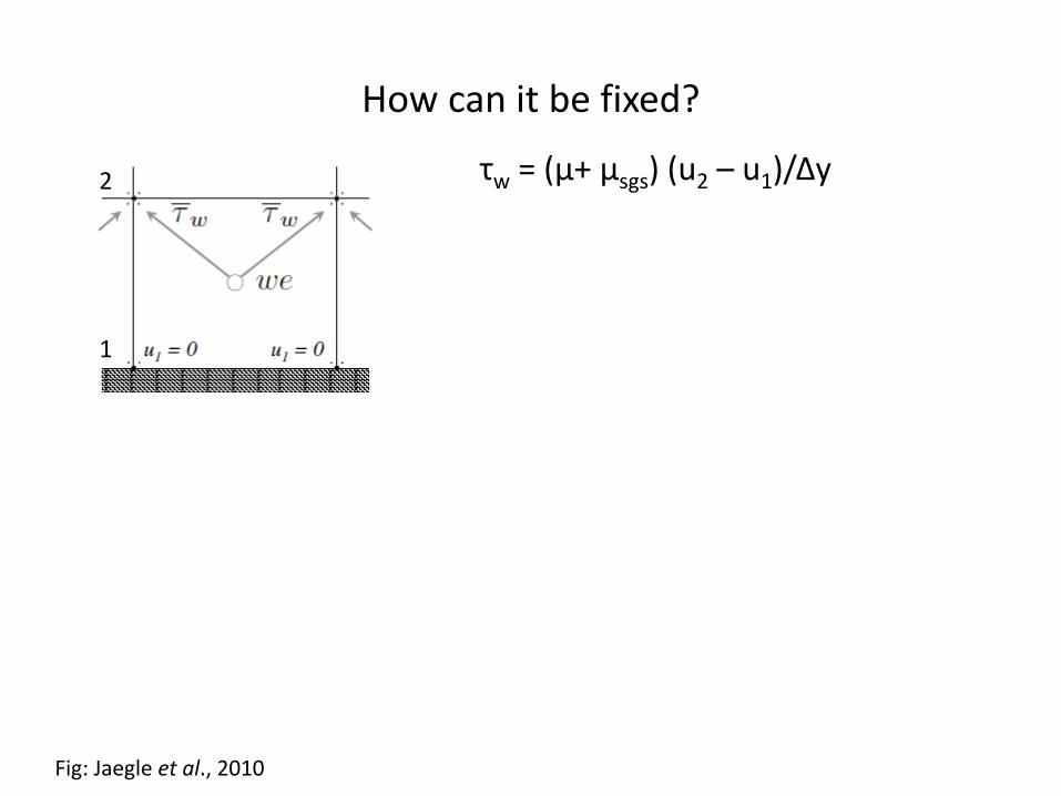
How can it be fixed?
Fig: Jaegle et al., 2010
τw = (μ+ μsgs) (u2 – u1)/Δy2
1
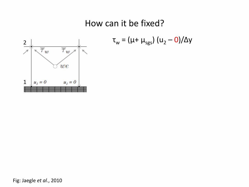
How can it be fixed?
Fig: Jaegle et al., 2010
τw = (μ+ μsgs) (u2 – 0)/Δy2
1

How can it be fixed?
Fig: Jaegle et al., 2010
τw = (μ+ μsgs) (u2 – 0)/Δy2
1
μt Augment μt to enforce the shear stress from the wall model

How can it be fixed?
Fig: Jaegle et al., 2010
τw = (μ+ μsgs) (u2 – 0)/Δy2
1
μt Augment μt to enforce the shear stress from the wall model
• No slip enforced at the wall
• Viscosity artificially augmented at the wall to enforce the shear stress from the wall model
• Does it improve prediction of fluctuating wall pressure? Yes
• Does it fix the issue altogether? Not quite

Budget of Poisson equation for fluctuating pressure
• Turbulence-mean shear interaction (Rapid) term over-predicted close to the wall
From WMLES of turbulent flow in a channel at afriction Reynolds number of 2000.

Budget of Poisson equation for fluctuating pressure
• Turbulence-mean shear interaction (Rapid) term over-predicted close to the wall
• Why?
From WMLES of turbulent flow in a channel at afriction Reynolds number of 2000.

Mean x-momentum balance
• Reynolds shear stress under-predicted close to the wall
• Subgrid scale model does not contribute enough (Not a RANS model)
• Flux from the wall sustained through a higher value of mean velocity gradient
From WMLES of turbulent flow in a channel at afriction Reynolds number of 2000.

Can the error be fixed? How does it respond to grid refinement?
• To solve the issue, numerical and subgrid scale model errors atthe first few off-wall points need to be addressed – Even aperfect wall stress model won’t suffice
• A posteriori correction possible, but not practical
• The over-prediction reduces on finer grids as the Reynolds shearstress starts contributes more to the momentum balance in thevicinity of the wall
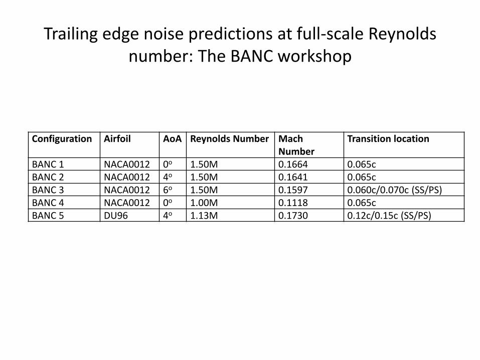
Trailing edge noise predictions at full-scale Reynolds number: The BANC workshop
Configuration Airfoil AoA Reynolds Number Mach Number
Transition location
BANC 1 NACA0012 0o 1.50M 0.1664 0.065cBANC 2 NACA0012 4o 1.50M 0.1641 0.065cBANC 3 NACA0012 6o 1.50M 0.1597 0.060c/0.070c (SS/PS)BANC 4 NACA0012 0o 1.00M 0.1118 0.065cBANC 5 DU96 4o 1.13M 0.1730 0.12c/0.15c (SS/PS)
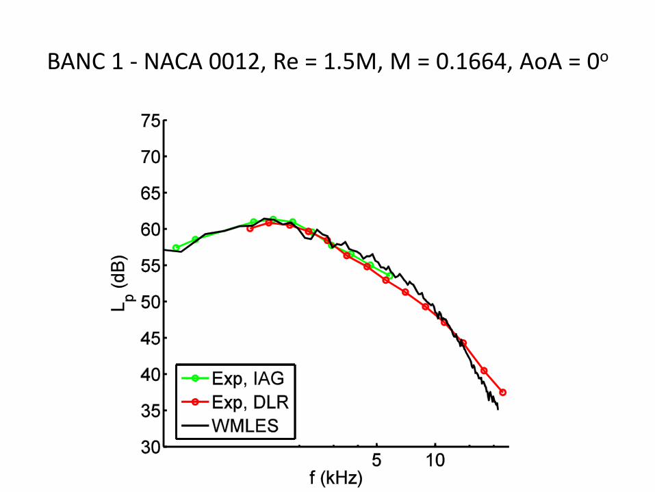
BANC 1 - NACA 0012, Re = 1.5M, M = 0.1664, AoA = 0o

Interpreting the far-field noise spectrum
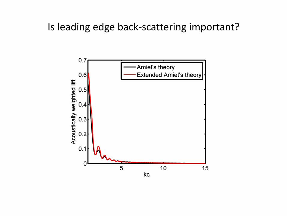
Is leading edge back-scattering important?

Is leading edge back-scattering important?

Comparison of near wake flow-field to measurements

Sensitivity to grid resolution

Trailing edge noise predictions at full-scale Reynolds number: The BANC workshop
Configuration Airfoil AoA Reynolds Number Mach Number
Transition location
BANC 1 NACA0012 0o 1.50M 0.1664 0.065cBANC 2 NACA0012 4o 1.50M 0.1641 0.065cBANC 3 NACA0012 6o 1.50M 0.1597 0.060c/0.070c (SS/PS)BANC 4 NACA0012 0o 1.00M 0.1118 0.065cBANC 5 DU96 4o 1.13M 0.1730 0.12c/0.15c (SS/PS)

BANC 3 - NACA 0012, Re = 1.5M, M = 0.1597, AoA = 6o

The effect of loading
• Introduction
• Why Wall Modeled LES (WMLES)?
• WMLES Methodology
• WMLES of canonical flows
• WMLES of non-canonical flows
• WMLES of trailing edge noise at high Re
• WMLES of noise generated by an airfoil in near stall
• WMLES of flow past a wind turbine airfoil in the post stall regime
• Conclusions
• Acknowledgements
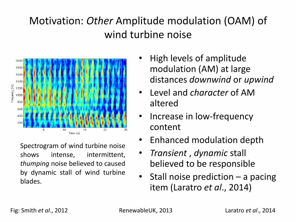
Motivation: Other Amplitude modulation (OAM) of wind turbine noise
• High levels of amplitude modulation (AM) at large distances downwind or upwind
• Level and character of AM altered
• Increase in low-frequency content
• Enhanced modulation depth
• Transient , dynamic stall believed to be responsible
• Stall noise prediction – a pacing item (Laratro et al., 2014)
Fig: Smith et al., 2012
Spectrogram of wind turbine noiseshows intense, intermittent,thumping noise believed to causedby dynamic stall of wind turbineblades.
RenewableUK, 2013 Laratro et al., 2014

What happens to fluctuating wall pressure at higher AoA?

Noise generated by an airfoil in near stall configuration – NACA 0012, Re = 1.5M, M = 0.16, AoA = 10o

• Introduction
• Why Wall Modeled LES (WMLES)?
• WMLES Methodology
• WMLES of canonical flows
• WMLES of non-canonical flows
• WMLES of trailing edge noise at high Re
• WMLES of noise generated by an airfoil in near stall
• WMLES of flow past a wind turbine airfoil in the post stall regime
• Conclusions
• Acknowledgements

WMLES of turbulent flow past a DU96 airfoil in stall
• Configuration – DU96-W-180 airfoil at an angle ofattack of 13.2 degrees, chord based Reynoldsnumber of 1.5M
• Comparisons made with experiments from DelftUniversity (Courtesy: Dr. N. Timmer)

Flow Visualization: Contours of streamwise velocity (Negative values intentionally saturated to visualize reverse flow regions
better)
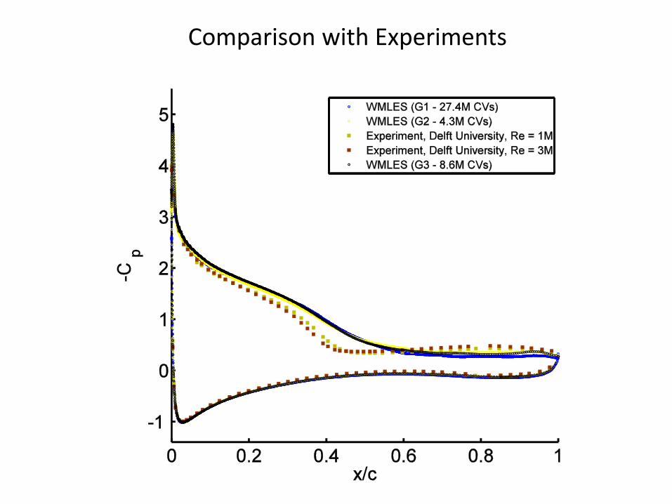
Comparison with Experiments
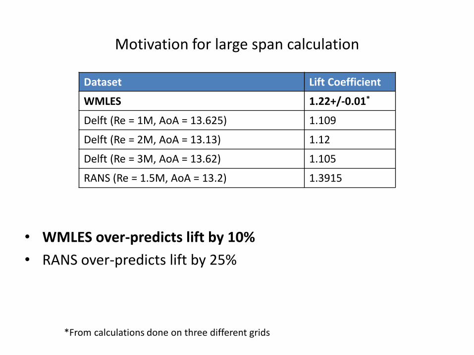
Motivation for large span calculation
Dataset Lift Coefficient
WMLES 1.22+/-0.01*
Delft (Re = 1M, AoA = 13.625) 1.109
Delft (Re = 2M, AoA = 13.13) 1.12
Delft (Re = 3M, AoA = 13.62) 1.105
RANS (Re = 1.5M, AoA = 13.2) 1.3915
*From calculations done on three different grids
• WMLES over-predicts lift by 10%
• RANS over-predicts lift by 25%
Figs: F. Menter, private communication and Schewe, 2001
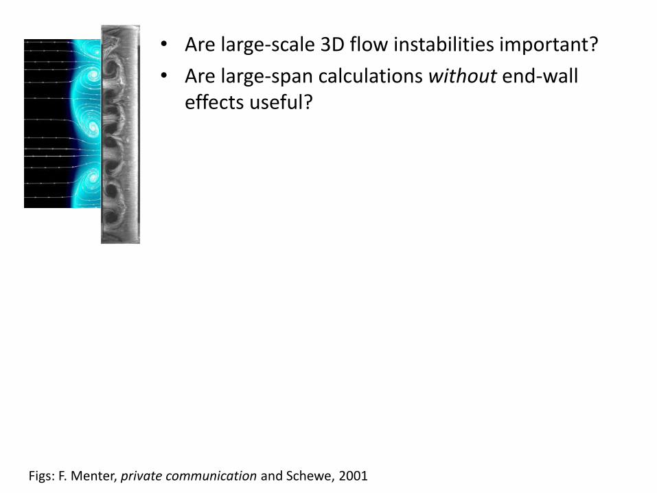
• Are large-scale 3D flow instabilities important?
• Are large-span calculations without end-wall effects useful?

Figs: F. Menter, private communication and Schewe, 2001
• Are large-scale 3D flow instabilities important?
• Are large-span calculations without end-wall effects useful?
• Yes – Stall cells affected by end-walls, but notcaused by it (cf. Spalart (2014))
Figs: F. Menter, private communication and Schewe, 2001
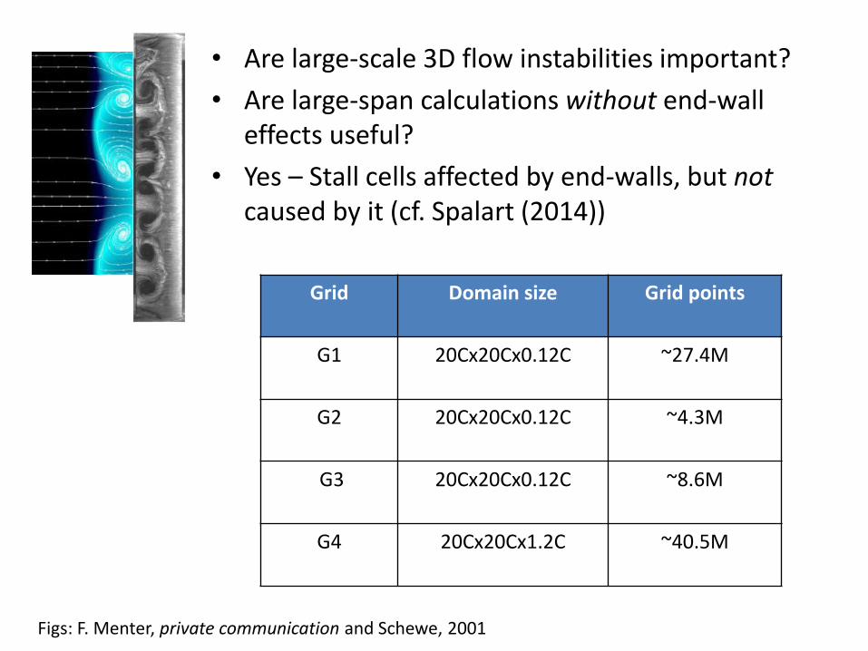
• Are large-scale 3D flow instabilities important?
• Are large-span calculations without end-wall effects useful?
• Yes – Stall cells affected by end-walls, but notcaused by it (cf. Spalart (2014))
Grid Domain size Grid points
G1 20Cx20Cx0.12C ~27.4M
G2 20Cx20Cx0.12C ~4.3M
G3 20Cx20Cx0.12C ~8.6M
G4 20Cx20Cx1.2C ~40.5M

Figs: F. Menter, private communication and Schewe, 2001
• Are large-scale 3D flow instabilities important?
• Are large-span calculations without end-wall effects useful?
• Yes – Stall cells affected by end-walls, but notcaused by it (cf. Spalart (2014))
Grid Domain size Grid points
G1 20Cx20Cx0.12C ~27.4M
G2 20Cx20Cx0.12C ~4.3M
G3 20Cx20Cx0.12C ~8.6M
G4 20Cx20Cx1.2C ~40.5M

Stall Cells

Large-scale 3D flow instability

Comparison with Experiments
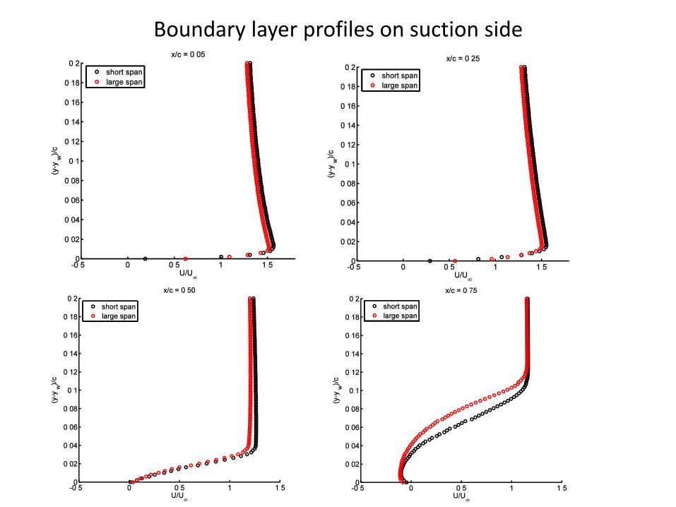
Boundary layer profiles on suction side
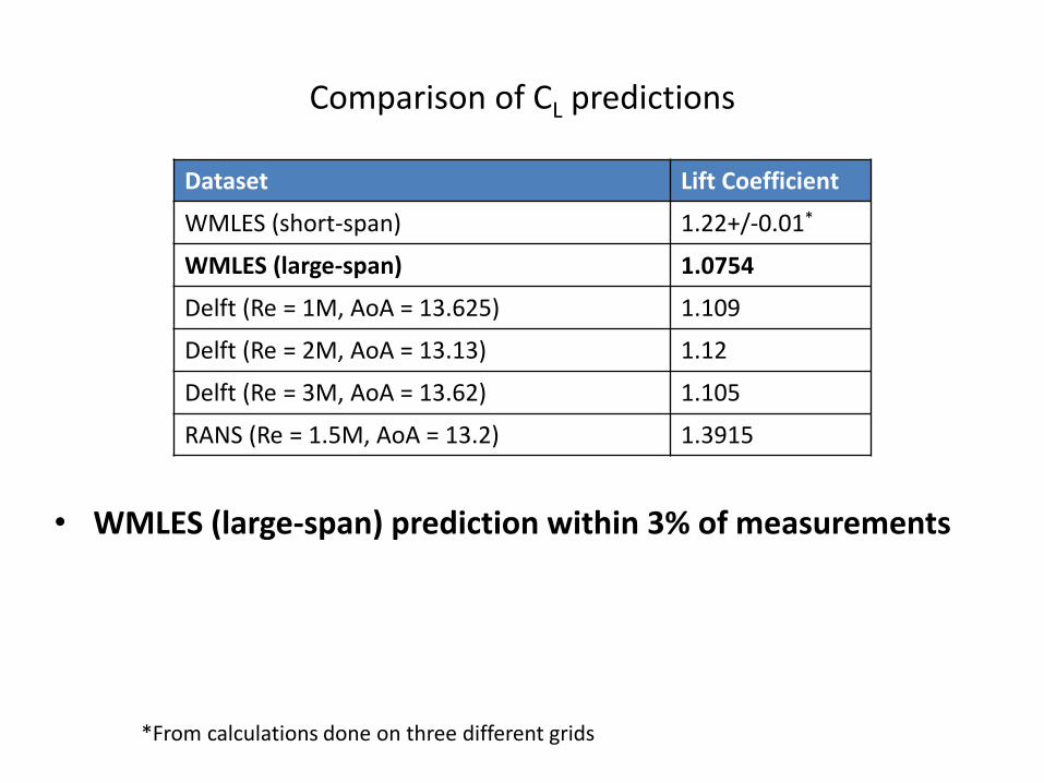
Comparison of CL predictions
Dataset Lift Coefficient
WMLES (short-span) 1.22+/-0.01*
WMLES (large-span) 1.0754
Delft (Re = 1M, AoA = 13.625) 1.109
Delft (Re = 2M, AoA = 13.13) 1.12
Delft (Re = 3M, AoA = 13.62) 1.105
RANS (Re = 1.5M, AoA = 13.2) 1.3915
*From calculations done on three different grids
• WMLES (large-span) prediction within 3% of measurements

• Introduction
• Why Wall Modeled LES (WMLES)?
• WMLES Methodology
• WMLES of canonical flows
• WMLES of non-canonical flows
• WMLES of trailing edge noise at high Re
• WMLES of noise generated by an airfoil in near stall
• WMLES of flow past a wind turbine airfoil in the post stall regime
• Conclusions
• Acknowledgements

Conclusions
• First successful prediction of trailing edge noise from firstprinciples at full scale Reynolds numbers
• Successful prediction of noise generated by an airfoil in the near stall regime
• Aerodynamic stall of a wind turbine airfoil at full-scale Reynoldsnumbers using WMLES – Novel large span calculation showsevidence for stall cells
• Introduction
• Why Wall Modeled LES (WMLES)?
• WMLES Methodology
• WMLES of canonical flows
• WMLES of non-canonical flows
• WMLES of trailing edge noise at high Re
• WMLES of noise generated by an airfoil in near stall
• WMLES of flow past a wind turbine airfoil in the post stall regime
• Other contributions – Airfoil Tones
• Conclusions
• Acknowledgements

Acknowledgements

Flow Simulation
• Node-based finite volume scheme
• Implicit time advancement
• Second-order accurate in space and time
• Minimally dissipative – relies on discrete kinetic energy conservation for numerical stability
• Low-Mach, weakly compressible formulation
• High-frequency acoustic waves filtered out, low frequency acoustic waves retained
• Vreman model for subgrid scales of turbulence
• BCs – stress BC from wall model on the airfoil surface, Sponge BC at far-field boundaries to minimize spurious reflections
• Steady suction/blowing to force transition to turbulence

Far-field noise prediction
• Ffowcs Williams Hawkings Equation
• Amiet’s theory, Extended Amiet’s theory with leading edge back-scattering corrections from Roger and Moreau
• Chase-Chandiramani-Howe diffraction theory
• Finite-chord and finite-thickness effects investigated
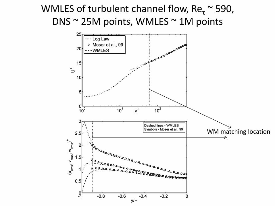
WMLES of turbulent channel flow, Reτ ~ 590, DNS ~ 25M points, WMLES ~ 1M points
WM matching location