large challenges of a small project dave logan, p.e
TRANSCRIPT

1
Large Challenges of a Small Project
Dave Logan, P.E.1
1POWER Engineers Incorporated, 3 Centerpointe Drive, Suite 500, Portland Oregon, 97035; email: [email protected] INTRODUCTION Minnesota Power’s North Shore Switching Station 115kV Transmission Line Project in Northern Minnesota, along the North Shore of Lake Superior, consists of three-quarters of a mile of new double-circuit transmission line. The project connects the new North Shore Switching Station to the existing Silver Bay Substation. The project was wholly within an active iron ore processing plant property, so the site was constrained by various plant, road and material transport systems that did not leave much room for new linear facilities. The purpose of this paper is to explore in detail the design and construction challenges faced during scope development and implementation of the project, and how the design team addressed those challenges. DESIGN CHALLENGES The design team faced numerous challenges with this short transmission line including:
• History of heavy ice • Potential for conductor galloping • Heavy insulator contamination • Diverse subsurface conditions • Clearance over plant pipe bridges • Higher than normal ground clearance requirements • Project-specific, special clearance zones • Non-standard materials
Design Criteria The first challenge facing the team was developing a design criteria document to address the numerous challenges of the project. Minnesota Power has a very robust standard design criteria already developed, but it was only a starting point as many of the challenges from the North Shore project were not typical.
Structure Type The North Shore tie lines run directly through an active iron ore processing facility that runs all hours of every day except for small planned outages for maintenance and repair. Large mining equipment operates continuously throughout the facility meaning that structure footprint and location were key considerations in the design. The existing 42L and 128L lines are supported primarily on lattice and wood H-frame structures. However, the restrictive right-of-way prevented the use of multi-legged structures. Double circuit steel monopole structures on concrete foundations were selected to minimize structure footprint and quantity, avoid interfering with the activities at the

2
facility and allow structures to be placed in a location mostly out of the way of vehicle traffic. Foundation Type Exposed rock was visible throughout the project alignment. Because of the potential for variable subsurface conditions at each structure location, geotechnical investigations were performed for each structure. The variation in subsurface conditions meant that multiple foundation types had to be considered with no single solution being appropriate at all locations. Drilled piers were the desired foundation type, but micropiles and rock anchor foundations were considered for areas of shallow rock. Weather Criteria and Load Cases Line 42L out of Silver Bay substation has experienced severe ice and wind loading during its life. Minnesota Power typical loading criteria includes considerations for NESC 250B, 250C, and 250D loading cases, along with some additional severe weather conditions to try to account for extreme events that are possible in its service territory. The project-specific heavy wind and ice case was set at 50 mph wind with 1.5 inches of radial ice. A 110 mph extreme case was also used in design because of the potential of high winds blowing off nearby Lake Superior.
The design team was comfortable with the final loading used in design because it was something a bit more conservative than the provision of NESC without trying to design to the absolute worst-case event. The final design of the structures will support most conditions throughout the life of the line and avoid any catastrophic failure during extreme, uncommon weather events. Conductor Motion The project proximity to the lake provided textbook conditions for galloping. To add to the challenge, span lengths were long, but not quite long enough to justify double-loop galloping, so single-loop analysis was used to determine galloping ellipses. The NESC does not provide specific values for clearance between wires of the same circuit, so the recommendations of RUS Bulletin 1724E-200 are typically used for designing phase clearance. However, under a galloping event vertical phase spacing would have to be very large to maintain RUS clearances, so the final galloping criteria was limited to avoiding clashing of wires during a galloping event. Insulation Insulator contamination levels on the North Shore project site were categorized as “heavy” to “very heavy” for design of insulation. This resulted in the need for larger levels of insulation than the Minnesota Power standard design for a 115kV line.
Conductor Selection The original project planning developed by Minnesota Power identified 795 kcmil ACSR 45/7 “Tern” for the north circuit and 636 kcmil ACSR 24/7 “Rook” for the south circuit. The wire selected was based on required electrical loading and common conductor types in Minnesota Power’s system. Using common conductor helps ensure availability of materials for maintenance

3
or storm restoration issues that may arise. As design progressed, additional tension was needed to address clearance and galloping issues. The design tensions for Tern and Rook for this project were 6,630 lbs. and 6,780 lbs. under NESC 250B, respectively. These relatively lower tensions were advantageous from a structural loading perspective, but caused concern from a sag and clearance perspective. The increased sag in the conductors caused an increase in structure heights, as well as increased phase spacing to avoid clashing under galloping conditions. To remediate these concerns, the design team considered the use of interphase spacers as well as a change in the conductor.
Interphase Spacers The design team considered four different vendor products. Two products raised concerns because of a lack of test results available. The interphase spacers from these two vendors are essentially re-purposed polymer insulators connected by a yoke plate. Individual components were tested for their original purpose, but the system of components had not been thoroughly tested as an interphase spacer and there was a lack of field experience with these products.
The other two products were rigid connection interphase spacers (Fig. 1) designed specifically for that purpose. However, one of the vendors offered no testing and a rather limited warranty, while the other performed significant levels of testing to confirm durability of their product and provided an extensive warranty. The product with the longer record of testing and longer warranty was pursued by the design team with conversations taking place over several months. After early coordination with the vendor, doubts arose about delivery schedule meeting project requirements and it was decided to discontinue procurement efforts and the use of interphase spacers was abandoned on the project.
Final Conductor Selection Following the decision to move away from interphase spacers, the design team revisited the conductor selection for this project. The original conductors were selected based on operational loading and availability. The combination of span lengths and loading conditions resulted in a large amount of sag in the Rook and Tern conductors, which exacerbated the galloping concern. Although sufficient to handle electrical loading for the two circuits, the rather low RBS limited the stringing tension for the conductors.
Fig. 1 – Interphase Spacer

4
795 kcmil ACSR “Drake” satisfied the electrical loading capacity required by both circuits, but with an RBS of 31,500 lbs. vs the 22,100 lbs. and 22,600 lbs. RBS for the Tern and Rook (respectively), the Drake conductor could be strung to a higher installed tension. This significantly reduced the sag in the wire. Pole top configuration was modified to a double circuit delta configuration (Fig. 2). That configuration, combined with the lower sag of the new conductor, reduced the davit arm spacing and lowered overall structure heights.
Structures Several factors contributed to a challenging structure design. Although the ultimate structure type and configuration are not particularly unique, conditions of the project resulted in structures that were taller and heavier than is typical for a line of this voltage.
Structure Height The potential for line galloping increased structure height because of the greater required vertical phase spacing to avoid clashing of wires. More significantly, clearance to ground and overhead objects increased the structure heights.
Equipment Clearances Typical equipment at the facility included front loaders and dump trucks with vehicle heights as much as 25 feet. To accommodate vehicles of this size, the minimum clearance to ground for all mine property was set to 33 feet.
Pipe Bridges The line crossed over pipe bridges (Fig. 3). The bridges were tall enough to maintain reasonable clearance to the large equipment and rail cars that frequent the property and are accessible to workers for maintenance purposes. Because the bridges were accessible, clearance to them for new design was 19.5 feet. Because of the height of the pipe bridges and required clearance to the bridges, conductor height crossing over them was as much as 60 feet above ground.
Fig. 2 – Pole Top Configuration
Fig. 3 – Pipe Bridge
5
Switching Station Expansion The northern side of the new North Shore switching station was planned for future expansion underneath the line. However, the plans for this expansion had not been finalized, so equipment size was unknown and precise clearance requirements were not available. A special 55-foot clearance to ground zone was applied to the switching station expansion to allow for foreseeable equipment configuration in the future. The first structure outside the north end of the station had to be even taller to accommodate the increase sag because of the limited tension capacity of the switching station structure.
Structure Material The change in conductor resulted in higher ultimate tensions in the line. This, combined with the excess height of the structures, resulted in heavier pole shafts and thicker base plates than expected. Many poles had such extreme forces that flanged rather than slip joints were required. Minnesota Power standard specification for steel poles calls for normalizing and tempering of base and flange plate material. The extreme cold can reduce the ductility of the steel causing brittle failure. Normalizing and tempering the material helps to decrease hardness (brittleness), internal stresses and strains, and promotes uniformity in the grains to help improve the notch toughness of the steel. This type of material must be coordinated with the mill which typically has a long lead time. Insulator Selection Because of the heavy contamination levels encountered on the project site, insulators with hydrophobic properties were ideal to help reduce frequency of insulator wash cycles. However, Minnesota Power has moved away from using polymer insulators because of a history of poor field performance in their system. This project consisted of only nine structures in total. RTV silicone coated toughened glass insulators were considered but ultimately abandoned because of the limited quantity needed. Minnesota Power does not have coated glass insulators anywhere else in its system, meaning it does not regularly stock them. Using these insulators on the North Shore project would require the purchase and storage of a niche material for a very small line in their system. Ultimately, the heavy contamination levels were addressed in the final design by increasing the number of non-coated toughened glass insulator bells to the insulator strings. The increase in the overall length of the insulator string improved leakage and flashover performance, but required modification to running angle structure designs to maintain clearance to pole under blowout conditions.

6
High Traffic Location No documentation was available to determine the strength capacity of the existing lattice structures of 42L in the first several spans outside of Silver Bay substation. A large amount of time and effort would be necessary to collect information, model and analyze the existing structures. Rather than risk modifications that could result in overstressing the existing lattice structures, it was decided to place the tap structure (STR 617 in Fig. 4) in between the substation and the first structure, which was a low-tension slack span into the station. The location for the tap structure presented several issues, specifically related to vehicle traffic. With limited space, the tap structure would have to be placed at the edge of an active roadway at the base of a downslope. Large mining equipment regularly travels past the structure location, exposing the structure to a high risk of vehicle impact. Several measures were taken to mitigate the potential for damage to the structure: • The pedestal portion of the micropile cap was increased to a 10-foot diameter and
extended to 6 feet of reveal. The pedestal also was formed using steel casing, which was left in place for added protection.
• During restoration of the roadway after structure installation, the road alignment was modified to direct traffic away from the structure.
• Jersey barriers originally installed for protection and traffic diversion during construction were permanently installed at the edge of the new roadway alignment and were painted with high visibility yellow.
Foundations The North Shore project site had several areas of shallow, high rock-quality designation rock. Minnesota Power typically relies on traditional drilled pier construction for steel pole foundations. However, rock was encountered as little as 4 feet below grade in the geotechnical investigation, and the rock was hard enough that drilling piers or rock sockets into the rock could greatly extend the installation time.
Fig. 4 – Foundation at STR 617

7
Drilled Pier Alternative A foundation contractor was brought on for support during foundation design to aid in foundation type selection. Micropiles were selected as the preferred alternative to drilled pier. Following structure design, each location was reviewed for suitability of a drilled pier foundation. Locations where drilled pier foundations could be supported in the soil above the rock, or where one full pier diameter long rock socket was sufficient, drilled piers were selected except where access was an issue. At all other locations, micropile foundations were used (Fig. 5). Anchor Bolts Initial foundation type was assumed to be drilled pier foundations. This allowed for smaller bolt circles and fewer anchor bolts than shallower foundation options, which aided in limiting structure footprint. However, as it became more apparent that drilled pier foundations could not be used at all locations, the drilled pier assumption became an issue. The cold joint between the pad and pedestal breaks the development length, meaning that all the bolt strength development had to occur in the pad only. To meet procurement deadlines, anchor bolt design and fabrication was complete prior to final foundation type determination. The original anchor bolt design was based on 3,000 psi concrete. With help from the pole vendor, required development length was reduced by specifying higher strength concrete for construction. Additionally, the vendor was able to design embed plates to attach to the bottom of the anchor bolt cage to further reduce required development length.
CONSTRUCTION CHALLENGES Line Construction Because of the span lengths, AGS units were selected for tangent suspension insulator wire attachment to prevent damage to the conductor. The hardware specified was compatible with ANSI 52-5 ball-and-socket hardware. However, much of the material for the project had been specified prior to the final decision to coordinate insulators with the Great Northern project, which used larger capacity suspension insulators having ANSI 52-8 ball-and-socket connection.
Fig. 5 – Micropile Drill Rig
8
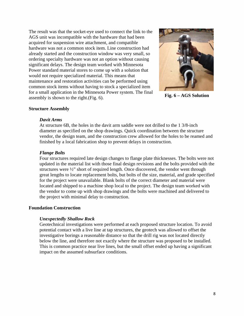
The result was that the socket-eye used to connect the link to the AGS unit was incompatible with the hardware that had been acquired for suspension wire attachment, and compatible hardware was not a common stock item. Line construction had already started and the construction window was very small, so ordering specialty hardware was not an option without causing significant delays. The design team worked with Minnesota Power standard material stores to come up with a solution that would not require specialized material. This means that maintenance and restoration activities can be performed using common stock items without having to stock a specialized item for a small application in the Minnesota Power system. The final assembly is shown to the right.(Fig. 6). Structure Assembly
Davit Arms At structure 6B, the holes in the davit arm saddle were not drilled to the 1 3/8-inch diameter as specified on the shop drawings. Quick coordination between the structure vendor, the design team, and the construction crew allowed for the holes to be reamed and finished by a local fabrication shop to prevent delays in construction. Flange Bolts Four structures required late design changes to flange plate thicknesses. The bolts were not updated in the material list with those final design revisions and the bolts provided with the structures were ½” short of required length. Once discovered, the vendor went through great lengths to locate replacement bolts, but bolts of the size, material, and grade specified for the project were unavailable. Blank bolts of the correct diameter and material were located and shipped to a machine shop local to the project. The design team worked with the vendor to come up with shop drawings and the bolts were machined and delivered to the project with minimal delay to construction.
Foundation Construction
Unexpectedly Shallow Rock Geotechnical investigations were performed at each proposed structure location. To avoid potential contact with a live line at tap structures, the geotech was allowed to offset the investigative borings a reasonable distance so that the drill rig was not located directly below the line, and therefore not exactly where the structure was proposed to be installed. This is common practice near live lines, but the small offset ended up having a significant impact on the assumed subsurface conditions.
Fig. 6 – AGS Solution

9
Subsurface conditions at the project site varied greatly. The boring taken for STR 617 indicated rock at 9 feet below grade (Fig. 8). The micropile foundation was designed to ensure that the pad of the pile cap was fully below grade. This was critical at this location as the structure was already impinging on the roadway. When the excavation began at this location, the contractor encountered bedrock immediately below the pavement. A large amount of rock had to be removed to accommodate the pad below grade. The disparity between the installed pile cap elevation and the top of rock elevation was as much as 4 feet.
The micropile drill rig was used to drill a series of holes in the rock to allow the rock to be hammered out and a larger excavator had to be brought in to remove the rock. Overall, the unexpected rock caused several days of delay in the installation of micropiles at STR 617, however, the contractor was able to move up some activities at other locations so the crews were not left idle, and the critical foundation work was completed on schedule despite the delay at the first structure.
Underground Facilities Although underground investigations and utility locates were performed prior to final design and construction, structure locations for preliminary design used for geotechnical planning were based on incomplete records and limited knowledge of underground facilities. After final utility and underground facility locates were performed, conflicts were identified which required relocation of several structures.
Stepped Foundation Structure 619 was originally spotted within 10 feet of an underground wash water reclamation channel. Structure 619 was moved ahead online toward structure 620, away from the channel to reduce the influence of the foundation on the underground structure and to prevent the risk of damage to the channel during construction. To even out spans and to level the grade of the line, 620 was also moved ahead on line. The result of moving 620 was that rock was encountered before the full depth of the drilled pier could be reached. The high RQD basalt proved to be extremely difficult to drill. Stepped casing had been used because of the unstable fill above the rock, so the foundation was evaluated by the design engineer as a stepped foundation based on the casing sizes used. The contractor was allowed to stop drilling into the rock and pour the foundation shorter than originally designed, given the additional requirement of backfilling around the top of the pier with well-graded, compacted structure backfill to limit pile-head deflection.
Fig. 8 – Shallow Rock at STR 617

10
Gas Line and Boulders Structure 6A was originally spotted at the base of a hill. At some time in the past, large boulders had been pushed down the hill and now reside where structure 6A was originally spotted (Fig. 9). The boulders in question were roughly the size of a pickup. The mass of the boulders was not obvious in the LiDAR or aerial imagery. To complicate the issue, a 2-inch PVC natural gas line was located fairly close to structure 6A. Moving the boulders introduced risk of accidentally crushing the gas line. Instead of risking damage to the gas line and delay to mobilize additional equipment, 6A was moved to the southeast. This relocation placed the structure closer to the gas line. The micropile cap was raised so the pile cap loading on the soil would not affect the gas line. The contractor installed temporary sheet piling between the foundation excavation and the gas line to prevent damage to the line during construction.
Concrete Pouring and Testing Several different mix designs were required for foundations on this project. Drilled pier foundations were specified as 4,000 psi with 5-inch slump, while micropile caps were specified as 5,000 psi with a 6- to 7-inch slump. Micropile grout was specified as high early strength of 5,000 psi at three-day break to allow for earlier testing of grouted piles.
Unexpected Low Grout Strength With this variety of mixes, sampling and testing was of utmost importance. The micropile testing schedule required early high strength to prevent delays in pile cap construction. However, unexpectedly low early values on grout caused concern with early testing of grouted piles. The design team worked with the contractor and the testing company to determine the best course of action. Delay in pile testing would have a cascading effect, so it was decided to break additional samples early. Review of the additional early breaks indicated that previous samples were not particularly representative of actual grout strength. The contractor was cleared to proceed with early testing of the micropiles as schedule, and all passed the specified foundation performance criteria. Mass Concrete The size of the micropile caps required implementation of mass concrete protocol as defined in ACI 318. Differential temperatures in mass concrete structures can cause significant cracking, exposing the concrete and rebar to corrosive attacks. Delayed ettringite formation (DEF) occurs when the internal temperature gets too high resulting in an internal sulfur attack causing swelling and internal damage to the concrete. To avoid these risks, a very specific mix-design to control heat of hydration,
Fig. 9 – Boulder at STR 6A
11
as well as a plan to monitor and control internal temperature and temperature gradient, had to be developed and strictly administered. The mix design was revised based on day of weather conditions, and specific temperature guidelines were provided to the contractor. Internal sensors gave real-time feedback on internal temperatures while the concrete was curing to ensure temperature stayed within the specific temperature and gradient. Despite the challenging installation procedures, all micropile caps were installed per plan and schedule.
LESSONS LEARNED There is no way to be able to capture the scope of work in its entirety prior to getting into detailed design, but effort up front can prepare the design team for challenges that may arise. Adaptability and flexibility, along with open communication and coordination between the owner, the design team, contractors and vendors can aid in limiting the impact of unexpected scope changes. The original scope of the North Shore project was simple at first glance. Total line length was less than one mile with only nine structures. Given the project location, some challenges were clear, but many of the challenges faced on this project were sudden and required quick thinking to keep the project on track. Most of these challenges were unavoidable and the experience has provided valuable knowledge for future projects.
Design Criteria A well thought out, detailed design criteria document is necessary for any project. The complexity of the design criteria will vary with the complexity of the project. The design team should intend to capture all facets of a project in the design criteria document from the beginning of the project, but more importantly, the design team needs to recognize that project scope and complexity can change as new insights come to light. The design criteria document should be a living document with regular revision to capture changes in the intended design approach. This will help prevent confusion during implementation of QA/QC and help to ensure all aspects of project design are consistent with the final design intent. As a project nears completion of design, it is easy to neglect small changes to the design criteria. However, errors in final deliverables can cause unexpected delays and additional costs. An up-to-date and accurate design criteria document can reduce or eliminate these errors. Specialty Hardware Interphase spacers are not common, therefore, there is little competition in the market. Many hardware suppliers who offer this type of material repurpose hardware to accommodate rather than develop a new piece of hardware. Specialty hardware orders can delay procurement and ultimately lead to delays in design and construction. If specialty hardware is needed, early coordination of procurement of that hardware can help alleviate later issues and avoid unexpected delays or costs. If possible, specialty hardware should be avoided.

12
Non-Standard Material Sometimes, the use of non-standard material is unavoidable. Other times, non-standard material is simply a more efficient or more elegant solution to a design challenge. The use of RTS-coated insulators on the North Shore project was not necessary, but it was an elegant solution to the potential insulator contamination. Concerns about stocking an item for such limited use drove design away from using these insulators. Added cost comes from having to stock limited use items. Line crews may not be familiar or comfortable with non-standard materials. Delays can occur if sufficient stock is not available. Consideration of the effect on operations and maintenance is important when exploring the use of non-standard material. Conductor Selection A minimum amount of design is required to create preliminary scope of a project. However, once detail design begins and the design criteria document is developed sufficiently, assumptions made during that preliminary scoping should be revisited. Original conductor selection for this project was not appropriate after the design challenges were better defined. Revisit preliminary design assumptions after developing detailed design criteria to determine in those assumptions are still valid or relevant. Structures Standard structures are intended to make design easier and to reduce cost through familiarity and efficiency. However, project sites with restrictive ROW tend to limit or prevent the use of standard structures. This can result in structures that do not have typical materials or configurations for a given system voltage. Unique site conditions can result in application of unique solutions. The final sizes of the structures on this project, as well as several other unique design solutions, are not common for the Minnesota Power system. However, the final project design should meet the specific project challenges as efficiently as possible, even if the best solution is not typical. Material Specifications Minnesota Power’s service area is regularly affected by extreme weather events that result in specialized material specifications that not all vendors may be familiar with. Focused clarification to ensure vendor understanding of the specialized material requirements of a project helps to prevent potential delays in structure manufacturing. Foundations Even with seemingly adequate geotechnical investigation, subsurface conditions were highly variable leading to design and construction challenges. Early identification of problem areas and designing for the potential need to change foundation type helped to limit the impact of those variable subsurface conditions. If challenging subsurface conditions are known or identified by the geotechnical investigation, thorough and open discussion with the geotechnical and foundation contractors prior to final design can help limit or eliminate the impact of subsurface challenges.

13
Geotechnical Investigation It is common practice to offset geotech drill rigs to avoid obstructions or because access is difficult. However, complexity and variability of subsurface conditions must be considered when allowing those offsets. For the North Shore project, several locations had conditions significantly different from the geotech investigations, primarily because of the offset of borings. When dealing with the potential for highly variable subsurface conditions, the requirement should be that the geotechnical samples are collected at the proposed structure locations unless absolutely unfeasible. If the geotech cannot provide an investigation at the structure location, an alternative plan to get accurate results should be thoroughly discussed and agreed upon by the utility’s representative and the geotechnical engineer. Structure relocation during the design also may warrant additional geotechnical investigation. The design team needs to consider the potential delays and costs associated with unknown subsurface conditions versus the additional cost of geotechnical investigation.
CONCLUSION Small projects can present large challenges. This can catch engineers and owners off-guard. The general size of a project should not drive the scope development. A design team’s ability to identify potential challenges early, and their ability to adapt to changing scope, will determine the success of the project. The North Shore 115kV transmission line project was a much larger challenge than could be expected based on the original scope of work. Changes in design scope related to structure spotting, conductor and insulation selection, and foundation type led to unexpected challenges during construction. The collaborative efforts between Minnesota Power and POWER Engineers were a key to overcoming major project challenges and led to the success of the project. Using the lessons learned from this project, most of the design and construction problems faced can be avoided in the future.