landsat d press kit
TRANSCRIPT

8/7/2019 Landsat D Press Kit
http://slidepdf.com/reader/full/landsat-d-press-kit 1/43
_______________
'' X
National Aeronautics andSpace Administration
Washington. D C. 20546AC 202 755-8370 ji 2 -I!)/&O
For Release IMMEDIATE
Press Kit Project LANDSAT D
RELEASE NO: 82-100
Contents
GENERAL RELEASE ............. .............................. . . 1
,HE LANDSAT STORY ......... ........................ ........ 5
DESCRIPTION OF OPERATIONAL SYSTEM.......................... 16
PLANNING TO MEET USER NEEDS ................... ........... 17
MISSION DESCRIPTION ........ .... ............................ 18
LAUNCH VEHICLE DESCRIPTION........ ........................ 19
LANDSAT D FLIGHT SEQUENCE OF EVENTS........................ 22
SPACECRAFT ACTIVATION ..................................... 24
SPACECRAFT DESCRIPRTIION ................................ 00. 27
MULTISPECTRAL SCANNER C..................... # ................ 32
THEMATIC MAPPER ................................ . 35
LANDSAT D GROUND PROCESSING SYSTEM......................... 38
NASA LANDSAT D PROGRAM MANAGEMENT.......................... 40
CONTRACTORS................................................ 42

8/7/2019 Landsat D Press Kit
http://slidepdf.com/reader/full/landsat-d-press-kit 2/43
National Aeronautics andSpace Administration
Washington D C 20546AC 202 755-8370
For ReleaseCharles Redmond
IMMEDIATEHeadquarters, Washington, D.C.(Phone: 202/755-3680)
James C. Elliott
Goddard Space Flight Center, Greenbelt, Md.(Phone: 3C1/344-8955)
Hugh Harris
Kennedy Space Center,Fla.(Phone: 305/867-2468)
RELEASE NO : 82-100
LANDSAT D TO TEST THEMATIC MAPPER, INAUGURATE OPERATIONAL SYSTEM
NASA will launch the Landsat D spacecraft, a new generation
Earth resources satellite, from the Western Space and Missile
Center, Vandenberg Air Force Base, Calif., no earlier than 1:59
p.m. EDT July 9, 1982, aboard a new, up-rated Delta 3920 expend-able launch vehicle.
Landsat D will incorporate two highly sophisticated sensors:
the flight proven multispectral scanner (MSS), one of the sensorson the Landsat 1, 2 and 3 spacecraft; and a new instrument ex-
pected to advance considerably the remote sensing capabilities ofEarth resources satellites. The new sensor, the thematic mapper
(TM), provides data in seven spectral (light) bands with greatly
improved spectral, spatial and radiometricresolution.
Following an orbital and ground system checkout and transi-
tion period, the data from the multispectral scanner and the
operation of the Landsat D spacecraft itself will be turned over
to the Department of Commerce's National Oceanic and Atmospheric
Administration for operational management.
Junem 21, 1982
-more-
-' - Otx<I ..-- rC1S, ~-

8/7/2019 Landsat D Press Kit
http://slidepdf.com/reader/full/landsat-d-press-kit 3/43
-2-if
The orbital altitude of the spacecraft will be 705 kilometers
(438 statute miles) at a 98.2 degree inclination to the equator.
Landsat D, to be called Landsat 4 once it is in orbit, will circle
the Earth every 98.9 minutes. In its orbit, the spacecraftwill
image the same 185 km (115 mi.) swath of the Earth's surface every
16 days. During the 16-day cycle, any part of the Earth, except
for a small area immediately around the poles, can be imaged by
the instruments aboard.
The Landsat D program, managed for NASA's Office of Space
Science and Applications, by the Goddard Space Flight Center,
Greenbelt, Md., has three major objectives:
* To provide continuing Earth remote sensing information andto encourage continued national and international
participation in land remote sensing programs;
* To assess the capabilities of the new thematic mappersensing system and to exploit new areas of the infraredand visible light spectrum at higher resolution; and
* To establish a technical and operational proficiency whichcan be used to help define the characteristics necessaryfor potential future operational land remote sensingsystems.
Because of the proven value of the Landsat series, which
NASA has flown as experiments in remote sensing, the Landsat D
will become the first interim operational remote sensing satel-
lite. It will be turned over to NOAA on Jan. 31, 1983. NOAA
will then be responsible for controlling the spacecraft, sched-
uling the use of the sensors, data processing and distributing
the data through the Department of Interior's Earth Resources
Observation System (EROS) Data Centerin Sioux Falls, S.D. NASA
will continue to be responsible for the data processing until
January 1985.
-more-

8/7/2019 Landsat D Press Kit
http://slidepdf.com/reader/full/landsat-d-press-kit 4/43
3-
Although designed to use the tracking and data relay satel-lite system (TDRSS), the Landsat D will use the ground stations
associated with the ground spacecraft tracking and data network
(GSTDN) until the TDRSS is launched aboard a Space Shuttle in1983.
Communications from the GSTDN stations are routed to theLandsat D ground processing center at Goddard Space Flight Cen-ter. Communications from the TDRSS will also be routed throughGoddard once the TDRSS is operational.
The Landsat D makes continued use of the NASA standard mul-timission modular spacecraft
(MMS). This spacecraft platform,also used on the Solar Maximum Mission spacecraft now in orbit,consists of four subsystems which provide for spacecraft opera-tions. These subsystems are the electrical power system, atti-tude control system, data system, and propulsion system.
Landsat D will also use the global positioning system (GPS)for orbital position information, This is a new U.S. Air Forcesatellite navigation system involving orbiting navigational
satellites to triangulatethe exact position of other satellites
which require navigation information as part of their data com-munications to Earth stations.
Landsat D is the fourth in the NASA Earth resources satel-lite series. Landsat 1 (originally called ERTS, or Earth Re-sources Technology Satellite) was launched July 1972. Landsat 2was launched January 1975 and Landsat 3 was launched March 1978.Landsat 1 was removed from service early in 1978 after nearly sixyears of
successful operation. Landsat 2 operations were termi-nated in February 1982 because of a malfunction in the attitudecontrol system. Landsat 3 is still operating, although itsprimary sensor, the multispectral scanner (MSS), is limited inits capability to record Earth imagery due to the absence of anoptical pulse which indicates the beginning of each scan line.
-more-
8/7/2019 Landsat D Press Kit
http://slidepdf.com/reader/full/landsat-d-press-kit 5/43
-4-
The degradation of the optical pulse has reduced the width
of each Landsat 3 image by approximately 30 percent. Continuous
Earth coverage, however, is still Possible for areas above and
below 35 degrees latitude.
Assuming satisfactory Landsat D multispectral scanner oper-
ations, Landsat 3 operations will be terminated and the satellite
will be placed in an orbital standby mode in March, 1983.
As the next generation Earth resources satellite, Landsat D
is designed to satisfy continuing requirements for timely, accu-
rate and reliable data on Earth's resources. The requirements
come fromgovernment agencies, research institutions and other
organizations or individuals seeking information to assist in oil
and mineral exploration; agriculture, forestry and water
management; map making; industrial plant site identification and
location; and general land use planning.
During the nine years of Landsat operations, the program has
oecome increasingly popular internationally as well as domesti-
cally as a source of local, regional and global information.
There are 11nations which have their own capability to receive
and process data directly from the satellite. In addition, more
than 100 nations make some use of Landsat data for their resource
development and management.
An identical backup spacecraft, Landsat D' (D prime), is
part of the program. Landsat D' will be available for launch in
July 1983. If not required for backup to Landsat D, it will be
placed in storage and launched after Landsat D no longer func-
tioning satisfactorily.
(END OF GENERAL RELEASE; BACKGROUND INFORMATION FOLLOWS.)
-more-

8/7/2019 Landsat D Press Kit
http://slidepdf.com/reader/full/landsat-d-press-kit 6/43
-5-
THE LANDSAT STORY
America's Remote Sensing Experiment
The Past
Over the past decade the Landsat series of satellites andtheir primary Earth observing instrument, the multispectral scan-ner, have provided a wealth of observations that have improvedour ability to monitor and understand the dynamics and characterof the various features and materials covering the surface of theEarth. The multispectral scanner is a radiometer, an instrumentthat collects and measures the energy reflected or emitted indiscrete intervals of the electromagnetic spectrum.
The multispectral scanner monitors the reflected solarenergy in the green, red and near infrared parts of the spectrum.By using this multispectral capability, the LandsaL observationshave shown that it is possible to apply objective, automatic dataprocessing techniques to delineate rapidly and efficiently theextent and condition of a wide variety of vegetation types, baresoil and rock conditions, snow cover and water bodies over largeareas on a highly repetitive basis, and to do this in a costeffective manner.
Renewable Resources
Data from the multispectral scanner has been used exten-sively over the past 10 years for agriculture, forestry, range,water and land cover applications. Combining the spatial reso-lution of the multispectral scanner 80 m (262.4 ft.)
with thefour band (0.5 - 0.6, 0.6 - 0.7, 0.7 - 0.8 and 0.8 - 1.1 microns)multispectral capability just described, a basic and highly use-ful remote sensing spaceborne observation technique for identi-fying crop type, phenological state of development, areal extentand condition assessment has been established.
Spectral measurements have also been found to be useful indetermining biophysical characteristics useful in crop yield (atharvest) modeling. The joint NASA/Department of Agriculture/NOAAlarge area crop inventory experiment (LACIE) conducted from 1975through 1978 developed multispectral scanner and meteorologicalsatellite capabilities for forecasting wheat production whichwere successfully tested in the United
States and the SovietUnion.
This program was based on U.S. Department of Agriculture's(USDA) interest in remote sensing techniques for a broad array ofdomestic and foreign crop reporting information needs. Followingthe success of LACIE, a new interagency (NASA, USDA and NOAA)joint research effort was begun in 1980 called agriculture andresource inventory surveys through aerospace remote sensing(AgRISTARS).
-more-

8/7/2019 Landsat D Press Kit
http://slidepdf.com/reader/full/landsat-d-press-kit 7/43
-6-
Crop production forecasting research using the multispectralscanner was extended to multiple crops in multiple countries in-cluding corn and soybeans in Brazil and Argentina, and smallgrains in Australia. This effort has also relied on the use ofmultispectral scanner data in the development and testing of im-proved techniques for renewable resources surveys.
The agencies within the USDA which are now actively usingmultispectral scanner data include the Foreign Agr:icultural Ser-vice, Crop Condition Assessment Division; the St,.etistical Report-ing Service, Domestic Crop Assessments Division; the Soil Conser-vation Service; Agricultural Research Service and the ForestService.
Forest inventory, monitoring and condition assessment tech-niques have been successfully tested with multispectral scannerdata. The St. Regis Paper Company is presently using multispec-tral scanner data in a forest resource information system aftersuccessfully testing the use of the data in its forests in thesoutheastern United States. More recently, NASA and the Pennsyl-vania Department of Environmental Resources have been testing theuse of multispectral scanner data for monitoring insect defolia-tion of hardwood forests caused by gypsy moth infestations.
Range inventory and monitoring technique development andtesting have been successfully conducted by the Department ofInterior's Bureau of Land Management. After extensive testingwith multispectral scanner data in specific ecosystems of Alaska,California, Arizona and Idaho, the Bureau has implemented a com-puter processing system based on these results which combineLandsac, aircraft and ground-based information to produce re-source maps to aid them in their management of approximately 160million hectares (400 million acres) of federal land.
Surface water delineation and snow cover area mapping havealso been successfully demonstrated through the use of multi-spectral scanner data. The Corps of Engineers (U.S. Army) hasfound that Landsat-derived surface water maps are useful forconducting dam inspections. The California and Colorado Depart-ments of Water Resources, in cooperation with the Soil Conserva-tion Service, have found that multispectral scanner-based snowcover mapping can improve snowmelt runoff predictions.
Land cover classifications have been performedextensivelywith multispectral scanner data to generate land cover maps.
Many states have incorporated multispectral scanner data proces-sing capabilities including Georgia, South Dakota and Texas.These maps have served as useful planning tools in areas such asurban land-use delineation and hydrologic land use planning forurban water runoff estimation and erosion hazard assessment.
-more-

8/7/2019 Landsat D Press Kit
http://slidepdf.com/reader/full/landsat-d-press-kit 8/43
-7-
Non Renewable Resources
The use of Landsat multispectral scanner imagery in thesearch for new deposits of oil and mineral resources has grownenormously over the past decade. Many major oil and gas com-panies
have developed internal computer capabilities for theanalysis and interpretation or orbital imagery. Several com-panies maintain extensive libraries of Landsat data to assistthem in their worldwide exploration activities. At the sametime, many smaller companies that provide geophysical servicesto larger oil and mineral exploration firms have broadened theirproduct line to offer Landsat imagery and image interpretationsto their customers. In sum, Landsat data has become something ofa standard tool in Earth geological prospecting.
Geologists use Landsat imagery in several different ways tolearn more about the composition and structure of the Earth'scrust. Multispectral imagery is commornly used to recognize areas
where rock and soil is exposed at the surface and to detect cer-tain differences in the mireral composition of these geologicalmaterials. Landsat imagery is also used in a more conventionalphotogeologic manner to measure the attitude of sedimentary rockunits, to detect folds and faults in the Earth's crust and toestimate displacement along geological fractures. These dif-ferent types of information can be displayed together on geologi-cal maps and provide great insight into areas which may have highresource potential.
Many popular accounts of geological applications of Landsatimagery often indicate that Landsat data can be used to produceconventional geological maps more efficiently or to locate
sources of undiscovered mineral deposits. Such accounts aremisleading because they do not accurately represent the manner bywhich Landsat data is employed in geological prospecting. Rarelyis any single technique individually responsible for the dis-covery of a mineral deposit. Landsat data can play an importantrole in the development of a regional exploration strategy and inspecifying target areas for more detailed mapping and geophysicalstudies. It is this latter usefulness which makes Landsat datasuch an efficient tool since it can often reduce the actual ex-ploration time by helping to eliminate areas of low potential.
Landsat image analysis complements many conventional geo-logical mapping techniques. 'These techniques are most useful for
regional resource evaluation when combined.
Indirect Indications of Landsat Usefulness
Additionally, there are several other developments that helpindicate the impact that Landsat has made. For example, the fre-quency of articles and illustrations using remotely sensed Earthdata in the technical and scientific journals has increased manytimes over the past few years. A very large proportion of theremote sensing data cited is Landsat data.
-more-
'>Nw\

8/7/2019 Landsat D Press Kit
http://slidepdf.com/reader/full/landsat-d-press-kit 9/43
-8-
The clear majority of textbooks in geology and geography
published from the 1970s to the present use Landsat data toillustrate concepts. They also describe the Landsats as "tools"for scientific and applied research studies. Another illuminat-
ing indicator is the large number of universities now offeringgraduate and undergraduate degrees in Earth remote sensing. Many
recent post-graduate degrees have been earncd using Landsat dataas the observational evidence.
Landsat has been accepted as a scientific and educational
vehicle for increasing our understanding of local and regionalsurface features and for the evolution of the Earth's surface.
Another index of the use of Landsat comes from the volume ofsales from the Landsat public archive files at the Interior De-
partment's EROS Data Center, Sioux Falls, S.D. During the yearsfrom 1973 through 1981 the dollar volume of Landsat data saleshas increased an order of magnitude. The total amount of digital
data sold has increased more than 40 times. This reflects the
rise in the use of computer processing techniques to handlemultispectral scanner data and to enhance its interpretability.
In 1981, 36 percent of all Landsat data was sold to private
citizens and companies within the United States, 33 percent was
sold to foreign interests and 12 percent was sold to U.S. educa-
tional or research institutions and state and local governmentagencies.
Foreign use of the Landsat data has grown rapidly also.
There are more than 100 nations which now have used Landsat data
to survey and inventory their natural resources. There are 12facilities located now in foreign countries which can directly
acquire and process the Landsat satellite data. Nearly all ofthe major land areas of the planet are covered by these facili-
ties. Only a small portion of Asia, Central and South Americaand central Africa remain uncovered by current Landsat ground
stations.
Several universities and private companies in foreign
countries now offer scientific and applications analysis for
Earth resource or environmental survey research using Landsatinformation.
Japan, France, India and the European Space Agency (ESA) are
presently investing in the development of national or continental
remote sensing capabilities similar to or following up on thesuccess of the Landsat program.
The Landsat program has been one of NASA's most widely suc-
cessful experiments, particularly when viewed in the light of theinternational extent and usefulness of the information produced
by the 10-year program.
-more-
8/7/2019 Landsat D Press Kit
http://slidepdf.com/reader/full/landsat-d-press-kit 10/43
.2CAGT ANMW 'V HI.TF. PHOTCORAP14
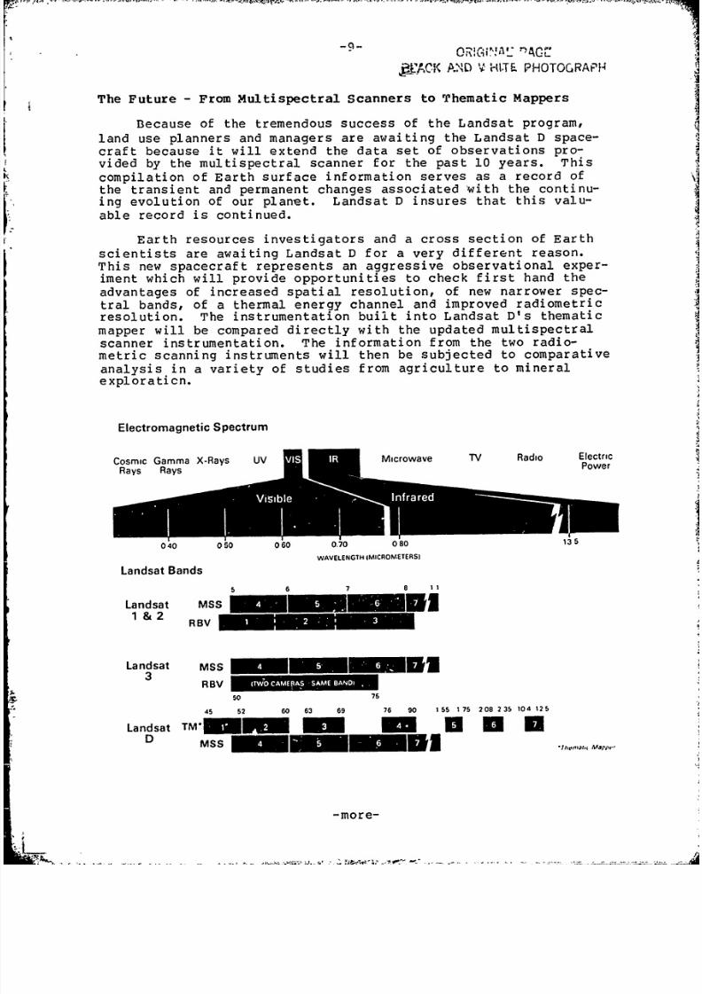
The Future - From Multispectral Scanners to Thematic Mappers
Because of the tremendous success of the Landsat program,
land use planners and managers are awaiting the Landsat D space-
craft because it will extend the data set of observations pro-
vided by the multispectral scanner for the past 10 years. Thiscompilation of Earth surface information serves as a record ofthe transient and permanent changes associated with the continu-ing evolution of our planet. Landsat D insures that this valu-
able record is continued.
Earth resources investigators and a cross section of Earth
scientists are awaiting Landsat D for a very different reason.
This new spacecraft represents an aggressive observational exper-
iment which will provide opportunities to check first hand the
advantages of increased spatial resolution, of new narrower spec-
tral bands, of a thermal energy channel and improved radiometricresolution. The instrumentation built into Landsat D's thematic
mapper will be compared directly with the updated multispectralscanner instrumentation. The information from the two radio-
metric scanning instruments will then be subjected to comparative
analysis in a variety of studies from agriculture to mineralexploration.
Electromagnetic Spectrum
Cosmic Gamma X-Rays UV Microwave TV Radio ElectricRays Rays -Power
0 0 0 0 0 60 0.70 0 80 5
WAVELENGTH IMICROMETERSI
Landsat Bands
5 6 7 8
Landsat MSS
1 &2 RB V
Landsat MSS - -
Rl3V 11111.
so 75
45 52 60 63 69 76 90 155 17 5 208 235 104 125
Landsat TM - - U a UD sMSS iiini5w m 7j,- Mamro
-more-

8/7/2019 Landsat D Press Kit
http://slidepdf.com/reader/full/landsat-d-press-kit 11/43
Applications of Spectral Bands
0.45- 0.52,JM
BATHYMETRY IN LESS TURBID WATERS; SOIL/VEGETATION DIFFERENCES; DECIDUOUS/CONIFEROUS
DIFFERENTATION; SOIL TYPE DISCRIMINATION
0.52 - 0.60,AM
- INDICATOR OF GROWTH RATE AND VEGETATION VIGOR BECAUSE OF SENSITIVITY TO GREEN
REFLECTANCE PEAK AT 0.55)JM, SEDIMENT CONCENTRATION ESTIMATION; BATHYMETRY IN
TURBID WATERS
0.63 - 0.69 JM
- CHLOROPHYLL ABSORPTION/SPECIES DIFFERENTATION; ONE OF BEST BANDS FOR CROP CLASSIFICATION,
VEGETATION COVER AND DENSITY; WITH THE 0.52 - 0.60 PM BAND IT CAN BE USED FOR FERRIC IRON
DETECTION; ICE AND SNOW MAPPING
0.76 - 0.90 PM
- WATER BODY DELINEATION; SENSITIVE TO BIOMASS AN D STRESS VARIATIONS
1.55- 1.75)JM
- VEGETATION MOISTURE CONDITIONS AN D STRESS; SNOW/CLOUD DIFFERENTATION; MA Y AID IN
DEFINING INTRUSIVE OF DIFFERENT IRON MINERAL CONTENT
2.08- 2.35 PM
- DISTINGUIFL HYDROTHERMALLY ALTERED ZONES FROM NON-ALTEREDZONES/MINERAL
EXPLORATION; SOIL TYPE DISCRIMINATION
10.4- 12.5 PM
* SURFACE TEMPERATURE MEASUREMENT; URBAN VERSUS NON-URBAN LAND USE SEPARATION; BURNED
AREAS FROM WATER BODIES
-more-

8/7/2019 Landsat D Press Kit
http://slidepdf.com/reader/full/landsat-d-press-kit 12/43
The Thematic Mapper's Spectral Resolution
The unique and powerful advantages of the thematic mapper
come in its multispectral observations. The experience gained in
multiple agency experiments such as LACIE and AgRISTARS has shownthat narrower spectral bands in the visible and near infrared
portions of the electromagnetic spectrum are needed. These exper-iments have also shown that new spectral bands in the middle (13 micron) and far (4 - 20 micron) infrared are needed to distin-guish between crops that appear very similar in multispectralscanner observations. Typically crops such as wheat and barley,or corn and soybeans can be confused when using multispectralscanner classification techniques.
The mineral and petroleum exploration scientists have also
wanted new and narrower spectral bands so better geological sur-veying and exploration procedures could be tested using the ad-
vantages of a high altitude observation platform in space.
The thematic mapper uses significantly narrower bands in the
green, red and near infrared compared to the multispectral scan-ner. These narrower bands allow the increased reflectance ofvegetation in the green (0.52 - 0.6 micron vs. 0.5 - 0.6 micron)and near infrared (0.76 - 0.9 micron vs. 0.7 - 1.1 micron) to bemeasured more precisely by the thematic mapper. In the case ofthe near infrared, the narrower spectral band reduces the chanceof obscuration of the land surface by water vapor in the atmos-phere. A narrower band in the red regio.n (0.63 - 0.69 micron vs.
0.6 - 0.7 micron) will allow differences in chlorophyll absorp-tion associated with various plants to be distinguished better.
With these improvements the thematic mapper offers distinctadvantages relative to the multispectral scanner for vegetationand land cover mapping.
-more-
- . d '. *

8/7/2019 Landsat D Press Kit
http://slidepdf.com/reader/full/landsat-d-press-kit 13/43
-12-
THEMATIC MAPPER (TM) MULTISPECTRAL SCANNER (t4SS)
RADIOMETRICRADIOMETRIC
SENSITIVITYSENSITIVITY
SPECTRAL BAND MICROMETERS (NEAP) MICROMETERS (NE AP )
1 0.45 - 0.52 0.8 0.5 - 0.6 .57
2 0.52 - 0.60 0.5 0.6 - 0.7 .5?
3 0.63 - 0.69 0.5 0.7 - 0.8 .65
4 0.76 - 0.90 0.5 0.8 - 1.1 .70
5 1.55 - 1.75 1.0
6 2.08 - 2.35 2.4
7 10.40 -12.50 0.5K (NEAT)
GROUND IFOV 30M (BANDS 1-6) 83M (BANDS 1-4)
120M (BAND 7)
DATA RATE 85 MB/S15 MB/S
QUANTIZATION LEVELS 25664
WEIGHT 246 KG58 KC
SIZE 1.1 x 0.7 x 2.OM 0.35 x 0.4 x 0.9!:
POWER 345 WATTS 81 WATTS
-more-

8/7/2019 Landsat D Press Kit
http://slidepdf.com/reader/full/landsat-d-press-kit 14/43
-13-
The major advantages of the thematic mapper for renewable
resources and land cover studies, however, come from the addition
of new spectral bands. A new band measuring reflected sunlight
in the blue - greer. (0.45 - 0.52 micron) portion of the spectrum
will allow further differences in chlorophyll absorption to be
differentiated.
Natural color images of the Earth's surface features will
now be possible for the first time on a Landsat. The multispec-
tral scanner only allowed false color images where grass and
vegetation often appeared red. The addition of the blue-green
band on the thematic mapper will also be useful in allowing
greater depths to be seen through relatively clear water. This
is useful for bathymetric measurements first developed with the
multispectral scanner. Coastal water bottom topography mapping,
reef mapping, uncharted island surveying and atoll surveying are
all possible new uses for the thematic mapper data.
The middleinfrared bands of the thematic mapper (1.55 -
1.75 microns and 2.08 - 2.35 microns) are new and are expected to
be particularly useful in vegetation mapping because of the sen-
sitivity of these bands to the amount of water actually present
in the plant leaves. Observations in these spectral bands should
allow plants to be identified and differentiated based on their
differences in leaf water content (succulency).
In addition to the plant identification characteristic,
these middle infrared bands will also be useful in helping to
assess plant health and condition based on its water content.
Because clouds often obscure snow covered fields, these
middle infrared bandswill also be useful in assisting in snow
cover mapping. In these spectral bands snow appears as very dark
while clouds remain quite bright. Multispectral scanner images
could not detect the difference between clouds and snow cover.
The multispectral qualities of the thematic mapper will
improve significantly the quality of geological maps produced
from Landsat D data. The new infrared bands will permit geo-
logists to spectrally differentiate a wider variety of rock and
soil types. Experimental studies conducted during the develop-
ment of the thematic mapper have shown that the two middle infra-
red bands will be most useful for detecting variations in the
type and abundance of clay minerals exposed at the Earth's sur-
face. Clay mineralscan be formed as the result of surface wea-
thering or they can be produced by subsurface hydrothermal alter-
ation. Hydrothermal alteration occurs when heated, mineral rich
groundwater circulates through existing rock. This process often
accompanies the emplacement of specific mineral deposits such as
copper, lead, zinc and uranium.
-more-

8/7/2019 Landsat D Press Kit
http://slidepdf.com/reader/full/landsat-d-press-kit 15/43
-14-
Thematic mapper data will also be able to distinguish hydro-
thermal clay minerals from other species in semi-arid regions and
can potentially contribute to base metal exploration in certain
geographies. This same clay mineral/clay delineation capability
may also be useful for soil type mapping.
The emitted thermal energy band (10.4 - 12.5 microns) mea-
sures surface temperature. This capability will allow another
fundamental dimension of multispectral data to be added to that
already present in thematic mapper bands measuring reflected
solar energy. By measuring the temperature of plants, the plant
condition or health can be identified. Differences in the heat
capacity characteristics of different plants will further improve
the identification of individual plant types.
This same principal will be used for identifying and mapping
surface composition for geologic studies. This band should allow
differences in heat capacity(thermal inertia) to be used for
mineral and petroleum exploration.
The real advantage of this new thermal energy band, however,
is not truly understood and will have to await the Landsat D
investigations.
Spatial Resolution
The thematic mapper will have a 30 by 30 m (98 by 98 ft.)
instantaneous-field-of-view as compared to an 82 by 82 m (269 by
269 ft.) field-of-view in the Landsat D multispectral scanner or
a 79 by 79 m (240 by 240 ft.) field-of-view for the Landsats 1,
2 and 3. The thematic mapper field-of-view coversan
areaone
seventh the area of the multispectral scanner and will allow much
smaller features on the surface to be identified and measured.
In the case of agricultural inventories the multispectral
scanner was only able to monitor relatively large fields -- (1.6
hectares (40 acres) -- such as those in the North American Great
Plains and the wheat producing regions of Northeastern Europe and
Northern Asia.
The thematic mapper can inventory much smaller fields 2 to
4 hectares (5 to 10 acres) such as those in the eastern and
southern United States and the small fields of China, India,
Europe and South America.
For land use mapping and planning the thematic mapper spa-
tial resolution should allow features which were blurred in mul-
tispectral scanner observations to be mapped much more easily and
accurately. Urban planners concerned with changing land use pat-
terns and hydrologists investigating storm water management
should be able to use thematic mapper data much more effectively
than multispectral scanner data.
-more-

8/7/2019 Landsat D Press Kit
http://slidepdf.com/reader/full/landsat-d-press-kit 16/43
-15-
The improved spatial resolution of the thematic mapper willlso benefit geologic mapping. The 30-m (98-ft.) pixel (picturelement, a single scan data point) of the thematic mapper willenable photointerpreters to detect smaller scale land forms andiver channels. It will also permit geologists to recognize moresolated occurrences of specific rock types.
Radiometric Resolution
In order to measure subtle differences in reflected oremitted energy with a radiometer like the multispectral scannernd thematic mapper, it is important to be able to quantify dif-ferences in the measured energy over the entire dynamic range ofhe sensing instrument and to perform the quantization in as manyiscrete levels as practical (within limits imposed by the elec-tronic noise generated by the system itself). The multispectralscanner measurements are broken into 64 levels. This levelofuantization has allowed differences of reflected energy on theorder of 1.5 percent to be measured. The thematic mapper and itsssociated electronics will permit each of the seven spectralbands to be quantized into 256 levels. The thematic mapper willbe able to detect differences in reflected light energy as smallas 0.5 percent. This represents a three-fold improvement whichs expected to translate into a 10 to 20 percent improvement inthe multispectral classification performance of the thematicmapper as compared to the multispectral scanner.
The Landsat D Image Data Quality Analysis Program
In order to assess the nearly two times improvement inspec-tral discrimination, the nearly three times improvement in spa-tial resolution and the three times improvement in energy sensi-ivity, the Landsat D program includes an investigation programestablished to assess the performance of all of the Landsat Dystems, but particularly the thematic mapper. The Landsat Dystems performance will be examined in light of the specifica-tions established for them by the scientific, engineering andresource management communities. The performance and usefulnessof the Landsat D multispectral scanner will be assessed.
The investigations program extends from 1982 through 1985and at present involves 25 different investigations proposed byniversity, private industry, government agencyand foreignscientists. Many of these investigations, including some fromrivate industry, will be conducted at no cost to NASA due to thegreat interest generated by the potential application of thethematic mapper.
-more-

8/7/2019 Landsat D Press Kit
http://slidepdf.com/reader/full/landsat-d-press-kit 17/43
-16-
DESCRIPTION OF OPERATIONAL SYSTEMNASA will launch Landsat D, check out the spacecraft sys-tems, establish the precise orbit and demonstrate the system tobe fully operational before transferring management to NOAA. Thethematic mapper will remain an experimental
development projectunder direct NASA (Goddard Space Flight Center) management. Pub-lic domain data from the mapper will be provided to NOAA fordistri buti on.
Under the single manager approach adopted by the federalgovernment, NOAA will be responsible for controlling the space-raft, scheduling the sensors, processing and distributing datafrom the multispectral scanner and reproducing and distributingpublic domain data from the thematic mapper.
The Landsat D program is keyed to user requirements andreliable data product delivery.
Information from Landsat is produced from the rnultispectralscanner both as computer compatible (on tape) and in the form ofmagery (photo product). Each Landsat scene covers an area of85 by 185 km (115 by 115 mi.).
The multispectral scanner is essentially the same as thoseused on previous Landsat spacecraft. It acquires data simul-taneously from four bands of the visible and near-infrared por-ions of the light spectrum. False color composite photos can beroduced by combining several bands of information through fil-ters onto color film.
The resulting pictures produce a greatdeal of useful datain color. Vegetation appears in various shades of red, dependingon species, stage of growth and health of the plants. Cities andhighways appear blue. Hater comes out in shades from whitethrough blue to black, depending on the depth, sediment load andther characteristics.
Data from the multispectral scanner will be received at theNOAA ground station facility developed by NASA, located atGoddard Space Flight Center, where it will be processed into aformat suitable for archiving. The data will then be transmittedvia communications satellite to the Department of Interior EROSData Center for further processing into computer compatible tapesr pictures.
To provide service to Landsat customers, NOAA has enteredinto an agreement with Interior to continue EROS Data CenterLandsat data activities under NOAA management. The NOAA Landsatactivity at the center will be the hub for customer services.
Information similar to that produced by the multispectralscanner but in much greater detail will be produced by thethematic mapper.
-more-

8/7/2019 Landsat D Press Kit
http://slidepdf.com/reader/full/landsat-d-press-kit 18/43
-17-
The thematic mapper covers the same areas as the multi-spectral scanner but with finer resolution using seven bands ofhe spectrum. Data from the thematic mapper will be processed byASA and-scenes placed in the public domain by forwarding to theROS Data Center for sale to the public.
PLANNING TO MEET USER NEEDS
In November 1979, NOAA was designated by the federal govern-ment to manage all operational civilian remote sensing activitiesrom space. NOAA was selected as the operating agency because ofts experience in managing and operating the National Environmen-ta l Satellite System, which has involved 24 environmental satel-ites since 1966.
A series of public meetings on Landsat, now in progress, isimed at bringing the public up to date on the planned Landsatinformation system. These meetings are a continuation of a Land-at exchange program begun in early 1980 by NOAA which seeks tobtain advice from the public about how best to structure themultispectral scanner basic data set.
Establishment of the Landsat information system began with aseries of five regional meetings in 1980 to request public assis-ance in its development. The meetings produced more than 700esponses from business firms, trade associations, educationalinstitutions, state and local government agencies and privatecitizens.
Policy issues raised at the meetings included the types ofnstruments to be carried aboard the spacecraft, their capabili-ties, how quickly and in what form the data should be made avail-ble and how charges would be assessed.
NASA and NOAA jointly sponsored a series of conferencesthroughout the country in early 1981 to help plan a distributionsystem responsive to user needs. NASA-sponsored conferences re -orted the results of state and local government uses of Landsatata for natural resource and environmental monitoring. NOAA-sponsored conferences, held after the ones by NASA, describedsome of the products and services possible.
In December 1981, NOAA announced a new service providingspecial acquisition of Landsat data not regularly scheduled forensing and new prices for Landsat products. This new Landsatservice was created to meet a longstanding demand from certainusers for collection and rapid distribution of multispectralscanner data for Earth locations not scheduled for routinecollection.
-more-

8/7/2019 Landsat D Press Kit
http://slidepdf.com/reader/full/landsat-d-press-kit 19/43
MISSION DESCRIPTION
Landsat D will be launched on a Delta 3920 vehicle into a
circular, near polar, Sun-synchronous orbit. The launch time is
selected to achieve a descending node equatorial crossing between
9:30 and 10:00 a.m. local time. The nominal orbital altitudewill
be 705 km (380 n. mi.) at a 98.2 degree inclination with a 16-day
repeat cycle and a period of 98.9 minutes.
The spacecraft is contained in the 2.2-m (86-in.) diameter
shroud envelope of the Delta at launch. The 1.8-m (6-ft.) relay
satellite tracking antenna is stowed in the forward shroud area
extending into the conical portion of the shroud. The rear of
the antenna assembly is preloaded to the antenna boom and forward
portion of the spacecraft structure to provide a rigid tie-down
during launch.
The solar array assembly is stowed for launch between the
upper spacecraft support structure and the Delta shroud. Thepanels are rigidly tied to the primary spacecraft structure at
four locations during launch.
Landsat D will be imaging the same 185-km (115-mi.) swath of
the Earth's surface every 16 days. During this 16 day cycle, t:1e
entire Earth, except for small areas around both poles, can be
imaged.
Image data will be transmitted in realtime at Ku band via
the Tracking and Data Relay Satellite once it is launched in
1983. Once the Landsat D begins using the TDRSS, communication
will be through the relay satellite ground station at White
Sands, N.M. Thematic mapper data will be recorded at the groundstation and then relayed to Goddard via communications satellite.
Multispectral scanner data can be either recorded at the White
Sands station and relayed to Goddard or relayed in real time to
Goddard for processing.
Until the TDRSS is operational, the downlink communications
mode for MSS data will be through the Landsat D direct access S
band link. The S band is also provided for compatibility with
existing Landsat 1, 2 and 3 ground stations in foreign countries.
Thematic mapper data can be transmitted directly to the ground at
X band before the TDRSS is operational. The X band can be used
instead of or in addition to the Ku band TDRSS communications
modes.
Spacecraft telemetry and command communications are through
the S band system, either directly through the TDRSS (when avail-
able) or through the existing ground spacecraft tracking and data
network (managed ',y oddard).
-more-

8/7/2019 Landsat D Press Kit
http://slidepdf.com/reader/full/landsat-d-press-kit 20/43
-19-
U.S.-required foreign multispectral scanner data will beacquired at four foreign receiving stations and sent to theUnited States. The four stations are in Sweden, Brazil, Japanand Australia. Data tapes acquired at those stations will beprocessed at Goddard after receipt.
Ephemeris data, required for spacecraft control and forground processing and image correction is computed by Goddard.Following the checkout of the system, ephemeris will be availablethrough the Landsat D directly, using the global positioningsystem receiver.
LAUNCH VEHICLE DESCRIPTION
The Landsat D spacecraft will be the first mission launchedby the new Delta 3920, which is a thrust-augmented NASA Delta3910 launch vehicle. This will be the 163rd flight for Delta.
Of the previous 162 flights, 149 have successfully placed theirsatellite payload in orbit.
DELTA 3920 VEHICLE COMPONENTrS
SPACECRAFT FAIRING -
- SPACECRAFT
ATTACH FITTING
FAIRING
(26 FT)
GZ.IDANCE SYSTEM (DIGS) - _
SUPPORT CONE L
SECOND STAGEMINI-SKIRT 0 (19.5 FT) INTERSTAGE
AEROJET-ITIP ENGINE A¢Eg
FUEL TANK
CENTER BODY
LO X TANK-
FIRST STAGE
AAA 9(73.6FT)
THRUST AUGMENTATION
THIOKOL CASTOR IV MOTORS
(9 LOCATIONS)
ENGINE COMPARTMENT
ROCKETDYNE H-1 ENGINE
-more-
. 4 ,-l. .- -. . - - -- - .--.--. .-A.. d- - - -

8/7/2019 Landsat D Press Kit
http://slidepdf.com/reader/full/landsat-d-press-kit 21/43
-20-
DELTA 3920 LAUNCH VEHICLE CHARACTERISTICS
STRAP-ON STAGE I STAGE II
Length 11.3m 21.3m 700.0cm
(37.0 ft) (70.0 ft) (276 in)
Diameter 101.6 cm 243.3 cm 175.3 cm
(40 in) (96 in) (69 in)
Engine Type Solid Liquid Liquid
Engine Manufacturer Thiokol Rocketdyne Aerojet
Designation TX-526 RS-27 ITIP
Number of Engines 9 1 (+2VE) 1
Specific Impulse Avg. 229.9 262.4 319
Thrust (per engine) (Avg.) 407,000 N 911,840 N 41,969 N(91,520 lb) (205,000 lb) (9,443 lb)
Burn Time 58.2 (sec) 228 (sec) 445 (sec max)
Propellant TP-H-8038 RP-I A-50
(LOX oxid.) (N204 oxid.)
Delta is managed for NASA's Office of Space Transportation
Operations by the Goddard Space Flight Center. Launch operationsmanagement is the responsibility of the Kennedy Space Center, Fla.
The Delta 3920 is 35.5 m (116 ft.) long, including thespacecraft shroud. Liftoff weight is 189,087 kg (415,990 lb.)
and liftoff thrust is 2,058,245 newtons (547,504 lb.) including
the startup thrust of six of the nine strap-on solid rocketmotors (the remaining three motors are ignited at liftoff plus 60
seconds).
The first stage booster will be an extended long-tank Thor
powered by the Rocketdyne RS-27 engine. This engine uses hydra-
zine (RP-1) fuel and liquid oxygen oxidizer. Pitch and yaw steer-
ing is provided by gimballing the main engine. Vernier enginesprovide roll control during powered flight and coast.
'Phe Delta 3920 incorporates a new second stage consisting oflarge diameter propellant tanks coupled with the new Aerojet
Liquid Rocket Company's AJ-10-118 improved transtage injectorprogram (IVIP) engine. This stage is powered by a liquid propel-
lant engine using N204 as oxidizer and Aerozene 50 as fuel.
Pitch and yaw steering during powered flight is provided by gim-balling the engine. Roll steering during powered flight and
coast is provided by a nitrogen gas thruster system.
-more-

8/7/2019 Landsat D Press Kit
http://slidepdf.com/reader/full/landsat-d-press-kit 22/43
-21- ORIGINAL 'XE iOF pOOR QUALITY
DELTA 3920 SECOND STAGE COMPARISONS
Delta Delta3910 3920
Key Comparisons-- 54.5 In 68.8 In
Weight (Lbs)
1863 - Dr y - 1.886 '10.072 - Total Propellants - 13.291
< t10,027 - Useable Propellants - 13.24411,979 - Flight - 15.224 ~
PerformanceA
301.3 - ISP (Sec) - 319.2I f '3.04 X 10⁶ - Impulse (Lb Sec) -4.2 X 10 6
| /s @| 9425- Thrust (Lbs) - 944346:1 - Expansion Ratio- 65:1234.9 Subsystems
TRW - Engine - AerojetTR-201 iSustes ITIP ~ 7
/ . No Basic Cag nSbytm
The guidance and control system of the Delta vehicle islocated on top of the second stage. The strap down Delta iner-tial guidance system (DIGS) provides the guidance and controlsignals for the total vehicle from liftoff through attitudeorientation. The system is composed of a digital computer pro-vided by Delco (General Motors Corp.) and either the inertial
measurement unit (IMU) provided by Hamilton Standard (UnitedTechnologies) or the Delta redundant inertial measurement system(DRIMS) developed by McDonnell Douglas Astronautics Co.
First and second stage telemetry systems are similar, bothcombining the use of pulse duration modulation and frequencymodulation. Critical vehicle functions are monitored duringascent.
At liftoff, six Castor IV solid rocket motors are ignited onthe launch pad and burn out at 57.8 seconds. At 60 seconds theremaining three solids are ignited and burn out at 118 seconds.The six ground-lift solid motors are jettisoned in groups of
three at 78 and 79 seconds with the final set jettisoned at 123.5seconds. Main engine cutoff (MECO) occurs at 226.6 seconds.First stage separation occurs at 234.6 seconds with the space-craft fairing jettisoned at 245 seconds.
At second stage cutoff (SECO) the vehicle is at an altitudeof 196 km (105 n.mi.) and on an orbital trajectory with an apogeeof approximately 716 km (387 n.mi.) and a perigee of 187 km (101n.mi.) At first apogee the second stage is restarted and burnsfor 15 seconds to circularize the orbit at 696 km (376 n. m.).
-more-

8/7/2019 Landsat D Press Kit
http://slidepdf.com/reader/full/landsat-d-press-kit 23/43
-22-
LANDSAT D FLIGHT SEQUENCE OF EVENTS
EVENT TIME (SEC)
LIFT-OFF 0.0
6 SOLID BURNOUT 57.8
3 SOLID IGNITION 60.0
SEPARATE 3 SOLIDS 78.0
SEPARATE 3 SOLIDS 79.0
3 SOLID BURNOUT 118.0
SEPARATE 3 SCTLIDS 123.5
MAIN ENGINE CUTOFF (MECO) 226.6
STAGE I-II SEPARATION 234.6
STAGE II IGNITION 239.6
JETTISON FAIRING 246.0
FIRST CUTOFF - STAGE II (SECO 1) 650.3
BEGIN MANEUVER TO COAST ATTITUDE 700.0
COMPLETE MANEUVER TO COAST ATTITUDE 955.0
RESTART STAGE II 2890.6
SECOND CUTOFF - STAGE II (SECO 2) 2905.2
BEGIN MANEUVER TO SPACECRAFT SEPARATION ATTITUDE 2940.0
COMPLETE MANEUVER TO SPACECRAFT SEPARATION ATTITUDE 3130.0
SPACECRAFT SEPARATION, ACTIVATE RETRO SYSTEM 3197.1
FIRST DESCENDING NODE (FOLLOWING INJECTION) 6578.9
-more-
.~, ,~1...---.. ---- 7-; a.- s. . >;. ~

8/7/2019 Landsat D Press Kit
http://slidepdf.com/reader/full/landsat-d-press-kit 24/43
-23-
H ZZH
E4 CNM (Z.
H 4 0i 1 -- Z r-I-4 r:U ,-4
LCOC2%DO
I E uDO E-
I u)
0
z0
E-1 DE-
U) -)
0 20
IZ ZN Cti
H 0>U
0>
U))
DE4\H I / U
\ X ° Zo
\i I D H: U)
\ < a HIl H
HE-E- ;I
-m re r- 'T c
0 /0
04 H
Zr0 H~0>
-more-

8/7/2019 Landsat D Press Kit
http://slidepdf.com/reader/full/landsat-d-press-kit 25/43
-24- ORiGINAL PXc-E ISOF POOR QUALITY
SPACECRAFT ACTIVATION
The Landsat D will be launched with one telemetry trans-mitter and one command receiver activated. The attitude controlystem will have the Earth sensors, Sun sensors, magnetometers,agnetictorquers, gyros and reaction wheels powered duringaunch.
One telemetry tape recorder will be recording and the on-oard telemetry processing computer will be activated. Separa-ion from the launch vehicle will occur during the first orbitver the Indian Ocean when in view of the Department of Defensendian Ocean tracking station, about 53 minutes after launch.
Separation will be followed by solar array deployment,approximately 13 minutes later. Earth pointing and solar arrayotation will be initiated during the first full orbit.
Orbit adjust maneuvers to position the spacecraft on itsominal ground track are planned to begin on day 6 and will re-uire about six days to complete.
The multispectral scanner will be activated on orbit 34 (day). Each band will be turned on separately. Bands 1 through 4f the thematic mapper will be sequentially activated on orbit 71day 6). Bands 5 through 7 will undergo an outgassing periodfter the orbit maneuvers are completed. A sequential activationf bands 5 through 7 will occur about day 36.
HIGH GAIN ANTENNA
GLOBAL POSITIONINGSYSTEM ANTENNA
\, - ANTENNA MAST
OMNI ANTENNA
ATTITUDE CONTROL \ WIDE BAND MODULEUBSYSTEM MODULE
), SUN SENSORS
< . S ~MULT I 1 5 PECT RA L
SCANNERPROPULSION--13N
-- SOLAR ARRAYODULEPANEL
POWER MODULE.THEMATIC MAPPER91IGNAL CONDITIONING AND
ICONTROL UNITS BAND ANTENNA
X BAND ANTENNA
-more-

8/7/2019 Landsat D Press Kit
http://slidepdf.com/reader/full/landsat-d-press-kit 26/43
-25-
ORIGINAL PAGE ISOF POOR QUALITY
DELTA LAUNCH CONFIGURATION
FF
ILI
SECTION B i - !
.. - t -- Z | SEPARAT ION PLANE
/ it!' A w st.. -. A
- -;- 619 PAYl-OAD .s.
alrACs FITTING /
FC, ON AA1--
-more-

8/7/2019 Landsat D Press Kit
http://slidepdf.com/reader/full/landsat-d-press-kit 27/43
-26-
ERLY CtBIT TIMEl
EVENT DAY (FRCM LAUNCH)(o=operational)
1 2 3 4 5 6 7 8 9 10 11 12 13 14
SOLAR AMAY DEPLOYMENT +
SOLAR ARAY YRTATION 0
A¶ITIUDE CONTROL ACTIVATICN + 0
STAR CATALOG LOAD + 0
E MERIS LOAD + o
SEN7SC PN1IVATION
S BAND MSS +/O
X BAND MSS +/0
X BAND 'TM (1-4) +/oX BAND IM/MSS +/0
X BAND 'TM (1-4)/MSS & S BAND MSS +/o
S, Ku BAND MSS & 85 mbps +/o
X, Ku BAND TM (1-4) & MSS +/o
S, X, Ku BAND TM & MSS +/O
S BAND MSS TO GDS 0
'TM (5-7) CJUGASSING +
¶I'M (5-7) 3OLDOMD -day 35
'IM 5-7) COOLDOWN ENDS -day 36
X BAND 'M (5-7) -day 36
GLOBAL POSITIONING SYSTEM
LANDSAT ALMW4NAC LOAD +
NDS ALMANAC LOAD +
NAVIGATE 1{DE +
HIGH GAIN XN'IV/BOCM
DEPLOYMENT +
INITIAL POSITICNDNG +
INITIAL PRE-TMRSS EXERCISE +
PROGRAM 'TRACK VALIDATICN +
CRBIT INJECTION ERRDR REMOVAL
CAL BURNS +
MAJCR BURN + +
TRIM (DRAG AKEUP) ++
-more-

8/7/2019 Landsat D Press Kit
http://slidepdf.com/reader/full/landsat-d-press-kit 28/43
-27-
SPACECRAFT DESCRIPTION
The main body of tne spacecraft consists of NASA's standardmultimission modular spacecraft (MMS) and the Landsat instrumentmodule (IM). The long dimension of the spacecraft body (rollxis) lies in the plane of the orbit. The yaw axis is orientedto the local vertical (parallel to the antenna mast). The pitchaxis is normal to the orbit plane and parallel to the axis ofotation of the solar array.
Principal spacecraft measurements follow:
Weight 1941 kg (4273 lb.)
Launch weight margin 127 kg (280 lb.)
Orientation control three axis momentum wheels
Power at mission start = 990 wattsat end of mission =814 watts
MULTIMISSIONMODULAR SPACECRAFT
SHUTTLE CRADLELOAD PIN 13)
TRANSIT;ON ADAPTER(INSTRUMENT MODULE
POWER INTERFACE)SYSTEM\Ad
SIGNAL CONDITIO1IH~ -ATITUDE CONTROLND CONTROL UNIT\ SYSTEM
MODULE SUPPOR
LN V UMBILICAL
CONNECTORCOHMUNICATION ANDDATA HANDLING SYSTEM
DELTA INTERFACE
PROPULSION MODULE
-more-

8/7/2019 Landsat D Press Kit
http://slidepdf.com/reader/full/landsat-d-press-kit 29/43
-28-
The principal instruments are the thematic mapper, locatedat the transition adapter between the instrument module and themultimission modular bus, and the multispectral scanner which islocated at the forward end of the instrument module. Eachinstrument uses an oscillating mirror to scan the Earth's surfacein the cross-track direction (perpendicular to the spacecraftground track). The motion of the
spacecraft along the groundtrack provides the along-track scan.
The thematic mapper uses a multistage passive radiatorcooler for temperature control of the thermal band detectors.The cooler is on the opposite side from the Sun.
The mast mount for the TDRSS communications assembly extendsabout 4 m (13 ftj above the spacecraft body to provide a clearfield-of-view to the relay satellite from horizon to horizon. AnL-band antenna mounted on this mast provides a link with theglobal positioning system satellites.
The solar array, with its single axis of rotation drivemechanism, moves at orbital track rate to follow the Sun. Itincoporates a fixed bend in the mount to orient the solarcollectors perpendicular to the Sun.
TDRS HIGH GAINANTENNA 'Ilk
TWO AXISGIMBAL
ANTENNA
JETTISON
MECHANISM UPPER AN D LOWER POWER HINGESSOLAR ARRAYDRIVE
SYNCHRONIZATION
* \ /CABLESINSTRUMENT '<1
MODULE /SPRING-LOADEDDEPLOYMENT
HINGES (6)SOLAR ARRAY
RETANYIOJETTISON/ \MECHANISM /\\
POWER HINGE .
SOLA ARRYiRETENT IONOLARARRAF TTI NGS

8/7/2019 Landsat D Press Kit
http://slidepdf.com/reader/full/landsat-d-press-kit 30/43
-29-
MNLTIMISSION MODULAR SPACECRAFT
T he multimission scanner bus provides four subsystems;power, attitude control, communications and data handling, andpropulsion. They are all mounted on a triangular structure. The
power, attitude control and comm/data subsystems are housed inidentical 1.2 by 1.2 by .3 m (48 by 48 by 12 in.) structures.The forward end of the structure provides the mating surface forthe mission-unique portion of the spacecraft and the aft endprovides the space and mounting for the propulsion module.
For Delta launches, the structure also provides the mechan-ical interface to the launch vehicle using an adapter mated tothe aft end of the spacecraft.
For retrieval in space, three trunions at the forward endmate to a support cradle which would be carried in the shuttlepayload bay.
Power Subsystem
The modular power subsystem receives electrical power fromthe solar array and conditions, regulates and controls this powerfor spacecraft use. During periods when the solar array isshadowed by the Earth, batteries supply spacecraft power. Thebatteries also supplement solar array power during periods ofpeak power demand.
Communications and Data Handling Subsystem
The comm/data subsystem provides telemetry data at two datarates, 8 kilobits/second during normal operations (with a 1 kbpsbackup capability for use during launch and in emergencies) and a32 kbps rate for onboard computer memory dumps to ground and pay-load correction data transmissions. Two standard tape recordersare included for recording and subsequent playback of telemetrydata.
Command is handled by a separate element of the subsystemand provides serial and pulse command capability. All communica-tions between Landsat D and the ground takes place through comm/data subsystem with the exception of the wideband sensor data.
The comm/data subsystem also contains an onboard computersystem with 64 kilobits of computer memory. The capability existsto reload onboard memory from the ground and to verify contentsof the memory from the ground. The computer is used for attitudecontrol, high gain antenna pointing/control, spacecraft/TDRSS/solar ephemeris computation, failure detection and correction anda variety of housekeeping telemetry functions.
-more-

8/7/2019 Landsat D Press Kit
http://slidepdf.com/reader/full/landsat-d-press-kit 31/43
-30-
OF POOR QuAlLtY]
Attitude Control Subsystem
This subsystem is a high precision, zero momentum system
with three-axis pointing accuracy to .01 degree with a drift rateof less than .000001 degree/second (10-6 degree/sec). The sub-system achieves this level of precision using an inertial refer-
ence unit with attitude updates from two star trackers.
A three-axis magnetometer and torquer magnets continuously
dump accumulated momentum from the momentum wheels. Backupmomentum dumping is available from the propulsion module.
Should the onboard system fail, a "safehold" mode is builtin to maintain the spacecraft in an Earth pointing position with-out the onboard computer. This system uses redundant Earth hori-
zon sensors as a two-axis (pitch/roll) reference system with agyrocompass for yaw reference.
Propulsion Module
This subsystem is mounted on the aft end of the spacecraft.It uses hydrazine fuel and includes both 11 newton (5 lb.) and0.5 N (0.2 lb.) thrusters. The large thrusters are used to makeorbit adjustments to maintain the 16 day repeat cycle. "'he largethrusters are also used for the orbit altitude changes needed forShuttle rendezvous (for retrieval). The small thrusters are usedfor initial stabilization and for backup momentum dumping.
TDRS ANTENNA
GPSANTENNA
INSTRUMENT MODULEPRIMARY STRUCTURE
ATTITUDE CONTROL MODULE OMNI ANTENNA SUN
MMS SENSORSSUPPORT
STRUCTURE L~OLAR% ARRAY
PANEL
/MULTISPECTRAL
- \ADAPTER SCANNER
PROPULSIONMODULE POWER COMMUNICATIONS
MODULE MODULE -WIDEBAND MODULE
THEMATIC MAPPER
-more-
- * - <- Fo <-e -r >fr i t -__ .

8/7/2019 Landsat D Press Kit
http://slidepdf.com/reader/full/landsat-d-press-kit 32/43
-31-
Global Positioning System
rThe global positioning system aboard the Landsat D space-
craft includes the L band antenna (mounted on the TDRSS antenna
mast), a preamplifier, oscillator and a receiver/processor
assembly. The system receives messages which are transmitted
continuously from the orbiting navigation satellites. It then
selects the optimum (based on signal strength, signal/noise
ratio) set of satellites from which to use data and calculates
a three dimensional position and spacecraft velocity for the
Landsat D.
The global positioning system is very similar to the tacti-
cal air navigation system now used by both military and civilian
aircraft. The GPS navsats are expected to be used eventually by
many of the same current users of TACAN.
In the early 1980s only six of the planned 18 navigation
satellites will be in orbit. Consequently there will be periods
ofan orbit when there are no navsats within view of the Landsat.
During these occulting periods the receiver/processor will esti-
mate position and velocity of the Landsat D using stored data
from the previous navsat communication.
Landsat D is the first NASA spacecraft to use the navsat
system. Consequently, an experimental period is planned for the
first several months of mission operations. During this period
ephemeris accuracies from the navsat system will be evaluated and
overall performance of the subsystem assessed.
Communications Links
LandsatD uses a wide variety of communications systems to
fulfill its mission. Narrowband (low bit rate S band) is used
for housekeeping telemetry, command and tracking. Wideband (high
bit rate Ku band) is used for Earth observation data communica-
tion for both the thematic mapper and the multispectral scanner.
Global positioning system communications is used for naviqation
and time computations.
Both S and Ku band communications are transmitted through
the high gain antenna to the relay satellite. S band data is
also transmitted through omnidirectional antennas for ground
spacecraft tracking and data network use (until the TDRSS is
launched this is the only path available for housekeeping/
command/control communication).
Existing foreign ground stations are equipped to receive 15
megabits/second multispectral scanner data through S band. How-
ever, the S band allocation on Landsat is inadequate to handle
the 84.9 mbps necessary for thematic mapper communication. To
service foreign ground stations, the Landsat D uses an X band
transmitter which can be received by upgraded ground stations.
-more-

8/7/2019 Landsat D Press Kit
http://slidepdf.com/reader/full/landsat-d-press-kit 33/43
-32-
Nideband Communications (Earth resources data)
The wideband communication subsystem enables the spacecraft
to transmit thematic mapper and multispectral scanner data to
both the relaysatellite and to ground stations. It urther
enables the spacecraft to acquire and track the relay satellite.
It cornsists of the radio frequency (RF) compartment, wide-
band module and gimbal drive assembly. The RF compartment is
integrally mounted on a 1.8 m (6 ft) Ku band high gain antenna.
The RF component contains the Ku band automatic tracking receiver
front end assembly and all components associated with the
transmitter.
The wideband module contains the mode selection and modula-
tion equipment used for both the Ku and X band links. It lso
contains the RF front end for the X banu equipment. The S band
transmittersare mounted in the instrument module above the wide-
band module. The S band antenna is mounted on the wideband
module next to the X band antenna.
All RF, dc power and signal lines interconnecting the RF
compartment and the wideband module are contained in a redundant
cable set. To prevent excessive attenuation within the coaxial
cables, the signals are sent at S band frequencies to the RF
compartment.
MULTISPECTRAL SCANNER
The multispectralscanner aboard Landsat D is very similar
to that flown on Landsat 1, 2 and 3. The optics and scan mecha-
nism have been modified to account for the lower altitude of the
Landsat D orbit.
The optics are a Ritchey-Cretien type focusing the scanned
Earth image on a set of detectors. The instrument includes four
spectral bands in the visible and near-infrared portions of the
spectrum. Bands 1 hrough 3 use photomultiplier tubes as detec-
tors. Band 4 uses silicon photo diodes. Each band has six de-
tectors for a total of 24 detectors in the multispectral scanner.
The multispectrz.l scanner scans cross track swaths of 185 km
(115 mi.) imaging sixscan lines across in each of the four spec-
tral bands simultaneously (for a 24 scan line total). The tele-
scope object plane is scanned by means of an oscillating flat
mirror located between the scene and the double-reflector optical
chain. The 14.9 degree cross track field of view is obtained as
the mirror oscillates.
The instantaneous field of view of each detector subtends an
Earth area square of 83 m (272 ft.) on a side from the nominal
orbital altitude. Field stops are formed for each line imaged
during a scan and foL each spectral band.
-more-

8/7/2019 Landsat D Press Kit
http://slidepdf.com/reader/full/landsat-d-press-kit 34/43
-33-
These stops are the square input end of an optical fiber.
Six of these fibers in each of the four bands are arranged in a 4by 6 matrix in the focused area of the telescope.
Light impinging on each glass fiber is conducted to an indi-
vidual detector through an optical filter, unique to the spectralband that detector is assigned to cover. An image of a line
across the swath is swept across each time the mirror scans,
causing a video signal to be produced at the multispectral
scanner electronics for each of the 24 channels. These signals
are then sampled, digitized and formatted into a serial data
stream by the multispectral scanner multiplexer. she signals in
bands 1 and 2 can be amplified by a factor of three (upon com-
mand) to increase response to low level scene radiance.
The along track scan is produced by the orbital motion of
the spacecraft itself. The nominal velocity causes an along
track motion of the subsatellite point on Earth of 6.82 km/sec
(4.23 m./sec - 15,228 mph)(not counting orbital perturbation andEarth rotation effects). By oscillating the mirror at a rate of13.62 Hz the subsatellite point will have moved 496 m (1,627 ft)
along the track during the 73.42 millisec active scan and retrace
cycle.
-more-

8/7/2019 Landsat D Press Kit
http://slidepdf.com/reader/full/landsat-d-press-kit 35/43
-34-
ORIGITOLpAGE IS
OF pOOR QUALI-lY
IZZSf
aa
Oftt
(I)0
°,1>10
00
Ba aNllotI$4 - --.
Cj C
0 -)
04
-more-

8/7/2019 Landsat D Press Kit
http://slidepdf.com/reader/full/landsat-d-press-kit 36/43
-35-
THEMATIC MAPPER
The thematic mapper is a seven band multispectral high reso-lution scanner. The instrument consists of a scanning mechanism,primary imaging optics, spectral band discrimination optics, de-
tectors, radiative cooler, inflight calibration device and oper-ating/processing electronics.
It will collect, filter and detect radiation from Earth in aswath 185 km (115 mi.) wide. The variation in radiant flux passingthrough the field stop onto the detectors creates an electricaloutput which represents the radiant history of that scan line.
The thematic mapper quantizes and multiplexes signals fromall of its detectors into a serial data stream for transmission.
Radiant energy (visible and thermal infrared) enters theinstrument through the Sun-shaded aperture. Scanning of the
field is accomplished by the scan mirror in the cross trackdirection and by the motion of the spacecraft in the along trackdirection.
The scan mirror is a 0.4 by 0.53 m (16 by 21 in.) ellipsewhich presents an equal area at all scan angles. The scan mirrormoves the view of the telescope back and forth across the ground
track.
The ground track is divided into 16 raster (scan) lines asit is scanned. There are 16 detectors for each of six bands andfour detectors for the seventh band. The band 7 detectors are
four times the area of the bands 1 through 6 detectors.
A scan line corrector preceding the detectors compensatesfor the southerly drift of the detector swath due to spacecraftorbital motion. Because of this the scan lines are straight and
perpendicular to the ground track.
Both directions of the scanning mirror are used for a high
scan efficiency. The corrector jumps ahead during the scanmirror turnaround so that the next set of scan lines is contig-uous with the previous set.
Because of this correction, the seven sets of detectors
representing the seven bands are effectively scanned across thesame fixed Earth point, although at a different time. Because ofthis, time correction is important also. The mirror is controlledand damped to move linearly and repeatably in order to providegeometrically accurate data.
The detector package for the visible and near infrared bands
(1,2,3 and 4) consists of four linear arrays of 16 silicon photodiode detectors, each located at the uncooled telescope focal
plane. The optics are of a Ritchey-Cretien telescope design.
-more-

8/7/2019 Landsat D Press Kit
http://slidepdf.com/reader/full/landsat-d-press-kit 37/43
-36- ORIGINAL PAGE ISOF POOR QUALITY
The mid-infrared bands (5 and 7) consist of 16 indium-antimonide photo diodes each. The far (thermal) infrared band(6) consists of four mercury-cadmium-telluride detectors. Thesensors for bands 5, 6 and 7 are located at the cooled telescopefocal plane. Detector signals are amplified, filtered
and routedto the thematic mapper multiplexer which digitizes the informa-tion, adds synchronization signals, timecode information, mirrorposition information and telemetry and forwards to the widebandcommunications subsystem.
ELECTRONICSMODULE THERMAL LOUVERS
POWER SUPPLYSECONDARY MIRRORI\ -ULTIPLEXEA
SCAN MIRROR -ASSEMBLY
A E L - XPRIME FOCAL PLANE
COOLED FOCAL PLANE
-- RADIATIVE COOLER
- D PRIMARY MIRROR INHWR ASSEMBLY
THEMATIC MAPPER
-more-

8/7/2019 Landsat D Press Kit
http://slidepdf.com/reader/full/landsat-d-press-kit 38/43
-37-
ORZGINsA pAGE' 'S
OF pOOR QUAkLTY
'9C C Y
~'
LW 4
- a\\
LLfJ
CL .
o~~~~~r CI°mg 4
H 3 >t r "-X 0 06,,,
= e' .' 4'-
II.N
isuu.....
-more-em ,,matr. r,

8/7/2019 Landsat D Press Kit
http://slidepdf.com/reader/full/landsat-d-press-kit 39/43
-38-
LANDSAT D GROUND PROCESSING SYSTEM
The Landsat D ground system consists of a series of separate
component systems and is located at the Goddard Space Flight
Center:
Control and simulation facility
This facility schedules spacecraft operations and communica-
tions network support, generates and transmits commands, acquires
and processes spacecraft telemetry, monitors and evaluates space-
craft performance and includes a full spacecraft simulator for
use in training and for failure analysis.
Multispectral scanner mission management facility
This facility is the central production control area for
all ground operations associated with the multispectral scanner.
Functions include processing requests for image products fromusers, maintaining a central data base of user requests, image
data acquisitions and products generated, scheduling the image
correction and product generation processes, controlling the
shipment of products, controlling inventory and management
reports.
Multispectral scanner image processing system
This facility processes correction data used in the image
generation process, generates image products on high density
digital tape, computer compatible tape and film. It also calcu-
lates the radiometric corrections necessary and computes the geo-
metric corrections and adds these to the archive tapes.
Thematic mapper mission management facility
This is the central production area for all ground thematic
mapper operations. Functions are similar to those of the multi-
spectral scanner management facility.
Thematic mapper image processing system
The functions of this facility are similar to those of the
multispectral scanner image processing system but require much
faster computer equipment and more complex computer software due
in part to the higher data rates associated with the thematicmapper (84.6 mbps for the thematic mapper versus 15 mbps for the
multispectral scanner). This facility is not expected to be on-
line until mid 1983.
-more-

8/7/2019 Landsat D Press Kit
http://slidepdf.com/reader/full/landsat-d-press-kit 40/43
-39-
Data receive, record and transmit system
This facility acquires and records the high bit rate digital
data received from the relay satellite or GSTDN ground stations.It also creates directories identifying the content of the datareceived and includes equipment for transmitting received, pro-cessed, data to the EROS Data Center.
Transportable ground station
This facility is an X band and S band receiving station atGoddard Space Flight Center. It receives the high bit rate digi-tal data and thematic mapper and multispectral scanner instrumentdata directly from the Landsat D spacecraft. It forwards re-ceived data to the data receive, record and transmit system andis the primary thematic mapper receiving station until the relaysatellite becomes operational in 1983. Following TDRSS opera-tions, the transportable ground station will be used for engi-neering evaluations.
Landsat assessment system
This facility is not part of the online Landsat D processingsystem. It is used for research and development work associatedwith the thematic mapper evaluation. It will bc used for develop-ing thematic mapper analysis techniques in selected Earth re-sources disciplines. During the first year of thematic mapperoperations, this facility will also be used to process thematicmapper images up to one scene per day.
-more-

8/7/2019 Landsat D Press Kit
http://slidepdf.com/reader/full/landsat-d-press-kit 41/43
-40-
NASA LANDSAT D PROGRAM MANAGEMENT
NASA Headquarters
Dr. Burton I. Edelson Associate Administrator for Space
Science and Applications
Dr. Stanley I. Weiss Associate Administrator for Space
Transportation Operations
Robert E. smylie Associate Administrator for Space
Tracking and Data Systems
Jesse W. Moore Director, Earth and Planetary
Exploration Division
Dr. Geoffrey Briggs Deputy Director, Science, Earth and
Planetary Exploration Division
James C. Welch Deputy Director, Technical, Earth
and Planetary Exploration Division
Harry Mannheimer Program Manager, Landsat D
Joseph B. Mahon Director, Expendable Launch
Vehicles Division
Peter Eaton Program Manager, Delta
Goddard Space Flight Center
Dr. Noel W. Hinners Director
William C. Keathly Director, Project Management
Jon R. Busse Project Manager, Landsat D
Luis Gonzales Deputy Project Manager, Landsat D
Frank L. Heddinger Deputy Project Manager (Resources),
Landsat D
Dr.Vincent Salomonson Project Scientist, Landsat D
Albert Lunchick Flight Assurance Manager, Landsat D
Joseph R. Schulman Systems Manager, Landsat D
Joseph Arlauskas Systems Manager, Instruments,
Landsat D
Lottie E. Brown Software Manager, Landsat D
-more-

8/7/2019 Landsat D Press Kit
http://slidepdf.com/reader/full/landsat-d-press-kit 42/43
-41-
Goddard Center (cont'd.)
Jerold Hahn Ground Data Processing Systems
Manager, Landsat D
William C. Webb Mission Operations Manger, Landsat D
Richard A. Devlin Spacecraft Manager, Landsat D
Oscar Weinstein Instrument Systems Manager, Landsat D
David W. Grimes Delta Project Manager
William R. Russell Deputy Delta Project Manager,
Technical
J. Donald Kraft Manager, Delta Mission Analysis
and Integration
Warner H. Hord Jr. Landsat Mission Integration Manager
Robert I. Seiders Mission Operations and NetworkSupport Manager
Ray Mazur Mission Support
Kennedy Space Center
Richard G. Smith Director
Thomas S. Walton Director, Cargo Operations
Charles D. Gay Director, Expendable Vehicles
Operations Directorate
Wayne L. McCall Chief, Delta Operations Division
Ray Kimlinger Chief, Delta Western OperationBranch
Pat Murphy Manager, SS Resident Office (VAFB)
C. R. Fuentes Spacecraft Coordinator
National Oceanic and Atmospheric Administration (NOAA)
Dr. John V. Byrne Administrator
Dr. Anythony J. Calio Deputy Administrator
James W. Winchester Associate Administrator
-more-

8/7/2019 Landsat D Press Kit
http://slidepdf.com/reader/full/landsat-d-press-kit 43/43
-42-
NOAA National Earth Satellite Service
Dr. John H. McElroy Assistant Administrator for
Harold Yates Acting Deputy AssistantAdministrator for Satellites
E. Larry Heacock Director, Office of Systems
Development
Russell Koffler Director, Office of Data Services
Edward F. Conlan Chief, Landsat Operations Division,
Office of Data Service
CONTRACTORS
General Electric Co. Landsat D spacecraft
Space Systems Division Landsat D ground system
Valley Forge, Pa.
Hughes Aircraft Co. Thematic Mapper
Los Angeles, Calif. Multispectral Scanner
Fairchild IndustriesMultimission Modular
Fairchild Space & Electronics Spacecraft
Germantown, Md.
McDonnell Douglas Corp. Delta 3920 launch vehicle
McDonnell Douglas Astronautics Co. Payload Assist Module(PAM)
Huntington Beach, Calif. Payload Stage
Rockwell InternationalDelta first stage engine
Rocketdyne Div. (RS-27)
Canoga Park, Calif.
Thiokol Corp.Castor IV strap-on engines
Huntsville, Ala.
Aerojet Liquid Rocket AJ10-118K (ITIP) second
Sacramento, Calif.stage engine
General Motors Corp. Guidance computerDelco Div.
Santa Barbara, Calif.
-end-