land-based facilities and in-situ testing sites for ocean engineering
TRANSCRIPT

Marine Research Infrastructures updated overview,
European integration and vision of the future Land-based facilities and in-situ testing sites for ocean engineering
WP 6 - Task 6. 4
D 6.4.1 _5
October 2012
Author: IFREMER (France)

2
Grant Agreement n° 249552
Acronym: SEAS-ERA
Title: Marine Research Infrastructures updated overview, European integration
and vision of the future – Annex 1 Atlantic region : D 6.4_5 Land-based facilities and
in-situ testing sites for ocean engineering
PROPRIETARY RIGHTS STATEMENT
THIS DOCUMENT CONTAINS INFORMATION, WHICH IS PROPRIETARY OF THE SEAS-ERA CONSORTIUM. NEITHER THIS DOCUMENT
NOR THE INFORMATION CONTAINED HEREIN SHALL BE USED, DUPLICATED OR COMMUNICATED BY ANY MEANS TO ANY THIRD
PARTY, IN WHOLE OR IN PARTS, EXCEPT WITH THE PRIOR WRITTEN CONSENT OF THE SEAS-ERA COORDINATOR. THIS RESTRICTION
LEGEND SHALL NOT BE ALTERED OR OBLITERATED ON OR FROM THIS DOCUMENT.
WP 6: Atlantic region
Task 6.4: Infrastructures in the Atlantic region
Task Leader/Author: J-F Masset, IFREMER
Milestone N°: 6.4.1

3
Table of content
1. Introduction
2. Land-based facilities and in-situ testing sites for ocean engineering and ocean observation
support
2.1 Landscape in Atlantic region, at a glance
2.2 Wave basins, per country
2.3 Water circulation flumes, per country
2.4 Other land-based testing facilities, per country
2.5 In-situ test sites, per country
3. European integration and vision of the future
3.1 Major European projects
3.2 Vision of the future

4
1. Introduction
A great variety of land-based facilities is necessary for ocean engineering purpose as for ocean observation
support : they are the essential testing facilities for design, preparation and qualification of the sea/sub-
sea sensors, instrumentation systems, mobile platforms and underwater vehicles before their operational
deployment at sea. This includes :
o Deep wave basins, wave flumes
o Water circulation canal,
o Marine instrumentation testing facilities,
o Material behaviour in sea water testing laboratories,
o Marine sensors calibration laboratories
o In-situ testing sites
A major role in the quality assurance process, for qualification of all the equipment before at sea
deployment.
A major role to test at small scale new concepts of offshore platforms and of marine renewable energies
devices.
Facilities listed include :
2D /3D wave basins, 2D wave flumes
Water circulation flumes
Various testing facilities for ocean and coastal engineering, for ocean/atmosphere interface studies
In-situ test sites for marine renewable energy system.
Not included :
Towing tanks for ship models, without wave generation
Cavitation tunnels for ship propeller
Hydraulic testing facilities not linked with coastal engineering
Information sources :
FP7 MARINET web site
FP7 HYDRALAB IV web site
Other hydrodynamic and ocean engineering facilities web sites

5
2. Land-based facilities and in-situ testing sites for ocean engineering
and ocean observation support
2.1 Landscape in Atlantic region, at a glance :
Country Wave basins or
flumes
Water circulation
flumes
Other land-based
facilities
In-situ test sites
Norway 1 1 2
Denmark 3 1 1
Germany 1 1 2 1
Netherlands 4 3 1
UK 4 2 3
Ireland 1 2
France 23 3 6
Spain 17 2 1
Portugal 1
2.2 Wave basins, per country
Norway :
MARINTEK, Norwegian Marine Technology Research Institute, Trondheim :
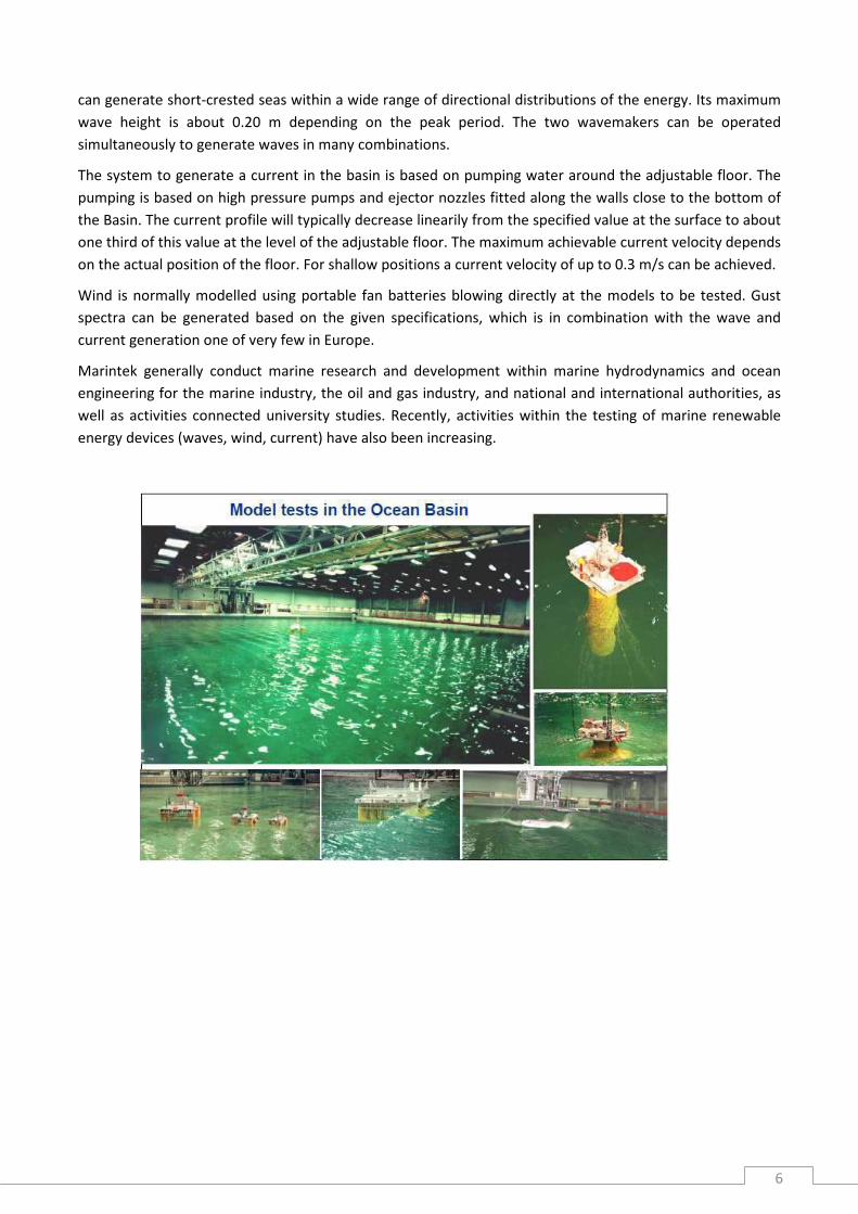
The Ocean Basin at MARINTEK is one of the largest wave basins in the world. The Basin is 50 m wide and 80
m long. It is equipped with two wavemakers that can generate wave conditions from two directions normal
to each other or in combined angles. The wave systems are documented to reproduce the full scale wave
conditions in an excellent manner. The wide extension of the Basin makes it suitable to test most kinds of
actual marine systems in large scale ratios which secures the correctness of the measurements and reduces
scale effects to a minimum. The depth of the Basin is 10 m, which places the Basin among the deepest in the
world. The large depth allows for large model scale ratio testing of most kinds of deep water applications.
The basin floor is movable and can be positioned at the desired depth for the testing, thus both deep and
shallow water tests can be offered. At zero depth the floor facilitates easy and efficient access for test set-up
and rigging. Its total capabilities makes it unique for offering large scale facility testing opportunities for
users with interests in hydrodynamic aspects.
The wavemaker along the 50 m side is a dual flap, hydraulically operated unit for generating of longcrested
regular and irregular waves. Maximum wave heights are nearly 0.9 m referring to regular waves. Irregular
waves can have up to 0.5 m significant wave height depending on the peak period. The other wavemaker,
fitted along the 80 m side of the Basin, consists of altogether 144 individually controlled wave flaps. This unit
6
can generate short-crested seas within a wide range of directional distributions of the energy. Its maximum
wave height is about 0.20 m depending on the peak period. The two wavemakers can be operated
simultaneously to generate waves in many combinations.
The system to generate a current in the basin is based on pumping water around the adjustable floor. The
pumping is based on high pressure pumps and ejector nozzles fitted along the walls close to the bottom of
the Basin. The current profile will typically decrease linearily from the specified value at the surface to about
one third of this value at the level of the adjustable floor. The maximum achievable current velocity depends
on the actual position of the floor. For shallow positions a current velocity of up to 0.3 m/s can be achieved.
Wind is normally modelled using portable fan batteries blowing directly at the models to be tested. Gust
spectra can be generated based on the given specifications, which is in combination with the wave and
current generation one of very few in Europe.
Marintek generally conduct marine research and development within marine hydrodynamics and ocean
engineering for the marine industry, the oil and gas industry, and national and international authorities, as
well as activities connected university studies. Recently, activities within the testing of marine renewable
energy devices (waves, wind, current) have also been increasing.

7
Denmark :
DHI, Hørsholm
The offshore wave basin at DHI is a large test facility
where realistic sea waves can be generated. The
facility is 30 m wide, 20 m long, and has an overall
water depth of 3 m with a deep central pit with 12m
depth. Realistic multi-directional (3D) waves can be
generated using the 60-flap wave maker, which also
can generate regular and irregular long-crested
waves. For irregular waves, stochastic as well as
deterministic, reproduction is possible. In addition to
the wave generation capabilities, steady current and
wind loading is available in the installation. The
facility is primarily used for experiments of water and
structure interaction with focus on moored floating
structures and deep water fixed structures.
The shallow water multi-directional wave basin is
equipped with a 3D wave maker with unique wave
generating and wave absorbing characteristics,
allowing e.g. for sophisticated modeling of coastal
engineering problems. Conventional type 2D wave
makers and, steady current and wind loading is
available in this installation. All necessary basic
peripherals such as instruments, amplifiers, and
computers for wave maker control and data logging
are available at both installations. The shallow water
basin is designed for flexible use to support research
on water and structure interaction (e.g. breakwaters
and dikes), water and environment (e.g. dispersion
processes) and water and sediment (scour processes
around coastal structures).
The experimental installations of DHI are today part of a large technological infrastructure which has been
actively engaged in developing hydrodynamic modelling tools for planning and design of coastal, offshore
and river structures and assessment of their impact on the marine environment.
8
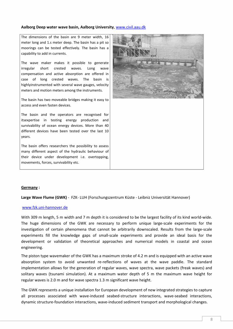
Aalborg Deep water wave basin, Aalborg University, www.civil.aau.dk
The dimensions of the basin are 9 meter width, 16
meter long and 1.s meter deep. The basin has a pit so
moorings can be tested effectively. The basin has a
capability to add in currents.
The wave maker makes it possible to generate
irregular short crested waves. Long wave
compensation and active absorption are offered in
case of long crested waves. The basin is
highlyinstrumented with several wave gauges, velocity
meters and motion meters among the instruments.
The basin has two moveable bridges making it easy to
access and even fasten devices.
The basin and the operators are recognised for
itsexpertise in testing energy production and
survivability of ocean energy devices. More than 40
different devices have been tested over the last 10
years.
The basin offers researchers the possibility to assess
many different aspect of the hydraulic behaviour of
their device under development i.e. overtopping,
movements, forces, survivability etc.
Germany :
Large Wave Flume (GWK) - FZK- LUH (Forschungszentrum Küste - Leibniz Universität Hannover)
www.fzk.uni-hannover.de
With 309 m length, 5 m width and 7 m depth it is considered to be the largest facility of its kind world-wide.
The huge dimensions of the GWK are necessary to perform unique large-scale experiments for the
investigation of certain phenomena that cannot be arbitrarily downscaled. Results from the large-scale
experiments fill the knowledge gaps of small-scale experiments and provide an ideal basis for the
development or validation of theoretical approaches and numerical models in coastal and ocean
engineering.
The piston type wavemaker of the GWK has a maximum stroke of 4.2 m and is equipped with an active wave
absorption system to avoid unwanted re-reflections of waves at the wave paddle. The standard
implementation allows for the generation of regular waves, wave spectra, wave packets (freak waves) and
solitary waves (tsunami simulation). At a maximum water depth of 5 m the maximum wave height for
regular waves is 2.0 m and for wave spectra 1.3 m significant wave height.
The GWK represents a unique installation for European development of new integrated strategies to capture
all processes associated with wave-induced seabed-structure interactions, wave-seabed interactions,
dynamic structure-foundation interactions, wave-induced sediment transport and morphological changes.

9
The following list should give a small impression on the most interesting scientific highlights recently
obtained by researchers using the FZK research infrastructure: Sea dykes, Grass dykes, Sea walls,
Breakwaters, Sediment transport, Scourat cylinders
Wave maker Revetment Cylindrical structure Sea wall
Netherlands :
MARIN Offshore basin
Dimensions : 45 m 36 m 10.2 m. A pit with an extra depth of 20 m
and a diameter of 5 m gives the opportunity to install systems up to 3000
m depth (prototype). The basin is mainly designed for testing models of
offshore structures which are fixed, moored or controlled by dynamic
positioning, in waves, wind and current.
Carriage speed up to 3.2 m/s
Wave generators
Wind generation, a free moving and positionable platform of 24 m
width, equipped with electrical fans is available.
Current : can be simulated with all kinds of profiles (hurricane, deep
water current etc). Divided over the water depth of 10.2 m, six layers of
culverts, each equipped with a pump, are installed.
Movable floor : The concrete movable floor has dimensions of 45 36 m
and a height of 1.75 m.
Stichting Deltares (locations : Delft, Marknesse) :
Deltares (merged from Delft Hydraulics and GeoDelft) offers an infrastructure of 6 unique experimental
installations in the field of environmental, hydraulic, geotechnical and morphological research. This meets
the increasing demand from researchers that need different installations for their research to achieve
scientific progress in the most complex areas of hydraulic research. The experimental installations offered by

10
Deltares are rare and costly, and some are even unique in that they do not exist elsewhere in Europe (or
even in the world). They offer the possibility of hydraulic research at a particularly large scale, high accuracy
and with special features.
The installations are:
Delta Flume. The Flume is 240 m long, 5 m wide and 7 m
deep and can generate regular or irregular waves up to a
height of 2.5 m. The flume can be used for large scale
experiments, to minimize scale effects. This installation is
unique because of its size in combination with a second-
order wave steering system and active re-reflection
compensation for short waves and long waves.
Vinjé Basin. The 50 m wide and 50 m long Vinjé Basin is a
unique installation for its capability of generating both
regular (periodic) and irregular (random) swell or short-
crested waves propagating at any direction within -50o to
+50o and reproducing directional spreading at the same
time. The directional wave absorbing characteristics of the
wave boards on 2 sides of the basin perpendicular to each
other enables an optimum control of the wave conditions
in the basin.
Schelde Flume. The 110 m long and 1.2 m deep flume is
equipped with a wave board capable of generating
second-order waves and it has a unique software-
controlled wave damping system. The flume is also
equipped to study wave-current interaction and has active
wave adsorption at the flume end. Its wave board steering
system is unique in Europe for its accuracy and versatility.

11
UK :
Narec Marine Test Site / Large Scale Wave Flume, New and Renewable Energy Centre Ltd, Blyth,
http://narec.co.uk
The Marine Test Site consists of 3 dry docks, the largest of
which is 125m long, 25m wide and 8m deep. The facility
contains a wave flume has the following characteristics;
· 60m long, 5m wide 7m deep
· Edinburgh designs multi paddle wave maker
· Peak period of 3.25s and Hmax of 1.0m
· Monochromatic, and spectral waves
· NI Labview Data Acquisition System
· Client office space
· Sea water
· Sited within a converted dry dock
Typical Testing Activities :
· Wave Energy Extraction Prototype testing (Power Take
Off systems, Hydrodynamic performance, extreme seas
survivability, etc)
· Subsea foundation performance testing (piling techniques
and stability, anchoring, etc)
· Cable and pipeline laying equipment trials and Trenching
· Prototype scale subsea deployment and assembly trails
12
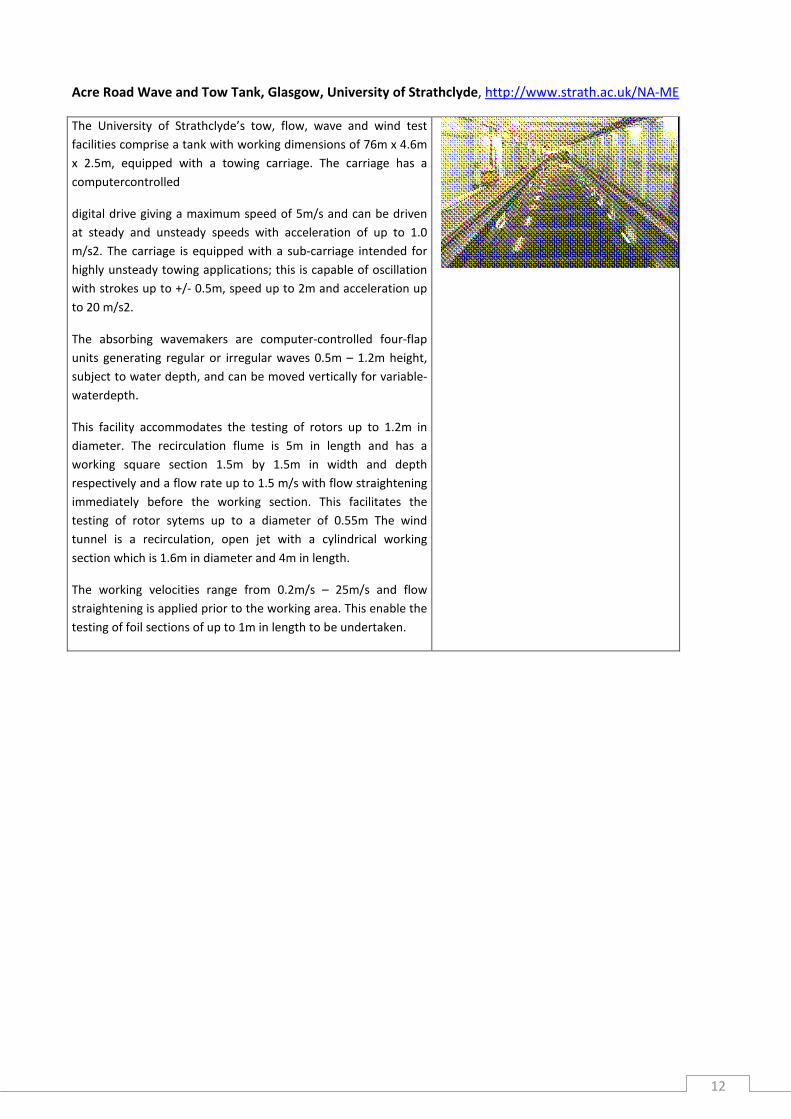
Acre Road Wave and Tow Tank, Glasgow, University of Strathclyde, http://www.strath.ac.uk/NA-ME
The University of Strathclyde’s tow, flow, wave and wind test
facilities comprise a tank with working dimensions of 76m x 4.6m
x 2.5m, equipped with a towing carriage. The carriage has a
computercontrolled
digital drive giving a maximum speed of 5m/s and can be driven
at steady and unsteady speeds with acceleration of up to 1.0
m/s2. The carriage is equipped with a sub-carriage intended for
highly unsteady towing applications; this is capable of oscillation
with strokes up to +/- 0.5m, speed up to 2m and acceleration up
to 20 m/s2.
The absorbing wavemakers are computer-controlled four-flap
units generating regular or irregular waves 0.5m – 1.2m height,
subject to water depth, and can be moved vertically for variable-
waterdepth.
This facility accommodates the testing of rotors up to 1.2m in
diameter. The recirculation flume is 5m in length and has a
working square section 1.5m by 1.5m in width and depth
respectively and a flow rate up to 1.5 m/s with flow straightening
immediately before the working section. This facilitates the
testing of rotor sytems up to a diameter of 0.55m The wind
tunnel is a recirculation, open jet with a cylindrical working
section which is 1.6m in diameter and 4m in length.
The working velocities range from 0.2m/s – 25m/s and flow
straightening is applied prior to the working area. This enable the
testing of foil sections of up to 1m in length to be undertaken.

13
The Edinburgh Curved Wave Tank, The University of Edinburgh, www.ed.ac.uk
The forty-eight paddle ‘curved’ tank was built in 2002 as a replacement
for the original eighty-nine paddle multi-directional ‘wide’ tank of 1977.
It was designed for model tests at around onehundredth scale. In plan,
the tank is built in the shape of a six-metre by twelve-metre right-
angled
triangle with the hypotenuse side replaced by a ninety-degree arc of a
circle made up of forty-eight wave flaps. The water depth is 1.2 metres,
which allows staff to work in waders. By avoiding parallel walls, the
unusual plan-form of the tank reduces the possibility of long-period
hard-to-kill seiche waves. The tank is capable of generating a wide
range of regular and pseudo random waves using recently redeveloped
control software.
The tank can be equipped, if required, with a portable array of nozzles
which allows inclusion of limited current capabilities
Edinburgh staff experience in multidirectional wave modelling extends
back to the 1970s, ranging from wave system model testing to
fundamental stochastic and non linear analysis. Recently novel
calibration dynamic calibration techniques have been added to the
capabilities, as have optical measuring techniques which are not subject
to the limitations of traditional immersion gauges when measuring non
linear waves. Similarly, recent work has greatly enhanced the capability
of the support team to robustly measure directional wave spectra.
Services currently offered by the infrastructure:
The size of the facility is such that it allows rapid use for small scale
experiments in a highly controllable, multidirectional wave
environment.
Shallow Water Wave Tank, Portaferry, Queen’s University Belfast, www.qub.ac.uk/research-
centres/eerc/ResearchThemes/CoastalandHydraulicEngineeringMRE/
The Hydraulic and Coastal Engineering group is part of the School
of Planning Architecture and Civil Engineering at Queen’s
University Belfast. The research group is internationally renowned
for research in wave power, fast ship wash, saline intrusion,
coastal modelling and wave impacts.
Current research is focussed on development of wave and tidal
energy devices through numerical and physical modelling and full
scale monitoring.
The shallow water wave tank is situated at the Marine Laboratory
in Portaferry and has full vehicular access.
Tank features include.

14
• 18m long, 16m wide, 1.2m side walls
• Adjustable sloping floor with large passive absorbers along
shallow end
• 24 no. (0.6m x 0.5m) top hinged sector carrier wave paddles
which may be raised / lowered
in order to vary the water level in the tank.
• Monochromatic and random seas generation between 0.4 and
1.4 Hz and up to 0.25m height in deep section
• Paddles may be arranged linearly or in a semi circle to produce
fully directional seas.
• Cross current capability with a maximum velocity of 0.25m/s
• Overhead gantry for movement of materials & models up to
0.5t
• Extensive multichannel data acquisition system.
Ireland :
HMRC Ocean Wave Basin, University College Cork, http://hmrc.ucc.ie

15
The centre is a semiautonomous unit with the Department of Civil Engineering and the Environment in UCC.
With the Ocean Wave Basin, HMRC have the only facilities, in Ireland, for testing engineering projects in the
marine environment at small scale. The specifications of the Basin are as follows :
o 25m long, 18m wide 1m deep
o 40 flap type wedge shaped aluminium paddles
o Peak period of 2.5s and Hs of 0.18m
o Directional waves can be produced and the system has active absorption
o Monochromatic, panchromatic and recorded time series, long and short crested waves
o Non-contact 6 DOF motion capture camera system
o Active control NI Labview Data Acquisition System
o Multiple Sensors array
France :
Ecole Centrale de Nantes :
Hydrodynamic and Ocean Engineering Tank, Ecole Centrale de
Nantes
http://www.ec-nantes.fr/version-
francaise/recherche/laboratoires/laboratoire-de-mecanique-des-
fluides-91830.kjsp?RH=ZYZYZYZYZYZYZYZYZYZYZY
Operator : Hydrodynamic and Ocean Engineering team , Fluid
Mechanics Laboratory,
Dimensions : 50 m length, 30 m width and 5 meters depth,
The wave maker is composed of 48 independent flaps, making
possible the generation of high amplitude multidirectional sea
states. A remote 6 dof motion capture system is available to
measure the motion of any buoy freely floating in the tank. All of
this makes this tank very suitable for production and survivability
tests of model of wave energy converters.
Towing tank with wave generation, Ecole Centrale de Nantes, Nantes
Length: 148 m
Width: 4.97 m
Max Depth: 3 m
Carriage Speed: 10m/s
Maximum Height : Hs = 0.6 regular/irregular
Period: 0.5 < T < 5 sec

16
Wave basin, Ecole Centrale de Nantes, Nantes
Length: 19.56 m
Width: 9.4 m
Max Depth: 2 m
Maximum Height : Hs = 0.4 regular/irregular
Period: 0.5 < T < 3.3 sec
Two Dimensional Wave Tank, Ecole Centrale de Nantes, Nantes
Length: 40 m
Width: 0.5 m
Max Depth: 1 m
Maximum Height : Hs = 0.4 regular/irregular
Period: T >0.7 sec
IFREMER
Wave Basin, IFREMER, Brest
http://www.ifremer.fr/metri/pages_metri/infrastructure/brest_basin.htm
Operator : Ifremer
Dimensions : 50 m long and 12.5 m wide, 20 m deep in the first quarter of
its length and 10 m deep in the others three quarters. It’s filled with
treated sea-water.
An hydraulic equipment is available to generate regular and irregular
waves (period range: [1s ; 3.5s] ; maximum peak-trough: 55cm, Hs 30 cm).
A towing carriage can be driven at a constant or variable speed (e.g.
according to a sinusoidal motion) up to 1.5 m/s.
Services currently offered by the infrastructure:
These facilities provide the possibility to carry out free surface
hydrodynamic and seakeeping tests or hydrodynamic tests in translatory
motion. Its unusually large depth allows to test scale models submitted to
a large amplitude vertical motion (typically +/- 2m), without bottom or
free-surface interference. For the same reason, flexible slender
structures, such as cables or anchor lines models, can be tested at a
convenient scale (typically 1/10).
The basin is able to support a varied range of research activities: tests and
studies can be carried out on different subjects such as marine
hydrodynamics, sub-marine acoustics, underwater intervention vehicles
and marine energy convertors.
Wave basin with a wave energy
converter under testing
Wave flume, IFREMER, Brest
Length: 50 m
Width: 4 m
Max Depth: 2.5 m
Carriage Speed: 4.5m/s
Maximum Height Type: H = 0.35 regular

17
Bassin d'Essais des Carenes, Val de Reuil
Towing Tank No. 2 with wave generation
Length: 155 m
Width: 8 m
Max Depth: 2 m
Carriage Speed: 5m/s
Maximum Height Type: Hs = 0.3 regular/irregular
Towing Tank No. 3 with wave generation
Length: 220 m
Width: 13 m
Max Depth: 4 m
Carriage Speed: 10m/s
Maximum Height Type: Hs = 0.5 regular/irregular
Small Seakeeping Tank
Length: 30 m
Width: 7 m
Max Depth: 2.4 m
Maximum Height Type: regular
LNHE, Chatou
Multi directional wave basin
Length: 50 m
Width: 30 m
Max Depth: 0.8 m
Surface: 1500 m²
Carriage Speed: 1m/s
Velocity / Discharge: 1.5 m3/s
Maximum Height Type: Hs = 0.4 irregular
Wave basin
Length: 33 m
Width: 28 m
Max Depth: 0.45 m
Carriage Speed: 0.5m/s
Velocity / Discharge: 0.5 m3/s
Maximum Height : Hs = 0.2 irregular
Sogreah, Pont de Claix
Hydraulic laboratories for coastal engineering

18
http://www.arteliagroup.com/en/hydraulics-laboratory/hydraulics-laboratory
Stability wave basin
Length: 30 m
Width: 24 m
Max Depth: 1.6 m
Maximum Height : H1/3 = 0.22 random waves
Multidirectional wave basin
Length: 22.5 m
Width: 30 m
Max Depth: 1 m
Maximum Height : H1/3 = 0.25 multidirectional
Wave flume 1
Length: 41 m
Width: 1 m
Max Depth: 1.4 m
Maximum Height : H1/3 = 0.3 random waves
Wave flume 2
Length: 41 m
Width: 2.4 m
Max Depth: 1.6 m
Maximum Height : H1/3 = 0.55 random waves
Oceanide, Toulon-La Seyne sur mer
BGO FIRST ocean and coastal engineering basin, Toulon
http://www.oceanide.net/BGO_ENG.html
Basin dimensions: Length : 40 m Width : 16m Depth of water :
0 to 5 m Central well : 10 m of depth, 5 m of diameter
Waves generation : Type : Regular or irregular (PM, Jonswap
Maximum height : 0.8 m Periods : 0.6 s à 4 s
Current generation : up to 1.2m/s for a depth of 1m
Wind generation : 5 m/s, 0 to 360 deg
Movable floor : 0 to 5 m Inclination :+/- 4 deg
19
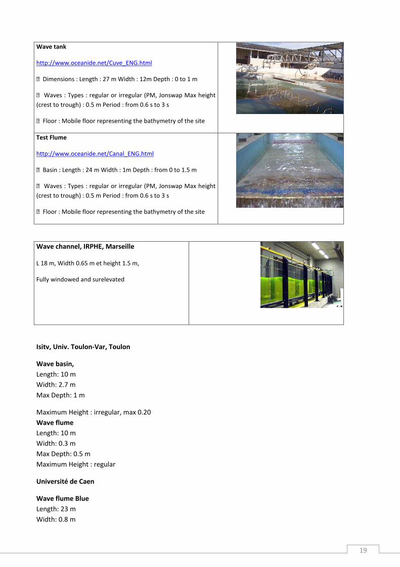
Wave tank
http://www.oceanide.net/Cuve_ENG.html
Dimensions : Length : 27 m Width : 12m Depth : 0 to 1 m
Waves : Types : regular or irregular (PM, Jonswap Max height
(crest to trough) : 0.5 m Period : from 0.6 s to 3 s
Floor : Mobile floor representing the bathymetry of the site
Test Flume
http://www.oceanide.net/Canal_ENG.html
Basin : Length : 24 m Width : 1m Depth : from 0 to 1.5 m
Waves : Types : regular or irregular (PM, Jonswap Max height
(crest to trough) : 0.5 m Period : from 0.6 s to 3 s
Floor : Mobile floor representing the bathymetry of the site
Wave channel, IRPHE, Marseille
L 18 m, Width 0.65 m et height 1.5 m,
Fully windowed and surelevated
Isitv, Univ. Toulon-Var, Toulon
Wave basin,
Length: 10 m
Width: 2.7 m
Max Depth: 1 m
Maximum Height : irregular, max 0.20
Wave flume
Length: 10 m
Width: 0.3 m
Max Depth: 0.5 m
Maximum Height : regular
Université de Caen
Wave flume Blue
Length: 23 m
Width: 0.8 m

20
Max Depth: 1 m
Maximum Height : Hs = 0.4 irregular
Wave flume Orange
Length: 18 m
Width: 0.5 m
Max Depth: 0.5 m
Velocity / Discharge: 0.8 m/s
Maximum Height : H = 0.2 regular
Spain :
2D Wave flume, CIEMLAB (Canal d’Investigació i Experimentació
Marítima), UPC (Universitat Politècnica de Catalunya) Barcelona
http://ciemlab.upc.edu/facilities/ciem-1/tripticcanalang.pdf
Dimensions : 100 m length, 3 m width and 5 m depth
The usual working scales are between 1:20 and 1:2, or even prototype
scale.
Windows and an optical test section along the flume offer a unique
capability for non-intrusive optical observations for a wide range of
experimental arrangements close to real scale.
Wave generation : controlled wave generation is achieved by a wedge-
type wave paddle, particularly suited for intermediate depth waves.
Maximum Height : Hs = 0.80 irregular/ Hs = 1.5 regular
Period: 1.5s < T < 9.5s
A PC-based active absorption system, allows running tests for wave series
as long as required without the effect of spurious model induced
reflections. This is an essential feature for testing highly-reflective
structures (such as surface-piercing structures) or for the analysis of
equilibrium shapes in beach profiles (particularly for long-duration
accretive sequences).
Usual applications :
1. Structural stability analyses
2. Structure functional-hydrodynamic analyses (run-up, run-down, overtopping, reflection and transmission).
3. Beach profile morphodynamics.
4. Wave beach structure interactions (scouring, fluxes through and above the structure, modified profile
morphodynamics).
5. Wave hydrodynamics.
6. Floating structures such as fish cages, floating breakwaters, buoys, energy extracting devices …

21
INHA (Applied Hydrodynamics Institute), Barcelona
Private laboratory for hydraulic test of port and coastal engineering. http://www.inha.es/en/medios-
materiales
Three dimensional wave basin
Dimensions: 27.6x22.5x1.2 metres
Some of the typical test carried out in the wave basin are:
• Breakwater and marine structure stability and overtopping.
• 3D wave forces, pressures and movements.
• Port resonance and long waves.
• Moored ship response.
• Sea bed and coastal evolution.
Two dimensional wave flume
Dimensions: 52.0x1.8x2.0 metres.
The type of test that are usually performed in the wave flume are
as follows:
• 2D stability and overtopping of breakwaters and marine
structures.
• 2D wave forces, pressures and motions.
• Analysis of wavw reflection and transmission.
• Beach profile evolution.
• Motions and stability analysis of floating structures.
Politec. Univ.Valencia :
Wave channel 1.2 m width
Length: 30 m
Width: 1.2 m
Max Depth: 1.2 m
Maximum Height Type: Hs = 0.40 irregular
Wave Channel with wind generation capabilities up to 10 m/s
Wave tank 15 x 1.5 m
Length: 15 m
Width: 7.5 m
22
Max Depth: 0.5 m
Surface: 112.5 m²
Maximum Height : Hs = 0.15 irregular
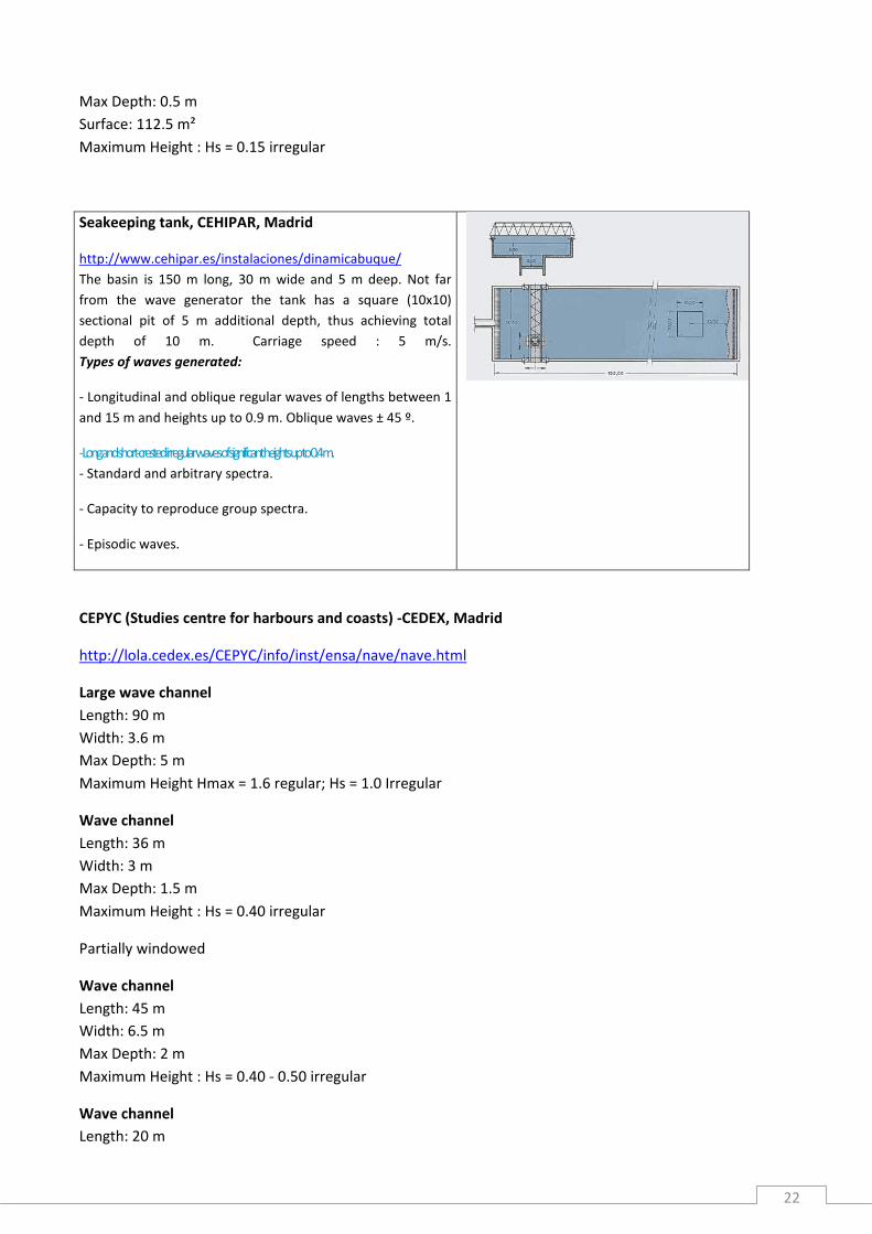
Seakeeping tank, CEHIPAR, Madrid
http://www.cehipar.es/instalaciones/dinamicabuque/
The basin is 150 m long, 30 m wide and 5 m deep. Not far
from the wave generator the tank has a square (10x10)
sectional pit of 5 m additional depth, thus achieving total
depth of 10 m. Carriage speed : 5 m/s.
Types of waves generated:
- Longitudinal and oblique regular waves of lengths between 1
and 15 m and heights up to 0.9 m. Oblique waves ± 45 º.
- Long and short-crested irregular waves of significant heights up to 0.4 m.
- Standard and arbitrary spectra.
- Capacity to reproduce group spectra.
- Episodic waves.
CEPYC (Studies centre for harbours and coasts) -CEDEX, Madrid
http://lola.cedex.es/CEPYC/info/inst/ensa/nave/nave.html
Large wave channel
Length: 90 m
Width: 3.6 m
Max Depth: 5 m
Maximum Height Hmax = 1.6 regular; Hs = 1.0 Irregular
Wave channel
Length: 36 m
Width: 3 m
Max Depth: 1.5 m
Maximum Height : Hs = 0.40 irregular
Partially windowed
Wave channel
Length: 45 m
Width: 6.5 m
Max Depth: 2 m
Maximum Height : Hs = 0.40 - 0.50 irregular
Wave channel
Length: 20 m
23
Width: 1.2 m
Max Depth: 0.8 m
Maximum Height : Hs = 0.25 irregular
Partially windowed
Wave channel
Length: 100 m
Width: 1 m
Max Depth: 1.5 m
Maximum Height : Hs = 0.40 irregular
Multidirectional wave tank
Length: 26 m
Width: 34 m
Max Depth: 1.6 m
Velocity / Discharge: 0.2 m3/s
Maximum Height : Hs = 0.58 irregular
Large wave channel, Politec. Univ.Coruńa, Coruńa,
Length: 70 m
Width: 3 m
Max Depth: 3 m
Maximum Height : Hs = 1.20 irregular
Active Reflection Absorption System
CEHINAV (Grupo de Investigación del Canal de Ensayos Hidrodinámicos) / ETSIN (Higher Technical School
of Naval Architecture and Ocean Engineering) - UPM (Politec. Univ. of Madrid)
Towing/Seakeeping tank :
Dimensions of 56 meters in length, 3.8m. wide, and 2.2m. of depth, its length was later increased to 100m.
carraige speed : 4,5 m/s.
It was projected in order that students of naval architecture would be put in contact with the methods of
experimentation in hydrodynamics. In addition to academic labour it is also used for the optimization of ship
hull design and forward resistance asessment.
Wave generator : generate regular waves of up to 0.2m height and periods of waves ranging form 0.5 to 2
seconds. With these waves it is possible to make studies of seakeeping of ships, mainly with forward and
stern seas.
Wave tank 32 x 34 m, Politec. Univ.Coruńa
Length: 32 m
24
Width: 34 m
Max Depth: 1.1 m
Velocity / Discharge: 300 l/s
Maximum Height : Hs = 0.40 irregular
Cantabria Univ. Santander
Wave tank 28.4 x 8.5 m
http://www.ihcantabria.com/WebIH/en/facilities/laboratories/multi_di
rectional_wave_tank.aspx
Length: 28.4 m
Width: 8.5 m
Max Depth: 1.2 m
Surface: 241.4 m²
Maximum Height : Hs = 0.3
Period: Tmax < 2s
Wave channel 2.0 m width
http://www.ihcantabria.com/WebIH/en/facilities/laboratories/wave_fl
ume.aspx
Length: 68.9 m
Width: 2 m
Max Depth: 2 m
Maximum Height : Hmax = 0.5 (interacting with current Hmax = 0.25)
Period: Tmax < 2.5s
Windowed 20 m
2.3 Water circulation flumes, per country
Norway :
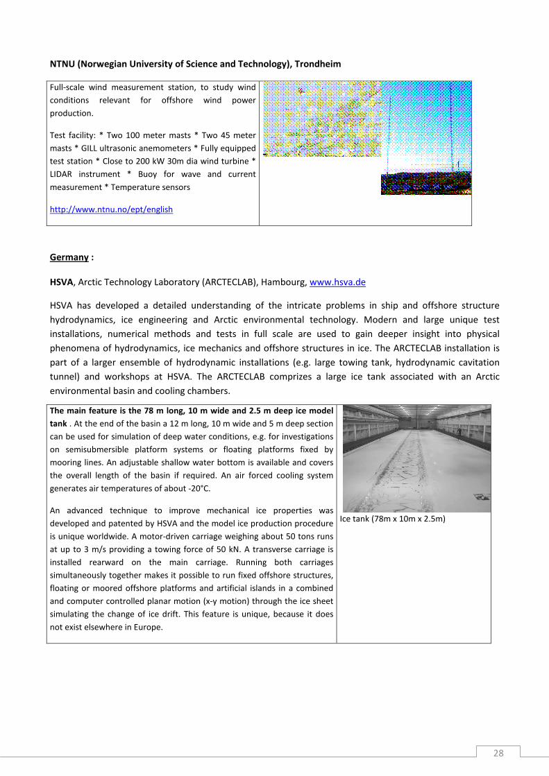
CWT (Circulation Water Tunnel)
Operated by the Department of Marine Technology (NTNU), in
co-operation with MARINTEK.
http://www.sintef.no/home/MARINTEK/Laboratories/Circulating-
Water-Tunnel/
Test facility dedicated to optical measurement techniques and
flow visualization. The tank's measurement section is completely
transparent and can be operated either with a free surface or the
lid closed. Laser-based techniques like PIV (Particle Image
Velocimetry) and LDV (Laser Doppler Velocimetry) allow non-
intrusive measurements of instantaneous 3D flow fields at high
temporal and spatial resolutions.

25
Test section: 2,50 x 0,61 x 0,61 m
Low turbulence level of 1% of free stream velocity.
Flow speed from 0,03 to 1 m/s. Also varying flow speed.
Fixed or free surface
Denmark :
Current Flume with a Carriage, DTU, Kgs. Lyngby, http://www.mek.dtu.dk/
The infrastructure is a medium-scale open current flume with dimensions 35 m (length), 3.0 m (width) and
1.0 m (depth). Water currents can be run with a maximum velocity of 1.5 m/s. The facility has a carriage
which facilitates to tow model structures with a maximum velocity of 2.1 m/s, enabling the flume to be used
as a towing tank. The carriage has dimensions of 3 m by 3 m (plan view). The same carriage (with a model
structure mounted onto the carriage) can be used to generate an oscillatory motion around the structure
model, with a maximum velocity of about 1.2-1.3 m/s, depending on the stroke of the motion. In this way,
wave-induced oscillatory flow around structures is simulated by moving the carriage back and forth in
otherwise still water. This proves extremely useful to generate large-amplitude oscillatory motions which
cannot be achieved in small- and medium-scale wave flumes. With this facility, flow around and forces on
cylindrical structures of dimensions of up to 0.5 m (in some instances, even larger) and subjected to steady
current and/or waves can be studied, e.g. offshore wind turbine foundations/towers, bridge piers, marine
pipelines, etc.
Services and type of research offered by the infrastructure :
· “Towing-tank” experiments of structure models such as offshore wind turbine towers / foundations
· Calibration of measuring instruments using the carriage facility up to 2.1 m/s velocity
· Current experiments with velocities up to 1.5 m/s, or using the carriage facility up to 2.1 m/s
· Wave-induced oscillatory flow experiments with velocities of up to 1.2-1.3 m/s
· Experiments on flow around structures including flow visualization and flow velocity measurements
· Pressure and force measurements on structure models

26
Germany :
Turbine Test rigs, University of Stuttgart, www.ihs.uni-stuttgart.de
The institute has a variable low head turbine test rig with an open
channel. This can be used for the investigation of LH-turbines for
tidal power plants as well as for turbines used in overtopping
wave energy devices. The applicable runner diameter for the
model turbines is approximately up to 300 mm. In addition in the
open channel small scale models of tidal current turbines can be
analysed. The test rig is equipped with the necessary sensors for
performance and efficiency measurements, also instrumentations
for flow measurements are available.
The performance tests can be carried out in steady state or in an
active controlled dynamic operation scheme.

27
2.4 Other land-based testing facilities, per country
(excluding towing tanks, cavitation tunnels, sloshing labs and other facilities only dedicated to ship design)
Norway :
Marine Structures Laboratory
Operated by MARINTEK
http://www.sintef.no/home/MARINTEK/Laboratories/Marine-
Structures-Laboratory/
The main activities in the laboratory are the testing of
structures, structural components and materials. Typical
problems involve fatigue testing, ultimate strength and
collapse testing. Experimental work is often combined with
analytical or numerical analysis.
Actuators: A range of servo hydraulic actuators for static and
dynamic testing, from 100 kN load capacity to a maximum
load/stroke of 4000 kN/1000 mm.
Control system: Several computerized systems for multi
actuator control, fatigue load simulation, data logging with
on-line reduction and analysis.
Small scale testing: Modular frame system which can be built
to accommodate specimens and structural models with a
wide range of shapes and sizes, under un axial or multi axial
loading, and with load capacities up to 4000 kN.
Full scale testing: Dynamic test rigs for static, dynamic and
fatigue testing of slender marine structures. The dimension of
the test specimen are typically15m flange to flange, and
applied loads include internal pressure, dynamic bending
(±30°) and tension (3000 kN).
28
NTNU (Norwegian University of Science and Technology), Trondheim
Full-scale wind measurement station, to study wind
conditions relevant for offshore wind power
production.
Test facility: * Two 100 meter masts * Two 45 meter
masts * GILL ultrasonic anemometers * Fully equipped
test station * Close to 200 kW 30m dia wind turbine *
LIDAR instrument * Buoy for wave and current
measurement * Temperature sensors
http://www.ntnu.no/ept/english
Germany :
HSVA, Arctic Technology Laboratory (ARCTECLAB), Hambourg, www.hsva.de
HSVA has developed a detailed understanding of the intricate problems in ship and offshore structure
hydrodynamics, ice engineering and Arctic environmental technology. Modern and large unique test
installations, numerical methods and tests in full scale are used to gain deeper insight into physical
phenomena of hydrodynamics, ice mechanics and offshore structures in ice. The ARCTECLAB installation is
part of a larger ensemble of hydrodynamic installations (e.g. large towing tank, hydrodynamic cavitation
tunnel) and workshops at HSVA. The ARCTECLAB comprizes a large ice tank associated with an Arctic
environmental basin and cooling chambers.
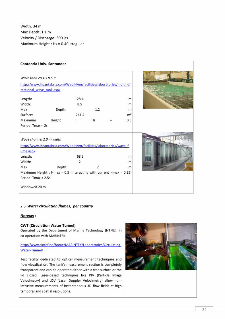
The main feature is the 78 m long, 10 m wide and 2.5 m deep ice model
tank . At the end of the basin a 12 m long, 10 m wide and 5 m deep section
can be used for simulation of deep water conditions, e.g. for investigations
on semisubmersible platform systems or floating platforms fixed by
mooring lines. An adjustable shallow water bottom is available and covers
the overall length of the basin if required. An air forced cooling system
generates air temperatures of about -20°C.
An advanced technique to improve mechanical ice properties was
developed and patented by HSVA and the model ice production procedure
is unique worldwide. A motor-driven carriage weighing about 50 tons runs
at up to 3 m/s providing a towing force of 50 kN. A transverse carriage is
installed rearward on the main carriage. Running both carriages
simultaneously together makes it possible to run fixed offshore structures,
floating or moored offshore platforms and artificial islands in a combined
and computer controlled planar motion (x-y motion) through the ice sheet
simulating the change of ice drift. This feature is unique, because it does
not exist elsewhere in Europe.
Ice tank (78m x 10m x 2.5m)

29
A smaller tank for environmental studies and experiments under cold
conditions which is unique in Europe. This basin is 30 m long, 6 m wide and
1.2 m deep. The bottom and sidewalls are sealed with a special oil resistant
coating. Air temperature can be cooled down to about –15°C, allowing the
simulation of typical arctic ice conditions. In addition to the ice making
facilities, special features include current generators, wavemakers and
wind generators. An underwater video system allows visual observation
and documentation of scenarios underneath the ice cover. Special features
of this tank are: simulation of real arctic conditions, generation of
propagating waves, current and wind.
The tank is suitable to perform a wide range of investigations including: a)
fundamental research in ice physics and arctic marine biology/chemistry, b)
study of sedimentological processes, penetration and distribution of oil in
the crystal structure of ice, study of biodegradation of oil polluted ice and
weathering of oil, c) simulation of oil spill scenarios in ice covered water,
development and testing of
new oil spill combat techniques.
Wave induced pancake formation
Cold room, which houses rare and unique sophisticated equipment and
testing machines (e.g. compressive strength testing machine, fracture
toughness apparatus, friction testing apparatus, shear apparatus and
universal stage for ice crystallographic investigations, etc.). Refrigerated
storage facilities for ice specimen are provided. The investigation of
mechanical ice properties is a standard procedure and includes the
determination of: flexural ice strength (in-situ), compressive ice strength,
elastic modulus, fracture toughness, stratigraphical ice texture
investigation, determination of grain sizes, friction coefficient, water
density, ice density, salinity of water and ice samples.
Fracture Toughness Test
AWI hyperbaric pressure tank,
http://www.awi.de/en/research/deep_sea/deep_sea_technology/pressure_tank/
The AWI hyperbaric pressure tank was originally developed to
test the properties of oxygen sensors for in situ experimentation
in the deep sea.
The tank has a maximum pressure rate of 600 bar, corresponding
to a water depth of 6,000 m. The available volume is 13 litres, the
temperature is adjustable from 2 to 25°C.
The tank is also used by other research groups for testing
different items of deep-sea equipment, and for biological
investigations, e.g. microbiological incubation experiments.

30
Netherlands :
Stichting Deltares (locations : Delft, Marknesse) :
Rotating Annular Flume. This Flume consists of a circular channel
with a mean diameter of 2.1 m
and a channel width of 0.2 m. The Flume and complementary
facilities are well suited to carry out
detailed studies on the various processes which cohesive sediments
undergo in fresh and salty
waters, including the direct measurement of bottom shear stress.
This installation is unique for its
hydraulic loads, its instrumentation and the possibility to carry out
tests with bio-chemical or polluted
sediments in a temperature controlled environment.
Water&Soil Flume. The facility is 2.5 m deep, 50 m long and 5.5 m
wide and can, because of its
large flow conditions, be used for virtually any water/soil-research
project with a wide variety of soil
types such as silt, sand, clay and rock, which is unique in Europe.
GeoCentrifuge. The GeoCentrifuge has a 2.0 m long, 1.0 m wide
and 1.0 m high model container that can be accelerated up to 300
times the normal gravity. This allows performing scale model
research at the same stress level as in prototype, which is
important to study water-soil-structure
interaction. Hydraulic actuators simulate external forces and it can
be equipped with a wave board. The lab can produce specific soil
models.
31
UK :
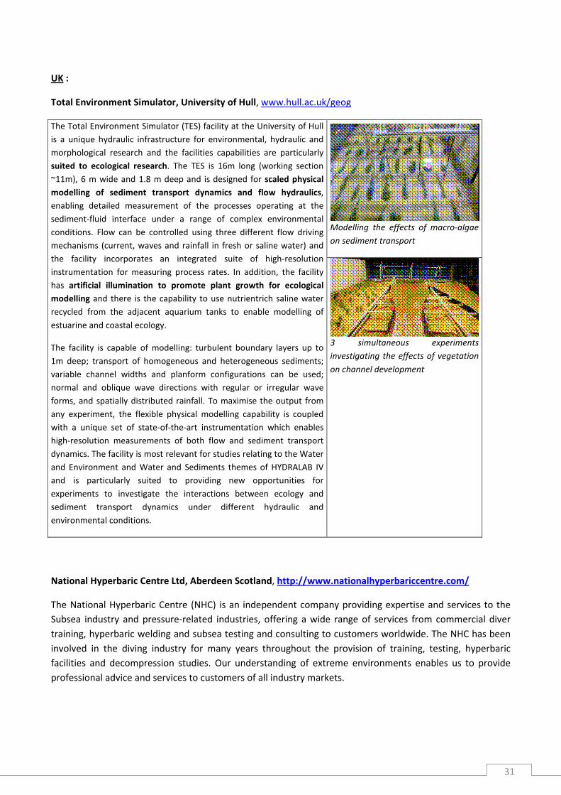
Total Environment Simulator, University of Hull, www.hull.ac.uk/geog
Modelling the effects of macro-algae
on sediment transport
The Total Environment Simulator (TES) facility at the University of Hull
is a unique hydraulic infrastructure for environmental, hydraulic and
morphological research and the facilities capabilities are particularly
suited to ecological research. The TES is 16m long (working section
~11m), 6 m wide and 1.8 m deep and is designed for scaled physical
modelling of sediment transport dynamics and flow hydraulics,
enabling detailed measurement of the processes operating at the
sediment-fluid interface under a range of complex environmental
conditions. Flow can be controlled using three different flow driving
mechanisms (current, waves and rainfall in fresh or saline water) and
the facility incorporates an integrated suite of high-resolution
instrumentation for measuring process rates. In addition, the facility
has artificial illumination to promote plant growth for ecological
modelling and there is the capability to use nutrientrich saline water
recycled from the adjacent aquarium tanks to enable modelling of
estuarine and coastal ecology.
The facility is capable of modelling: turbulent boundary layers up to
1m deep; transport of homogeneous and heterogeneous sediments;
variable channel widths and planform configurations can be used;
normal and oblique wave directions with regular or irregular wave
forms, and spatially distributed rainfall. To maximise the output from
any experiment, the flexible physical modelling capability is coupled
with a unique set of state-of-the-art instrumentation which enables
high-resolution measurements of both flow and sediment transport
dynamics. The facility is most relevant for studies relating to the Water
and Environment and Water and Sediments themes of HYDRALAB IV
and is particularly suited to providing new opportunities for
experiments to investigate the interactions between ecology and
sediment transport dynamics under different hydraulic and
environmental conditions.
3 simultaneous experiments
investigating the effects of vegetation
on channel development
National Hyperbaric Centre Ltd, Aberdeen Scotland, http://www.nationalhyperbariccentre.com/
The National Hyperbaric Centre (NHC) is an independent company providing expertise and services to the
Subsea industry and pressure-related industries, offering a wide range of services from commercial diver
training, hyperbaric welding and subsea testing and consulting to customers worldwide. The NHC has been
involved in the diving industry for many years throughout the provision of training, testing, hyperbaric
facilities and decompression studies. Our understanding of extreme environments enables us to provide
professional advice and services to customers of all industry markets.

32
A testing and trials facility enabling subsea equipment
and housings to be hydrostatically tested down to
3,000 metres. In addition, diving training and services
are available - including subsea familiarisation
programmes.
Hydrostatic pressure testing to 3,000 metres. Vessel
sizes up to 3 x 8 metres.
Open water test tank. 8 metres deep by 12 metres in
diameter, complete with air diving facility and work
area.
Training programmes for various diving disciplines,
including Subsea Familiarisation Programmes - which
can include practical diving.
France :
Coriolis rotating platform
Operated by CNRS Grenoble
The « Coriolis » rotating platform, equipped with a tank 13 m in diameter
and 1.2 m in height, is the largest turntable in the world dedicate to the
modeling of geophysical fluid dynamics. Its total weight is 150 tons and it
supports an extra load of 150 tons. Its rotation period can be set with high
stability between 18 and 1000 s and can be modulated to generate
permanent or oscillating circular flows, so to simulate tidal effects for
instance. It can be filled with homogeneous or density stratified water.
Stratification is made by filling the tank with a computer controlled
mixture from two underground tanks with specified salinity and
temperature. Various fixed or moving obstacles can be installed on
demand (transverse channel, annular shelf, oscillating plates, towed
cylinder, cylindrical plunger …). All the instruments, including lasers and
computers, stay on the platform, where electricity, water and computer
network are available, like in an ordinary laboratory. Researchers can stay
on the platform during rotation.

33
Hyperbaric tanks, IFREMER Brest
http://www.ifremer.fr/metri/pages_metri/infrastructure/hyperbaric.htm
Operator : Ifremer
The hyperbaric testing tanks allow the immersion simulation up to 10000
metres. Due to their dimensions (1 metre in diameter – 2 metres in
height), capabilities and associated means, they are unique in Europe.
They can be filled with fresh water or natural sea water and the
temperature and the level of dissolved gas can be regulated
The hyperbaric testing tanks have the following characteristics:
Tanks type
Characteristics
1000 bar
ACB
2400 bar 1000 bar
TDI
600 bar
EM
Max. Pressure 1000 bar 2400 bar 1000 bar 600 bar
Useful height 2 m 2,1 m 1,2 m 1,65 m
Useful diameter 1 m 0,535 m 0,3 m 0,3 m
Pressure cycling Yes Yes Yes Yes
Temperature Ambient to
2°C
Ambient to
55°C
From 2°C
to 70°C
From 2°C
to 55°C
Compressed
fluid
Fresh
water
Fresh
water
Fresh
water
Fresh/Sea
water

34
Materials and Structures Lab, IFREMER Brest
http://www.ifremer.fr/metri/pages_metri/infrastructure/materials.htm
Operator : Ifremer
Equipment is available for accelerated aging of materials in natural sea water,
with vessels at temperatures from up to 90°C. A natural aging site in the Brest
Estuary is also available. These facilities provide the possibility to study long
term durability and the influence of environmental degradation.
Complementary equipment (UV aging chamber, hydrostatic pressure
chambers) covers other environmental parameters.
Mechanical test equipment includes a static and fatigue test frames. The
largest, 10 meters long with a 100 ton capacity, has been extensively used in
studies for anchoring of floating offshore platforms. The machine can be
directly computer controlled using data files either from mooring line
simulations or measurements at sea. Samples can be tested wet or dry. Smaller
20 Ton and 1 Ton capacity static machines are also available.
Fatigue testing equipment includes three test frames up to a capacity of 25
tons. All can test samples in circulating natural sea water. Specific tests can also
be set up using hydraulic rams and custom test frames.
A range of equipment for physico-chemical analysis (FTIR, DSC, DMA, TGA,
SEM…) is also available. This can be used to both understand aging mechanisms
and to help to plan valid accelerated test programmes.-
Flexural fatigue test on
composite in natural sea
water
Large IRPHE/IOA wind-wave facility, IRPHE, Marseille
Length: 40 m
Width: 2.6 m
Max Depth: 1 m
Velocity / Discharge: 0.5 - 14 m/s wind; 0.1 m/s current
Maximum Height : regular/irregular
For Interactions Ocean Atmosphere : enable to generate
simultaneously mechanical waves and an air flow
Impact Tower, Ecole Centrale de Nantes, Nantes
Length: 5 m
Width: 4 m
Max Depth: 4 m
Racetrack flume, Sogreah, Pont de Claix
Sedimentological flume
Length: 18 m
Width: 0.5 m
Max Depth: 0.6 m
Velocity / Discharge: 0.6 m/s

35
Spain
Laboratory-Workshop of oceanographic instrumentation, cruises and sensors calibration
ICCM (Instituto Canario de Ciencias Marinas),Canarias
http://iccmoceanography.com/index.php?option=com_content&view=article&id=42&Itemid=11
Instrumentation :
- NAS-2E/NAS-3X nutrient sensors (7 units)
- Idronaut CTD (Mod.Seven-316), and its deck unit (Mod. MK
Deck Unit)
- SIS CTD (Mod. 1000plus)
- GO Rosetta (Mod 1018)
- Niskin bottles Mod 1010( 2,5/5/10 litres). Several units
- Niskin bottles Mod. Go-Flow. Several units
- XBT/XCTD probes launching gun Sippican (several). Deck unit
for probes Mod. Mk12 (2 units) and Mk21 (1 unit).
- Acoustic releaser MORS. Mod. AR661 B2S (2 units), with its
deck unit Mod. TT-300_A(1 unit).
2.5 In-situ test sites, per country
(excluding manoeuvring basins for ship models)
Denmark :
Nissum Bredning Test Site, Helligso, owner : Nordisk Folkecenter for Vedvarende Energy, operator : Aalborg
University , www.civil.aau.dk
Brednign field test site situated in a 1 kW/m open sea
environment.
The test field offers grid connection, a mooring pile and an
access bridge reaching 150 meter out into the broads.
The test site and the operators are has a record of participating
in testing more than 30 different devices during the 6 years life
time of the instrumented test site. Two well known devices who
have been extensively tested are Wave Dragon and Wave Star.

36
Germany :
Offshore field test facilities, North Sea, Fraunhofer Gesellschaft - IWES BHV,
http://www.iwes.fraunhofer.de
The Fraunhofer IWES in Bremerhaven is currently operating several
offshore field test facilities for testing materials and components for
offshore renewable energy devices of all kind. As there are at the
moment: Lighthouse “Alte Weser”, Island of Helgoland Island of Sylt,
River “Jade”, Lighthouse “Hoher Weg”. All this locations, spread in the
German North Sea, differ very much concerning the biological stress
and the mechanical loads applied on any kind of sample. For this
reason we are able to test the resistivity of the samples against the
marine environment and possible damages by all kind of
environmental loads.
In addition to these offshore field test facilities we are operating an
environmental test chamber in the Fraunhofer IWES, which is
designed to meet precise temperature and humidity controlled
environmental conditions for testing a wide range of products in a
shortened period of time. The test chamber is a unique facility for
experimental testing of materials (e.g. varnish, coatings), sensor
systems (e.g. strain or acceleration gauges) and their applications
under various environmental conditions. Different climate tests can be
combined with static and dynamic loads in the form of bending stress
in one test run to achieve best results. Via this chamber it is possible
to test 12 samples simultaneously with a maximum size of 500x200x4
mm. Thus affixed sensors or coatings are exposed to accelerated life
tests.
Lighthouse “Alte Weser”

37
Netherlands :
Tidal Testing Centre Den Oever, Stichting Tidal Testing Centre, www.tidaltesting.nl
The Tidal Energy Testing Centre in Den Oever, provides an excellent opportunities for Tidal Energy Testing.
Water flows range from 0 to 4,5 m/sec, depending on the tide. The facility is using an existing sluice, which
basic function is to discharge water from the IJsselmeer to the Waddenzee, 2 times per day. In total, 32
identical sluices are present, of which a limited number can be used for testing purposes, given that required
permits are in place. This basic function of the sluices always remains dominant; testing equipment therefore
has to be placed in a way that it can be easily removed or lifted in case of emergency.
Testing facilities available are a feed-in electrical grid-connection, with a capacity of 160 kVA, if needed scalable
to higher kVA. Equipment for on-line 3D ADCP flow measurements are available
on a rental basis, providing a detailed flow profile of the sluice. Data acquisition services are available, data is
accessible via the network of the Tidal Testing Centre. Daily flow prediction available, scheduling options for
opening/closing of sluice. When the sluice is closed, there is no water flow, which enables preparation and
inspection activities under calm conditions.
The size of one sluice is 16 m wide and 4,2 m depth. The sluice has a very suitable size for ‘intermediate scale’
testing of offshore devices (best practice for Tidal Testing is approx. 1:3 scale testing).
Also it is suitable for 1:1 scale testing of small tidal power units.
Flume characteristics are: Full cycle (0 - max - 0) one direction operation during ca. 3 hours. There are 2 cycles a
day.

38
UK :
South West Mooring Test Facility (SWMTF), Falmouth Bay, Cornwall, operator : University of Exeter,
http://www.exeter.ac.uk/news/featurednews/title,17603,en.php
South West Mooring Test Facility (SWMTF) will be located in
Falmouth Bay, Cornwall, UK, near the Manacles rocks, just
south of the mouth of the Helford River. The buoy is fully
equipped with load cells, motion sensors and other
instrumentation to test a variety of catenary and taut
mooring arrangements. It will transmit data directly to the
shore and will allow, for the first time, comprehensive
evaluation of mooring systems under real sea conditions.
Installation and survey support will be provided.
The specification of the facility are as follows:
Installation location:
Water depth: 27m
Tidal variation: 5.4m
Significant wave height: 3.5m
Surface current: 0.8m/s
Principle hardware for the mooring test facility includes:
a) Environmental monitoring instrumentation
ADCP wave/current profiler(s) (wave and current
measurement system), weather station/wind
instrumentation.
b) Response and loading instrumentation
Motion packed measuring 6-degree of freedom, DGPS
system, in-line mooring load cells, tri-axis load cells,
anchor/ADCP positioning system.
Data acquisition/radio communication
Data acquisition system, large capacity computer systems,
radio telemetry system .
European Marine Energy Centre (EMEC) , Orkney, Scotland, www.emec.org.uk
The European Marine Energy Centre (EMEC) Ltd was established to help the evolution of marine energy
devices from the prototype stage into the commercial market place. It provides grid-connected open sea
testing facilities for developers of wave and tidal energy devices and is currently developing smaller scale
‘nursery’ sites for both wave and tidal devices. These smaller scale sites are due for completion by February
2011: they will not be grid-connected, and will be available for a range of research and testing purposes.
39
The wave test site lies 2km off the west coast of Mainland Orkney, at
Billia Croo bay. There are currently four test berths in water depths of
approximately 50m, with a fifth planned for 2010 in deeper water, and an
inshore test site that may provide future grid connection in shallower
water. The existing four cables connect
the substation which lies just above the beach at Billia Croo to the centres
of the test berths.
The tidal test site is located to the west of Eday, one of Orkney’s North
Isles, in a tidal stream known as the Fall of Warness, which experiences
flow rates of 7.5 knots. The Fall is approximately 2km wide and 3.5 km
long. There are currently five test berths located in water depths of 25-
50m, with two further grid-connected berths planned for 2010. Cables
run from the substation which lies just above the beach, through the
beach, and along the seabed, terminating at the berth positions.
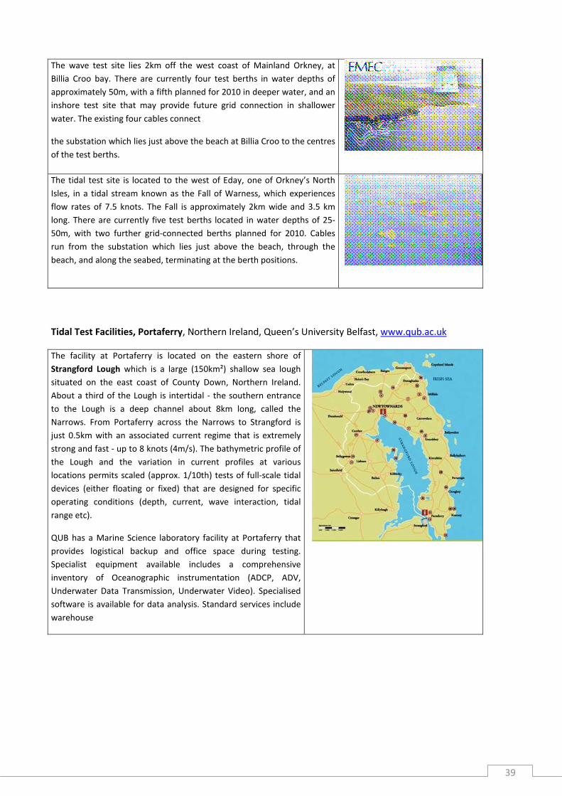
Tidal Test Facilities, Portaferry, Northern Ireland, Queen’s University Belfast, www.qub.ac.uk
The facility at Portaferry is located on the eastern shore of
Strangford Lough which is a large (150km²) shallow sea lough
situated on the east coast of County Down, Northern Ireland.
About a third of the Lough is intertidal - the southern entrance
to the Lough is a deep channel about 8km long, called the
Narrows. From Portaferry across the Narrows to Strangford is
just 0.5km with an associated current regime that is extremely
strong and fast - up to 8 knots (4m/s). The bathymetric profile of
the Lough and the variation in current profiles at various
locations permits scaled (approx. 1/10th) tests of full-scale tidal
devices (either floating or fixed) that are designed for specific
operating conditions (depth, current, wave interaction, tidal
range etc).
QUB has a Marine Science laboratory facility at Portaferry that
provides logistical backup and office space during testing.
Specialist equipment available includes a comprehensive
inventory of Oceanographic instrumentation (ADCP, ADV,
Underwater Data Transmission, Underwater Video). Specialised
software is available for data analysis. Standard services include
warehouse

40
Ireland :
Wave Energy Test Site, Galway Bay, Sustainable Energy Authority of Ireland, www.sei.ie/oedu
The two test sites are operated by Sustainable Energy
Ireland with support from the Marine Institute. The
Galway Bay test site is a benign quarter scale test site
for floating wave energy devices. This site is located on
the west coast of Ireland in Galway Bay off the Spiddal
coast. It is 37 Hectares in area and has a mean water
depth of 23m and a tidal range of 4m. Two devices
have been deployed on this site (Wavebob and Ocean
Energy Ltd.). A non-directional wave recording buoy
has been in situ since the test site’s inception in late
2005. Analysis of this data has shown that for quarter
scale devices the site can be highly energetic and
comparable to the Atlantic Ocean off the west coast of
Ireland.
Wave Energy Test Site, Belmullet, Co. Mayo, Sustainable Energy Authority of Ireland, www.sei.ie/oedu
The two test sites are operated by Sustainable Energy
Ireland with support from the Marine Institute.
The Belmullet test facility is under development and
will be grid connected and will enable developers to
monitor and assess the performance of devices. This
site will augment the quarter scale test facility at
Galway Bay. The site consists of berths at three
locations (a) nearshore 10m to 20m, (b) 50m depth
and (c) 100m depth. Environmental monitoring
projects have been deloyed at the site in 2009. For
ocean energy devices the nearshore site will be
available from 2011 with the 50m and 100m berths
available from 2012.

41
Portugal :
Full-scale OWC for real-sea testing of air turbines (100-700kW), Madalena, Azores, http://www.pico-
owc.net
The Pico OWC had been designed and built in the nineties as first
European grid-connected Pilot plant for OWC technology. The
structure is prepared for two fully sized turbine ducts for rated power
levels of up to 700kW, however only one of them has been
implemented. Together with the creation of WavEC, a recovery
project with moderate National funding was approved, and by 2005
the plant first delivered relevant amounts of power to the grid. Since
then, remaining technical issues have been solved to an extent that
the
original turbo-generation group can now generate at rated speeds,
being the next target autonomous operation.
It is now possible to prepare the second turbine lot for a modular and
variable test bed, allowing to test air turbines of industrially relevant
size in semi-controlled real-sea environment.
3. European integration and vision of the future
3.1 Major European projects
European integration in this domain is mainly supported by two FP7-I3 projects, one focused on hydraulic-
Hydrodynamic testing facilities for offshore engineering as for marine environment issues (HYDRALAB) and
one focused on Marine Renewable Energy (MARINET).
HYDRALAB IV : More than water, Dealing with the complex interaction of water with environmental
elements, sediment, structures and ice
o FP7-I3, 2011-2015
o Project web site : http://www.hydralab.eu/project_overview.asp
The co-ordinated and integrated approach of HYDRALAB aims at structuring the access to unique and costly
hydraulic and ice engineering research infrastructures in the European Research Area. The network of
HYDRALAB is unique in the hydraulic research community and has large experience in co-operating since its
start in 1997. It began by informing and co-ordinating the activities of the partners in HYDRALAB I and II, and
via strong collaboration in HYDRALAB III we will now realize further integration of our research services in
Europe in HYDRALAB IV. Over the course of 10 years our network has grown from 8 participants in 1997 to a
total of 30 partners and associated partners from 15 countries today.

42
Research in our infrastructures deals with complex questions regarding the interaction of water with
environmental elements, sediment, structures and ice and goes beyond just hydraulic research: hence we
have adopted the theme More than water, with the following elements:
• Water and environmental elements (focusing on ecology and biology)
• Water and sediment
• Water and structures
• Water and ice
MARINET : Marine Research Infrastructures Network for Energy Technologies
FP7-I3, april 2011-march 2015
Project web site : http://www.fp7-marinet.eu/
MARINET brings together a marine renewable energy testing network with 42 facilities from 28 partners
offering test facility access at no cost to research groups and companies. MARINET (Marine Renewables
Infrastructure Network) is a new initiative which aims to accelerate the development of marine renewable
energy technology by bringing together a network of specialist marine research facilities in various countries
to offer periods of marine renewable energy testing at no cost to applicants through European Commission
funding.
Applicants can avail of a range of infrastructures to test devices at any scale in areas such as wave energy,
tidal energy and offshore-wind energy or to conduct general tests on power take-off systems, grid
integration, moorings and environmental data. As well as offering funded test facility access, the MARINET
initiative will also implement common standards for testing, conduct research to improve testing capabilities
and provide training at various facilities in the network in order to enhance expertise in the industry.
European marine renewable energy test centres have formed this network in order to streamline the testing
process. By coordinating their unique capabilities and services, MARINET essentially provides a one-stop-
shop for marine renewable energy research and testing of devices and concepts in Europe and farther
afield. The aim is to advance marine renewables R&D at all scales - from small models and laboratory tests
through to prototype scales and open sea tests. Applicants can use different facilities to suit different stages
and scales of the technology’s development – results and techniques used at one facility will be recognised
by the next facility. MARINET brings together a network of personnel in the offshore marine renewable
energy sector with expertise at all scales of marine technology research and development.
The EC funding seeks to remove financial barriers for companies and research groups who may not qualify
for national grant aid for tests taking place outside their home state - it is generally necessary to test outside
the home state at some stage(s) of the development process in order to access unique facilities which do not
exist in the home state. Access is available to 42 facilities from 28 network partners spread across 11 EU
countries and 1 International Cooperation Partner Country (Brazil). Access is open to research groups and
companies of any size who wish to avail of these facilities. The two main conditions are that the majority of

43
the applicant group must work in Europe or a country associated to the European FP7 programme, and the
proposed facility must be outside the applicant’s home state. In total, over 700 weeks of access is available
to an estimated 300 projects and 800 external users. The initiative runs for four years until 2015, with at
least four calls for access applications.
Marinet trans national access : http://www.fp7-marinet.eu/access_facilities-available.html
3.2 Vision of the future
European integration still to complete
Some other important testing equipment, like hyperbaric tanks for sensors and instrumentation
qualification, are not integrated in an European network up to now,
Some marine sensors calibration labs are integrated in the FP7-I3 project JERICO- Coastal Observatories.
Norwegian Open Space Centre : a centre of marine technology knowledge for the future
Main elements of the future centre
The following paragraphs describe the most important elements of the infrastructure that will make up the
Ocean Space Centre:
o A flexible ocean space laboratory with complete ocean environmental modelling and deepwater
facilities, which will be an important tool for the development of future marine technology. This is
particularly important in view of the challenges presented by renewable ocean energy and oil and
gas production in very deep water and sensitive regions.
o A unique 3D flume tank for the study of the effects of complex flow conditions and internal waves
on slender marine structures.
o A combined towing tank and wave-generation basin, as well as a combined flume and cavitation
tunnel, designed to meet the challenges facing the shipping, fishing and aquaculture industries,
advanced marine operations under extreme weather conditions and the development of renewable
ocean energy resources.
o The arctic laboratory of the future: a wind tunnel with cold-climate facilities, a laboratory for the
study of oil in ice, and laboratories with the potential for testing marine operations under conditions
of icing in heavy seas.
o A groundbreaking design laboratory capable of dealing with future challenges at the interface
between structures and materials technology.
o Unique saltwater laboratories for the study of interactions between technology, biology and the
environment.

44
The sum total of all this will be an infrastructure for research and innovation without equal anywhere in the
world, and which will set new standards in marine technology. This will offer Norway new advantages and
help to provide a knowledge boost on a global scale.
http://www.sintef.no/upload/MARINTEK/Pilotstudy_OceanSpaceCentre_080210.pdf

45