lace must give to truck owner - summit racing...
TRANSCRIPT
South Bend Clutch 709 W. Jefferson Blvd. Mishawaka, IN 46545
Place
Postage
Here
“We Motivate The Shiftless”
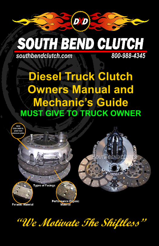
Diesel Truck Clutch Owners Manual and Mechanic’s Guide
MUST GIVE TO TRUCK OWNER
Always check parts for damage and
to make sure you have all
components needed before
installation begins. There will be a
separate check list for parts
provided with this clutch. You must
check to ensure that you have all
parts needed. If any
damage occurs during installation
due to skipping your parts
checklist, South Bend Clutch will
not be liable for parts, labor or
damage that may occur.
*Torque specifications will be
provided with parts list
Technical Bulletin From LazarSmith
Page 2
TIP: G56 disassembly and adjustment should only be attempted by a
trained, experienced professional.
Engine Operating Range Clutch and transmission durability are maximized by shifting at higher engine RPM – drivetrain stresses caused by high torque at low RPM are very hard on parts longevity - 500 HP at 3000 RPM is far easier on the clutch and transmission than 500 HP at 1500 RPM. Case in point: there’s no good reason to short-shift a Cummins common rail when loaded – even in stock form, the engine ECM will fuel through 3200 RPM, and the G56’s gear splits keep the engine well away from damaging low-RPM peak torque. Growling vibrations audible when heavily loading an aftermarket clutch with a CTD result from operating the engine close to the 9th order of torsional harmonic for that length crankshaft – not at all desirable, and an indication to downshift or reduce throttle position. TIP: The OEM DMF LUK clutch can be compared to a fusible link for the drivetrain to help move the truck through the warranty period.
Injectors Since turbodiesel common rails use pilot injection to help control en-gine combustion noise, unmasking the ignition pulses by deleting the DMF often makes those combustion events more audible – especially in the case of worn OEM fuel injectors or upgraded aftermarket injectors with higher-flowing tips; obviously, those stronger ignition pulses translate to more clutch and transmission noise. ECM tuning – the engine control module’s software that senses and dictates all engine operating parame-ters – has a significant effect on the severity of ignition pulses (combustion events) and therefore a large impact on how much noise is allowed by an aftermarket clutch. TIP: Custom ECM tuning (such as EFI Live) has many benefits besides reduced engine and drivetrain noise. High HP Applications Mile Lazar 2.26.13
23
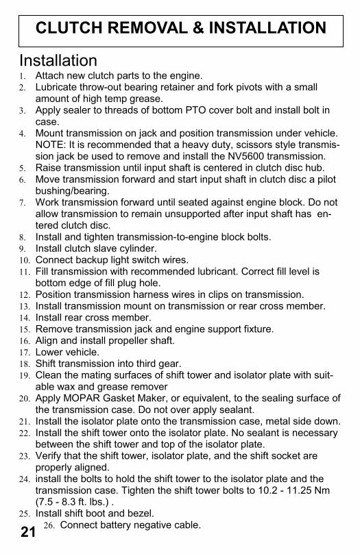
CLUTCH REMOVAL & INSTALLATION
Installation 1. Attach new clutch parts to the engine. 2. Lubricate throw-out bearing retainer and fork pivots with a small
amount of high temp grease. 3. Apply sealer to threads of bottom PTO cover bolt and install bolt in
case. 4. Mount transmission on jack and position transmission under vehicle.
NOTE: It is recommended that a heavy duty, scissors style transmis-sion jack be used to remove and install the NV5600 transmission.
5. Raise transmission until input shaft is centered in clutch disc hub. 6. Move transmission forward and start input shaft in clutch disc a pilot
bushing/bearing. 7. Work transmission forward until seated against engine block. Do not
allow transmission to remain unsupported after input shaft has en-tered clutch disc.
8. Install and tighten transmission-to-engine block bolts. 9. Install clutch slave cylinder. 10. Connect backup light switch wires. 11. Fill transmission with recommended lubricant. Correct fill level is
bottom edge of fill plug hole. 12. Position transmission harness wires in clips on transmission. 13. Install transmission mount on transmission or rear cross member. 14. Install rear cross member. 15. Remove transmission jack and engine support fixture. 16. Align and install propeller shaft. 17. Lower vehicle. 18. Shift transmission into third gear. 19. Clean the mating surfaces of shift tower and isolator plate with suit-
able wax and grease remover 20. Apply MOPAR Gasket Maker, or equivalent, to the sealing surface of
the transmission case. Do not over apply sealant. 21. Install the isolator plate onto the transmission case, metal side down. 22. Install the shift tower onto the isolator plate. No sealant is necessary
between the shift tower and top of the isolator plate. 23. Verify that the shift tower, isolator plate, and the shift socket are
properly aligned. 24. install the bolts to hold the shift tower to the isolator plate and the
transmission case. Tighten the shift tower bolts to 10.2 - 11.25 Nm (7.5 - 8.3 ft. lbs.) .
25. Install shift boot and bezel. 26. Connect battery negative cable.
21 2
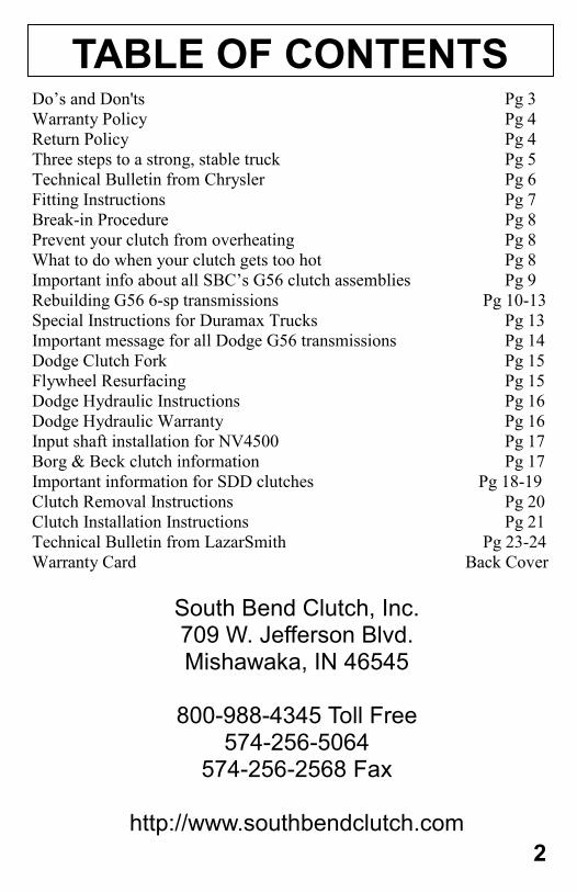
TABLE OF CONTENTS Do’s and Don'ts Pg 3
Warranty Policy Pg 4
Return Policy Pg 4
Three steps to a strong, stable truck Pg 5
Technical Bulletin from Chrysler Pg 6
Fitting Instructions Pg 7
Break-in Procedure Pg 8
Prevent your clutch from overheating Pg 8
What to do when your clutch gets too hot Pg 8
Important info about all SBC’s G56 clutch assemblies Pg 9
Rebuilding G56 6-sp transmissions Pg 10-13
Special Instructions for Duramax Trucks Pg 13
Important message for all Dodge G56 transmissions Pg 14
Dodge Clutch Fork Pg 15
Flywheel Resurfacing Pg 15
Dodge Hydraulic Instructions Pg 16
Dodge Hydraulic Warranty Pg 16
Input shaft installation for NV4500 Pg 17
Borg & Beck clutch information Pg 17
Important information for SDD clutches Pg 18-19
Clutch Removal Instructions Pg 20
Clutch Installation Instructions Pg 21
Technical Bulletin from LazarSmith Pg 23-24
Warranty Card Back Cover
South Bend Clutch, Inc. 709 W. Jefferson Blvd. Mishawaka, IN 46545
800-988-4345 Toll Free
574-256-5064 574-256-2568 Fax
http://www.southbendclutch.com
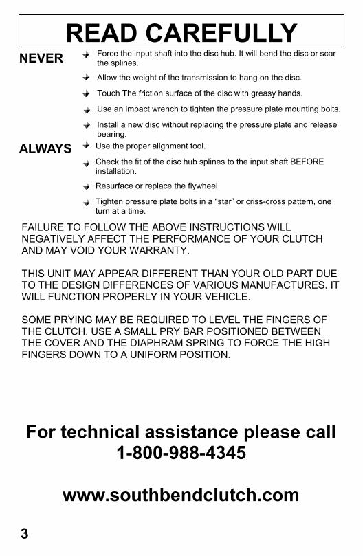
READ CAREFULLY NEVER Force the input shaft into the disc hub. It will bend the disc or scar
the splines.
Allow the weight of the transmission to hang on the disc.
Touch The friction surface of the disc with greasy hands.
Use an impact wrench to tighten the pressure plate mounting bolts.
Install a new disc without replacing the pressure plate and release bearing.
ALWAYS
FAILURE TO FOLLOW THE ABOVE INSTRUCTIONS WILL NEGATIVELY AFFECT THE PERFORMANCE OF YOUR CLUTCH AND MAY VOID YOUR WARRANTY. THIS UNIT MAY APPEAR DIFFERENT THAN YOUR OLD PART DUE TO THE DESIGN DIFFERENCES OF VARIOUS MANUFACTURES. IT WILL FUNCTION PROPERLY IN YOUR VEHICLE. SOME PRYING MAY BE REQUIRED TO LEVEL THE FINGERS OF THE CLUTCH. USE A SMALL PRY BAR POSITIONED BETWEEN THE COVER AND THE DIAPHRAM SPRING TO FORCE THE HIGH FINGERS DOWN TO A UNIFORM POSITION.
For technical assistance please call 1-800-988-4345
www.southbendclutch.com
Use the proper alignment tool.
Check the fit of the disc hub splines to the input shaft BEFORE installation.
Resurface or replace the flywheel.
Tighten pressure plate bolts in a “star” or criss-cross pattern, one turn at a time.
3
CLUTCH REMOVAL & INSTALLATION
Removal 1. Disconnect battery negative cable. 2. Shift transmission into Neutral. 3. Remove screws attaching shift boot to floor pan. Then slid boot
upward on the shift lever. 4. Remove the bolts holding the shift tower to the isolator plate
and transmission gear case. 5. Remove the shift tower and isolator plate from the transmission
gear case. 6. Raise and support vehicle. 7. Mark propeller shaft and axle yokes for alignment reference.
Use paint, scriber, or chalk to mark yokes. 8. Remove universal joint strap screws and remove straps. 9. Remove propeller shaft. 10. Disconnect and remove exhaust system as necessary. 11. Disconnect wires at backup light switch. 12. Support engine with adjustable safety stand and wood block. 13. If transmission is to be disassembled for repair, remove drain-
bolt at bottom of PTO cover and drain lubricant from trans. 14. Remove bolts/nuts attaching transmission to rear mount. 15. Support transmission with a transmission jack. Secure trans-
mission to jack with safety chains. NOTE: It is recommend that a heavy duty, scissors style transmission jack be used to re-move and install the NV5600 transmission.
16. Remove rear cross member. 17. Remove bolts attaching clutch slave cylinder to clutch housing.
Then move cylinder aside for working clearance. 18. Remove wire harness from clips on transmission. 19. Remove bolts attaching transmission clutch housing to the en-
gine block. 20. Slide transmission and jack rearward until input shaft clears
clutch disc and pressure plate. 21. Lower transmission jack and remove transmission from under
vehicle. 22. Remove clutch and flywheel from the engine and clean the
crankshaft flange.
20
in the transmission (and usually a combination of both) directly affect the
likelihood of noise when the engine is idling.
Due to the fact that we have had a vast amount of experience with the
late model G-56 transmissions, we have come to learn that the internal
components (especially the aluminum case) are prone to wear. In order to
reduce the risk of your system making noise after your new clutch is in-
stalled, YOU MUST INSPECT THE TRANMISSION.
A qualified transmission specialist needs to check the amount of play
in your input shaft. Even a small amount of movement could indicate a
problem, which will just get worse and could cause a catastrophic failure.
Occasionally, we hear people complain of noise while accelerating.
This is where the bad driving habits come in. We have come to realize
that some people (in order to conserve fuel) shift into the next gear too
soon. If the transmission is in too high a gear, at a low wheel speed, it
causes a lugging effect on the engine (we have all experienced this if we
were trying to shift into 2nd gear, but instead hit 4th). This lugging will
cause a backlash in the splined hubs of the clutch discs, and can cause an
unnecessary noise. This seems to be most apparent in the late model, alu-
minum cased transmissions. The solution is simple. Keep the RPM”s up
while shifting. This will prolong the life of the entire drivetrain.
We try to explain to our customers that they may need to adapt to the
new system. In other words, “you may need to change the way you
drive”. People don’t like to hear that. Remember, even though you may
not have had any noise before, the way you drove (along with your
power upgrades and loads) definitely attributed to the short life of the
DMF. You can’t make dramatic changes in your truck, without realizing
that you might need to make some changes in your behavior and your
expectations.
We feel that the most important thing we can provide to our custom-
ers, is a clutch that drives nice, and lasts. We have done just that. We
make every effort to improve our products as needs arise, and will con-
tinue to do so. We listen to our customer’s concerns and try to take them
all into consideration. This is the reason that we have been able to pro-
vide the best clutch in the industry…..hands down.
Keep calling. We want to hear from you!
IMPORTANT INFO FOR SDD CLUTCHES
CONTINUED FROM PAGE 18
19
RETURN POLICY
South Bend Clutch, Inc. warrants that our clutches are free from defects
in workmanship and material under normal use and service. The
obligation of SBC under this warranty is limited to repair or replacement
of the defective products, which falls within 12 months or 12,000 miles.
We will not be liable for losses that might be claimed as a result of the
failure of any part, nor shall we be liable for damages or injury to any
persons or property resulting from the misuse or improper installation of
any part subject to this warranty.
South Bend Clutch, Inc. reserves the right to examine all parts returned
for warranty claim to determine whether or not any such part has failed
because of a defect in material or workmanship. Our obligation under
this warranty shall be limited to repairing, replacing or crediting, at our
discretion, any part found to be defective.
The Limited Warranty will not be valid under the following express
conditions:
When proper break-in procedure was not followed. To receive proper
break-in procedure for your application please refer to page 8.
When flywheel was not replaced with new or resurfaced to
specification.
Clutches which have been alter, improperly installed, or damaged by
accident, negligence or misuse.
PRODUCTS USED FOR HIGH PERFORMANCE AND/OR RACING
PURPOSES, FOR WHICH THEY WERE NOT ORIGINALLY
ENGINEERED, WILL NOT BE COVERED.
WARRANTY POLICY
No product returned for warranty, repair, or replace-
ment will be accepted without a return authorization
number. Please call and speak to our warranty depart-
ment at 1-800-988-4345.
4
When upgrading your truck, you don’t want to leave anything out.
The first thing most people do is to modify their engine. Injectors, turbo-
chargers, programmers and fuel systems are all needed to boost the
power effectively.
Now that you have the desired horsepower and torque levels, your
next job is to upgrade your clutch (or automatic transmission) to be able
to handle the additional power. Choosing a clutch, which will transfer the
power without too much shock to the internal components of the trans-
mission, is an important thing to consider. Once the clutch is engaged,
the additional power is transferred beyond the transmission, to the rest of
the drive train.
This brings us to the third (often overlooked), and equally important
upgrade. Most people do not realize how the combination of extra power
and extra load can effect the rear end of the truck. There is an amazing
video on youtube (http://youtube/Pym_k8lAHok) that shows just how
much activity there is, as a truck accelerates. If you watch the video, you
will see a Dodge pick-up truck, with a bone stock diesel engine and auto-
matic transmission, as it takes off and shifts. Even with no load behind
the truck, you can see the rear-end housing and axle lash dramatically
every time the transmission shifts. As a result of this movement, the slip
yoke pulls out a good inch, from the transfer case. Now, imagine how
much movement you would have when you increase the horsepower and
use a manual transmission.
We often hear people complain that their truck “hops”, especially
when they are trying to back up a load. Their first reaction is to blame the
clutch, but what they are experiencing is massive amounts of axle lash.
There is an easy fix for this problem.
In the past, “Ladder Bars” were primarily associated with drag racing,
but they are back, in a big way. The addition of this simple item, will sta-
bilize your rear-end and virtually eliminate that annoying “hop” when
you’re trying to take off. It will also extend the life of your drive shaft,
rear end gears, and seals.
If you want your truck to run well, and last for years, don’t forget the
three steps in upgrading. 1. Engine 2. Clutch/Transmission 3. Rear-end
Stabilizers.
3 STEPS TO BUILDING A STABLE TRUCK
5
RE: South Bend Dual Disc clutches for Dodge & Ford diesel pick-up trucks
This notice is an attempt on our part to respond to some complaints
we have had about our products. Our goal is to try to help our customers
gain a better understanding of what goes on in their drive train when up-
grades are introduced, and how some simple changes in driving habits
can help.
When a gas engine runs, it has a smooth, uninterrupted rotation. When
a diesel engine runs, the opposite is true. A diesel has a pulsation, which
is caused by small, quick spikes in torque (4-8 times per revolution, de-
pending on how many cylinders the engine has). This causes a vibration,
most apparent at idle speeds, which needs to be dampened so that it is not
transferred to the transmission, causing the gears to “clatter” and make
noise.
When Dodge and Ford introduced the Dual Mass Flywheel (DMF)
they successfully dampened the vibration. The DMF worked well when
the engine ran at factory specifications, and when the towing limits were
not exceeded. As soon as these trucks started being used beyond the
OEM recommendations, problems started to occur.
Horsepower and torque upgrades, excessive towing loads and poor
driving habits caused the DMF to wear out and eventually fail. Keep in
mind that while it was wearing out, it was still dampening the vibration,
until it failed completely.
Because it became increasingly more common to use these trucks be-
yond their limitations, we were impelled to come up with a clutch system
that could, not only hold the extra torque, but would also provide a rea-
sonable amount of dampening.
We succeeded in doing that. However, there are some distinct differ-
ences between how our system operates, compared to the OEM design.
In order to make a clutch withstand dramatic increases in torque and
load, certain aspects of the system needed to be improved and strength-
ened. For example, the dampening springs in the clutch discs had to be
stronger, or they would fail just like the DMF. Our original design was
made too strong in that area, which caused some noise at idle. Our new
hub design has eliminated that problem in most trucks, without sacrific-
ing it’s capacity for torque. Keep in mind that noise is not always caused
by the clutch. The way that the engine runs, and the amount of wear
IMPORTANT INFO FOR SDD CLUTCHES
18
TECHNICAL BULLETIN FROM CHRYSLER
6
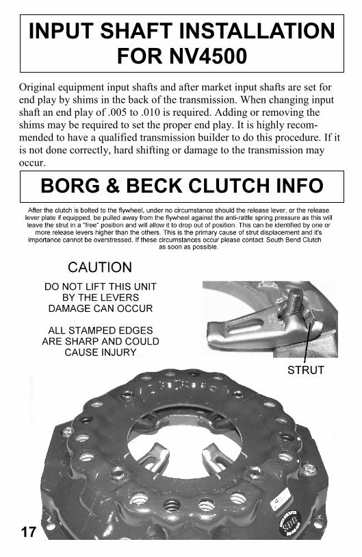
Original equipment input shafts and after market input shafts are set for
end play by shims in the back of the transmission. When changing input
shaft an end play of .005 to .010 is required. Adding or removing the
shims may be required to set the proper end play. It is highly recom-
mended to have a qualified transmission builder to do this procedure. If it
is not done correctly, hard shifting or damage to the transmission may
occur.
INPUT SHAFT INSTALLATION FOR NV4500
BORG & BECK CLUTCH INFO
17
FITTING INSTRUCTIONS INSTALLING YOUR NEW SOUTH BEND CLUTCH
Failure to observe these instructions when installing your South Bend Clutch will void any warranty.
1. Get it right the first time. It is vital to diagnose the cause of clutch malfunctions BEFORE it is
just assumed that the clutch needs to be replaced. If the system uses hydraulics or a cable to disengage the clutch, make sure they are operating properly. You can also check things like bearing free-travel or oil leaks to determine if the clutch actually needs to be removed
2. Once you’ve decided to replace the clutch, you need to be certain that the parts that have been supplied to you are indeed the right ones for your application. If you are unsure, con-tact your South Bend Clutch dealer (or call us directly), as fitting a clutch to the wrong appli-cation WILL void the warranty. Even bolting it on will classify the parts as used, and can end up costing you more.
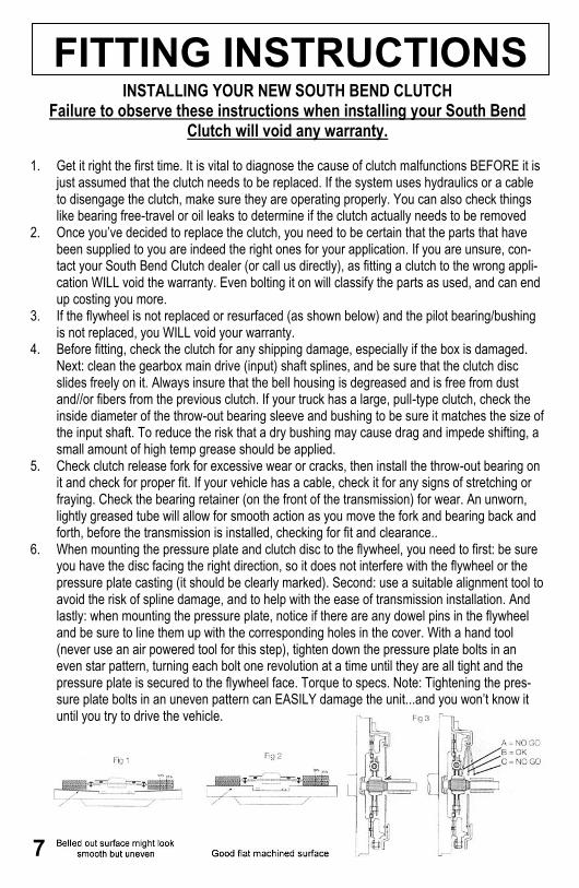
3. If the flywheel is not replaced or resurfaced (as shown below) and the pilot bearing/bushing is not replaced, you WILL void your warranty.
4. Before fitting, check the clutch for any shipping damage, especially if the box is damaged. Next: clean the gearbox main drive (input) shaft splines, and be sure that the clutch disc slides freely on it. Always insure that the bell housing is degreased and is free from dust and//or fibers from the previous clutch. If your truck has a large, pull-type clutch, check the inside diameter of the throw-out bearing sleeve and bushing to be sure it matches the size of the input shaft. To reduce the risk that a dry bushing may cause drag and impede shifting, a small amount of high temp grease should be applied.
5. Check clutch release fork for excessive wear or cracks, then install the throw-out bearing on it and check for proper fit. If your vehicle has a cable, check it for any signs of stretching or fraying. Check the bearing retainer (on the front of the transmission) for wear. An unworn, lightly greased tube will allow for smooth action as you move the fork and bearing back and forth, before the transmission is installed, checking for fit and clearance..
6. When mounting the pressure plate and clutch disc to the flywheel, you need to first: be sure you have the disc facing the right direction, so it does not interfere with the flywheel or the pressure plate casting (it should be clearly marked). Second: use a suitable alignment tool to avoid the risk of spline damage, and to help with the ease of transmission installation. And lastly: when mounting the pressure plate, notice if there are any dowel pins in the flywheel and be sure to line them up with the corresponding holes in the cover. With a hand tool (never use an air powered tool for this step), tighten down the pressure plate bolts in an even star pattern, turning each bolt one revolution at a time until they are all tight and the pressure plate is secured to the flywheel face. Torque to specs. Note: Tightening the pres-sure plate bolts in an uneven pattern can EASILY damage the unit...and you won’t know it until you try to drive the vehicle.
7
Free up the hydraulic line between the master and the slave (there are
a few zip ties holding it in place)
Remove the linkage from the pedal (a clip and a pin—careful with
the clip since it’s spring loaded and will try to hide)
While you’re on your back under the dash, unplug the clutch inter-
lock switch
Remove the clutch master cylinder from the firewall by unbolting the
bracket. Be careful fishing the assembly out of the truck, so you don’t
snag any wires and create other problems. Unbolt the slave cylinder.
Reinstall the new setup in reverse order.
Things to remember on the reinstall:
Leave the plastic strap on the slave cylinder until it is bolted in place.
The first time you push the pedal it will snap. This will prevent the
slave from over extending and will keep the plastic bushing in place
during assembly (and make sure you remove the old one)
Find a clear spot on the firewall to mount the master cylinder reser-
voir, when applicable, with supplied self tapping screws.
Start with a rod adjusted all the way in (between the master cylinder
and pedal) then adjust it out a couple of turns (compensate for thick
floor mats)
90 DAY WARRANTY ON HYDRAULICS
South Bend Clutch, Inc. warrants that our hydraulics are free from defects in workman-
ship and material under normal use and service. The obligation of SBC under this war-
ranty is limited to repair or replacement of the defective products, which fails within 90
days after sale (invoice date) South Bend Clutch, Inc. after inspection discloses to it’s
satisfaction that the hydraulic is defective. Buyer must not return the defective parts
without the consent of the seller. SBC shall not be liable for any special, direct, indirect,
incidental or consequential damages, including, but not limited to, claims for delay, loss
of profits, or for labor. No express warranties and no implied warranties either of mer-
chantability or fitness for any particular use or purpose or otherwise, other than that
expressly set forth above which are made expressly in lieu of all other warranties, shall
apply to clutch products sold by South Bend Clutch, Inc.
The Limited Warranty will not be valid if hydraulics have been altered,
improperly installed, or damaged by accident, negligence or
misuse.
DODGE HYDRAULIC INST.
HYDRAULIC WARRANTY
16

The best way to break-in your new clutch is stop and go
driving for 300-400 miles
Do not launch during break-in period
Do not ease into the clutch at high RPM
Do not slip the clutch for more than 2 seconds
Feramic friction material when heated to 1100F can run the
risk of welding to the adjacent friction plates. Use the follow-
ing steps to prevent this from happening.
3 sec rule. Don’t slip your clutch for more than 3 seconds at
high RPM
Don’t use the clutch to prevent rolling back on a hill
Engage the clutch as quickly as possible when taking off
from a complete stop
Follow all break-in procedures
Follow a few easy steps to lessen the damage if your clutch
gets too hot.
Hold the clutch pedal down for 10-15 seconds immediately
after over heating to allow cooling time
Continue driving your truck after over heating
If your clutch welds itself together try starting the truck
while in gear with your foot on the brake. This will often
times break it free. SBC is not responsible for any damage
These suggestions will only get you home. At this point the
clutch should DEFINITELY be removed for inspection
BREAK-IN PROCEDURE
PREVENT YOUR CLUTCH FROM OVERHEATING
WHAT TO DO WHEN YOUR CLUTCH GETS TOO HOT
8
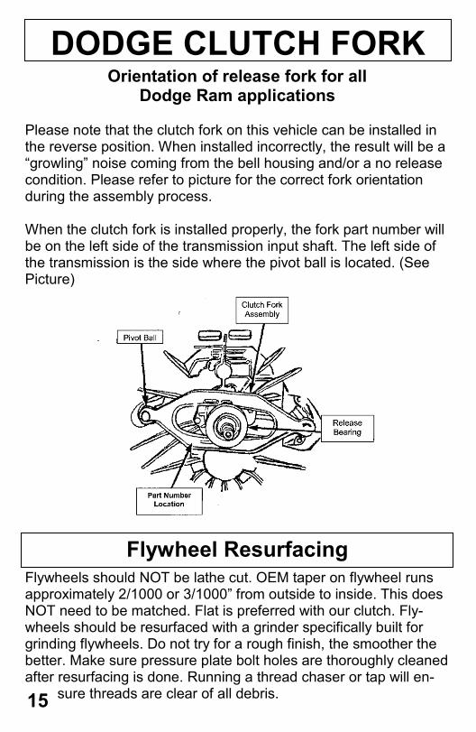
DODGE CLUTCH FORK Orientation of release fork for all
Dodge Ram applications
Please note that the clutch fork on this vehicle can be installed in the reverse position. When installed incorrectly, the result will be a “growling” noise coming from the bell housing and/or a no release condition. Please refer to picture for the correct fork orientation during the assembly process. When the clutch fork is installed properly, the fork part number will be on the left side of the transmission input shaft. The left side of the transmission is the side where the pivot ball is located. (See Picture)
Flywheel Resurfacing
Flywheels should NOT be lathe cut. OEM taper on flywheel runs approximately 2/1000 or 3/1000” from outside to inside. This does NOT need to be matched. Flat is preferred with our clutch. Fly-wheels should be resurfaced with a grinder specifically built for grinding flywheels. Do not try for a rough finish, the smoother the better. Make sure pressure plate bolt holes are thoroughly cleaned after resurfacing is done. Running a thread chaser or tap will en-
sure threads are clear of all debris. 15
In 2005, Chrysler re-designed their 6-speed, manual trans-
mission and clutch for the Dodge diesel pick-up trucks. Since
the inception of the Mercedes built G56 trans and the LUK de-
signed Dual Mass clutch system, Dodge owners have been ex-
periencing problems at an alarming rate, especially if the
power of the engine has been turned up, or the factory towing
limitations are exceeded.
Noise, vibration and slippage are common and obvious
symptoms of a system failure, resulting in the need for a new
clutch.
However, many people do not realize that the transmission
may be worn as well. Too often, the clutch is the only thing
that is replaced or upgraded. It is important to note that a failed
dual mass flywheel, and the vibration it creates, can also dam-
age the transmission regardless of how many miles are on it.
Our new clutch design has significantly increased the lon-
gevity and the capacity of the system, but that advantage will
not be realized if a worn transmission is installed behind it.
Overloading the drive-train can result in excessive wear of a
transmission in a relatively short amount of time. The alumi-
num casing of the G56 is prone to wear under [even] normal
conditions. Excessive end-play or movement of the input shaft,
caused by worn bearings or housings, is a very common and
often overlooked problem. This can result in a variety of
symptoms, such as noises, clutch release issues or pilot bearing
failure.
The installation of a worn transmission, which has not been
thoroughly inspected by a qualified professional, will void any
and all warranty on the clutch parts.
IMPORTANT INFO ABOUT ALL SBC’S G56 CLUTCH ASSEMBLIES
AND TRANSMISSIONS
9
When installing any of our single disc or SDD (Street Dual Disc) clutch kits, the flywheel, which has a built in crank spacer, can only be bolted to the bare crank shaft. When installing a competition double disc kit you must use the crank spacer provided. Any tin spacer that may be there needs to be removed.
ATTENTION
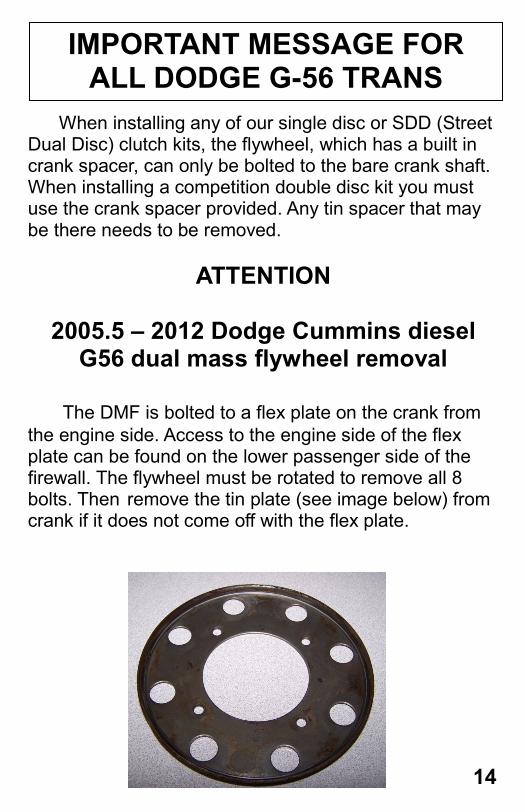
2005.5 – 2012 Dodge Cummins diesel G56 dual mass flywheel removal
The DMF is bolted to a flex plate on the crank from
the engine side. Access to the engine side of the flex plate can be found on the lower passenger side of the firewall. The flywheel must be rotated to remove all 8 bolts. Then remove the tin plate (see image below) from crank if it does not come off with the flex plate.
IMPORTANT MESSAGE FOR ALL DODGE G-56 TRANS
14
REBUILDING G56 6-SP TRANS
PAGE 1
10
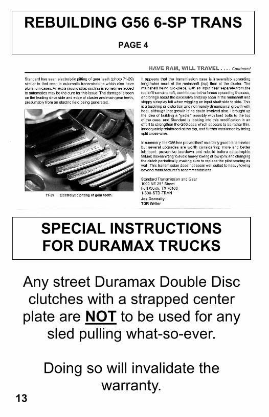
REBUILDING G56 6-SP TRANS
PAGE 4
13
SPECIAL INSTRUCTIONS FOR DURAMAX TRUCKS
Any street Duramax Double Disc clutches with a strapped center
plate are NOT to be used for any sled pulling what-so-ever.
Doing so will invalidate the
warranty.
REBUILDING G56 6-SP TRANS
PAGE 3
12
REBUILDING G56 6-SP TRANS
PAGE 2
11
REBUILDING G56 6-SP TRANS
PAGE 3
12
REBUILDING G56 6-SP TRANS
PAGE 2
11
REBUILDING G56 6-SP TRANS
PAGE 1
10
REBUILDING G56 6-SP TRANS
PAGE 4
13
SPECIAL INSTRUCTIONS FOR DURAMAX TRUCKS
Any street Duramax Double Disc clutches with a strapped center
plate are NOT to be used for any sled pulling what-so-ever.
Doing so will invalidate the
warranty.
In 2005, Chrysler re-designed their 6-speed, manual trans-
mission and clutch for the Dodge diesel pick-up trucks. Since
the inception of the Mercedes built G56 trans and the LUK de-
signed Dual Mass clutch system, Dodge owners have been ex-
periencing problems at an alarming rate, especially if the
power of the engine has been turned up, or the factory towing
limitations are exceeded.
Noise, vibration and slippage are common and obvious
symptoms of a system failure, resulting in the need for a new
clutch.
However, many people do not realize that the transmission
may be worn as well. Too often, the clutch is the only thing
that is replaced or upgraded. It is important to note that a failed
dual mass flywheel, and the vibration it creates, can also dam-
age the transmission regardless of how many miles are on it.
Our new clutch design has significantly increased the lon-
gevity and the capacity of the system, but that advantage will
not be realized if a worn transmission is installed behind it.
Overloading the drive-train can result in excessive wear of a
transmission in a relatively short amount of time. The alumi-
num casing of the G56 is prone to wear under [even] normal
conditions. Excessive end-play or movement of the input shaft,
caused by worn bearings or housings, is a very common and
often overlooked problem. This can result in a variety of
symptoms, such as noises, clutch release issues or pilot bearing
failure.
The installation of a worn transmission, which has not been
thoroughly inspected by a qualified professional, will void any
and all warranty on the clutch parts.
IMPORTANT INFO ABOUT ALL SBC’S G56 CLUTCH ASSEMBLIES
AND TRANSMISSIONS
9
When installing any of our single disc or SDD (Street Dual Disc) clutch kits, the flywheel, which has a built in crank spacer, can only be bolted to the bare crank shaft. When installing a competition double disc kit you must use the crank spacer provided. Any tin spacer that may be there needs to be removed.
ATTENTION
2005.5 – 2012 Dodge Cummins diesel G56 dual mass flywheel removal
The DMF is bolted to a flex plate on the crank from
the engine side. Access to the engine side of the flex plate can be found on the lower passenger side of the firewall. The flywheel must be rotated to remove all 8 bolts. Then remove the tin plate (see image below) from crank if it does not come off with the flex plate.
IMPORTANT MESSAGE FOR ALL DODGE G-56 TRANS
14
The best way to break-in your new clutch is stop and go
driving for 300-400 miles
Do not launch during break-in period
Do not ease into the clutch at high RPM
Do not slip the clutch for more than 2 seconds
Feramic friction material when heated to 1100F can run the
risk of welding to the adjacent friction plates. Use the follow-
ing steps to prevent this from happening.
3 sec rule. Don’t slip your clutch for more than 3 seconds at
high RPM
Don’t use the clutch to prevent rolling back on a hill
Engage the clutch as quickly as possible when taking off
from a complete stop
Follow all break-in procedures
Follow a few easy steps to lessen the damage if your clutch
gets too hot.
Hold the clutch pedal down for 10-15 seconds immediately
after over heating to allow cooling time
Continue driving your truck after over heating
If your clutch welds itself together try starting the truck
while in gear with your foot on the brake. This will often
times break it free. SBC is not responsible for any damage
These suggestions will only get you home. At this point the
clutch should DEFINITELY be removed for inspection
BREAK-IN PROCEDURE
PREVENT YOUR CLUTCH FROM OVERHEATING
WHAT TO DO WHEN YOUR CLUTCH GETS TOO HOT
8
DODGE CLUTCH FORK Orientation of release fork for all
Dodge Ram applications
Please note that the clutch fork on this vehicle can be installed in the reverse position. When installed incorrectly, the result will be a “growling” noise coming from the bell housing and/or a no release condition. Please refer to picture for the correct fork orientation during the assembly process. When the clutch fork is installed properly, the fork part number will be on the left side of the transmission input shaft. The left side of the transmission is the side where the pivot ball is located. (See Picture)
Flywheel Resurfacing
Flywheels should NOT be lathe cut. OEM taper on flywheel runs approximately 2/1000 or 3/1000” from outside to inside. This does NOT need to be matched. Flat is preferred with our clutch. Fly-wheels should be resurfaced with a grinder specifically built for grinding flywheels. Do not try for a rough finish, the smoother the better. Make sure pressure plate bolt holes are thoroughly cleaned after resurfacing is done. Running a thread chaser or tap will en-
sure threads are clear of all debris. 15
FITTING INSTRUCTIONS INSTALLING YOUR NEW SOUTH BEND CLUTCH
Failure to observe these instructions when installing your South Bend Clutch will void any warranty.
1. Get it right the first time. It is vital to diagnose the cause of clutch malfunctions BEFORE it is
just assumed that the clutch needs to be replaced. If the system uses hydraulics or a cable to disengage the clutch, make sure they are operating properly. You can also check things like bearing free-travel or oil leaks to determine if the clutch actually needs to be removed
2. Once you’ve decided to replace the clutch, you need to be certain that the parts that have been supplied to you are indeed the right ones for your application. If you are unsure, con-tact your South Bend Clutch dealer (or call us directly), as fitting a clutch to the wrong appli-cation WILL void the warranty. Even bolting it on will classify the parts as used, and can end up costing you more.
3. If the flywheel is not replaced or resurfaced (as shown below) and the pilot bearing/bushing is not replaced, you WILL void your warranty.
4. Before fitting, check the clutch for any shipping damage, especially if the box is damaged. Next: clean the gearbox main drive (input) shaft splines, and be sure that the clutch disc slides freely on it. Always insure that the bell housing is degreased and is free from dust and//or fibers from the previous clutch. If your truck has a large, pull-type clutch, check the inside diameter of the throw-out bearing sleeve and bushing to be sure it matches the size of the input shaft. To reduce the risk that a dry bushing may cause drag and impede shifting, a small amount of high temp grease should be applied.
5. Check clutch release fork for excessive wear or cracks, then install the throw-out bearing on it and check for proper fit. If your vehicle has a cable, check it for any signs of stretching or fraying. Check the bearing retainer (on the front of the transmission) for wear. An unworn, lightly greased tube will allow for smooth action as you move the fork and bearing back and forth, before the transmission is installed, checking for fit and clearance..
6. When mounting the pressure plate and clutch disc to the flywheel, you need to first: be sure you have the disc facing the right direction, so it does not interfere with the flywheel or the pressure plate casting (it should be clearly marked). Second: use a suitable alignment tool to avoid the risk of spline damage, and to help with the ease of transmission installation. And lastly: when mounting the pressure plate, notice if there are any dowel pins in the flywheel and be sure to line them up with the corresponding holes in the cover. With a hand tool (never use an air powered tool for this step), tighten down the pressure plate bolts in an even star pattern, turning each bolt one revolution at a time until they are all tight and the pressure plate is secured to the flywheel face. Torque to specs. Note: Tightening the pres-sure plate bolts in an uneven pattern can EASILY damage the unit...and you won’t know it until you try to drive the vehicle.
7
Free up the hydraulic line between the master and the slave (there are
a few zip ties holding it in place)
Remove the linkage from the pedal (a clip and a pin—careful with
the clip since it’s spring loaded and will try to hide)
While you’re on your back under the dash, unplug the clutch inter-
lock switch
Remove the clutch master cylinder from the firewall by unbolting the
bracket. Be careful fishing the assembly out of the truck, so you don’t
snag any wires and create other problems. Unbolt the slave cylinder.
Reinstall the new setup in reverse order.
Things to remember on the reinstall:
Leave the plastic strap on the slave cylinder until it is bolted in place.
The first time you push the pedal it will snap. This will prevent the
slave from over extending and will keep the plastic bushing in place
during assembly (and make sure you remove the old one)
Find a clear spot on the firewall to mount the master cylinder reser-
voir, when applicable, with supplied self tapping screws.
Start with a rod adjusted all the way in (between the master cylinder
and pedal) then adjust it out a couple of turns (compensate for thick
floor mats)
90 DAY WARRANTY ON HYDRAULICS
South Bend Clutch, Inc. warrants that our hydraulics are free from defects in workman-
ship and material under normal use and service. The obligation of SBC under this war-
ranty is limited to repair or replacement of the defective products, which fails within 90
days after sale (invoice date) South Bend Clutch, Inc. after inspection discloses to it’s
satisfaction that the hydraulic is defective. Buyer must not return the defective parts
without the consent of the seller. SBC shall not be liable for any special, direct, indirect,
incidental or consequential damages, including, but not limited to, claims for delay, loss
of profits, or for labor. No express warranties and no implied warranties either of mer-
chantability or fitness for any particular use or purpose or otherwise, other than that
expressly set forth above which are made expressly in lieu of all other warranties, shall
apply to clutch products sold by South Bend Clutch, Inc.
The Limited Warranty will not be valid if hydraulics have been altered,
improperly installed, or damaged by accident, negligence or
misuse.
DODGE HYDRAULIC INST.
HYDRAULIC WARRANTY
16
TECHNICAL BULLETIN FROM CHRYSLER
6
Original equipment input shafts and after market input shafts are set for
end play by shims in the back of the transmission. When changing input
shaft an end play of .005 to .010 is required. Adding or removing the
shims may be required to set the proper end play. It is highly recom-
mended to have a qualified transmission builder to do this procedure. If it
is not done correctly, hard shifting or damage to the transmission may
occur.
INPUT SHAFT INSTALLATION FOR NV4500
BORG & BECK CLUTCH INFO
17
When upgrading your truck, you don’t want to leave anything out.
The first thing most people do is to modify their engine. Injectors, turbo-
chargers, programmers and fuel systems are all needed to boost the
power effectively.
Now that you have the desired horsepower and torque levels, your
next job is to upgrade your clutch (or automatic transmission) to be able
to handle the additional power. Choosing a clutch, which will transfer the
power without too much shock to the internal components of the trans-
mission, is an important thing to consider. Once the clutch is engaged,
the additional power is transferred beyond the transmission, to the rest of
the drive train.
This brings us to the third (often overlooked), and equally important
upgrade. Most people do not realize how the combination of extra power
and extra load can effect the rear end of the truck. There is an amazing
video on youtube (http://youtube/Pym_k8lAHok) that shows just how
much activity there is, as a truck accelerates. If you watch the video, you
will see a Dodge pick-up truck, with a bone stock diesel engine and auto-
matic transmission, as it takes off and shifts. Even with no load behind
the truck, you can see the rear-end housing and axle lash dramatically
every time the transmission shifts. As a result of this movement, the slip
yoke pulls out a good inch, from the transfer case. Now, imagine how
much movement you would have when you increase the horsepower and
use a manual transmission.
We often hear people complain that their truck “hops”, especially
when they are trying to back up a load. Their first reaction is to blame the
clutch, but what they are experiencing is massive amounts of axle lash.
There is an easy fix for this problem.
In the past, “Ladder Bars” were primarily associated with drag racing,
but they are back, in a big way. The addition of this simple item, will sta-
bilize your rear-end and virtually eliminate that annoying “hop” when
you’re trying to take off. It will also extend the life of your drive shaft,
rear end gears, and seals.
If you want your truck to run well, and last for years, don’t forget the
three steps in upgrading. 1. Engine 2. Clutch/Transmission 3. Rear-end
Stabilizers.
3 STEPS TO BUILDING A STABLE TRUCK
5
RE: South Bend Dual Disc clutches for Dodge & Ford diesel pick-up trucks
This notice is an attempt on our part to respond to some complaints
we have had about our products. Our goal is to try to help our customers
gain a better understanding of what goes on in their drive train when up-
grades are introduced, and how some simple changes in driving habits
can help.
When a gas engine runs, it has a smooth, uninterrupted rotation. When
a diesel engine runs, the opposite is true. A diesel has a pulsation, which
is caused by small, quick spikes in torque (4-8 times per revolution, de-
pending on how many cylinders the engine has). This causes a vibration,
most apparent at idle speeds, which needs to be dampened so that it is not
transferred to the transmission, causing the gears to “clatter” and make
noise.
When Dodge and Ford introduced the Dual Mass Flywheel (DMF)
they successfully dampened the vibration. The DMF worked well when
the engine ran at factory specifications, and when the towing limits were
not exceeded. As soon as these trucks started being used beyond the
OEM recommendations, problems started to occur.
Horsepower and torque upgrades, excessive towing loads and poor
driving habits caused the DMF to wear out and eventually fail. Keep in
mind that while it was wearing out, it was still dampening the vibration,
until it failed completely.
Because it became increasingly more common to use these trucks be-
yond their limitations, we were impelled to come up with a clutch system
that could, not only hold the extra torque, but would also provide a rea-
sonable amount of dampening.
We succeeded in doing that. However, there are some distinct differ-
ences between how our system operates, compared to the OEM design.
In order to make a clutch withstand dramatic increases in torque and
load, certain aspects of the system needed to be improved and strength-
ened. For example, the dampening springs in the clutch discs had to be
stronger, or they would fail just like the DMF. Our original design was
made too strong in that area, which caused some noise at idle. Our new
hub design has eliminated that problem in most trucks, without sacrific-
ing it’s capacity for torque. Keep in mind that noise is not always caused
by the clutch. The way that the engine runs, and the amount of wear
IMPORTANT INFO FOR SDD CLUTCHES
18
in the transmission (and usually a combination of both) directly affect the
likelihood of noise when the engine is idling.
Due to the fact that we have had a vast amount of experience with the
late model G-56 transmissions, we have come to learn that the internal
components (especially the aluminum case) are prone to wear. In order to
reduce the risk of your system making noise after your new clutch is in-
stalled, YOU MUST INSPECT THE TRANMISSION.
A qualified transmission specialist needs to check the amount of play
in your input shaft. Even a small amount of movement could indicate a
problem, which will just get worse and could cause a catastrophic failure.
Occasionally, we hear people complain of noise while accelerating.
This is where the bad driving habits come in. We have come to realize
that some people (in order to conserve fuel) shift into the next gear too
soon. If the transmission is in too high a gear, at a low wheel speed, it
causes a lugging effect on the engine (we have all experienced this if we
were trying to shift into 2nd gear, but instead hit 4th). This lugging will
cause a backlash in the splined hubs of the clutch discs, and can cause an
unnecessary noise. This seems to be most apparent in the late model, alu-
minum cased transmissions. The solution is simple. Keep the RPM”s up
while shifting. This will prolong the life of the entire drivetrain.
We try to explain to our customers that they may need to adapt to the
new system. In other words, “you may need to change the way you
drive”. People don’t like to hear that. Remember, even though you may
not have had any noise before, the way you drove (along with your
power upgrades and loads) definitely attributed to the short life of the
DMF. You can’t make dramatic changes in your truck, without realizing
that you might need to make some changes in your behavior and your
expectations.
We feel that the most important thing we can provide to our custom-
ers, is a clutch that drives nice, and lasts. We have done just that. We
make every effort to improve our products as needs arise, and will con-
tinue to do so. We listen to our customer’s concerns and try to take them
all into consideration. This is the reason that we have been able to pro-
vide the best clutch in the industry…..hands down.
Keep calling. We want to hear from you!
IMPORTANT INFO FOR SDD CLUTCHES
CONTINUED FROM PAGE 18
19
RETURN POLICY
South Bend Clutch, Inc. warrants that our clutches are free from defects
in workmanship and material under normal use and service. The
obligation of SBC under this warranty is limited to repair or replacement
of the defective products, which falls within 12 months or 12,000 miles.
We will not be liable for losses that might be claimed as a result of the
failure of any part, nor shall we be liable for damages or injury to any
persons or property resulting from the misuse or improper installation of
any part subject to this warranty.
South Bend Clutch, Inc. reserves the right to examine all parts returned
for warranty claim to determine whether or not any such part has failed
because of a defect in material or workmanship. Our obligation under
this warranty shall be limited to repairing, replacing or crediting, at our
discretion, any part found to be defective.
The Limited Warranty will not be valid under the following express
conditions:
When proper break-in procedure was not followed. To receive proper
break-in procedure for your application please refer to page 8.
When flywheel was not replaced with new or resurfaced to
specification.
Clutches which have been alter, improperly installed, or damaged by
accident, negligence or misuse.
PRODUCTS USED FOR HIGH PERFORMANCE AND/OR RACING
PURPOSES, FOR WHICH THEY WERE NOT ORIGINALLY
ENGINEERED, WILL NOT BE COVERED.
WARRANTY POLICY
No product returned for warranty, repair, or replace-
ment will be accepted without a return authorization
number. Please call and speak to our warranty depart-
ment at 1-800-988-4345.
4
READ CAREFULLY NEVER Force the input shaft into the disc hub. It will bend the disc or scar
the splines.
Allow the weight of the transmission to hang on the disc.
Touch The friction surface of the disc with greasy hands.
Use an impact wrench to tighten the pressure plate mounting bolts.
Install a new disc without replacing the pressure plate and release bearing.
ALWAYS
FAILURE TO FOLLOW THE ABOVE INSTRUCTIONS WILL NEGATIVELY AFFECT THE PERFORMANCE OF YOUR CLUTCH AND MAY VOID YOUR WARRANTY. THIS UNIT MAY APPEAR DIFFERENT THAN YOUR OLD PART DUE TO THE DESIGN DIFFERENCES OF VARIOUS MANUFACTURES. IT WILL FUNCTION PROPERLY IN YOUR VEHICLE. SOME PRYING MAY BE REQUIRED TO LEVEL THE FINGERS OF THE CLUTCH. USE A SMALL PRY BAR POSITIONED BETWEEN THE COVER AND THE DIAPHRAM SPRING TO FORCE THE HIGH FINGERS DOWN TO A UNIFORM POSITION.
For technical assistance please call 1-800-988-4345
www.southbendclutch.com
Use the proper alignment tool.
Check the fit of the disc hub splines to the input shaft BEFORE installation.
Resurface or replace the flywheel.
Tighten pressure plate bolts in a “star” or criss-cross pattern, one turn at a time.
3
CLUTCH REMOVAL & INSTALLATION
Removal 1. Disconnect battery negative cable. 2. Shift transmission into Neutral. 3. Remove screws attaching shift boot to floor pan. Then slid boot
upward on the shift lever. 4. Remove the bolts holding the shift tower to the isolator plate
and transmission gear case. 5. Remove the shift tower and isolator plate from the transmission
gear case. 6. Raise and support vehicle. 7. Mark propeller shaft and axle yokes for alignment reference.
Use paint, scriber, or chalk to mark yokes. 8. Remove universal joint strap screws and remove straps. 9. Remove propeller shaft. 10. Disconnect and remove exhaust system as necessary. 11. Disconnect wires at backup light switch. 12. Support engine with adjustable safety stand and wood block. 13. If transmission is to be disassembled for repair, remove drain-
bolt at bottom of PTO cover and drain lubricant from trans. 14. Remove bolts/nuts attaching transmission to rear mount. 15. Support transmission with a transmission jack. Secure trans-
mission to jack with safety chains. NOTE: It is recommend that a heavy duty, scissors style transmission jack be used to re-move and install the NV5600 transmission.
16. Remove rear cross member. 17. Remove bolts attaching clutch slave cylinder to clutch housing.
Then move cylinder aside for working clearance. 18. Remove wire harness from clips on transmission. 19. Remove bolts attaching transmission clutch housing to the en-
gine block. 20. Slide transmission and jack rearward until input shaft clears
clutch disc and pressure plate. 21. Lower transmission jack and remove transmission from under
vehicle. 22. Remove clutch and flywheel from the engine and clean the
crankshaft flange.
20
CLUTCH REMOVAL & INSTALLATION
Installation 1. Attach new clutch parts to the engine. 2. Lubricate throw-out bearing retainer and fork pivots with a small
amount of high temp grease. 3. Apply sealer to threads of bottom PTO cover bolt and install bolt in
case. 4. Mount transmission on jack and position transmission under vehicle.
NOTE: It is recommended that a heavy duty, scissors style transmis-sion jack be used to remove and install the NV5600 transmission.
5. Raise transmission until input shaft is centered in clutch disc hub. 6. Move transmission forward and start input shaft in clutch disc a pilot
bushing/bearing. 7. Work transmission forward until seated against engine block. Do not
allow transmission to remain unsupported after input shaft has en-tered clutch disc.
8. Install and tighten transmission-to-engine block bolts. 9. Install clutch slave cylinder. 10. Connect backup light switch wires. 11. Fill transmission with recommended lubricant. Correct fill level is
bottom edge of fill plug hole. 12. Position transmission harness wires in clips on transmission. 13. Install transmission mount on transmission or rear cross member. 14. Install rear cross member. 15. Remove transmission jack and engine support fixture. 16. Align and install propeller shaft. 17. Lower vehicle. 18. Shift transmission into third gear. 19. Clean the mating surfaces of shift tower and isolator plate with suit-
able wax and grease remover 20. Apply MOPAR Gasket Maker, or equivalent, to the sealing surface of
the transmission case. Do not over apply sealant. 21. Install the isolator plate onto the transmission case, metal side down. 22. Install the shift tower onto the isolator plate. No sealant is necessary
between the shift tower and top of the isolator plate. 23. Verify that the shift tower, isolator plate, and the shift socket are
properly aligned. 24. install the bolts to hold the shift tower to the isolator plate and the
transmission case. Tighten the shift tower bolts to 10.2 - 11.25 Nm (7.5 - 8.3 ft. lbs.) .
25. Install shift boot and bezel. 26. Connect battery negative cable.
21 2
TABLE OF CONTENTS Do’s and Don'ts Pg 3
Warranty Policy Pg 4
Return Policy Pg 4
Three steps to a strong, stable truck Pg 5
Technical Bulletin from Chrysler Pg 6
Fitting Instructions Pg 7
Break-in Procedure Pg 8
Prevent your clutch from overheating Pg 8
What to do when your clutch gets too hot Pg 8
Important info about all SBC’s G56 clutch assemblies Pg 9
Rebuilding G56 6-sp transmissions Pg 10-13
Special Instructions for Duramax Trucks Pg 13
Important message for all Dodge G56 transmissions Pg 14
Dodge Clutch Fork Pg 15
Flywheel Resurfacing Pg 15
Dodge Hydraulic Instructions Pg 16
Dodge Hydraulic Warranty Pg 16
Input shaft installation for NV4500 Pg 17
Borg & Beck clutch information Pg 17
Important information for SDD clutches Pg 18-19
Clutch Removal Instructions Pg 20
Clutch Installation Instructions Pg 21
Technical Bulletin from LazarSmith Pg 23-24
Warranty Card Back Cover
South Bend Clutch, Inc. 709 W. Jefferson Blvd. Mishawaka, IN 46545
800-988-4345 Toll Free
574-256-5064 574-256-2568 Fax
http://www.southbendclutch.com
1
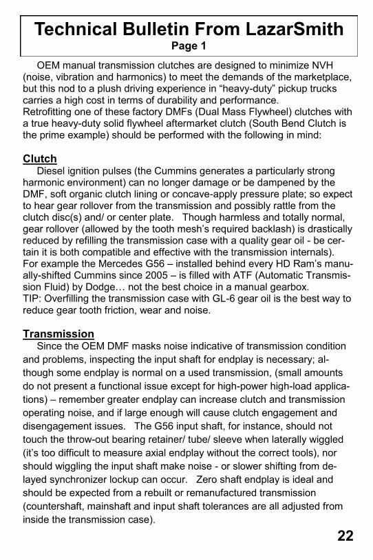
OEM manual transmission clutches are designed to minimize NVH (noise, vibration and harmonics) to meet the demands of the marketplace, but this nod to a plush driving experience in “heavy-duty” pickup trucks carries a high cost in terms of durability and performance. Retrofitting one of these factory DMFs (Dual Mass Flywheel) clutches with a true heavy-duty solid flywheel aftermarket clutch (South Bend Clutch is the prime example) should be performed with the following in mind:
Clutch Diesel ignition pulses (the Cummins generates a particularly strong harmonic environment) can no longer damage or be dampened by the DMF, soft organic clutch lining or concave-apply pressure plate; so expect to hear gear rollover from the transmission and possibly rattle from the clutch disc(s) and/ or center plate. Though harmless and totally normal, gear rollover (allowed by the tooth mesh’s required backlash) is drastically reduced by refilling the transmission case with a quality gear oil - be cer-tain it is both compatible and effective with the transmission internals). For example the Mercedes G56 – installed behind every HD Ram’s manu-ally-shifted Cummins since 2005 – is filled with ATF (Automatic Transmis-sion Fluid) by Dodge… not the best choice in a manual gearbox. TIP: Overfilling the transmission case with GL-6 gear oil is the best way to reduce gear tooth friction, wear and noise.
Transmission Since the OEM DMF masks noise indicative of transmission condition
and problems, inspecting the input shaft for endplay is necessary; al-
though some endplay is normal on a used transmission, (small amounts
do not present a functional issue except for high-power high-load applica-
tions) – remember greater endplay can increase clutch and transmission
operating noise, and if large enough will cause clutch engagement and
disengagement issues. The G56 input shaft, for instance, should not
touch the throw-out bearing retainer/ tube/ sleeve when laterally wiggled
(it’s too difficult to measure axial endplay without the correct tools), nor
should wiggling the input shaft make noise - or slower shifting from de-
layed synchronizer lockup can occur. Zero shaft endplay is ideal and
should be expected from a rebuilt or remanufactured transmission
(countershaft, mainshaft and input shaft tolerances are all adjusted from
inside the transmission case).
Technical Bulletin From LazarSmith
Page 1
22
Always check parts for damage and
to make sure you have all
components needed before
installation begins. There will be a
separate check list for parts
provided with this clutch. You must
check to ensure that you have all
parts needed. If any
damage occurs during installation
due to skipping your parts
checklist, South Bend Clutch will
not be liable for parts, labor or
damage that may occur.
*Torque specifications will be
provided with parts list
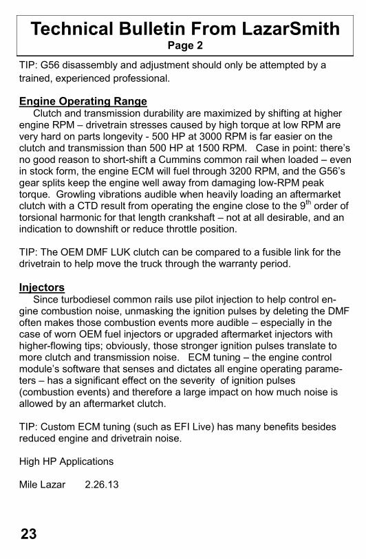
Technical Bulletin From LazarSmith
Page 2
TIP: G56 disassembly and adjustment should only be attempted by a
trained, experienced professional.
Engine Operating Range Clutch and transmission durability are maximized by shifting at higher engine RPM – drivetrain stresses caused by high torque at low RPM are very hard on parts longevity - 500 HP at 3000 RPM is far easier on the clutch and transmission than 500 HP at 1500 RPM. Case in point: there’s no good reason to short-shift a Cummins common rail when loaded – even in stock form, the engine ECM will fuel through 3200 RPM, and the G56’s gear splits keep the engine well away from damaging low-RPM peak torque. Growling vibrations audible when heavily loading an aftermarket clutch with a CTD result from operating the engine close to the 9th order of torsional harmonic for that length crankshaft – not at all desirable, and an indication to downshift or reduce throttle position. TIP: The OEM DMF LUK clutch can be compared to a fusible link for the drivetrain to help move the truck through the warranty period.
Injectors Since turbodiesel common rails use pilot injection to help control en-gine combustion noise, unmasking the ignition pulses by deleting the DMF often makes those combustion events more audible – especially in the case of worn OEM fuel injectors or upgraded aftermarket injectors with higher-flowing tips; obviously, those stronger ignition pulses translate to more clutch and transmission noise. ECM tuning – the engine control module’s software that senses and dictates all engine operating parame-ters – has a significant effect on the severity of ignition pulses (combustion events) and therefore a large impact on how much noise is allowed by an aftermarket clutch. TIP: Custom ECM tuning (such as EFI Live) has many benefits besides reduced engine and drivetrain noise. High HP Applications Mile Lazar 2.26.13
23
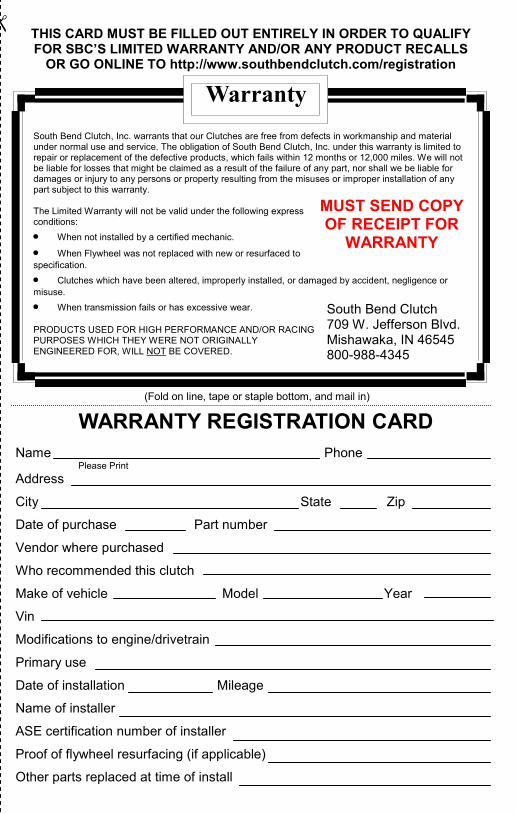
Warranty
WARRANTY REGISTRATION CARD
THIS CARD MUST BE FILLED OUT ENTIRELY IN ORDER TO QUALIFY FOR SBC’S LIMITED WARRANTY AND/OR ANY PRODUCT RECALLS
OR GO ONLINE TO http://www.southbendclutch.com/registration
(Fold on line, tape or staple bottom, and mail in)
Name Phone Please Print Address
City State Zip
Date of purchase Part number
Vendor where purchased
Who recommended this clutch
Make of vehicle Model Year
Vin
Modifications to engine/drivetrain
Primary use
Date of installation Mileage
Name of installer
ASE certification number of installer
Proof of flywheel resurfacing (if applicable)
Other parts replaced at time of install
South Bend Clutch, Inc. warrants that our Clutches are free from defects in workmanship and material under normal use and service. The obligation of South Bend Clutch, Inc. under this warranty is limited to repair or replacement of the defective products, which fails within 12 months or 12,000 miles. We will not be liable for losses that might be claimed as a result of the failure of any part, nor shall we be liable for damages or injury to any persons or property resulting from the misuses or improper installation of any part subject to this warranty. The Limited Warranty will not be valid under the following express conditions:
When not installed by a certified mechanic.
When Flywheel was not replaced with new or resurfaced to
specification.
Clutches which have been altered, improperly installed, or damaged by accident, negligence or
misuse.
When transmission fails or has excessive wear.
PRODUCTS USED FOR HIGH PERFORMANCE AND/OR RACING PURPOSES WHICH THEY WERE NOT ORIGINALLY ENGINEERED FOR, WILL NOT BE COVERED.
South Bend Clutch 709 W. Jefferson Blvd. Mishawaka, IN 46545 800-988-4345
MUST SEND COPY OF RECEIPT FOR
WARRANTY

South Bend Clutch 709 W. Jefferson Blvd. Mishawaka, IN 46545
Place
Postage
Here
“We Motivate The Shiftless”
Diesel Truck Clutch Owners Manual and Mechanic’s Guide
MUST GIVE TO TRUCK OWNER