laboratory study on core fracturing simulations for
TRANSCRIPT

Research ArticleLaboratory Study on Core Fracturing Simulations forWellbore Strengthening
Biao Ma,1,2 Xiaolin Pu ,1,2 Zhengguo Zhao,1,3 Hao Wang,1,2 and Wenxin Dong1,2
1State Key Laboratory of Oil and Gas Reservoir Geology and Exploitation, Southwest Petroleum University, Chengdu 610500, China2Laboratory of Drilling Fluid and Reservoir Protection, National Engineering Laboratory of Oil and Gas Drilling Technology,Chengdu 610500, China3Research Institute of Drilling Engineering Technology, Zhongyuan Petroleum Engineering Corporation, SINOPEC,Puyang 457001, China
Correspondence should be addressed to Xiaolin Pu; [email protected]
Received 14 May 2018; Revised 29 November 2018; Accepted 19 December 2018; Published 14 March 2019
Academic Editor: Marco Petitta
Copyright © 2019 Biao Ma et al. This is an open access article distributed under the Creative Commons Attribution License, whichpermits unrestricted use, distribution, and reproduction in any medium, provided the original work is properly cited.
The lost circulation in a formation is one of the most complicated problems that have existed in drilling engineering for a long time.The key to solving the loss of drilling fluid circulation is to improve the pressure-bearing capacity of the formation. The tendency isto improve the formation pressure-bearing capacity with drilling fluid technology for strengthening the wellbore, either to the lowfracture pressure of the formation or to that of the naturally fractured formation. Therefore, a laboratory study focused on corefracturing simulations for the strengthening of wellbores was conducted with self-developed fracture experiment equipment.Experiments were performed to determine the effect of the gradation of plugging materials, kinds of plugging materials, anddrilling fluid systems. The results showed that fracture pressure in the presence of drilling fluid was significantly higher thanthat in the presence of water. The kinds and gradation of drilling fluids had obvious effects on the core fracturing process. Inaddition, different drilling fluid systems had different effects on the core fracture process. In the same case, the core fracturepressure in the presence of oil-based drilling fluid was less than that in the presence of water-based drilling fluid.
1. Introduction
Fractured lost circulation is one of the types of drillingfluid-related lost circulation in drilling engineering. It is atechnological problem that always complicates drillingengineering. Usually, it is very difficult to eliminate fracturedlost circulation. It is also easy to induce a series of safetyproblems that cause collapse, blowouts, and disastrous acci-dents, leading to heavy losses of lives and property. Fracturedlost circulation is also a choke point in the development ofhigh-efficiency drilling technology. It is an urgent problemthat must be solved quickly [1–4].
As research on lost circulation has progressed, the solu-tions have gradually developed from simple plugging to acombination of plugging and prevention. Prevention hasbeen accepted widely, and a series of prevention technologies
such as improving the narrow window of safe mud density indrilling fluid technology, borehole strengthening technology,and wellbore strengthening technology have been developed.All these technologies are designed to improve the integrityof the wellbore and improve the formation fracture pressurein order to stop and prevent lost circulation [5].
Strengthening the wellbore essentially improves the frac-ture pressure of the formation in the wellbore. The methodfor strengthening the wellbore includes adding materialsthat can repair and protect the wellbore against drillingfluid. The wellbore fluid pressure is balanced by pluggingand supporting the formation fracture, which is known asactively taking measures to cope with the formation’s lostcirculation problem. Strengthening the wellbore includesconsidering the drilling fluid and the different kinds ofmaterials that are added to drilling fluid, and the object of
HindawiGeofluidsVolume 2019, Article ID 7942064, 18 pageshttps://doi.org/10.1155/2019/7942064
interest is the formation, namely, the wellbore. This ismainly intended to improve the performance of the drillingfluid to form a high-quality mud cake, which can strengthenthe wellbore.
Abundant research and applications for improving thewellbore drilling fluid technology to improve formationpressure-bearing capacity have been performed domesticallyand abroad. Nayberg classified plugging materials into threegroups according to their morphologies: fibres, flakes, andgranules. Moreover, the experimental results showed thatthe granular material can withstand higher pressure afterplugging the fractures, and the pressure-bearing effect wasbetter than that of the fibrous material and flaked material[6]. Alsaba and Nygaard discussed the most recent develop-ments in lost circulation materials (LCM) such as pluggingassurance technology and nanotechnology and also pre-sented a comprehensive summary of currently available lostcirculation materials. In addition, they reclassified lost circu-lation materials into seven categories based on their appear-ance and application: granular, flaky, fibrous, LCM mixture,acid/water-soluble, high fluid loss squeeze, swellable/hydra-table combinations, and nanoparticles. The authors proposedthat due to different understandings of the mechanism ofwellbore strengthening, it was difficult to develop a unifiedstandard for testing methods [7]. Experiments with slotteddisks that simulated fractures have been performed, whereinthe amount of fluid loss and sealing pressure was used asevaluation criteria. Jeennakorn et al. investigated LCMbehaviour with different slot designs and fluid flow patternsfor water-based and oil-based drilling fluids. They improvedthe experiment by adding a bladder-type accumulator to thesystem to provide instantaneous flow conditions. The resultsof the experimental setup showed that the set of experimentscan change the result. As such, caution should be taken whenquantitatively comparing LCM tests based on slot disks todifferent experimental setups [8]. Alsaba et al. believed therewere shortcomings in the laboratory experimental setups thatutilized slotted disks. A fluid loss apparatus was developedto mimic wellbore circulation to study the effect of annularfluid flow on building an LCM bridge at the fracture aper-ture [9]. Tehrani et al. found that strengthening the well-bore was achieved by plugging and propping fractures.The effect of strengthening the wellbore is closely relatedto the kind of materials used for plugging, the gradationand the filter loss of drilling fluid. It was found that gra-phitic materials may be more effective in propping fracturesopen, whereas carbonates and cellulosic materials canimprove the effect of plugging [10]. Wang et al. studiedthe effect of plugging materials on plugging and supportingfractures using the boundary element method. The relation-ships between fracture pressure, wellbore pressure, wellboreradius, fracture length, and other parameters under theaction of plugging and supporting of materials were ana-lysed [11, 12]. Friedheim et al. developed a high-fluid-lossand high-strength (HFHS) plugging material. The HFHSwas designed to be applicable over a wide range of losses,miscible with aqueous and nonaqueous fluid, pumpablethrough measurement while drilling (MWD) tools and bot-tomhole assembly (BHA), and resistant to high shear stress,
even after being weighted with barite. The material is mainlycomposed of cellulosic fibres and particles. The strength ofmud cakes formed after filtration is very high. In addition,the material has been applied well in wells along the northslope of Alaska, the Grimes of Texas, and offshore Indonesia[13]. Contreras and Nwaoji introduced a method forstrengthening the wellbore by adding a mixture of nanoma-terials and graphite to the oil-based drilling fluid, whichshowed good results with respect to wellbore strengtheningand improved formation pressure-bearing capacity. Thepressure test was carried out in a 9/16″ wellbore. Two kindsof drilling fluid systems are prepared using calcium-basednanoparticles and iron-based nanoparticles, respectively.The fracture pressure was increased by 65% whencalcium-based nanoparticles were used, whereas fracturepressure increased by 39% in the presence of iron-basednanoparticles. The optimum nanoparticle concentrationswere established after a comprehensive experimental screen-ing. A strong relationship between wellbore strengtheningand mud filtration at high pressure and high temperature,using a filter press on ceramic discs, was determined [14,15]. Whitfill et al. evaluated resilient graphitic carbon usingexperiments and pointed out that resilient graphitic carbonhas many special properties that can be applied to the opera-tion of plugging. The addition of resilient graphitic carboncan improve the resilience of the plugging materials [16–18]. Savari et al. suggested that the resilient materials playedan important role in wellbore strengthening and validatedthe characteristics of resilient graphitic carbon related toresiliency, lubricity, resistance to attrition, and compatibilitywith downhole tools. It had a good effect in wellborestrengthening applications. Whether in sandstone or carbon-ate formations, with water-based drilling fluid or oil-baseddrilling fluid, resilient materials have shown obviousstrengthening effects on wellbores [19]. Mansour et al. intro-duced a new class of “smart lost circulation materials” toeffectively seal fractures. The smart LCMs were made out ofthermoset shape memory polymers that were activated uponexposure to the formation’s in situ temperature, whichcaused expansion and acted as an effective seal for the frac-tures. The physical properties of the smart lost circulationmaterials could prevent damage to production zones and toolplugging [20]. Collins et al. noted the problem associatedwith the amount of plugging materials when the drilling fluidwas mixed and pointed out that it is necessary to consider thedensity of the plugging materials and that the amount ofplugging materials should be calculated according to the vol-ume, rather than the weight. When adding materials accord-ing to the weight percentage, under the condition that theweights are equal, the volume of materials with lower densityis larger. When it is added, the plugging results will beaffected [21]. Pu Xiaolin studied the drilling fluid technologyassociated with improving the formation pressure-bearingcapacity with the theory of temporary shielded plugging.The formula system was developed by adjusting the grada-tion of calcium carbonate materials in the drilling fluid andusing inert water loss material as filling materials and hashad achieved remarkable effects in the lost-circulation zoneof the Luohe Formation in the Changqing Oilfield, effectively
2 Geofluids
improving formation pressure-bearing capacity and ensuringa smooth drilling process and wellbore quality [22].
Wellbore-strengthening drilling fluid technology hasbeen used widely both domestically and abroad. Respectivepreventative and plugging drilling fluid systems haveachieved perfect results [23–37], which is very important tostudies dedicated to improving formation pressure-bearingcapacity. Many field experiments have also confirmed that areasonable material ratio and drilling fluid system canimprove the formation pressure-bearing capacity. For a brit-tle formation with low pressure-bearing capacity, when thedrilling fluid column pressure is more than the formationfracture pressure, the formation will be fractured, and thenlost circulation will occur. The low pressure-bearing capacityof a brittle formation is a significant cause of drilling fluid lostcirculation. As such, it is important to improve the fracturepressure of brittle formation.
The existence of a mud cake can affect the formation frac-turing process. In addition, the different mud cake perfor-mances have different effects on the formation fracturingprocess. The yield strength, thickness, and permeability ofthe mud cake can affect formation fracture pressure. The per-formance of the mud cake depends on the composition of thedrilling fluid. To increase the formation pressure-bearingcapacity, different kinds of plugging materials are usuallyadded to the drilling fluid. How the addition of these mate-rials affects the drilling fluid-related strengthening of thewellbore must be to explored and verified in practice. There-fore, many experiments focused on core fracturing simula-tions for strengthening the wellbore must be carried out tostudy the effect of drilling fluids and different kinds of plug-ging materials on strengthening the wellbore.
2. Materials and Methods
2.1. Setup. The self-developed equipment for the fracturingexperiment consisted of three parts: (1) fluid intrusion sys-tem, (2) core holding system, and (3) pressure control andmeasurement system.
The fluid intrusion system consists of an outer sleevepedestal (11), an outer sleeve (12), a piston (13), an outersleeve head cover (14), an outer sleeve bottom cover (15),and a pressure sensor (16). The outer sleeve bottom cover isfixed on the outer sleeve pedestal. The lower end of the outersleeve is fixed inside the outer sleeve bottom cover. The outersleeve head cover is arranged on the top of the outer sleeve,and the piston is fitted inside the outer sleeve. The pressuresensor is set up at the top of the outer sleeve head cover.
The core holding system consists of a base support (21), abracket (22), an autoclave (23), a rubber sleeve (24), an inletline (25), a plug (26), an inlet plunger (27), an outlet plunger(28), an inlet hole (29), and a silicon seal (210). The autoclaveis a hollow cylindrical structure. The inlet plunger is fixed atthe top of the autoclave, and the outlet plunger is fixed at thebottom of the autoclave. The rubber sleeve is installed insidethe autoclave. An airtight cavity is formed between the innerwall of the autoclave and the outer wall of the rubber sleeve toexert confining pressure on the core. The cavity that isformed by the inner wall of the rubber sleeve, the inlet
plunger, and the outlet plunger is internally fixed with thecore. The two sections of the central circular hole of the coreare inserted with the inlet line and the plug, respectively, anda closed space is formed. The inlet line passes through theinlet plunger, and the plug passes through the outlet plunger.The core is fixed in the autoclave. The inlet line and the plugare also tightly fixed in the core. The other end of the inletline is connected to the outlet of the outer barrel cover. Theouter wall of the autoclave also has an inlet hole. The bracketis vertically fixed on the base support and is connected to theautoclave. The silicon seals are, respectively, fixed betweenthe inlet line and the inner hole of the core and between theplug and the inner hole of the core. Figure 1 is a schematicdiagram of the fracturing experiment equipment.
The pressure control and measurement system consistsof a confining pressure pump (31), a displacement pump(32), a confining pressure sensor (33), a displacement pres-sure sensor (34), a core pressure sensor (35), and a computer(36). The confining pressure sensor is installed on the confin-ing pressure pump. The confining pressure pump is con-nected with the inlet hole. The displacement pressuresensor is installed on the displacement pressure pump. Thedisplacement pump is internally connected with the outersleeve bottom cover. The computer is connected to the pres-sure sensors.
The theory behind the fracturing experiment equip-ment is that pressure offered by the pumps goes throughthe fluid intrusion system and drives drilling fluid intothe core’s inner hole in the core holding system, whichcan fracture the core. Therefore, the effect of improvingformation pressure-bearing capacity, or wellbore strength-ening facilitated by drilling fluid, will be evaluated.
In the test, first, the prepared drilling fluid is poured intothe sleeve in the fluid intrusion system. The outer sleeve headcover is tightened. The pressure sensors are connected to thecomputer, and the outer sleeve bottom cover is connected tothe pressure control and measurement systems. The intactcore is taken, and the inlet pipe and plug are inserted intothe central circular hole of the core. The core is then placedin the autoclave of the core holding system and is positionedin the middle of the rubber sleeve. The inlet plunger and out-let plunger are tightened to fix the core. The inlet pipe is con-nected to the outlet at the upper end of the outer sleeve headcover, and the inlet hole is connected with the pressure con-trol and measurement systems. The pressure control andmetering systems are initiated, and the required confiningpressure is set by the computer. The confining pressurepump is initiated, and hydraulic oil is injected into the spacebetween the autoclave and the rubber sleeve to apply the con-fining pressure on the core. After the confining pressurereaches the required value, the displacement pressure is setand the displacement pump is initiated. The hydraulic oilpushes the piston upward to drive the drilling fluid into thecentral circular hole of the core. With the increase inpressure, the core is finally fractured. During this period,the confining pressure sensor, displacement pressure sensor,and core pressure sensor, respectively, record the confiningpressure, displacement pressure, and pressure change of theinner hole of the core, and the recorded values are used for
3Geofluids

subsequent tests. After the core is fractured, the drilling fluidor filtrate flows out through the guide groove on the end-faceof the outlet plunger and the plug.
2.2. Materials
2.2.1. Core. The core used in the experiment was cylindrical,and its length was 140-150mm with a diameter of 100mm.There was a circular hole with a diameter of 10mm in thecentre of the core. Figure 2 shows a schematic diagram andphotograph of the core. The core was made of cement mor-tar. The cement was ordinary 425 Portland cement. The sandwas composed of quartz. The particle size range of the sandwas 0.2-2mm.
The physical properties and mechanical properties of thecore are shown in Tables 1 and 2.
2.2.2. Plugging Materials
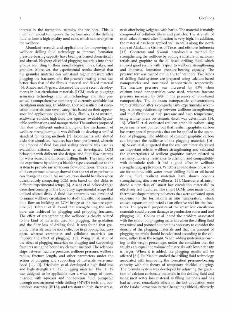
(1) Particulate Materials. The selected particulate materialsincluded nanomaterials, calcium carbonate particles, quartzparticles, graphite particles, and new, self-developed, high-strength polyester particles. Figure 3 shows several kinds ofparticulate materials used in the experiments.
Because different kinds of particles would be needed inthe experiment, for the sake of completeness, all of the parti-cles were numbered and their characteristics are shown inTable 3.
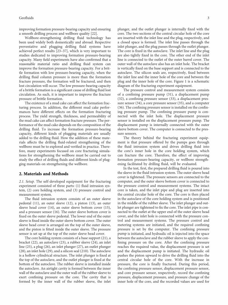
(2) Fibrous Material. The fibrous material selected for theexperiment was paper fibre. The paper fibre was dark grey,light-weight, and less than 3mm in diameter. Its physicaland chemical properties were stable. The paper fibre is shownin Figure 4. Paper fibre was helpful in reuniting particulatematerials, filling particulate materials in micropores, andimproving the integrity and compactness of plugged zone.
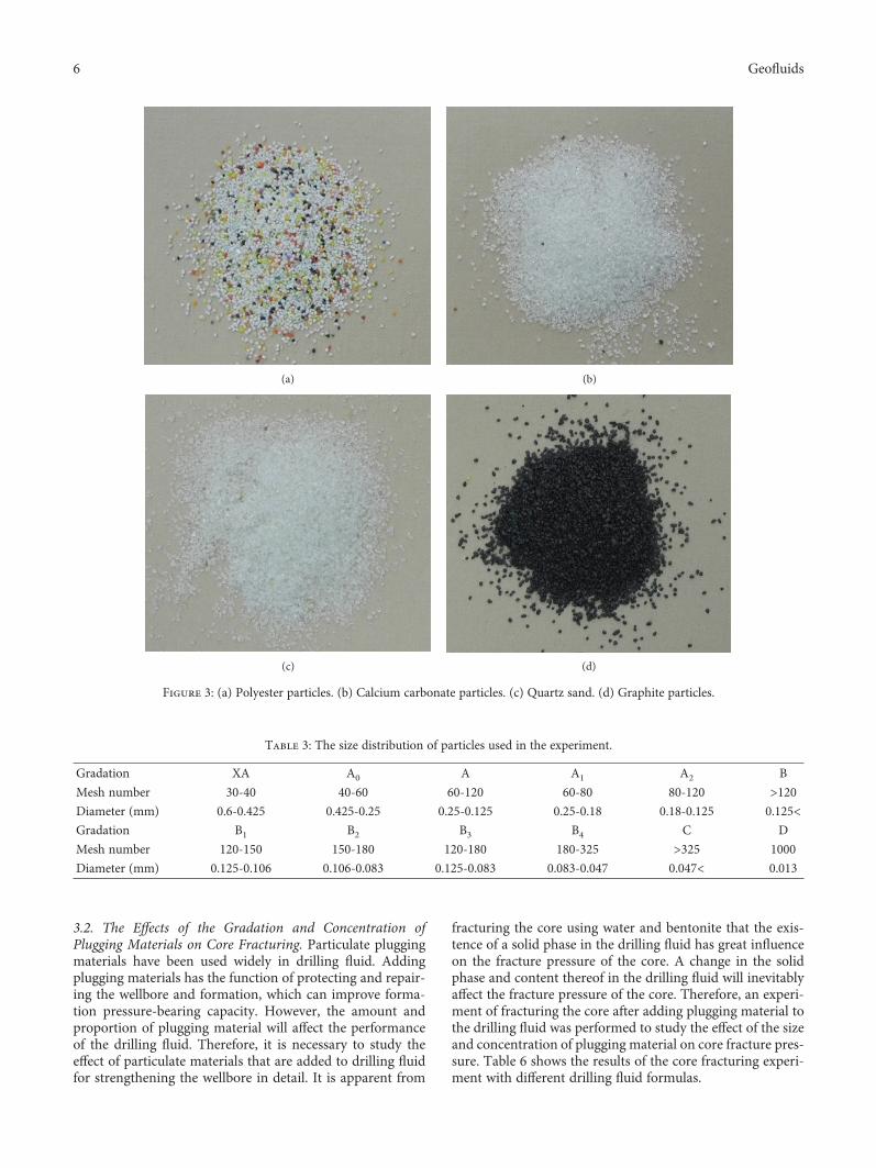
(3) Flaky Material. The flaky material selected for the exper-iment was a new kind of high-friction material with high
strength, uneven surfaces, and fibrous edges. The flaky mate-rial had a package effect on particulate materials. At the sametime, the frictional resistance between the plugging layer andthe fracture wall was enhanced, which was beneficial to theformation and stabilization of the plugging layer. Figure 5shows the selected flaky material.
(4) Other Materials. Emulsified asphalt was used in the exper-iment. The asphalt materials are deformable, and they willdeform to fill various pores and fractures under the influenceof temperature and pressure, which can improve the plug-ging performance of drilling fluid and can form more com-pact mud cakes.
2.2.3. Base Fluid. Water-based and oil-based drilling fluidswere used in the experiment. The formulas and propertiesof the drilling fluids are shown in Table 4.
The water-based drilling fluid was an ordinary disper-sion system. The oil-based base drilling fluid was anoil-water emulsion drilling fluid system, and the oil-waterratio was 8 : 2.
The flow curves for the water- and oil-based drillingfluids are shown in Figure 6.
2.3. Method. The experiment for the core fracturing simu-lation for strengthening the wellbore was conducted undera confining pressure of 2MPa. The core was used as thesimulated formation. The drilling fluid for fracturing thecore was injected into the inner hole in the core at a speedof 2mL/min.
3. Results and Discussion
3.1. The Difference betweenWater and Bentonite Mud in CoreFracturing. There are many existing studies on hydraulicfracturing. In addition to hydraulic fracturing in oil and gasfield simulations, there has been more attention paid to waterconservancy, mines, and other fields. Hydraulic fracturing is
27
29
4
23
221 28
26
1
15
12
13
1614
33
32
11
3
34
35
31
3622
24
210
25
Figure 1: Schematic diagram of the fracturing experiment equipment.
4 Geofluids

different from drilling fluid fracturing. Therefore, a bentoniteslurry and water were used in the experiment. The fracturingresults are compared in Table 5. It is apparent that under thesame experimental conditions, the fracture pressure of thecore under water pressure was much lower than under theaction of the bentonite slurry.
Figure 7 shows curves of the change in pressure over timein the inner hole during the core fracturing process for waterand the bentonite slurry. When the water was injected intothe core with small displacement, water permeated throughthe core and it was difficult for pressure to accumulate insidethe core. Therefore, it was necessary to inject water with largedisplacement into the core. Under the influence of largedisplacement, the pressure inside the core increased rapidly
and then fractured the core. When the bentonite slurry wasinjected into the core with small displacement, because ofthe characteristics of the drilling fluid and because the mudcake formed in the walls of the pores in core, it was easy toaccumulate pressure inside the core and fracture the core.Figure 8 shows the fractured core. There is no obvious changein the surface of core before and after fracturing. There are nofracture traces or visible fractures on the core surface. How-ever, there are visible fractures on the surface of core thatwas fractured by the bentonite slurry. Essentially symmetricfractures appear on the fractured core. Visible fractures canbe observed on the sides and ends of the core.
There is a difference in the forms of fractures producedby water and the bentonite slurry. When the water was usedfor fracturing the core, the pore pressure near the walls ofpores increases rapidly and reaches the water pressure inthe inner hole of the core. Because the displacement flow isbeyond the absorption capacity of the core and the pressurein the inner hole of the core is also increasing, under the jointinfluence of pore pressure and inner hole pressure, the core isfractured. The pore pressure contributes greatly to the frac-turing of the core. When the bentonite slurry was used forfracturing the core, bentonite was deposited on the wall ofthe inner hole to form mud cakes. Due to the low permeabil-ity of the mud cakes, there was very little liquid phase in thecore, which did not cause a rapid increase in pore pressurewithin the core. In addition, the mud cakes had an effect ofprotecting the wellbore, buffering the pressure. When waterwas used for fracturing the core, the permeation of waterhad great influence. The fracturing of the core was essentiallypermeability damage. However, under the influence of thedrilling fluid, the permeation of filtrate had relatively littleeffect on the fracturing of the core. The fracture mechanismsof the core under the action of water and drilling fluid are dif-ferent, which also provides evidence that drilling fluid canincrease the fracture pressure in the core.
140-150 mm
10 mm
100 mm
Figure 2: Schematic diagram and photograph of the core.
Table 1: Porosity and permeability of the core.
CoreCement sandwater = 1 3 0 9
Cement sandwater = 1 2 0 67
Porosity (%)
21.77
Average: 22.58
21.52
Average: 20.1923.61 18.76
22.35 20.29
Permeability (mD)
2.541
Average: 2.48
0.124
Average: 0.1282.227 0.146
2.673 0.115
Table 2: Mechanical parameters of the core.
CoreCement sandwater = 1 3 0 9
Cement sandwater = 1 2 0 67
Young’s modulus (GPa) 6.99 23.87
Poisson’s ratio 0.2 0.23
Compressive strength 35 49
Tensile strength 5.42 9.34
5Geofluids
3.2. The Effects of the Gradation and Concentration ofPlugging Materials on Core Fracturing. Particulate pluggingmaterials have been used widely in drilling fluid. Addingplugging materials has the function of protecting and repair-ing the wellbore and formation, which can improve forma-tion pressure-bearing capacity. However, the amount andproportion of plugging material will affect the performanceof the drilling fluid. Therefore, it is necessary to study theeffect of particulate materials that are added to drilling fluidfor strengthening the wellbore in detail. It is apparent from
fracturing the core using water and bentonite that the exis-tence of a solid phase in the drilling fluid has great influenceon the fracture pressure of the core. A change in the solidphase and content thereof in the drilling fluid will inevitablyaffect the fracture pressure of the core. Therefore, an experi-ment of fracturing the core after adding plugging material tothe drilling fluid was performed to study the effect of the sizeand concentration of plugging material on core fracture pres-sure. Table 6 shows the results of the core fracturing experi-ment with different drilling fluid formulas.
(a) (b)
(c) (d)
Figure 3: (a) Polyester particles. (b) Calcium carbonate particles. (c) Quartz sand. (d) Graphite particles.
Table 3: The size distribution of particles used in the experiment.
Gradation XA A0 A A1 A2 B
Mesh number 30-40 40-60 60-120 60-80 80-120 >120Diameter (mm) 0.6-0.425 0.425-0.25 0.25-0.125 0.25-0.18 0.18-0.125 0.125<Gradation B1 B2 B3 B4 C D
Mesh number 120-150 150-180 120-180 180-325 >325 1000
Diameter (mm) 0.125-0.106 0.106-0.083 0.125-0.083 0.083-0.047 0.047< 0.013
6 Geofluids
3.2.1. Gradation
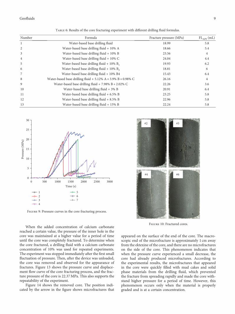
(1) The Influence of Material Gradation on Fracture Pressure.Particulate materials of different sizes that are added to thedrilling fluid would affect the performance of the drillingfluid and, thus, the core fracturing process. An experimentof core fracturing was performed using drilling fluid with dif-ferent sizes of calcium carbonate particles. Figure 9 shows thepressure curves derived from the experiment. Curve #1 is thecurve for fracturing based on the use of water-based drillingfluid, used here as a comparison curve.
As shown in the figure, different sizes of particles havedifferent effects on the fracturing process. In experiment #2,the material size was larger and the results were almost iden-tical to those of the base drilling fluid, indicating that the par-ticle size had less influence on the performance of the drillingfluid. The fracture pressures of the core in experiments #3and #4 were significantly improved compared to that of thebase drilling fluid. Moreover, after the core was fractured inexperiment #3, the pressure remained at a higher value,which was different from the results of other experiments.In addition, in the other experiments, the fracture pressureof the core was not significantly improved compared to thatunder the action of the base drilling fluid and ratherdecreased somewhat. In experiments #5, #6, and #7, theparticulate materials greatly increased the water loss of the
drilling fluid, and the material affected the performance ofthe mud cakes. It is also apparent that the slopes of thepressure curves of these three experiments are significantlysmaller than those of the other experiments.
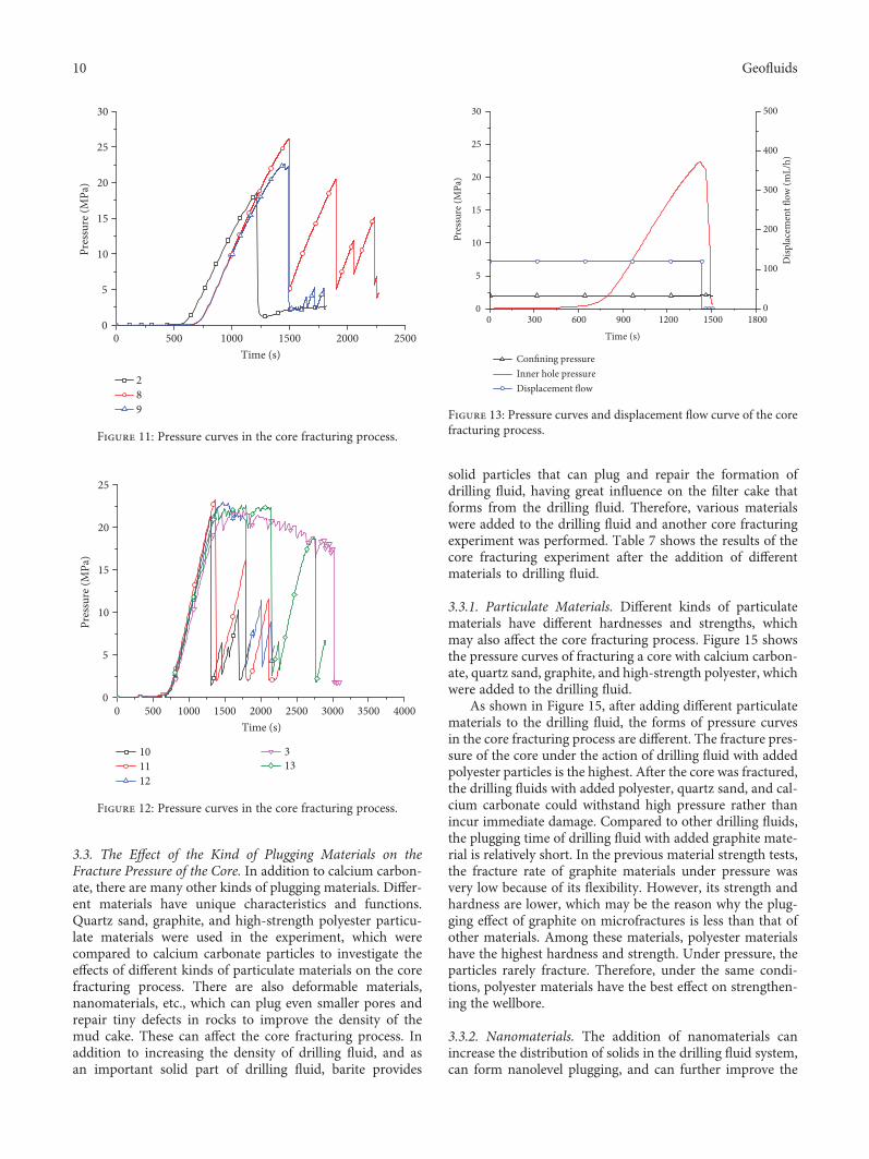
Figure 10 shows the cores fractured in several experi-ments, in which longitudinal fractures formed after the frac-tures on the sides of the cores.
According to the experimental results, particle size has agreat influence on the core fracturing process. It is difficult toincrease the fracture pressure of the core under the action ofthe particles with a size greater than 50mm and a relativelysingle size (such as in experiments #2, #5, #6, and #7). More-over, the smaller the particle size of a single size particle, thissize range is not conducive to increasing the fracture pressureof the core. For example, experiment #7 was repeated manytimes and yielded consistent results, and the fracture pressureof the core was significantly lower than that of the base dril-ling fluid. When the particle size is less than 50mm, the per-formance of the drilling fluid improves, and the fracturepressure of the core improves greatly. In addition, the particlesize distribution range is wide; that is, the particles of varioussizes occur, which can significantly increase the fracture pres-sure of the core due to the interactions between particles.
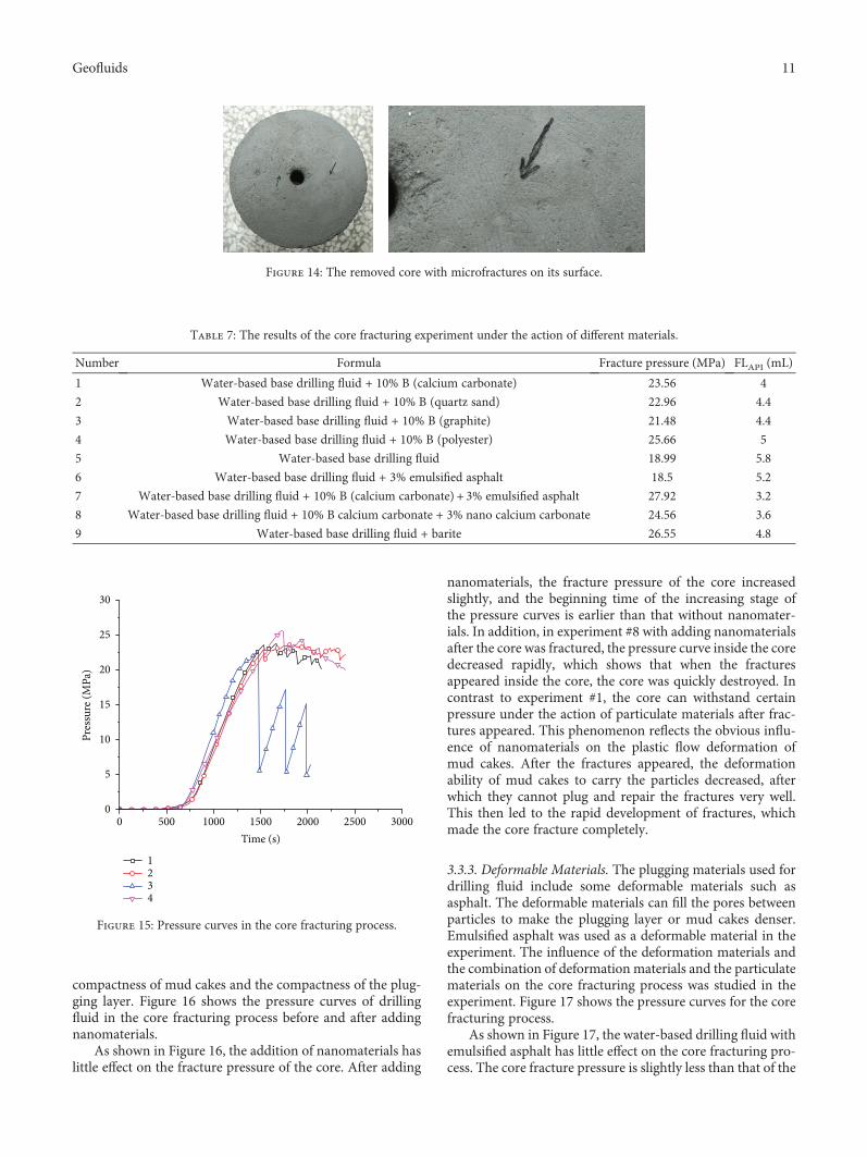
(2) The Effect of the Gradation of Plugging Materials on theCore Fracturing Process. The gradation of particles representsthe proportion of particles with different sizes. By optimizingthe gradation of particulate materials, the density of pluggingcan be improved. However, for the experiment of fracturingintact core, the gradation of particles can affect the abilityof the drilling fluid and can protect the core. Therefore, theinfluence of particle gradation on the core fracturing processwas investigated.
Figure 11 shows the pressure curves in the core fracturingprocess for three particle gradations. Based on the pressurecurves, the gradation of the materials also has a great influ-ence on the core fracturing process. The size of the particlesin experiment #2 is large and the size distribution is relativelynarrow. The influence on the mud cake is very small, and thefracture pressure of the core is low. The particle gradation inexperiment #8 is relatively good, and the fracture pressure ofthe core is 26.16MPa. The water loss of drilling fluid is small,and the filter cake is relatively dense. As shown by the figure,the drilling fluid was continuously pumped into the core afterthe core was fractured. Under this action, the core fracturepressure can be reconstructed, and the pressure of the corerupture was more than 20MPa. The overall particle size inexperiment #9 is less than that in experiment #8, and its effectis also slightly worse than in experiment #8. However, the sizeof particles in formula #9 is relatively small and the size dis-tribution is relatively wide. Formula #9 has a great influenceon the mud cake and the walls of pores in the core. The corefracture pressure under its action is higher than in experi-ment #2. In conclusion, in order to increase the fracture pres-sure of the formation, the selection of particle size gradationshould consider the following: particle size cannot be too uni-tary, and the size distribution should be wide. Coarse parti-cles, fine particles, and microfine particles have differentfunctions, and the effect of their combination will be better.
Figure 4: Paper fibre.
Figure 5: High-friction flaky material.
7Geofluids

3.2.2. Concentration. It was found in experiment #3 that thefracture pressure of the core was higher, and the fracturedcore can withstand higher pressure without immediatedamage, which was a good effect of protecting the walls ofthe pores and strengthening the wellbore. Therefore, basedon the formula of experiment #3, the concentration ofparticulate material was changed to observe the influenceof particle concentration on the core fracturing process.Figure 12 shows pressure curves of the core fracturingprocess under the action of drilling fluid with differentconcentrations of particulate materials. For consistency,the pressure curves of experiment #3 are those of the exper-iments described above.
With an increase in calcium carbonate concentration, thefiltration loss of drilling fluid is not significant, which has lit-tle effect on the density of the mud cake that is formed by thedrilling fluid. The figure shows that under different particleconcentration conditions, the fracture pressures of the coreare slightly different, indicating that after the size distributionof the material is determined, the change in concentrationhas relatively little effect on the fracture pressure of the core.However, a change in the concentration of particulate mate-rial has different effects on the performance of core fractur-ing. When the concentration of added calcium carbonatereached and exceeded 8.5% after the core was fractured, thepressure of the inner hole in the core could be maintainedat a higher value for a period of time, which extended thetime of the core from fracture to total destruction. Thisphenomenon is very beneficial for improving formationpressure-bearing capacity.
Table 4: Formulas and properties of drilling fluids.
Number Formula ρ(g/cm3)
1 Water-based drilling fluid: 4% bentonite slurry + 2% SMP-2 + 0.3% CMC-HV 1.04
2Oil-based drilling fluid: white oil + water (25% of oil weight) + 2% primary emulsifierMOEMUL+ 2% coemulsifier MOCOAT + 2% CaO + 1% filtrate reducer JFL-1 +CaCl2
(25% of water weight) + 0.5% shear-strength improving agent TQ-10.902
0 200 400 600 800 1000 12000
10
20
30
40
50
60
Shea
r stre
ss (P
a)
Shear rate (1/s)
Water-based drilling fluidOil-based drilling fluid
Figure 6: The flow curves for the drilling fluids.
Table 5: The results of water and bentonite slurry fracturingexperiments.
Number Formula Fracture pressure (MPa) FLAPI (mL)
1 Water 5.73 — —
24% bentonite
slurry21.97 28.4
0 1000 2000 3000 4000 50000
5
10
15
20
25
Pres
sure
(MPa
)
Time (s)
12
Figure 7: Pressure curves of fracturing core by water and abentonite slurry.
#1
Fractures
#2
Figure 8: The cores fractured by water (#1) and a bentoniteslurry (#2).
8 Geofluids
When the added concentration of calcium carbonatereached a certain value, the pressure of the inner hole in thecore was maintained at a higher value for a period of timeuntil the core was completely fractured. To determine whenthe core fractured, a drilling fluid with a calcium carbonateconcentration of 10% was used for repeated experiments.The experiment was stopped immediately after the first smallfluctuation of pressure. Then, after the device was unloaded,the core was removed and observed for the appearance offractures. Figure 13 shows the pressure curve and displace-ment flow curve of the core fracturing process, and the frac-ture pressure of the core is 22.37MPa. This also supports therepeatability of the experiment.
Figure 14 shows the removed core. The position indi-cated by the arrow in the figure shows microfractures that
appeared on the surface of the end of the core. The macro-scopic end of the microfracture is approximately 1 cm awayfrom the ektexine of the core, and there are no microfractureson the side of the core. This phenomenon indicates thatwhen the pressure curve experienced a small decrease, thecore had already produced microfractures. According tothe experimental results, the microfractures that appearedin the core were quickly filled with mud cakes and solidphase materials from the drilling fluid, which preventedthe fracture from spreading rapidly and made the core with-stand higher pressure for a period of time. However, thisphenomenon occurs only when the material is properlygraded and is at a certain concentration.
Table 6: Results of the core fracturing experiment with different drilling fluid formulas.
Number Formula Fracture pressure (MPa) FLAPI (mL)
1 Water-based base drilling fluid 18.99 5.8
2 Water-based base drilling fluid + 10% A 18.66 5.4
3 Water-based base drilling fluid + 10% B 23.56 4
4 Water-based base drilling fluid + 10% C 24.04 4.4
5 Water-based base drilling fluid + 10% B1 19.93 6.2
6 Water-based base drilling fluid + 10% B2 18.81 6
7 Water-based base drilling fluid + 10% B4 15.43 6.4
8 Water-based base drilling fluid + 5.12% A+ 3.9% B+ 0.98% C 26.16 4
9 Water-based base drilling fluid + 7.98% B+ 2.02% C 22.26 3.6
10 Water-based base drilling fluid + 3% B 20.91 6.4
11 Water-based base drilling fluid + 6.5% B 23.25 5.8
12 Water-based base drilling fluid + 8.5% B 22.96 5.8
13 Water-based base drilling fluid + 15% B 22.24 5.8
0 500 1000 1500 2000 2500 30000
5
10
15
20
25
30
Pres
sure
(MPa
)
Time (s)
1234
567
Figure 9: Pressure curves in the core fracturing process.
#2 #3
#4 #6
Figure 10: Fractured cores.
9Geofluids
3.3. The Effect of the Kind of Plugging Materials on theFracture Pressure of the Core. In addition to calcium carbon-ate, there are many other kinds of plugging materials. Differ-ent materials have unique characteristics and functions.Quartz sand, graphite, and high-strength polyester particu-late materials were used in the experiment, which werecompared to calcium carbonate particles to investigate theeffects of different kinds of particulate materials on the corefracturing process. There are also deformable materials,nanomaterials, etc., which can plug even smaller pores andrepair tiny defects in rocks to improve the density of themud cake. These can affect the core fracturing process. Inaddition to increasing the density of drilling fluid, and asan important solid part of drilling fluid, barite provides
solid particles that can plug and repair the formation ofdrilling fluid, having great influence on the filter cake thatforms from the drilling fluid. Therefore, various materialswere added to the drilling fluid and another core fracturingexperiment was performed. Table 7 shows the results of thecore fracturing experiment after the addition of differentmaterials to drilling fluid.
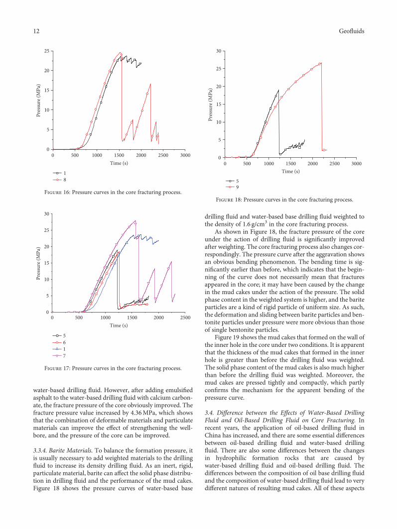
3.3.1. Particulate Materials. Different kinds of particulatematerials have different hardnesses and strengths, whichmay also affect the core fracturing process. Figure 15 showsthe pressure curves of fracturing a core with calcium carbon-ate, quartz sand, graphite, and high-strength polyester, whichwere added to the drilling fluid.
As shown in Figure 15, after adding different particulatematerials to the drilling fluid, the forms of pressure curvesin the core fracturing process are different. The fracture pres-sure of the core under the action of drilling fluid with addedpolyester particles is the highest. After the core was fractured,the drilling fluids with added polyester, quartz sand, and cal-cium carbonate could withstand high pressure rather thanincur immediate damage. Compared to other drilling fluids,the plugging time of drilling fluid with added graphite mate-rial is relatively short. In the previous material strength tests,the fracture rate of graphite materials under pressure wasvery low because of its flexibility. However, its strength andhardness are lower, which may be the reason why the plug-ging effect of graphite on microfractures is less than that ofother materials. Among these materials, polyester materialshave the highest hardness and strength. Under pressure, theparticles rarely fracture. Therefore, under the same condi-tions, polyester materials have the best effect on strengthen-ing the wellbore.
3.3.2. Nanomaterials. The addition of nanomaterials canincrease the distribution of solids in the drilling fluid system,can form nanolevel plugging, and can further improve the
0 500 1000 1500 2000 25000
5
10
15
20
25
30
Pres
sure
(MPa
)
Time (s)
289
Figure 11: Pressure curves in the core fracturing process.
0 500 1000 1500 2000 2500 3000 3500 40000
5
10
15
20
25
Pres
sure
(MPa
)
Time (s)
101112
313
Figure 12: Pressure curves in the core fracturing process.
0 300 600 900 1200 1500 18000
5
10
15
20
25
30
Confining pressureInner hole pressureDisplacement flow
Time (s)
Pres
sure
(MPa
)
0
100
200
300
400
500
Disp
lace
men
t flow
(mL/
h)
Figure 13: Pressure curves and displacement flow curve of the corefracturing process.
10 Geofluids
compactness of mud cakes and the compactness of the plug-ging layer. Figure 16 shows the pressure curves of drillingfluid in the core fracturing process before and after addingnanomaterials.
As shown in Figure 16, the addition of nanomaterials haslittle effect on the fracture pressure of the core. After adding
nanomaterials, the fracture pressure of the core increasedslightly, and the beginning time of the increasing stage ofthe pressure curves is earlier than that without nanomater-ials. In addition, in experiment #8 with adding nanomaterialsafter the core was fractured, the pressure curve inside the coredecreased rapidly, which shows that when the fracturesappeared inside the core, the core was quickly destroyed. Incontrast to experiment #1, the core can withstand certainpressure under the action of particulate materials after frac-tures appeared. This phenomenon reflects the obvious influ-ence of nanomaterials on the plastic flow deformation ofmud cakes. After the fractures appeared, the deformationability of mud cakes to carry the particles decreased, afterwhich they cannot plug and repair the fractures very well.This then led to the rapid development of fractures, whichmade the core fracture completely.
3.3.3. Deformable Materials. The plugging materials used fordrilling fluid include some deformable materials such asasphalt. The deformable materials can fill the pores betweenparticles to make the plugging layer or mud cakes denser.Emulsified asphalt was used as a deformable material in theexperiment. The influence of the deformation materials andthe combination of deformation materials and the particulatematerials on the core fracturing process was studied in theexperiment. Figure 17 shows the pressure curves for the corefracturing process.
As shown in Figure 17, the water-based drilling fluid withemulsified asphalt has little effect on the core fracturing pro-cess. The core fracture pressure is slightly less than that of the
Figure 14: The removed core with microfractures on its surface.
Table 7: The results of the core fracturing experiment under the action of different materials.
Number Formula Fracture pressure (MPa) FLAPI (mL)
1 Water-based base drilling fluid + 10% B (calcium carbonate) 23.56 4
2 Water-based base drilling fluid + 10% B (quartz sand) 22.96 4.4
3 Water-based base drilling fluid + 10% B (graphite) 21.48 4.4
4 Water-based base drilling fluid + 10% B (polyester) 25.66 5
5 Water-based base drilling fluid 18.99 5.8
6 Water-based base drilling fluid + 3% emulsified asphalt 18.5 5.2
7 Water-based base drilling fluid + 10% B (calcium carbonate) + 3% emulsified asphalt 27.92 3.2
8 Water-based base drilling fluid + 10% B calcium carbonate + 3% nano calcium carbonate 24.56 3.6
9 Water-based base drilling fluid + barite 26.55 4.8
30
25
20
15
Pres
sure
(MPa
)
10
5
00 500 1000 1500
Time (s)
1234
2000 2500 3000
Figure 15: Pressure curves in the core fracturing process.
11Geofluids
water-based drilling fluid. However, after adding emulsifiedasphalt to the water-based drilling fluid with calcium carbon-ate, the fracture pressure of the core obviously improved. Thefracture pressure value increased by 4.36MPa, which showsthat the combination of deformable materials and particulatematerials can improve the effect of strengthening the well-bore, and the pressure of the core can be improved.
3.3.4. Barite Materials. To balance the formation pressure, itis usually necessary to add weighted materials to the drillingfluid to increase its density drilling fluid. As an inert, rigid,particulate material, barite can affect the solid phase distribu-tion in drilling fluid and the performance of the mud cakes.Figure 18 shows the pressure curves of water-based base
drilling fluid and water-based base drilling fluid weighted tothe density of 1.6 g/cm3 in the core fracturing process.
As shown in Figure 18, the fracture pressure of the coreunder the action of drilling fluid is significantly improvedafter weighting. The core fracturing process also changes cor-respondingly. The pressure curve after the aggravation showsan obvious bending phenomenon. The bending time is sig-nificantly earlier than before, which indicates that the begin-ning of the curve does not necessarily mean that fracturesappeared in the core; it may have been caused by the changein the mud cakes under the action of the pressure. The solidphase content in the weighted system is higher, and the bariteparticles are a kind of rigid particle of uniform size. As such,the deformation and sliding between barite particles and ben-tonite particles under pressure were more obvious than thoseof single bentonite particles.
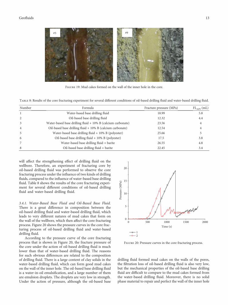
Figure 19 shows the mud cakes that formed on the wall ofthe inner hole in the core under two conditions. It is apparentthat the thickness of the mud cakes that formed in the innerhole is greater than before the drilling fluid was weighted.The solid phase content of the mud cakes is also much higherthan before the drilling fluid was weighted. Moreover, themud cakes are pressed tightly and compactly, which partlyconfirms the mechanism for the apparent bending of thepressure curve.
3.4. Difference between the Effects of Water-Based DrillingFluid and Oil-Based Drilling Fluid on Core Fracturing. Inrecent years, the application of oil-based drilling fluid inChina has increased, and there are some essential differencesbetween oil-based drilling fluid and water-based drillingfluid. There are also some differences between the changesin hydrophilic formation rocks that are caused bywater-based drilling fluid and oil-based drilling fluid. Thedifferences between the composition of oil base drilling fluidand the composition of water-based drilling fluid lead to verydifferent natures of resulting mud cakes. All of these aspects
0 500 1000 1500 2000 2500 30000
5
10
15
20
25
Pres
sure
(MPa
)
Time (s)
18
Figure 16: Pressure curves in the core fracturing process.
0 500 1000 1500 2000 25000
5
10
15
20
25
30
Pres
sure
(MPa
)
Time (s)
5617
Figure 17: Pressure curves in the core fracturing process.
0 500 1000 1500 2000 2500 30000
5
10
15
20
25
30
Pres
sure
(MPa
)
Time (s)
59
Figure 18: Pressure curves in the core fracturing process.
12 Geofluids
will affect the strengthening effect of drilling fluid on thewellbore. Therefore, an experiment of fracturing core byoil-based drilling fluid was performed to observe the corefracturing process under the influence of two kinds of drillingfluids, compared to the influence of water-based base drillingfluid. Table 8 shows the results of the core fracturing experi-ment for several different conditions of oil-based drillingfluid and water-based drilling fluid.
3.4.1. Water-Based Base Fluid and Oil-Based Base Fluid.There is a great difference in composition between theoil-based drilling fluid and water-based drilling fluid, whichleads to very different natures of mud cakes that form onthe wall of the wellbore, which then affect the core fracturingprocess. Figure 20 shows the pressure curves in the core frac-turing process of oil-based drilling fluid and water-baseddrilling fluid.
According to the pressure curve of the core fracturingprocess that is shown in Figure 20, the fracture pressure ofthe core under the action of oil-based drilling fluid is muchlower than that of water-based drilling fluid. The reasonsfor such obvious differences are related to the compositionof drilling fluid. There is a large content of clay solids in thewater-based drilling fluid, which can form good mud cakeson the wall of the inner hole. The oil-based base drilling fluidis a water-in-oil emulsification, and a large number of themare emulsion droplets. The droplets are very low in strength.Under the action of pressure, although the oil-based base
drilling fluid formed mud cakes on the walls of the pores,the filtration loss of oil-based drilling fluid is also very low,but the mechanical properties of the oil-based base drillingfluid are difficult to compare to the mud cakes formed fromthe water-based drilling fluid. Moreover, there is no solidphase material to repair and perfect the wall of the inner hole
#5 #9
Figure 19: Mud cakes formed on the wall of the inner hole in the core.
Table 8: Results of the core fracturing experiment for several different conditions of oil-based drilling fluid and water-based drilling fluid.
Number Formula Fracture pressure (MPa) FLAPI (mL)
1 Water-based base drilling fluid 18.99 5.8
2 Oil-based base drilling fluid 12.32 4.4
3 Water-based base drilling fluid + 10% B (calcium carbonate) 23.56 4
4 Oil-based base drilling fluid + 10% B (calcium carbonate) 12.54 4
5 Water-based base drilling fluid + 10% B (polyester) 25.66 5
6 Oil-based base drilling fluid + 10% B (polyester) 17.5 3.8
7 Water-based base drilling fluid + barite 26.55 4.8
8 Oil-based base drilling fluid + barite 22.45 3.4
0 500 1000 1500 20000
5
10
15
20
Pres
sure
(MPa
)
Time (s)
12
Figure 20: Pressure curves in the core fracturing process.
13Geofluids

in the core in the oil-based drilling fluid, and the differencesin the mud cakes ultimately result in a large difference in thecore fracture pressure of the two drilling fluid systems.
3.4.2. After the Addition of Particulate Materials. The fracturepressure of core under the action of oil-based drilling fluid islow. Plugging materials were added to the oil-based basedrilling fluid to improve the composition of the oil-baseddrilling fluid, to increase the solid phase content in the mudcakes, and to improve the performance of the mud cakes.This was done to investigate whether the fracture pressureof the core can be improved by adding plugging materialsand to compare to the results of water-based drilling fluid.Figure 21 shows the pressure curves of several drilling fluidswith different plugging materials in the core fracturing pro-cess. It is apparent from the pressure curves that the fracturepressure of the core in the water-based drilling fluid is stillsignificantly higher than that of the core in the oil-based dril-ling fluid after plugging material was added. The fracturepressure of the core under the action of the oil-based drillingfluid with calcium carbonate is 12.54MPa, but the fracturepressure of the core under the action of the oil-based basedrilling fluid is 12.32MPa, which shows that the addition ofcalcium carbonate did not improve the effect of theoil-based drilling fluid on strengthening the wellbore. Inaddition, the fracture pressure of the core under the actionof the oil-based drilling fluid with polyester is greatlyimproved. Although the fracture pressure value is not as highas that of the water-based drilling fluid, the effect is very sim-ilar to that of the water-based drilling fluid, which can with-stand higher pressure without immediate damage after thecore is fractured. Calcium carbonate and polyester materialsare very different when added to the oil-based drilling fluid.The effect of polyester materials is better than that of calciumcarbonate, which may be related to the compatibility of poly-ester materials and oil-based drilling fluid and the highstrength of polyester materials.
3.4.3. After Aggravation of the Drilling Fluid. To increasethe density of the drilling fluid to meet the requirementsof different formations, it is necessary to add weightedmaterials to the drilling fluid. Especially for oil-based dril-ling fluid, barite has a great influence. The water-based dril-ling fluid and oil-based drilling fluid were each weighted to1.6 g/cm3, and the core fracturing experiment was per-formed to investigate the influence of weighted drillingfluid on the core fracturing process. Figure 22 shows theresulting pressure curves.
From the experimental results, it is apparent that whetherwater-based drilling fluid or oil-based drilling fluid is used,compared to the base drilling fluid, when barite is added, itobviously improves the fracture pressure of the core. At thesame time, the fracture pressure of the core in the presenceof water-based drilling fluid is still greater than that ofoil-based drilling fluid. It was found that there is a significantdifference between the slopes of the pressure curves in thecore under the action of both kinds of drilling fluid. In thepresence of oil-based drilling fluid, the slope of the curve isstable. However, in the presence of water-based drilling fluid,
the curve is obviously bent, and the slope of the pressurecurve is gradually reduced. The change in the curve reflectsthe influence of drilling fluid on the core fracturing process.The deformation ability of mud cakes formed by thewater-based drilling fluid is better than that of mud cakesformed by the oil-based drilling fluid under the action ofpressure. The change in mud cakes also slowed the core frac-turing process. Therefore, improving the mechanical proper-ties of mud cakes formed by the oil-based drilling fluid canimprove the effect of oil-based drilling fluid on strengtheningthe wellbore.
3.5. Analysis of Core Fracturing Curve Characteristics.Through a large number of intact core fracturing experiments,
0 500 1000 1500 2000 2500 30000
5
10
15
20
25
30
Pres
sure
(MPa
)
Time (s)
3456
Figure 21: Pressure curves in the core fracturing process.
0 500 1000 1500 2000 2500 30000
5
10
15
20
25
30
Pres
sure
(MPa
)
Time (s)
78
Figure 22: Pressure curves in the core fracturing process.
14 Geofluids

it is found that the composition of drilling fluid, the particlesize distribution of the plugging materials, the performanceof the materials, and other parameters have great influenceon the core fracturing process. Because drilling fluid is a verycomplex decentralized system, the core fracturing process isextremely complicated under the action of drilling fluid. Alarge number of core fracturing experiments have also con-firmed that a change in composition of drilling fluid canhave a significant impact on the core fracturing process.The core fracturing process differs in the presence of differ-ent drilling fluids, and the associated pressure curves haveunique characteristics. However, there are some commoncharacteristics. Based on the analysis and summary of allcharacteristics of the pressure curves, some commonalitiesand characteristics of the core fracturing process aredescribed. The understanding of the details of core fractur-ing is strengthened, and characteristics associated with dif-ferent situations are different, which provides reference forselecting plugging materials.
3.5.1. Analysis of Integral Fracturing Curves. In the experi-ments, pressure change curves from the inner hole of the corewere obtained. The pressure curves for different drillingfluids and different plugging materials also differ. The frac-ture curve of one experiment is selected, and some commoncharacteristics of the whole core fracturing process are ana-lysed, as shown in Figure 22. According to the curve analysisin Figure 23, the entire core fracturing process can be dividedinto five stages.
(1) Initial formation stage of the mud cakes: at this stage,with the drilling fluid continuously pumped into thecore, the drilling fluid gradually forms mud cakeson the wall of the inner hole of the core under theaction of pressure. The mud cakes then reach stabil-ity. At this stage, the pressure changes with time,and the pressure value in the core exceeds the confin-ing pressure.
(2) Resilient-plastic deformation stage of the core andmud cakes: with the stability of the mud cakes, themud cakes have a certain thickness and permeability.Pressure builds up rapidly in the core, and the pres-sure curve is basically a straight line until a pointwhen the curve begins to bend, which indicates thatfractures begin to appear in the core. Then, the frac-tures gradually expand as the pressure continues toincrease.
(3) Stable development stage of the fractures: after thefractures appear in the core, the core does not frac-ture completely. The fractures propagate stably underpressure, which is a controllable stage. At this stage,the pressure in the core continues to increase underthe action of the mud cakes.
(4) Unstable development stage of the fractures: withthe propagation of the fractures, the pluggingmaterials had difficulty plugging the fractures sta-bly. The pressure inside the core fluctuated greatly,
and the propagation of fractures gradually devel-oped to an uncontrollable stage, and the core even-tually fractured.
(5) Unstable plugging stage: the core was completelyfractured, and fractures with a certain width wereformed. The solid phase in the drilling fluid still hada certain ability to plug fractures. Only the gradation,concentration, and properties of the materials weredifferent, and therefore, their ability to plug fractureswas different.
To strengthen the wellbore, it is necessary to improve themaximum of the second stage, to prolong the stable time ofthe third stage, and to control the unstable development ofthe fourth stage by adjusting the drilling fluid and addingplugging materials. After fracturing of the core, the corecan still have formation pressure-bearing capacity underthe action of plugging materials.
3.5.2. Some Kinds of Fracturing Curves. In the core fracturingexperiment, based on the statistics of pressure curves, not allof the curves included all of the processes mentioned above.Some experiments may lack a stage, showing characteristicsthat can be roughly classified into four types of pressurecurves, as shown in Figure 24.
The curves shown in Figure 24 reflect the moment of corefracturing and the interactions between the drilling fluid andthe core after the core fractured. In the first type of curve,with fracture of the core, the pressure of the inner hole inthe core rapidly decreases to the confining pressure value. Itis maintained near the confining pressure value, and the pres-sure curve is smooth. The second and third types of curvesare the same as the first type. The difference is the pressureresponse in the core after the core is fractured. The pressurein the core will continue to increase under the action of dril-ling fluid. Then, it decreases to a certain value and shows azig-zag pattern. The difference between the two is the magni-tude of the zig-zag. The size of the zig-zag reflects the abilityof the drilling fluid to plug the fractures that formed on the
Resilient-plasticdeformation stage ofcore and mud cakes
Pres
sure
(MPa
)
Time (s)
Initialformation
stage ofmudcakes
Stabledevelop-
mentstage of
fractures
Unstabledevelop-
mentstage of
fractures
Unstableplugging
stage
A
Figure 23: Changes in the core fracturing process.
15Geofluids
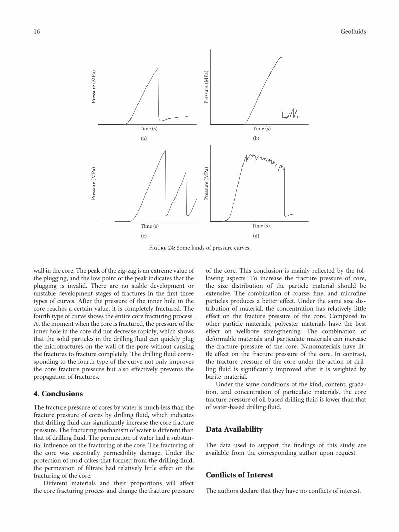
wall in the core. The peak of the zig-zag is an extreme value ofthe plugging, and the low point of the peak indicates that theplugging is invalid. There are no stable development orunstable development stages of fractures in the first threetypes of curves. After the pressure of the inner hole in thecore reaches a certain value, it is completely fractured. Thefourth type of curve shows the entire core fracturing process.At the moment when the core is fractured, the pressure of theinner hole in the core did not decrease rapidly, which showsthat the solid particles in the drilling fluid can quickly plugthe microfractures on the wall of the pore without causingthe fractures to fracture completely. The drilling fluid corre-sponding to the fourth type of the curve not only improvesthe core fracture pressure but also effectively prevents thepropagation of fractures.
4. Conclusions
The fracture pressure of cores by water is much less than thefracture pressure of cores by drilling fluid, which indicatesthat drilling fluid can significantly increase the core fracturepressure. The fracturing mechanism of water is different thanthat of drilling fluid. The permeation of water had a substan-tial influence on the fracturing of the core. The fracturing ofthe core was essentially permeability damage. Under theprotection of mud cakes that formed from the drilling fluid,the permeation of filtrate had relatively little effect on thefracturing of the core.
Different materials and their proportions will affectthe core fracturing process and change the fracture pressure
of the core. This conclusion is mainly reflected by the fol-lowing aspects. To increase the fracture pressure of core,the size distribution of the particle material should beextensive. The combination of coarse, fine, and microfineparticles produces a better effect. Under the same size dis-tribution of material, the concentration has relatively littleeffect on the fracture pressure of the core. Compared toother particle materials, polyester materials have the besteffect on wellbore strengthening. The combination ofdeformable materials and particulate materials can increasethe fracture pressure of the core. Nanomaterials have lit-tle effect on the fracture pressure of the core. In contrast,the fracture pressure of the core under the action of dril-ling fluid is significantly improved after it is weighted bybarite material.
Under the same conditions of the kind, content, grada-tion, and concentration of particulate materials, the corefracture pressure of oil-based drilling fluid is lower than thatof water-based drilling fluid.
Data Availability
The data used to support the findings of this study areavailable from the corresponding author upon request.
Conflicts of Interest
The authors declare that they have no conflicts of interest.
Pres
sure
(MPa
)
Time (s)
(a)
Pres
sure
(MPa
)
Time (s)
(b)
Pres
sure
(MPa
)
Time (s)
(c)
Pres
sure
(MPa
)
Time (s)
(d)
Figure 24: Some kinds of pressure curves.
16 Geofluids
Acknowledgments
The authors are grateful for the support from the State KeyLaboratory of Oil and Gas Reservoir Geology and Exploita-tion, Southwest Petroleum University, and the NationalProgram on Key Basic Research Project (973 Program,Registration No. 2013CB228003).
References
[1] T. Xu, Y. Liu, and W. Shen, The Leak Prevention and PluggingTechnology of Drilling Engineering, Petroleum Industry Press,Beijing, 1997.
[2] D. Gao, Deep and Ultra-Deep Well Drilling Technology in theComplex Geological Conditions, Petroleum Industry Press,Beijing, 2004.
[3] P. Wang and Y. Bai, The Principle of Drilling Fluid Technologyfor Deep Well and Ultra-Deep Well, Petroleum Industry Press,Beijing, 2014.
[4] E. Therond, S. Taoutaou, S. G. James, P. W. Way, P. Gomes,and A. Dondale, “Understanding lost circulation whilecementing: field study and laboratory research,” SPE Drilling& Completion, vol. 33, no. 1, pp. 77–86, 2018.
[5] D. L.Whitfill, D. E. Jamison, M.Wang, and A. Angove-Rogers,“Preventing lost circulation requires planning ahead,” in Inter-national Oil Conference and Exhibition in Mexico, Veracruz,Mexico, June 2007.
[6] T. M. Nayberg, “Laboratory study of lost circulation materialsfor use in both oil-based and water-based drilling muds,” inSPE/IADC Drilling Conference, Dallas, TX, USA, 1987.
[7] M. Alsaba and R. Nygaard, “Review of lost circulation mate-rials and treatments with an updated classification,” in AADEFluids Technical Conference and Exhibition, American Associ-ation of Drilling Engineers, Houston, TX, USA, 2014.
[8] M. Jeennakorn, R. Nygaard, O.-M. Nes, and A. Saasen, “Test-ing conditions make a difference when testing LCM,” Journalof Natural Gas Science and Engineering, vol. 46, pp. 375–386,2017.
[9] G. Alshubbar, R. Nygaard, and M. Jeennakorn, “The effect ofwellbore circulation on building an LCM bridge at the fractureaperture,” Journal of Petroleum Science and Engineering,vol. 165, pp. 550–556, 2018.
[10] A. Tehrani, J. Friedheim, J. Cameron, and B. Reid, “Designingfluids for wellbore strengthening – is it an art?,” in AADENational Technical Conference and Exhibition, American Asso-ciation of Drilling Engineers, Houston, TX, USA, 2007.
[11] H. Wang, Near Wellbore Stress Analysis for Wellbore Strength-eningDepartment of Chemical and Petroleum Engineering,University of Wyoming, Laramie, WY, USA.
[12] H. Wang, B. F. Towler, M. Y. Soliman, and Z. Shan, “Wellborestrengthening without propping fractures: analysis forstrengthening a wellbore by sealing fractures alone,” in Inter-national Petroleum Technology Conference, Kuala Lumpur,Malaysia, December 2008.
[13] J. E. Friedheim, J. E.Arias-Prada,M.W. Sanders, andR. Shursen,“Innovative fiber solution for wellbore strengthening,” inIADC/SPE Drilling Conference and Exhibition, San Diego,CA, USA, March 2012.
[14] O. Contreras, G. Hareland, M. Husein, R. Nygaard, andM. Alsaba, “Wellbore strengthening in sandstones by meansof nanoparticle-based drilling fluids,” in SPE Deepwater
Drilling and Completions Conference, Galveston, TX, USA,September 2014.
[15] C. O. Nwaoji, G. Hareland, M. Husein, R. Nygaard, andM. F. Zakaria, “Wellbore strengthening- nano-particle dril-ling fluid experimental design using hydraulic fracture appa-ratus,” in SPE/IADC Drilling Conference, Amsterdam, TheNetherlands, March 2013.
[16] D. L. Whitfill and T. Hemphill, “All lost-circulation materialsand systems are not created equal,” in SPE Annual TechnicalConference and Exhibition, Denver, CO, USA, October 2003.
[17] A. Kumar, S. Savari, D. Whitfill, and D. E. Jamison, “Wellborestrengthening: the less-studied properties of lost-circulationmaterials,” in SPE Annual Technical Conference and Exhibi-tion, Florence, Italy, September 2010.
[18] A. Kuma, S. Savari, D. E. Jamison, and D. L. Whitfill, “Applica-tion of fiber laden pill for controlling lost circulation in naturalfractures,” in AADE National Technical Conference and Exhi-bition, American Association of Drilling Engineers, Houston,TX, USA, 2011.
[19] S. Savari, D. L. Whitfill, and A. Kumar, “Resilient lost circula-tion material (LCM): a significant factor in effective wellborestrengthening,” in SPE Deepwater Drilling and CompletionsConference, Galveston, TX, USA, June 2012.
[20] A. K. Mansour, A. D. Taleghani, and G. Li, “Smart lost cir-culation materials for wellbore strengthening,” in 51st U.S.Rock Mechanics/Geomechanics Symposium, San Francisco,CA, USA, June 2017.
[21] N. Collins, D. Whitfill, A. Kharitonov, and M. Miller, “Com-prehensive approach to severe loss circulation problems inRussia,” in SPE Russian Oil and Gas Conference and Exhibi-tion, Moscow, Russia, October 2010.
[22] X. Pu, X. Luo, and P. Luo, “The bridge-shielding techniqueused in improving the compressive strength of luohezulost-circulation formation in Changqing Oilfield,” Journal ofSouthwest Petroleum Institute, vol. 17, pp. 78–84, 1995.
[23] Y.Wang, “Technology onmud lost control of severe lost circu-lation and improving formation pressure containment in TaheOilfield,” Drilling Fluid & Completion Fluid, vol. 30, pp. 33–36,2013.
[24] S. Gao, “Leakage control under pressure in Well Yuanba-1,”Petroleum Drilling Techniques, vol. 36, pp. 45–48, 2008.
[25] X. Li, J. Guo, Y. Wang, G. Liu, and S. Sun, “The application ofmud loss control under pressures with gelled LCM in Puguangarea,” Drilling Fluid & Completion Fluid, vol. 25, pp. 53–56,2008.
[26] J. Liu, S. Liu, X. Chen, S. Zhao, and Y. Nie, “Study and applica-tion of pressure bearing and lost circulation technique,”Fault-Block Oil & Gas Field, vol. 18, pp. 116–118, 2011.
[27] H. Zou, L. Yu, Z. Wang, and Y. Tang, “Research on technologyof sealing under high pressure in permian Tuofu block of TaheOilfield,” Drilling Fluid & Completion fluid, vol. 28, pp. 78–80,2011.
[28] S. Li, L. Tian, Y. Xue, G. Liu, and W. Sui, “Hole pluggingtechnology with high-temperature resistance and wellborestrengthening capacity applied in the Xuwen X3 well,” NaturalGas Industry, vol. 31, pp. 73–77, 2011.
[29] M. He, J. Wu, X. Pu et al., “A study of strengthening pluggingbased on the cage structure theory,” Natural Gas Industry,vol. 33, pp. 80–84, 2013.
[30] P. Yang, M. Chen, Y. Jin et al., “Crack pressure bearing capac-ity model and its application to plugging of fractured
17Geofluids

formation,” Chinese Journal of Rock Mechanics and Engineer-ing, vol. 31, pp. 479–487, 2012.
[31] J. Huang, P. Luo, J. Li, S. Wang, G. Zhang, and B. Zhang,“Study on the enhancement of formation bearing resistance,”Drilling Fluid & Completion Fluid, vol. 26, pp. 69–71, 2009.
[32] Z. Yang, X. Wu, X. Wang, J. Zhang, and F. Wu, “Study on mudloss control under pressure with HMXW reticular fiber,” Dril-ling Fluid & Completion Fluid, vol. 31, pp. 36–38, 2014.
[33] J. Zhang, J. Luo, Z. Li, G. Wang, W. Jiang, and J. Zhang, “Pres-surized plugging technology applied in deep high-angle wells,”Natural Gas Industry, vol. 30, pp. 74-75, 2010.
[34] X. Lu, X. Zhao, H. Wang, W. Zhang, and T. Xu, “Applicationof pressure-bearing solidifying LCM for mud loss control infault zones in Bohai oilfield,” Drilling Fluid & CompletionFluid, vol. 31, pp. 47–49, 2014.
[35] R. Majidi, A. Dondale, N. Braley, and R. Flores, “The applica-tion of wellbore strengthening to achieve zonal isolation,” inIADC/SPE Drilling Conference and Exhibition, Fort Worth,TX, USA, March 2018.
[36] C. Falgout and G. D. Stefano, “Solving losses and increasingthe drilling window in depleted zones by continuouslystrengthening the wellbore,” in SPE Annual Technical Confer-ence and Exhibition, San Antonio, TX, USA, October 2017,SPE.
[37] Y. C. Feng and K. E. Gray, “Review of fundamental studies onlost circulation and wellbore strengthening,” Journal of Petro-leum Science and Engineering, vol. 152, pp. 511–522, 2017.
18 Geofluids

Hindawiwww.hindawi.com Volume 2018
Journal of
ChemistryArchaeaHindawiwww.hindawi.com Volume 2018
Marine BiologyJournal of
Hindawiwww.hindawi.com Volume 2018
BiodiversityInternational Journal of
Hindawiwww.hindawi.com Volume 2018
EcologyInternational Journal of
Hindawiwww.hindawi.com Volume 2018
Hindawiwww.hindawi.com
Applied &EnvironmentalSoil Science
Volume 2018
Forestry ResearchInternational Journal of
Hindawiwww.hindawi.com Volume 2018
Hindawiwww.hindawi.com Volume 2018
International Journal of
Geophysics
Environmental and Public Health
Journal of
Hindawiwww.hindawi.com Volume 2018
Hindawiwww.hindawi.com Volume 2018
International Journal of
Microbiology
Hindawiwww.hindawi.com Volume 2018
Public Health Advances in
AgricultureAdvances in
Hindawiwww.hindawi.com Volume 2018
Agronomy
Hindawiwww.hindawi.com Volume 2018
International Journal of
Hindawiwww.hindawi.com Volume 2018
MeteorologyAdvances in
Hindawi Publishing Corporation http://www.hindawi.com Volume 2013Hindawiwww.hindawi.com
The Scientific World Journal
Volume 2018Hindawiwww.hindawi.com Volume 2018
ChemistryAdvances in
Scienti�caHindawiwww.hindawi.com Volume 2018
Hindawiwww.hindawi.com Volume 2018
Geological ResearchJournal of
Analytical ChemistryInternational Journal of
Hindawiwww.hindawi.com Volume 2018
Submit your manuscripts atwww.hindawi.com