laboratory electronic parts management system
TRANSCRIPT

1 | P a g e
UNIVERSITY OF ILLINOIS AT URBANA-CHAMPAIGN | ECE department
Laboratory Electronic Parts Management System ECE445 Spring 2013 Project #31
Design Review
February 26, 2013
Chengcheng Huang & Chao Cao
Prof. Paul Scott Carney
TA: Justine Fortier

2 | P a g e
Table of Contents_____________________________________________________________
1. Introduction..........................................................................................................................3
1.1 Statement of Purpose ....................................................................................................3
1.2 Objectives.......................................................................................................................3
1.2.1 Goals.............................................................................................................3
1.2.2 Functions.......................................................................................................4
1.2.3 Benefits.........................................................................................................4
1.2.4 Features........................................................................................................4
2. Design ..................................................................................................................................5
2.1 Block Diagrams...............................................................................................................5
2.2 Block Descriptions..........................................................................................................8
2.3 Simulation Result.........................................................................................................16
3. Requirements and Verification............................................................................................19
4. Tolerance Analysis.................................................................................................................... 22
5. Cost and Schedule ..............................................................................................................22
4.1 Cost Analysis ..................................................................................................................22
4.2 Schedule ........................................................................................................................ 23
6. Ethical and Safety Considerations ............................................................................................24
5.1 Ethical ...............................................................................................................................24
5.2 Safety................................................................................................................................25
7. References..............................................................................................................................25

3 | P a g e
1. Introduction_______________________________________________________________
1.1 Statement of Purpose The project goal is to design a management system
can be used by teaching assistants or laboratory
managers to collect how many electronic parts such as
chips, I/O boxes, Arduino panels left in the drawers.
This is a both hardware and software based laboratory
management system that offers a set of key features
that support a modern electrical laboratory operation.
Most of current methods to record and modify the
inventory in the laboratory are finished manually by
lab managers. However, this project can do these jobs
automatically. Costumers only need to open a drawer
and enter the number of items changed. This project
will save lab manager a lot of time in counting the
numbers of items in the laboratory.
Fig.1.1 Drawers in ECE445 Lab
1.2 Objectives
1.2.1 Goals:
The project goal is to develop an electric parts drawer system to help the TAs or lab
faculty manage the parts easier and faster. The final product should be a drawer system
with a display LCD screen and numeric keypad with input buttons. Each time when
student/faculty borrow or return part from the a drawer, the system will automatic
detect which drawer is opened and the display will show a message to tell which
electronic part has been chosen and ask to enter the number to borrow or return. And it
will calculate the parts left in each drawer and transmit the data to the Desktop of lab
mangers.

4 | P a g e
1.2.2 Functions:
• System starts to operate when the drawer is open
• Users can enter the amount taken or return through numeric keypad
• Brief instruction of operations will be showed on LCD screen
• The changed amount will be reflected on the Desktop
1.2.3 Benefits:
• New method to manage laboratory parts
• Save time in counting every item in laboratory
• Enables lab manager know which item is out of stock
• Recognize automatically if the drawer is open
1.2.4 Features:
• Integrated database inventory
• User friendly Interface
• Easy operation
• Wireless data transfer

5 | P a g e
2. Design_______________________________________________________________ 2.1 Block Diagrams
2.1.1 Main (Top Level) Diagram
2.1.2 Switch Signal Design Diagram
2.1.3 Keypad Design Diagram
MCU
KEYPAD
LCD SWITCH SIGNAL
POWER
Wireless Transmission
#1 switch
#2 switch
#3 switch
#4 switch
#5 switch
#6 switch
#8 switch
#7 switch
MUX MCU

6 | P a g e
2.1.4 Micro Control Unit (MCU) Design Diagram
2.1.5 Liquid Crystal Display (LCD) Design Diagram
2.1.6 Wireless Transmission Design Diagram
2.1.7 Power Supply Design Diagram
PIC16F887 5V POWER
RESET
Crystal Oscillator
LCD MCU
CONTROL
POWER
MCU UART XBEE
MODUL

7 | P a g e
2.2 Block Descriptions
2.2.1 Switch Signal:
The switch signal module is the first input module of the system. It contains eight drawer-switches and an 8-to-1 MUX (74LS151). This input module will send out I/O signal to MCU to do the next operation.
The basic function of the drawer switch works as simple I/O switch. A metal bar will be placed on each drawer and it will connect the 2 wires on the back of the drawer. The wires of each will be connecting with 5V VCC though a resistor independently. When the drawer is closed, the current go through the metal bar and it acts as the switch turns on. And there will be a signal “1” sent out. When the drawer is opened, the metal bar and wires disconnect, and there will be a signal “0” sent out. To prevent the switch to burn from high current, a 1k-ohm resistor will place through the wire as the Fig.2.1 show below to reduce the current trough the switch. (In order to make sure the metal bar and wire connect will when the drawer is closed. Some brush wires will be added to the metal bar and wires show as Fig.2.1)
Fig.2.1 Top view of drawer switch module:
120V/5V 1A AC to DC
Converter
5V/3.3V DC to DC
Converter
5V 3.3V
5V

8 | P a g e
The 8 to 1 MUX is using to tell the MCU which drawer is open, the basic function is working as following: MCU sent out the 3-bit select signal (A0, A1, A2) incrementally (000,001…111) on a high frequency to the MUX. And it will also receive an output signal from MUX, which working as drawer status detector. When it detect the “0” signal from MUX, it will know which drawer is open and do the operations, when there is no drawer open or more than one drawer is opened, the MCU will also detected these status.
Fig.2.2 Schematic for the switch and MUX:
2.2.2 Keypad:
The keypad module is the second input module of the system. It is a 4*3 keypad which contains 12 buttons working as same function as I/O switches. 10 of them are the numerical buttons (0 to 9) to enter the electrical parts to check in/out, and other two buttons are “Check In” and “Check Out” buttons. It has 3+4=7 pins connect to the MCU showing as the schematic below (Fig.2.2). By the scanning program on the MCU (similar as the scanning function of drawer-swatch part), the system will receive the signal from the button and do the next step operation.

9 | P a g e
Fig.2.3 Schematic for the keypad:
Fig.2.4 Simulation model for the keypad:
2.2.3 Micro Control Unit (MCU):
For this project, the microcontroller, PIC16F887 will be used for the main control unit. It will connect with crystal oscillator and reset circuit (these are the basic component of MCU) showing in the fig.2.5 below. This module is the core of the system. All the input signals will

10 | P a g e
be process in the MCU. And after do the operations by the program in the MCU, the MCU will sent out the signal trough the UART to LCD to display the message and sent the data out through the XBEE wireless transmission to the computer. The idea of the MCU working function this like this: after connect the MCU with power supply (5V VCC), it will first initialize the UART and do the initialize set up with LCD and XBEE. After initialize, MCU will enter to the main program cycle; it will automatically and constantly scan the signal from the drawer switches and keypad. When the MCU detect there is drawer open, it will sent signal to LCD to show the message and wait to receive the signal from keypad. When the MCU receive the correct input signal from the keypad buttons, it will send the data through the XBEE to the computer.
The Flowchart of the MCU working process:
Start
MCU Initialization
LCD Initialization
XBEE Setup
Drawer Open
Correct Input from Keypad
Calculate the enter value, Process the Input
Data, and Transmit
Process Result and Display
Y N
Y
N

11 | P a g e
Fig.2.5 Schematic for MCU:
2.2.4 Liquid Crystal Display (LCD):
For this project, a 128*64 LCD monitor (LCM12864, see Fig.2.4) will be used to display the message on the user interface. It connects with the MCU with 8 data bus lines, showing in Fig.2.7. The LCM has its own control unit and character library, so the MCU can drive LCD by communicate with the LCD control unit directly. There will be 10 different messages showing on this LCD in different status: if all the drawers are closed, the message display on LCD will be “No drawer open, please open one to get start.”; if one of the drawers is opened, the message display will be “Drawer X has been selected, please enter the number you wish to check in or check out.” (In this message, X is the number of the open drawer, since there will be 8 drawer-switches in this project, so the LCD have 8 drawer open message); if more than one drawers open at the same time, the message display will be “Please open one drawer each time, thanks.”
Fig.2.6 Outline Dimensions for LCD:

12 | P a g e
Fig.2.7 Schematic for LCD:

13 | P a g e
2.2.5 Wireless Signal transmission
Consider the situation that there are a lot of wires distributed in the modern laboratory, this project apply a wireless signal transfer technology through XBee Modules. Moreover, in order to get a stronger signal and transfer a longer distance, this project choose to use the XBee PRO. There will be totally two XBee PRO applied in the project, one works as a transmitter and the other works as a receiver. For the connection with the MCU data output, adaptors will be applied to the XBee. The adapter contains two 1x10 pin headers with sockets on one side and pins on the other side (female header). It also contains a 1x8 header with pins on both side (male header).It will provide 6 outputs used to connect XBEE to computer through a FTDI cable, as stated in the following figure.
Figure 2.8 XBee Module with FTDI cable
For the receiver XBee, this project will set it up by plugging in the FTDI cable, USB adapter, Arduino, etc. Under windows, check the device manager, look for "USB Serial Port"

14 | P a g e
Figure 2.9 Schematic for XBee Module:
2.2.6 Power Supply
There are two different standards for the power supply in this project. One is 5V, 1A DC and the other is 3.3V DC. The only part of this project that needs 3.3V DC power supply is the XBee PRO Module. This can be solved by a 5V to 3.3V DC regulator. For the other parts of this project, 5V DC power supply is offered through an 120V AC to 5V,1A DC converter as the following figure.
Figure 2.9 120V AC to 5V,1A DC converter

15 | P a g e
Figure 2.10 Schematic for Power
2.2.7 Computer inventory
In order to build the inventory, this project is designed to use a database software named mySQL. Base on the signal received from MCU output, which shows the information of the variation of amount in each item, the MySQL database will automatically change the inventory table. Besides, this project use the Desktop in the laboratory as the server for the database of the inventory, it can offer a place where to store and fetch the data. After each operation, MySQL will produce a hardcopy of the most recently modified inventory on the desktop of the Computer. Therefore, next time when the drawer is open, MySQL will automatically open this hardcopy and be ready to accept any modification of the inventory table.

16 | P a g e
2.3 Simulation Results:
Here is the simulation model for the system:
Simulation 1

17 | P a g e
Simulation 2
Simulation 3
Simulation 4

18 | P a g e
Simulation 5

19 | P a g e
3. Requirements and Verifications______________________________________
3.1 Switch Signal:
Requirements Verifications 1) Each drawer switch sends out the I/O
signal correctly. 2) Each drawer switch controls its own
output pin independently. 3) MUX chip (74LS151) should work
correctly. 4) The 3-bit select signal sent from MCU
should change correctly with constant frequency.
1) a. Connecting the output pin of each drawer with a multimeter. b. Record the output value of open and close status of this drawer. c. Compare with the requirement output value. (When the drawer is closed, the output voltage should between 4.3V to 5.2V, when the drawer is opened, the voltage should between -0.7V to 0.7V)
2) a. Connecting the output pin of the
testing drawer switch with a multimeter. b. Keep the testing switch in on or off status. c. Turn on or off other switches to see if the output voltage signals of testing switch changes.
3) a. Test the chip on the breadboard with
I/O board. First connecting the chip with 5V Vcc and ground. b. Connecting the input pins and select pins with testing switches on I/O board. c. Make a truth table for the output signal. d. Connecting the output pin of the MUX chip with LED on I/O board. Turn on/off each testing switches, record each output signal and compare with the truth table.
4) After finishing assign the program to the
3-bit select signal to MUX on MCU, connect the 3 pins of the signal to the oscilloscope to check if it’s in correct value and frequency.

20 | P a g e
3.2 Keypad:
Requirements Verifications 1) Each button of the keypad working
correctly.
1) To check if each button working correctly: a. Connecting the 3 column pins with
LED on I/O board. b. Then connecting 1 of 4 row pins
with 5V Vcc. Push each buttons on the power connecting row and check the change of LED light to see if it’s working correctly. (Only one row pin can be connected with Vcc each time to make sure there’s no other row power input to affect the result.) Check all the buttons row by row.
3.3 MCU:
Requirements Verifications 1) Get familiar with PIC working function
(Complete PIC tutorial) 2) Connect each pin correctly. 3) All the programs should work in correct
function. 4) The data transmit to XBEE and LCD
should have correct transmission control protocol.
5) Right power supply. (5V (±0.5 V) 1A AC)
1) Do some easy programing on PIC, such as light up an LED within the tutorial
2) Make sure finish all the simulations and check all the circuits before building the PCB board.
3) After setup all connection of MCU. Test
the program functions step by step. a. Make sure MCU can detect each
drawer-switch input correctly. b. Make sure each output to LCD can
display right message. c. Each button on keypad should input
right data and MCU could calculate the numerical value of input data.
4) After setting up the transmission control
protocol. Check if the message can display on LCD and transmit to Computer through XBEE (Through UART)
5) See power supply part.

21 | P a g e
3.4 LCD:
Requirements Verifications 1) Connect each pin correctly 2) Successful connecting and recognize the
data sent from MCU.
1) Before connect the input pins, check the interface pin connections from the data sheet and get know the role of each pin
2)
a. Make sure each input connects to right pin.
b. Check each display on LCD after do the
display programing. Each message should match right drawer-switch.
3.4 Wireless signal Transmittion:
Requirements Verifications 1) Connect each pin in XBee correctly 2) The XBEE module should function
appropriately on an adapter with 3.3V (±0.5V) VCC from voltage regulator
3) The receiver should be able to received signal efficiently 25m (±5m) away from the transmitter.
1) Before connect the input pins, check the interface pin connections from the data sheet of XBee and get know the role of each pin
2) a. Verify the input VCC produced by voltage regulator using multimeter. b. Connect output pin 1-6 on adapter header to FTDI connector, the XBEE should be able to be Programmed on computer.
3) Make a bunch of test code and put them into the transmitter. Put the receiver about 25m away from the transmitter and look at if it does receive the test code.
3.5 Power Supply:
Requirements Verifications

22 | P a g e
1) 120V AC to 5V, 1A DC converter will offer the most of this project power supply 5V (±0.5 V).
2) LD1117 voltage regulators need to
convert 9V to 3.3V (±0.5 V), which is the voltage require for the XBee operation
1) Measure the voltage across battery by multimeter.
2) Build voltage regulator circuit on
breadboard with 5V VCC, measure the output voltage using
multimeter.
3.6 Computer Inventory:
Requirements Verifications 1) Respond to the signal received by XBee
correctly 2) Change the inventory automatically
when MySQL is open
3) After each operation, store a hard copy
of data on the desktop
1) Use several test data to check the accuracy of the code programmed
2) Use several test data and see the
simulation result to check the inventory changes correctly
3) Open the desktop folder and load the
data saved from last time and compare to the data record in last time.
Tolerance Analysis
4. Tolerance Analysis ___________________________________________
The most important part of this project will be the output signal from each drawer. Because the output signal from the MUX is directly dependent on the output of each drawer. If it goes wrong; much more error will be caused on next stage. So before connecting the drawer switch to the MCU, a careful inspection is needed to checking the error of output bits from each drawer(Use the multimeter connect each output of drawers and check one by one carefully), to ensure system operate correct.
Another important part for the system is the transmission control protocol between the MCU to LCD and XBEE, a careful debugging is needed to ensure it can transmit the correct signal.
5. Cost and Schedule___________________________________________
5.1 Cost Analysis
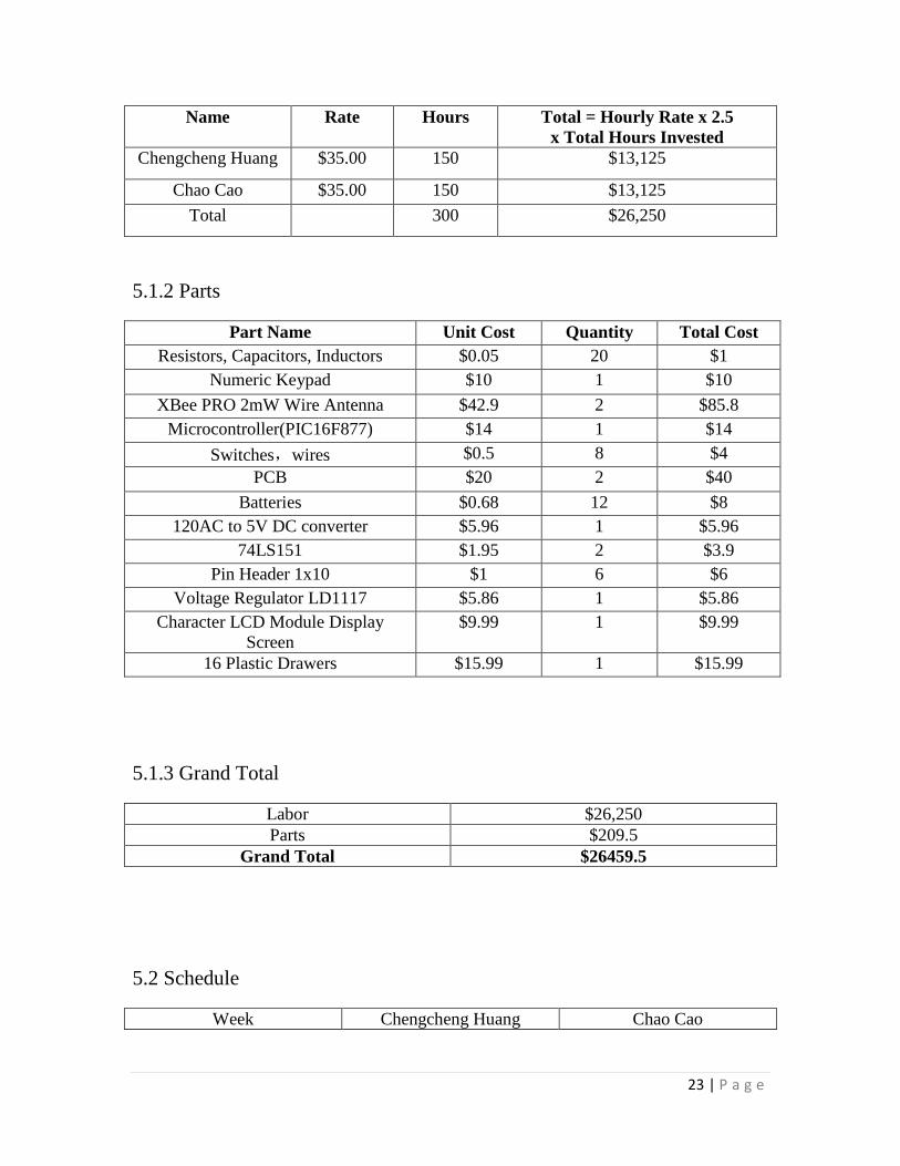
5.1.1 Labor
23 | P a g e
Name Rate Hours Total = Hourly Rate x 2.5 x Total Hours Invested
Chengcheng Huang $35.00 150 $13,125 Chao Cao $35.00 150 $13,125
Total 300 $26,250
5.1.2 Parts
Part Name Unit Cost Quantity Total Cost Resistors, Capacitors, Inductors $0.05 20 $1
Numeric Keypad $10 1 $10 XBee PRO 2mW Wire Antenna $42.9 2 $85.8
Microcontroller(PIC16F877) $14 1 $14 Switches,wires $0.5 8 $4
PCB $20 2 $40 Batteries $0.68 12 $8
120AC to 5V DC converter $5.96 1 $5.96 74LS151 $1.95 2 $3.9
Pin Header 1x10 $1 6 $6 Voltage Regulator LD1117 $5.86 1 $5.86
Character LCD Module Display Screen
$9.99 1 $9.99
16 Plastic Drawers $15.99 1 $15.99
5.1.3 Grand Total
Labor $26,250 Parts $209.5
Grand Total $26459.5
5.2 Schedule
Week Chengcheng Huang Chao Cao

24 | P a g e
2/4 Proposal: Introduction, Cost and Build Schedule
Proposal: Design, Block Level Requirements and
Verification 2/11 Design preliminary control
and numeric pad Circuit Order parts
Research and learn the Micro-Controller Unit Design Circuit(Eagle)
2/18 Design Review Design PCB
Test basic control circuit on Bread Board
Simulation the system
Design Review Design PCB
Learn how to program PIC
2/25 Figure out how XBee module works
Design preliminary power supply network for the
project
Program into PIC Learn how XBee module
works Figure out numeric pad
output signals 3/4 Program XBee to send the
signal from MCU signal output
Program into PIC Connect the numeric pad
output to XBee 3/11 Program MySQL to
respond to the inventory according to signals
Program into PIC Make sure the output
signals work
3/18 Spring Break Spring Break 3/25 Integrate and assembling
the wireless signal transmission parts
Integrate and assembling the MCU and kepad parts
4/1 Testing and debugging the wireless signal transmission parts
Testing and debugging the MCU and kepad parts
4/8 Testing the whole project Make sure the completion
Last Modification of Project Fix all remaining issues
4/15 Prepare for Demo, and Final paper
Prepare for the presentation
4/22 Demo Demo 4/29 Presentation and submit the
final paper Presentation Check out
6. Ethical and Safety Considerations________________________________
6.1 Ethical

25 | P a g e
This project is strictly adhere to the statements of the IEEE Code of Ethics [12] that pertain to our project as follows:
• ”1. to accept responsibility in making decisions consistent with the safety, health, and welfare of the public, and to disclose promptly factors that might endanger the public or the environment;” This project is designed to make the laboratory management easier to handle. It bring the lab users conveniences through automatically recording the number of pieces in drawer taken or increased. The whole design is under strict safety requirements, which promises both users and designers the maximum secure operations.
• “ 3. to be honest and realistic in stating claims or estimates based on available data; “ This project will be experimented in practical and realistic environment. The data will be collected as detailed as possible. The formulas used in the design will be calculated iteratively at least three times to make sure that all calculations are accurate. Simulations are also required at the experimental stage.
• “7. to seek, accept, and offer honest criticism of technical work, to acknowledge and correct errors, and to credit properly the contributions of others; “ Since this is a group project, each group member should listen to all constructive and practical suggestions from other group members. This group will gives credits to each group member strictly and fairly depends on how much contribution he/she does.
6.2 Safety
One important requirement for this project is can be built, operated and maintained in a manner that does not harm any people. Some hazards should be eliminated or contained through good engineering design solutions. The designers of this project have already considered the following possible situations which may be dangerous to designers or users.
a. For Designers During the design process, designers should always work under a safe condition. They should be careful when soldiering all the chips together on the PCB board and when connecting to high voltages.
b. For Users During the operation process, there’s nearly no possible dangerous situation that users can encounter when they are using this system. Most of this project works in a low voltage (safe to human-beings) environment.

26 | P a g e
7. References__________________________________________________
1) PIC 16F887 Data sheet
http://ww1.microchip.com/downloads/en/DeviceDoc/41291G.pdf
2) LCM12864 Data Sheet
http://www.aix-mrs.iufm.fr/formations/filieres/ge/data/PIC/PICC/gdm12864a.pdf
3) UART and Bridging Solutions
http://www.exar.com/connectivity/uart-and-bridging-solutions
4) Transmission control protocol
https://tools.ietf.org/html/rfc793
5) XBee Module
http://www.ladyada.net/make/xbee/configure.html