lab name: - · web viewand heat balance calculations on a four stroke, single cylinder diesel...
TRANSCRIPT
ENERGY CONVERSION ENGINEERING LABORATORY
MANUAL
V Semester (10MEL58)
DAYANANDA SAGAR COLLEGE OF ENGINEERINGAccredited by National Assessment & Accreditation Council (NAAC) with ’A’ Grade
(An Autonomous Institution affiliated to Visvesvaraya Technological University, Belagavi &
ISO 9001:2008 Certified)MECHANICAL ENGINEERING DEPARTMENT
SHAVIGE MALLESWARA HILLS, KUMARASWAMY LAYOUTBENGALURU-560078
Image related to Lab (Department wise and lab wise)
Name of the Student :
Semester /Section :
USN :
Batch :
Energy Conversion Engineering Laboratory/10ME58 [2016]
(Backside of cover page)
Vision of the Institute
To impart quality technical education with a focus on Research and Innovation emphasising on Development of Sustainable and Inclusive Technology for the benefit of society.
Mission of the Institute
To provide an environment that enhances creativity and Innovation in pursuit of Excellence.
To nurture teamwork in order to transform individuals as responsible leaders and entrepreneurs.
To train the students to the changing technical scenario and make them to understand the importance of Sustainable and Inclusive technologies.
ME Dept., Dayananda Sagar College of Engineering Bengaluru Page 2
ENERGY CONVERSION ENGINEERING LABORATORY MANUAL
V Semester (10MEL58)
DAYANANDA SAGAR COLLEGE OF ENGINEERING(An Autonomous Institution affiliated to Visvesvaraya Technological University, Belagavi)
MECHANICAL ENGINEERING DEPARTMENTSHAVIGE MALLESWARA HILLS
KUMARASWAMY LAYOUTBENGALURU-560078
Name of the Student :
Semester /Section :
USN :
Batch :
Energy Conversion Engineering Laboratory/10ME58 [2016]
ME Dept., Dayananda Sagar College of Engineering Bengaluru Page 3
Energy Conversion Engineering Laboratory/10ME58 [2016]
DAYANANDA SAGAR COLLEGE OF ENGINEERING(An Autonomous Institution affiliated to Visvesvaraya Technological University, Belagavi)
DEPARTMENT OF MECHANICAL ENGINEERING, BENGALURU-560078
VISION OF THE DEPARTMENT
MISSION OF THE DEPARTMENT
PROGRAMME EDUCATIONAL OBJECTIVES [PEOs]PEO-1:
PEO-2:
PEO-3:
PEO-4:
PROGRAMME SPECIFIC OUTCOMES [PSOs]
PSO-1:
PSO-2:
ME Dept., Dayananda Sagar College of Engineering Bengaluru Page 4
Energy Conversion Engineering Laboratory/10ME58 [2016]
DAYANANDA SAGAR COLLEGE OF ENGINEERING, BENGALURU-560078.(An Autonomous Institution affiliated to Visvesvaraya Technological University, Belagavi)
DEPARTMENT OF MECHANICAL ENGINEERING.
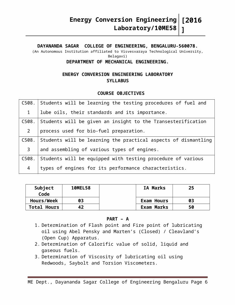
ENERGY CONVERSION ENGINEERING LABORATORYSYLLABUS
COURSE OBJECTIVES
C508.1Students will be learning the testing procedures of fuel and lube oils, their standards and its
importance.
C508.2Students will be given an insight to the Transesterification process used for bio-fuel
preparation.
C508.3Students will be learning the practical aspects of dismantling and assembling of various
types of engines.
C508.4Students will be equipped with testing procedure of various types of engines for its
performance characteristics.
Subject Code 10MEL58 IA Marks 25Hours/Week 03 Exam Hours 03Total Hours 42 Exam Marks 50
PART – A1. Determination of Flash point and Fire point of lubricating oil using Abel Pensky and
Marten’s (Closed) / Cleavland’s (Open Cup) Apparatus.2. Determination of Calorific value of solid, liquid and gaseous fuels.3. Determination of Viscosity of lubricating oil using Redwoods, Saybolt and Torsion
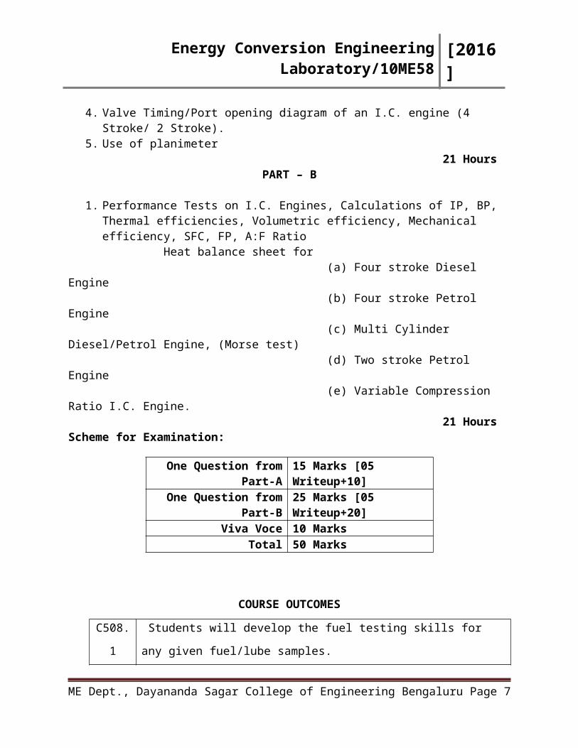
Viscometers.4. Valve Timing/Port opening diagram of an I.C. engine (4 Stroke/ 2 Stroke).5. Use of planimeter
21 HoursPART – B
1. Performance Tests on I.C. Engines, Calculations of IP, BP, Thermal efficiencies, Volumetric efficiency, Mechanical efficiency, SFC, FP, A:F Ratio
Heat balance sheet for (a) Four stroke Diesel Engine (b) Four stroke Petrol Engine (c) Multi Cylinder Diesel/Petrol Engine, (Morse test) (d) Two stroke Petrol Engine (e) Variable Compression Ratio I.C. Engine.
21 Hours
ME Dept., Dayananda Sagar College of Engineering Bengaluru Page 5
Energy Conversion Engineering Laboratory/10ME58 [2016]
Scheme for Examination:
One Question from Part-A 15 Marks [05 Writeup+10]One Question from Part-B 25 Marks [05 Writeup+20]
Viva Voce 10 MarksTotal 50 Marks
COURSE OUTCOMES
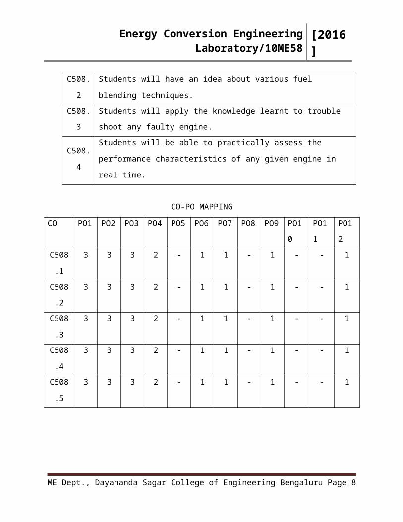
C508.1 Students will develop the fuel testing skills for any given fuel/lube samples.
C508.2 Students will have an idea about various fuel blending techniques.
C508.3 Students will apply the knowledge learnt to trouble shoot any faulty engine.
C508.4Students will be able to practically assess the performance characteristics of any
given engine in real time.
CO-PO MAPPING
CO PO1 PO2 PO3 PO4 PO5 PO6 PO7 PO8 PO9 PO10 PO11 PO12
C508.1 3 3 3 2 - 1 1 - 1 - - 1
C508.2 3 3 3 2 - 1 1 - 1 - - 1
C508.3 3 3 3 2 - 1 1 - 1 - - 1
C508.4 3 3 3 2 - 1 1 - 1 - - 1
C508.5 3 3 3 2 - 1 1 - 1 - - 1
ME Dept., Dayananda Sagar College of Engineering Bengaluru Page 6
Energy Conversion Engineering Laboratory/10ME58 [2016]
DAYANANDA SAGAR COLLEGE OF ENGINEERINGDEPARTMENT OF MECHANICAL ENGINEERING
BENGALURU – 560078
Experiment No:________ Date:____________
Introduction to Foundry
Experiment No: __________ Date: ____________
ME Dept., Dayananda Sagar College of Engineering Bengaluru Page 7
DO’S:
Lab Dress code with Student’s Identity card should be strictly adhered to,
Ensure proper ventilation by keeping the doors and windows open,
Take the guidance of the faculty and the instructors concerned before starting the
experiments,
Take utmost care while cranking the engine,
Ensure that, water is circulated for Engine cooling and for the Exhaust Gas
Calorimeter,
Ensure that Exhaust Valve of the engine under operation is in OPEN position,
Ensure that the electric supply to the heating devices for the experimental
setups/Test Rigs are Switched OFF once the concerned Experiments are
completed,
Keep sufficient distance from the rotating parts,
In case of fire even of small magnitude, alert the concerned lab authorities and know the usage of a Fire Extinguisher and use the sand kept in case of emergencies.
DONT’S:
Never bring any flame in the vicinity of the inflammable fuels,
Never rest your hands on the equipment or on the display board, because it has fragile
measurement devices like thermometers, manometers, etc…
Do not touch/ handle the experimental setups/Test Rigs without their prior knowledge,
Never overcrowd the experimental setup/Test Rig, Leave sufficient space for the person
cranking the engine to start,
Any unsafe conditions like exposed electrical wires, fuel spilling, fuel leakage, etc…
should be brought to the notice of the concerned lab authorities.
Energy Conversion Engineering Laboratory/10ME58 [2016]
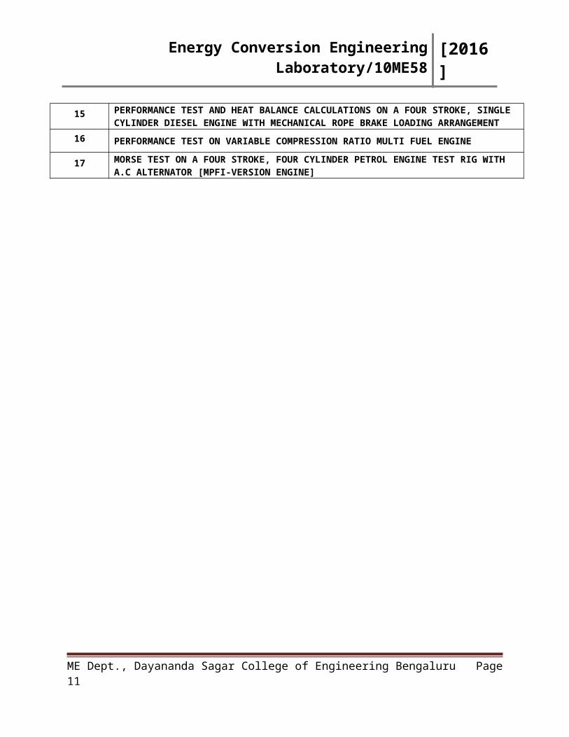
CONTENTS
EXPT NO
NAME OF THE EXPERIMENT
1. FLASH & FIRE POINT OF A GIVEN SAMPLE BY ABEL’S APPARATUS
2 FLASH & FIRE POINT OF A GIVEN SAMPLE BY PENSKY MARTIN APPARATUS
3 FLASH & FIRE POINT OF A GIVEN SAMPLE BY CLEAVLAND OPEN CUP APPARATUS
4. VISCOSITY OF OIL USING REDWOOD VISCOMETER
5. VISCOSITY OF OIL USING SAYBOLT VISCOMETER
6. VISCOSITY OF OIL USING TORSION VISCOMETER
7. CALORIFIC VALUE OF SOLID FUEL- LEWIS THOMSON CALORIMETER
8 CALORIFIC VALUE OF LIQUID FUEL-BOMB CALORIMETER
9. CALORIFIC VALUE OF GASEOUS FUEL-JUNKER’S GAS CALORIMETER
10. VALVE TIMING DIAGRAM-FOUR STROKE ENGINE
11. PORT TIMING DIAGRAM-TWO STROKE ENGINE
12. PLANIMETER
13. PERFORMANCE TEST ON A TWO STROKE PETROL ENGINE
14. PERFORMANCE TEST ON A FOUR STROKE, SINGLE CYLINDER PETROL ENGINE WITH A DC GENERATOR
15PERFORMANCE TEST AND HEAT BALANCE CALCULATIONS ON A FOUR STROKE, SINGLE CYLINDER DIESEL ENGINE WITH MECHANICAL ROPE BRAKE LOADING ARRANGEMENT
16 PERFORMANCE TEST ON VARIABLE COMPRESSION RATIO MULTI FUEL ENGINE
17 MORSE TEST ON A FOUR STROKE, FOUR CYLINDER PETROL ENGINE TEST RIG WITH A.C ALTERNATOR [MPFI-VERSION ENGINE]
ME Dept., Dayananda Sagar College of Engineering Bengaluru Page 8
Energy Conversion Engineering Laboratory/10ME58 [2016]
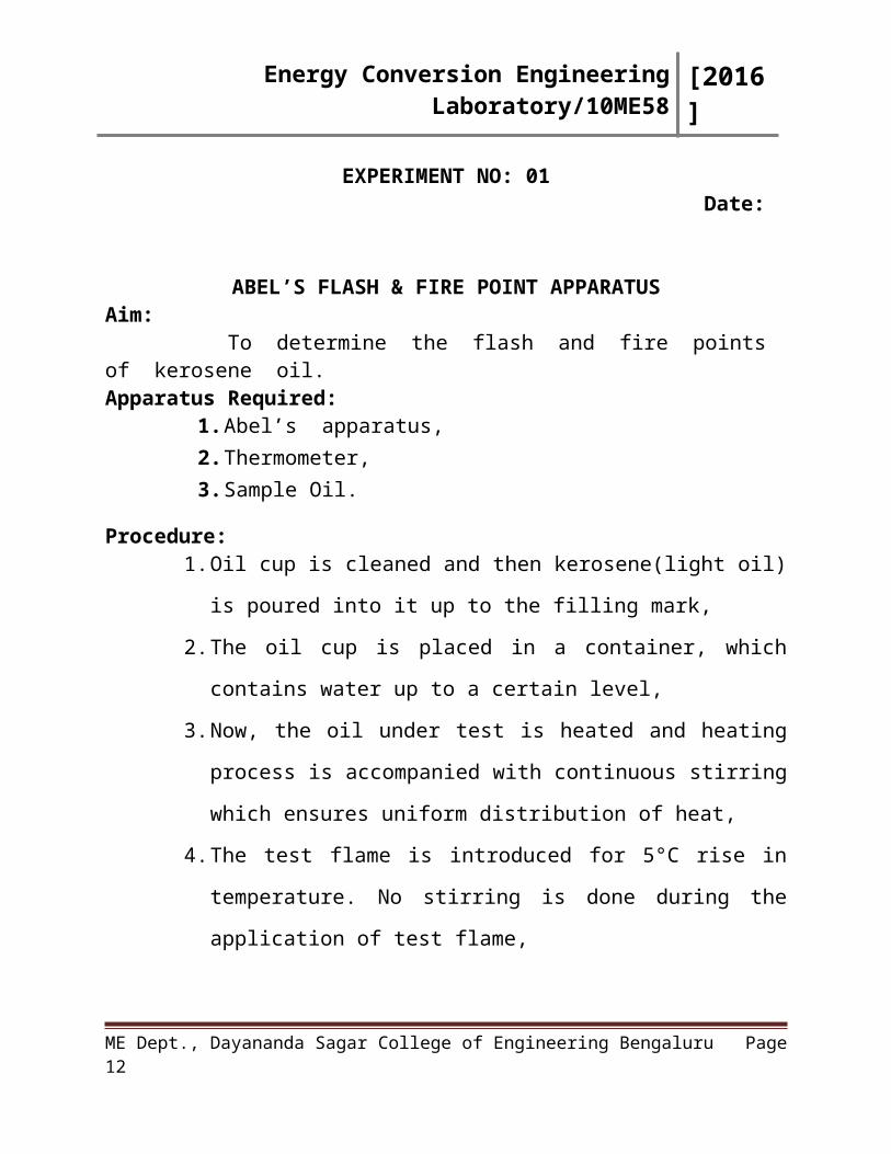
EXPERIMENT NO: 01 Date:
ABEL’S FLASH & FIRE POINT APPARATUSAim: To determine the flash and fire points of kerosene oil.Apparatus Required:
1. Abel’s apparatus, 2. Thermometer,3. Sample Oil.
Procedure:1. Oil cup is cleaned and then kerosene(light oil) is poured into it up to
the filling mark,
2. The oil cup is placed in a container, which contains water up to a
certain level,
3. Now, the oil under test is heated and heating process is accompanied
with continuous stirring which ensures uniform distribution of heat,
4. The test flame is introduced for 5°C rise in temperature. No stirring is
done during the application of test flame,
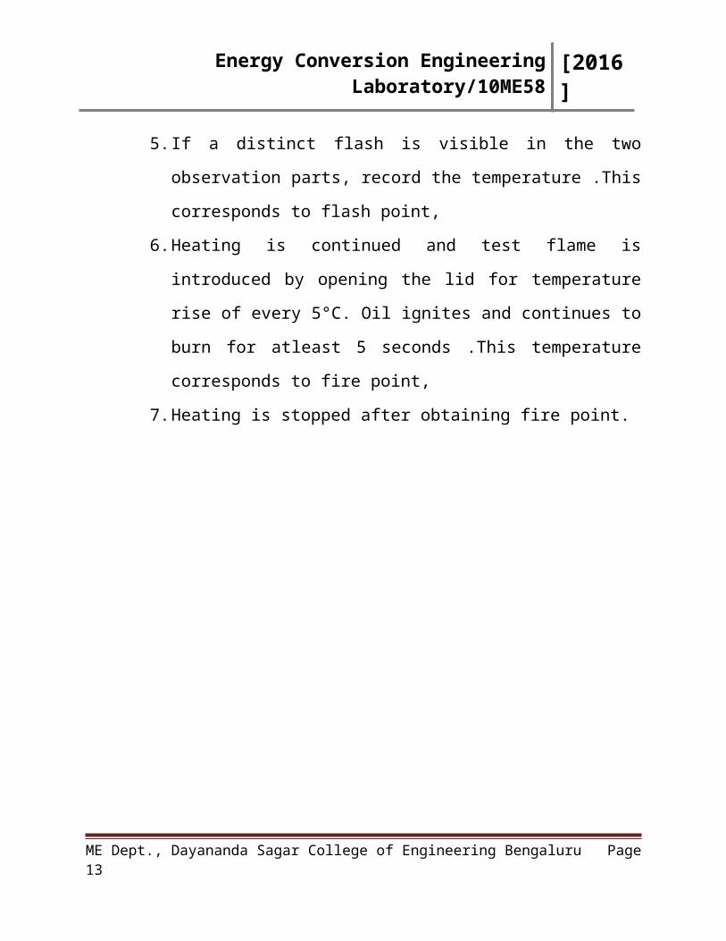
5. If a distinct flash is visible in the two observation parts, record the
temperature .This corresponds to flash point,
6. Heating is continued and test flame is introduced by opening the lid
for temperature rise of every 5°C. Oil ignites and continues to burn for
atleast 5 seconds .This temperature corresponds to fire point,
7. Heating is stopped after obtaining fire point.
ME Dept., Dayananda Sagar College of Engineering Bengaluru Page 9
Energy Conversion Engineering Laboratory/10ME58 [2016]
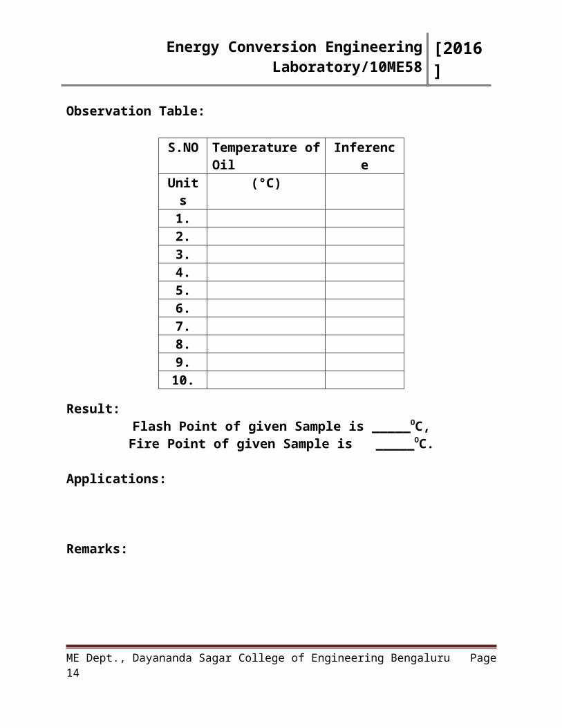
Observation Table:
Result:Flash Point of given Sample is _____OC,Fire Point of given Sample is _____OC.
Applications:
Remarks:
Signature of Staff In-charge with date
ME Dept., Dayananda Sagar College of Engineering Bengaluru Page 10
S.NO Temperature of Oil InferenceUnits (°C)
1.2.3.4.5.6.7.8.9.10.
Energy Conversion Engineering Laboratory/10ME58 [2016]
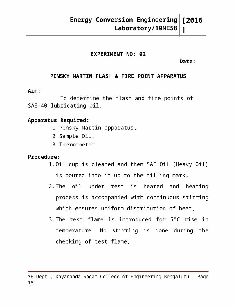
EXPERIMENT NO: 02Date:
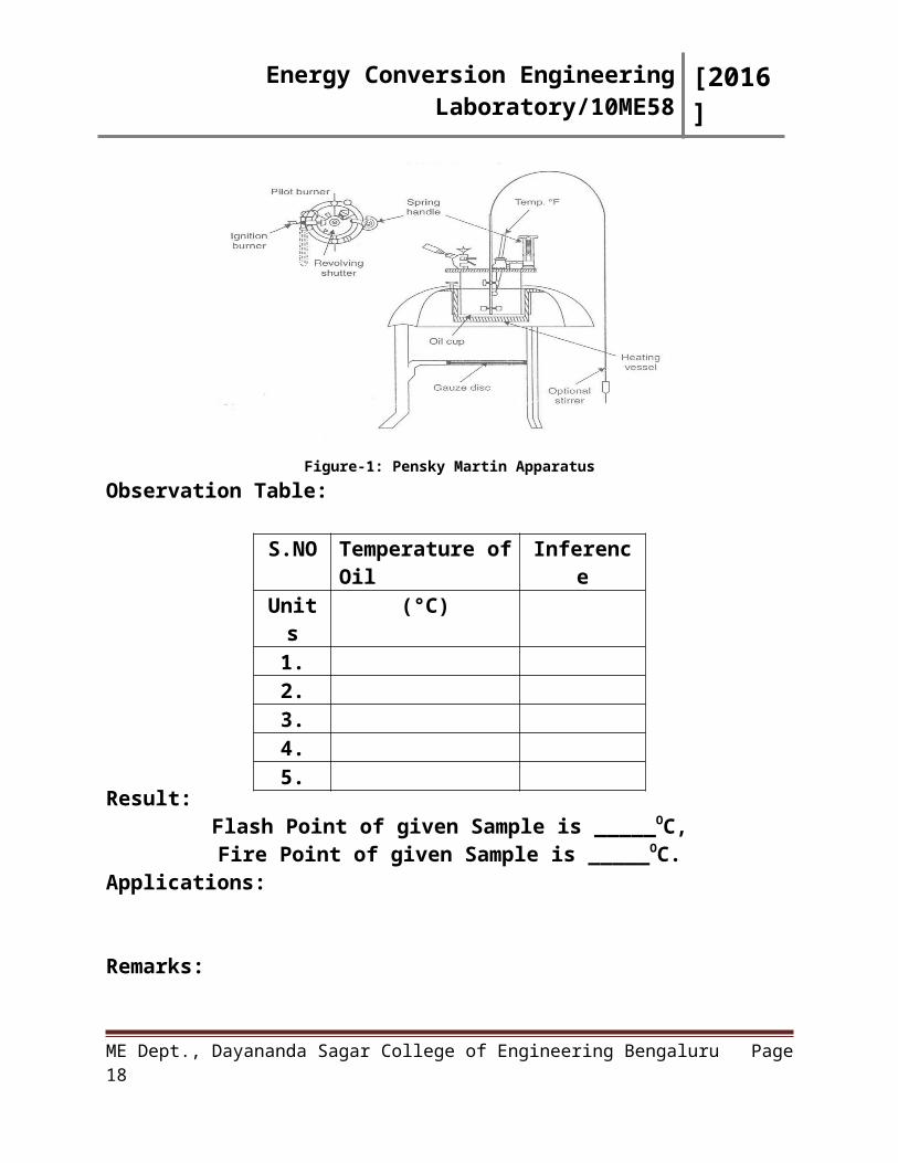
PENSKY MARTIN FLASH & FIRE POINT APPARATUS
Aim: To determine the flash and fire points of SAE-40 lubricating oil.
Apparatus Required:1. Pensky Martin apparatus, 2. Sample Oil, 3. Thermometer.
Procedure:1. Oil cup is cleaned and then SAE Oil (Heavy Oil) is poured into it up
to the filling mark,
2. The oil under test is heated and heating process is accompanied with
continuous stirring which ensures uniform distribution of heat,
3. The test flame is introduced for 5°C rise in temperature. No stirring is
done during the checking of test flame,
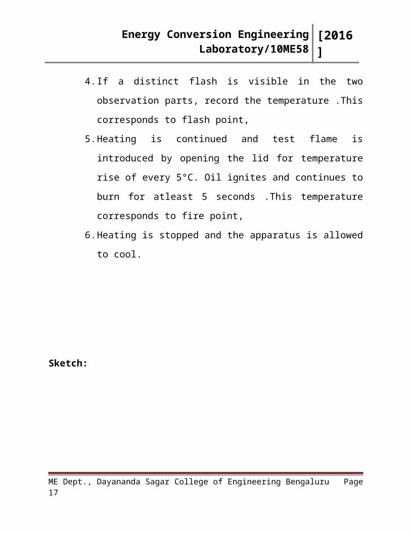
4. If a distinct flash is visible in the two observation parts, record the
temperature .This corresponds to flash point,
5. Heating is continued and test flame is introduced by opening the lid
for temperature rise of every 5°C. Oil ignites and continues to burn for
atleast 5 seconds .This temperature corresponds to fire point,
6. Heating is stopped and the apparatus is allowed to cool.
ME Dept., Dayananda Sagar College of Engineering Bengaluru Page 11
Energy Conversion Engineering Laboratory/10ME58 [2016]
Sketch:
Figure-1: Pensky Martin ApparatusObservation Table:
Result:Flash Point of given Sample is _____OC,Fire Point of given Sample is _____OC.
Applications:
Remarks:
Signature of Staff In-charge with date
ME Dept., Dayananda Sagar College of Engineering Bengaluru Page 12
S.NO Temperature of Oil InferenceUnits (°C)
1.2.3.4.5.
Energy Conversion Engineering Laboratory/10ME58 [2016]
EXPERIMENT NO: 03Date:
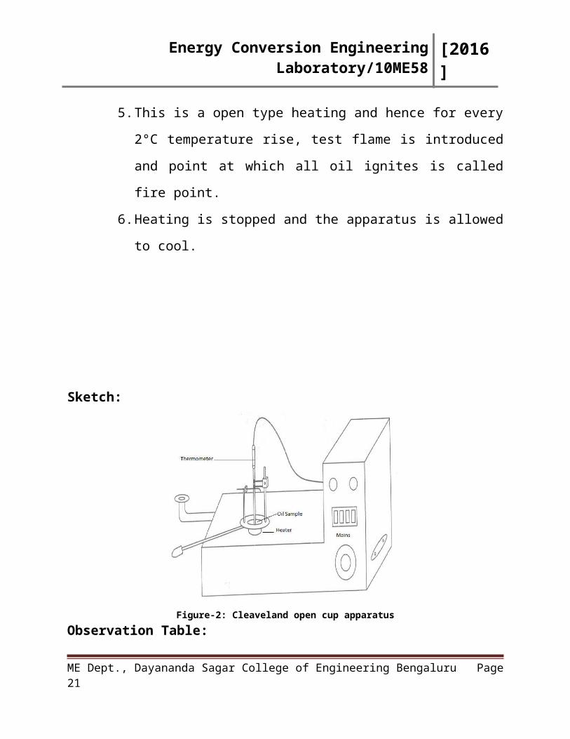
CLEAVELAND (OPEN CUP) FLASH & FIRE POINT APPARATUS
Aim: To determine the flash and fire points of diesel oil.
Apparatus Required:1. Cleaveland Open Cup apparatus, 2. Sample Oil, 3. Thermometer.
Procedure:1. Oil cup is cleaned and then diesel oil is poured into it up to the filling
mark,
2. The oil under test is heated and heating process is accompanied with
continuous stirring which ensures uniform distribution of heat,
3. The test flame is introduced for 5°C rise in temperature. No stirring is
done during the checking of test flame,
4. If a distinct flash is visible in the two observation parts, record the
temperature .This corresponds to flash point,
5. This is a open type heating and hence for every 2°C temperature rise,
test flame is introduced and point at which all oil ignites is called fire
point.
6. Heating is stopped and the apparatus is allowed to cool.
ME Dept., Dayananda Sagar College of Engineering Bengaluru Page 13
Energy Conversion Engineering Laboratory/10ME58 [2016]
Sketch:
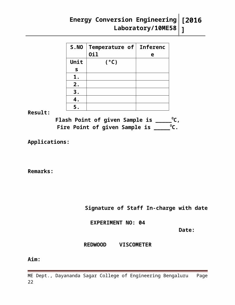
Figure-2: Cleaveland open cup apparatusObservation Table:
Result:Flash Point of given Sample is _____OC,Fire Point of given Sample is _____OC.
Applications:
Remarks:
Signature of Staff In-charge with date
ME Dept., Dayananda Sagar College of Engineering Bengaluru Page 14
S.NO Temperature of Oil InferenceUnits (°C)
1.2.3.4.5.

Energy Conversion Engineering Laboratory/10ME58 [2016]
EXPERIMENT NO: 04Date:
REDWOOD VISCOMETER
Aim:To determine the viscosity of the given specimen oil (Diesel Oil) at different temperatures.
Apparatus Required:1. Redwood Viscometer,
2. Thermometer,
3. Collecting Flask (50 ml),
4. Stop Clock,
5. Diesel oil.
PROCEDURE:
1. The weight balance is set to zero reading,
2. The specimen oil is poured into the flask and its initial temperature is found
out, also the mass of the flask with the oil is noted down,
3. Time taken by the specimen oil to fill 50ml flask is noted down. During the
flow the stop wire is lifted up,
4. Set the voltage to 150V and start reading the heated oil. Note down the time
taken to collect 50ml of oil for every 10°C rise in temperature. Also weigh
the flask with oil,
5. Then determine kinematic, dynamic viscosity and redwood number.
ME Dept., Dayananda Sagar College of Engineering Bengaluru Page 15
Energy Conversion Engineering Laboratory/10ME58 [2016]
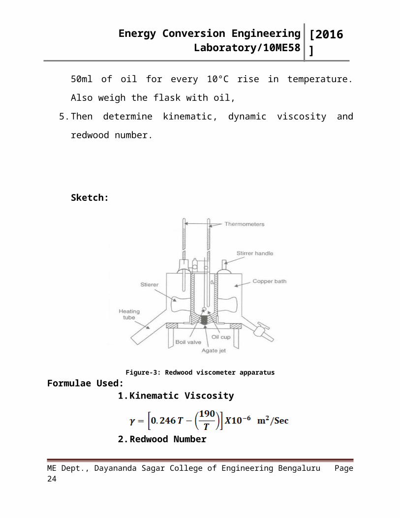
Sketch:
Figure-3: Redwood viscometer apparatusFormulae Used:
1. Kinematic Viscosity
2. Redwood Number
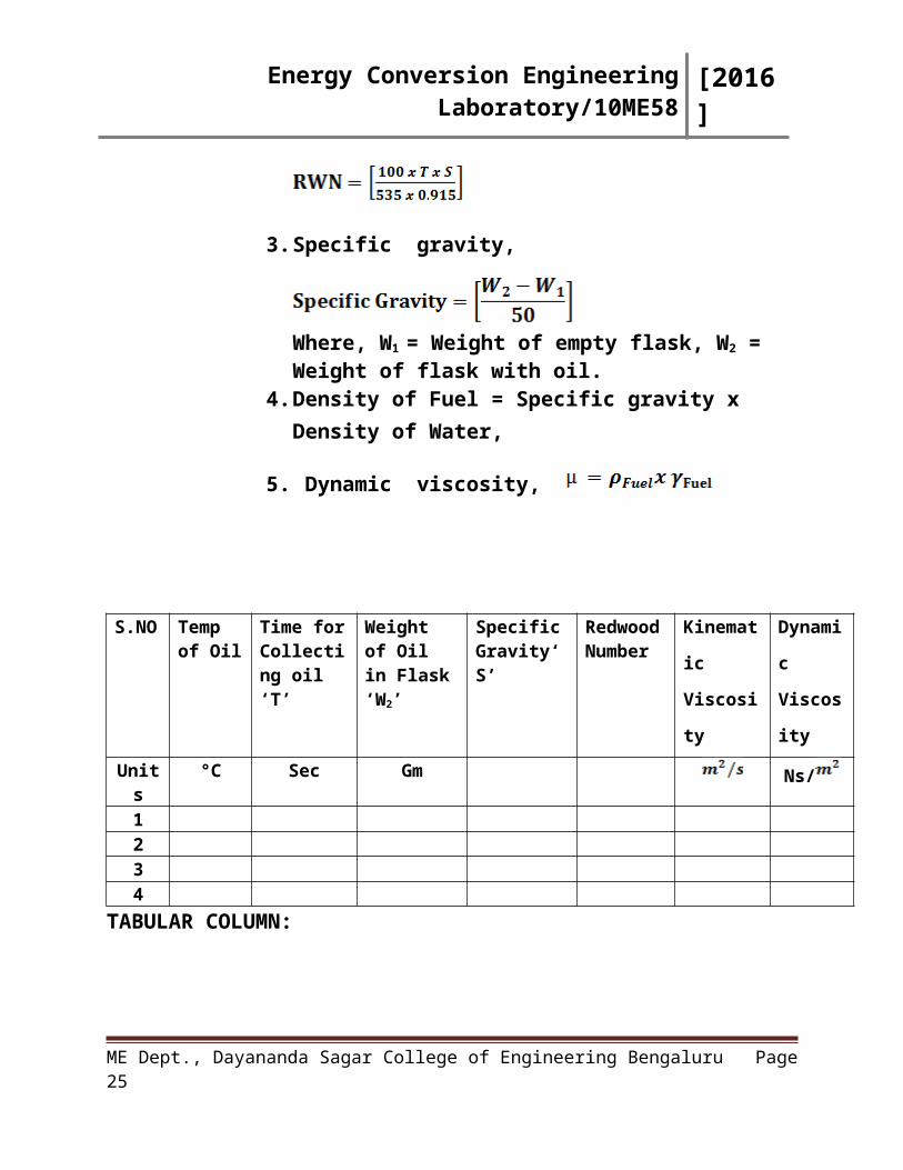
3. Specific gravity,
Where, W1 = Weight of empty flask, W2 = Weight of flask with oil.
4. Density of Fuel = Specific gravity x Density of Water,
5. Dynamic viscosity,
ME Dept., Dayananda Sagar College of Engineering Bengaluru Page 16
Energy Conversion Engineering Laboratory/10ME58 [2016]
S.NO Temp of Oil
Time for Collecting oil ‘T’
Weight of Oil in Flask ‘W2’
Specific Gravity‘S’
Redwood Number
Kinematic
Viscosity
Dynamic
Viscosity
Units °C Sec Gm Ns/
1234
TABULAR COLUMN:
GRAPHS:
1. Kinematic Viscosity vs Temperature,
2. Dynamic viscosity vs Temperature.
. RESULT: The Kinematic Viscosity and Dynamic Viscosity of the given
Specimen oil are determined.
Applications:
Remarks:
Signature of Staff In-charge with date
ME Dept., Dayananda Sagar College of Engineering Bengaluru Page 17
Energy Conversion Engineering Laboratory/10ME58 [2016]
EXPERIMENT NO: 05Date:
SAYBOLT VISCOMETER
Aim: To determine the viscosity of the given specimen oil (Lubricating Oil) at different temperatures.
Apparatus Required:1. Saybolt Viscometer,
2. Thermometer,
3. Collecting Flask (60 ml),
4. Stop Clock,
5. Lubricating Oil.
PROCEDURE:
1. The balance is set to zero reading. Weigh the empty flask and note down
the weight (W1).
2. The specimen oil is poured into the container and its initial temperature is
found out, also the voltage in the regulator is set to 230V.
3. Now the stop wire is lifted up and the time taken by the oil to fill 60 cc of
the flask is noted and then it is weighed (W2).
4. Now start heating the oil in the container.
5. For every 10 degree rise in temperature, find out the time taken by the oil
to fill 60 cc of the flask and then weigh the flask with oil (W2).
6. Tabulate the readings and find out kinematic and dynamic viscosity using
the formulae.
ME Dept., Dayananda Sagar College of Engineering Bengaluru Page 18

Energy Conversion Engineering Laboratory/10ME58 [2016]
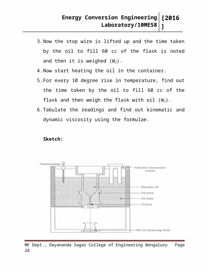
Sketch:
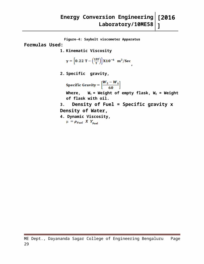
Figure-4: Saybolt viscometer ApparatusFormulas Used:
1. Kinematic Viscosity
,
2. Specific gravity,
Where, W1 = Weight of empty flask, W2 = Weight of flask with oil.
3. Density of Fuel = Specific gravity x Density of Water, 4. Dynamic Viscosity,
ME Dept., Dayananda Sagar College of Engineering Bengaluru Page 19
Energy Conversion Engineering Laboratory/10ME58 [2016]
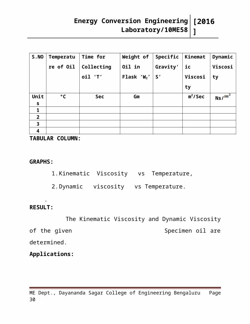
S.NO Temperature
of Oil
Time for
Collecting oil ‘T’
Weight of Oil
in Flask ‘W2’
Specific
Gravity‘S’
Kinematic
Viscosity
Dynamic
Viscosity
Units °C Sec Gm m2/Sec Ns/
1234
TABULAR COLUMN:
GRAPHS:
1. Kinematic Viscosity vs Temperature,
2. Dynamic viscosity vs Temperature.
. RESULT:
The Kinematic Viscosity and Dynamic Viscosity of the given
Specimen oil are determined.
Applications:
Remarks:
Signature of Staff In-charge with date
ME Dept., Dayananda Sagar College of Engineering Bengaluru Page 20
Energy Conversion Engineering Laboratory/10ME58 [2016]
EXPERIMENT NO: 06DATE:
TORSION VISCOMETERAim:
To determine the viscosity of the given specimen oil (SAE-40) at different temperatures.
Apparatus Required:1. Torsion Viscometer,
2. Thermometer,
3. Stop Clock,
4. Lubricating Oil.
PROCEDURE:1. The oil SAE-40 is filled in the oil cup so that the cylinder at the end of
the side gets completely immersed inside the oil. It is then placed on the
stand. The initial temperature of the oil is noted down.
2. The indent on the side of the circular disk is made to coincide with the
needle point using the rotating rod.
3. Now the torsion disk is rotated by 3600 and then to rotate freely. Then the
degree (angle) at the mark coincides and stops, then it reverses its
direction.
4. The value of Redwood seconds (t) is noted down from the chart provided
for the given angle.
5. The experiment is repeated for every 10°C rise in temperature of the oil.
6. Kinematic viscosity is then calculated using the formulae.
ME Dept., Dayananda Sagar College of Engineering Bengaluru Page 21
Energy Conversion Engineering Laboratory/10ME58 [2016]
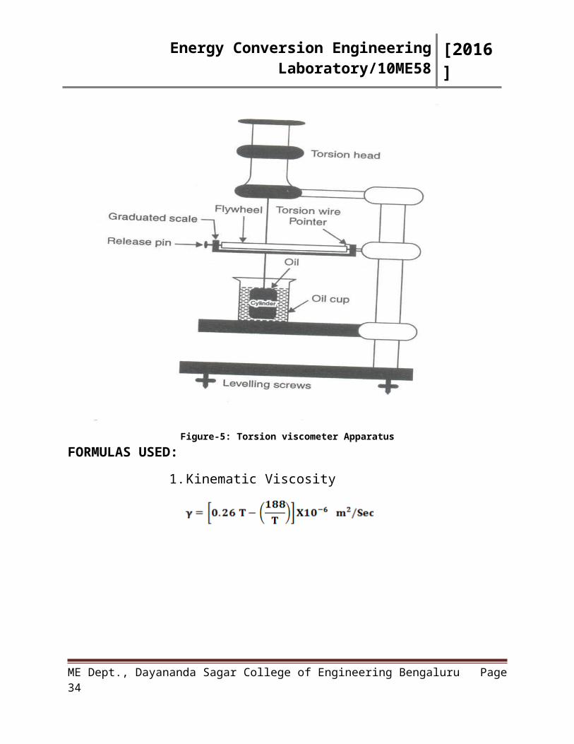
Sketch:
Figure-5: Torsion viscometer ApparatusFORMULAS USED:
1. Kinematic Viscosity
ME Dept., Dayananda Sagar College of Engineering Bengaluru Page 22
Energy Conversion Engineering Laboratory/10ME58 [2016]
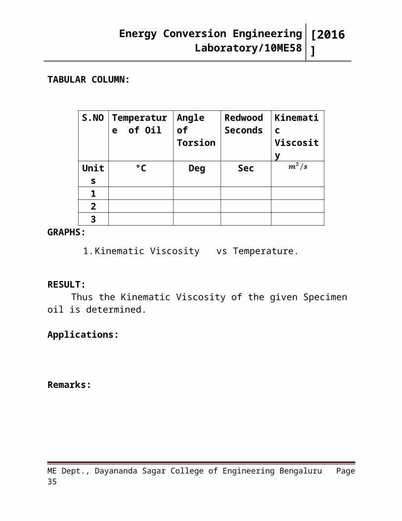
TABULAR COLUMN:
GRAPHS:
1. Kinematic Viscosity vs Temperature.
RESULT: Thus the Kinematic Viscosity of the given Specimen oil is determined.
Applications:
Remarks:
Signature of Staff In-charge with date
ME Dept., Dayananda Sagar College of Engineering Bengaluru Page 23
S.NO Temperature of Oil
Angle of Torsion
Redwood Seconds
Kinematic Viscosity
Units °C Deg Sec123
Energy Conversion Engineering Laboratory/10ME58 [2016]
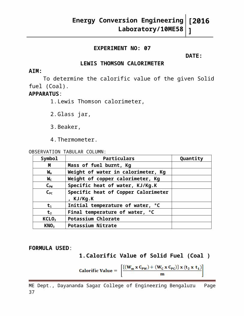
EXPERIMENT NO: 07DATE:
LEWIS THOMSON CALORIMETER AIM:
To determine the calorific value of the given Solid fuel (Coal).APPARATUS:
1. Lewis Thomson calorimeter,
2. Glass jar,
3. Beaker,
4. Thermometer.
OBSERVATION TABULAR COLUMN:Symbol Particulars Quantity
M Mass of fuel burnt, KgWm Weight of water in calorimeter, KgWC Weight of copper calorimeter, KgCPW Specific heat of water, KJ/Kg.K CPC Specific heat of Copper Calorimeter , KJ/Kg.K t1 Initial temperature of water, °Ct2 Final temperature of water, °C
KCLO3 Potassium ChlorateKNO3 Potassium Nitrate
FORMULA USED:1. Calorific Value of Solid Fuel (Coal )
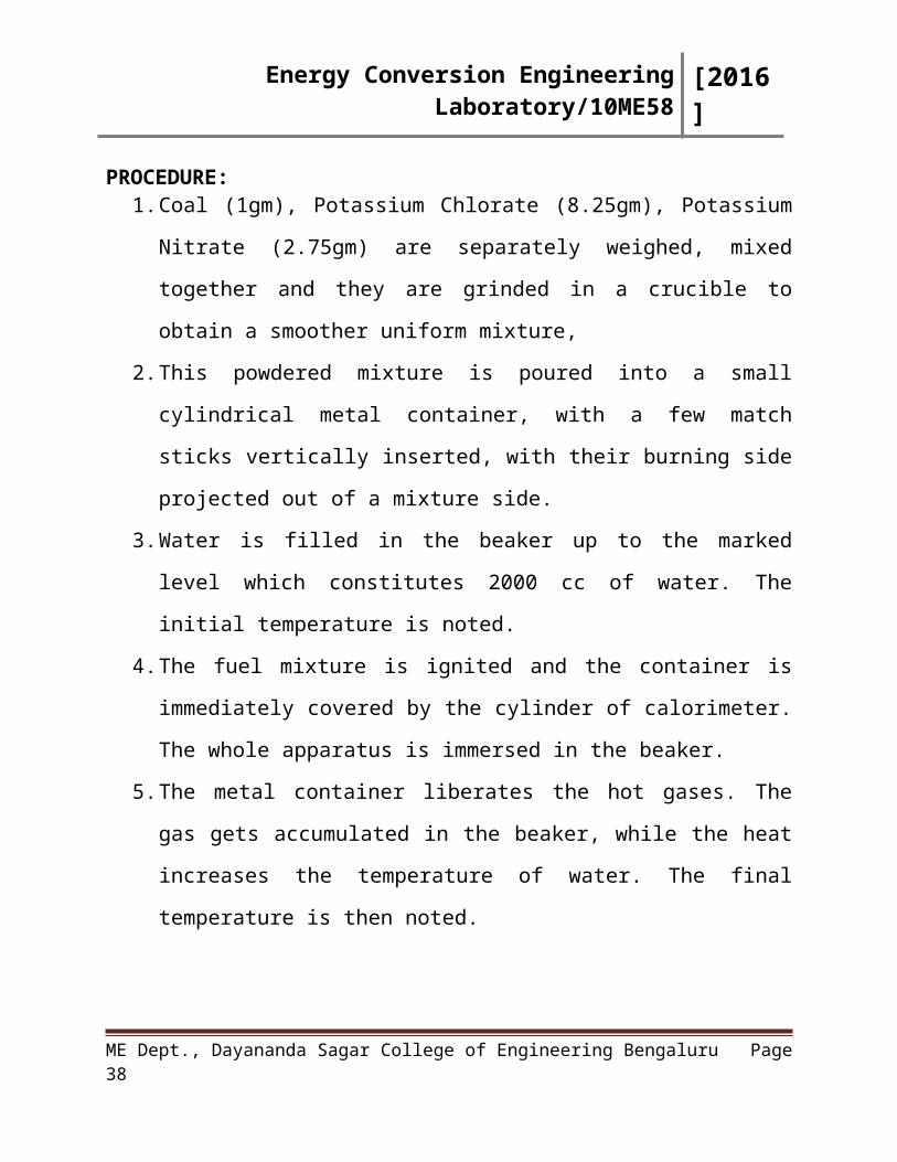
PROCEDURE:1. Coal (1gm), Potassium Chlorate (8.25gm), Potassium Nitrate (2.75gm) are
separately weighed, mixed together and they are grinded in a crucible to
obtain a smoother uniform mixture,
2. This powdered mixture is poured into a small cylindrical metal container,
with a few match sticks vertically inserted, with their burning side projected
out of a mixture side.
ME Dept., Dayananda Sagar College of Engineering Bengaluru Page 24
Energy Conversion Engineering Laboratory/10ME58 [2016]
3. Water is filled in the beaker up to the marked level which constitutes 2000
cc of water. The initial temperature is noted.
4. The fuel mixture is ignited and the container is immediately covered by the
cylinder of calorimeter. The whole apparatus is immersed in the beaker.
5. The metal container liberates the hot gases. The gas gets accumulated in the
beaker, while the heat increases the temperature of water. The final
temperature is then noted.
6. Heat liberated by coal = Heat absorbed by water. This is then used to
calculate the evaporative value of coal.
RESULT:
The calorific value of solid fuel (Coal) is _________________KJ/Kg
Applications:
Remarks:
Signature of Staff In-charge with date
ME Dept., Dayananda Sagar College of Engineering Bengaluru Page 25
Energy Conversion Engineering Laboratory/10ME58 [2016]
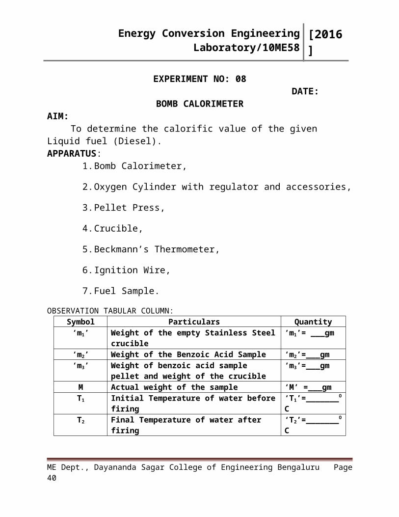
EXPERIMENT NO: 08DATE:
BOMB CALORIMETER AIM:
To determine the calorific value of the given Liquid fuel (Diesel).APPARATUS:
1. Bomb Calorimeter,
2. Oxygen Cylinder with regulator and accessories,
3. Pellet Press,
4. Crucible,
5. Beckmann’s Thermometer,
6. Ignition Wire,
7. Fuel Sample.
OBSERVATION TABULAR COLUMN:Symbol Particulars Quantity
‘m1’ Weight of the empty Stainless Steel crucible ‘m1’= ___gm‘m2’ Weight of the Benzoic Acid Sample ‘m2’=___gm‘m3’ Weight of benzoic acid sample pellet and weight
of the crucible‘m3’=___gm
M Actual weight of the sample ‘M’ =___gmT1 Initial Temperature of water before firing ‘T1’=_______OCT2 Final Temperature of water after firing ‘T2’=_______OC
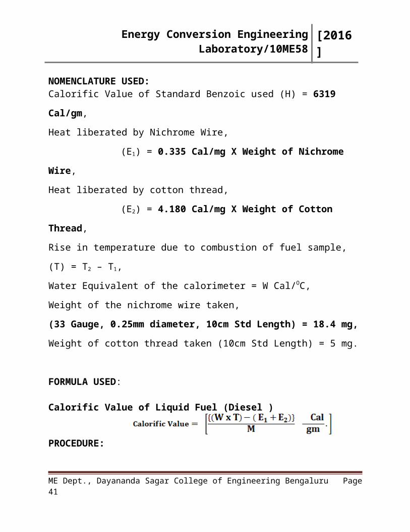
NOMENCLATURE USED:Calorific Value of Standard Benzoic used (H) = 6319 Cal/gm,
Heat liberated by Nichrome Wire,
(E1) = 0.335 Cal/mg X Weight of Nichrome Wire,
Heat liberated by cotton thread,
(E2) = 4.180 Cal/mg X Weight of Cotton Thread,
Rise in temperature due to combustion of fuel sample, (T) = T2 – T1,
Water Equivalent of the calorimeter = W Cal/OC,
ME Dept., Dayananda Sagar College of Engineering Bengaluru Page 26
Energy Conversion Engineering Laboratory/10ME58 [2016]
Weight of the nichrome wire taken,
(33 Gauge, 0.25mm diameter, 10cm Std Length) = 18.4 mg,
Weight of cotton thread taken (10cm Std Length) = 5 mg.
FORMULA USED:
Calorific Value of Liquid Fuel (Diesel )
PROCEDURE:1. About one gram of the fuel is weighed in the crucible; a piece of firing wire
is stretched between the electrodes in such a manner that it is in close
contact with the fuel so that it can be ignited,
2. Often solid fuel made in to pellets can also be determined for its calorific
value,
3. The cap is screwed down on the bomb and oxygen is filled in the cup to a
pressure of about 20atm. The bomb is then placed in a weighed amount of
water taken in the calorimeter,
4. Electrical connections are made, stirring is started and temperature reading is
taken with a thermometer reading to 0.01OC,
5. When the thermometer shows a steady temperature the fuel is made to fire
and temperature readings are continued for few minutes after the maximum
temperature is attained,
6. The water is stirred during the experiment,
7. The bomb is then removed and allowed to stand so that the acid mist may
settle down. The pressure is slowly released and the contents of the bomb
are carefully washed,
8. In actual practice correction needs to be made for the heat of fuse wire.
9. Heat liberated by Fuel = Heat absorbed by water.
ME Dept., Dayananda Sagar College of Engineering Bengaluru Page 27
Energy Conversion Engineering Laboratory/10ME58 [2016]
RESULT:
The calorific value of Liquid fuel (Diesel) is _________________Cal/gm.
Applications:
Remarks:
Signature of Staff In-charge with date
ME Dept., Dayananda Sagar College of Engineering Bengaluru Page 28
Energy Conversion Engineering Laboratory/10ME58 [2016]
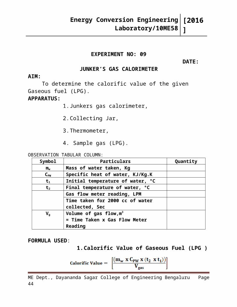
EXPERIMENT NO: 09 DATE:
JUNKER’S GAS CALORIMETERAIM:
To determine the calorific value of the given Gaseous fuel (LPG).APPARATUS:
1. Junkers gas calorimeter,
2. Collecting Jar,
3. Thermometer,
4. Sample gas (LPG).
OBSERVATION TABULAR COLUMN:Symbol Particulars Quantity
mw Mass of water taken, KgCPW Specific heat of water, KJ/Kg.K
t1 Initial temperature of water, °Ct2 Final temperature of water, °C
Gas flow meter reading, LPMTime taken for 2000 cc of water collected, Sec
Vg Volume of gas flow,m3 = Time Taken x Gas Flow Meter Reading
FORMULA USED:1. Calorific Value of Gaseous Fuel (LPG )
PROCEDURE:1. Ensure the continuous flow of water through the water jacket and pass the
measured volume of gas through the gas meter,
2. Adjust the pressure regulator for uniform flow of gas and record the
manometer reading,
3. Record the inlet gas temperature and cooling water temperature at the inlet,
ME Dept., Dayananda Sagar College of Engineering Bengaluru Page 29
Energy Conversion Engineering Laboratory/10ME58 [2016]
4. Ignite the gas using the burner ensuring complete combustion and record the
amount of gas taken to heat the 2000 cc of water,
5. Note down the final temperature of water.
RESULT:The calorific value of the Gaseous fuel (LPG) is_______________KJ/m3
Applications:
Remarks:
Signature of Staff In-charge with date
ME Dept., Dayananda Sagar College of Engineering Bengaluru Page 30
Energy Conversion Engineering Laboratory/10ME58 [2016]
EXPERIMENT NO: 10DATE:
VALVE TIMING DIAGRAM-FOUR STROKE CUT SECTION DIESEL ENGINE
AIM:To draw the valve timing diagram for a four stroke, cut section Diesel
Engine.APPARATUS:
1. Cut Section Model of a Four stroke Diesel Engine,
2. Paper Strips,
3. Torch Light,
4. Measuring Tape.
SPECIFICATIONS OF THE MODEL:Four Stroke Cut Section Diesel Engine Specification
Brake Power 3.7 KWSpeed 1500 rpmCompression Ratio 16:1Circumference of Fly Wheel 1240 mmDiameter of Fly Wheel, m 395 mm
PROCEDURE:1. Keep the de-compression lever in the vertical position,
2. Bring the TDC mark to the pointer level,
3. Rotate the flywheel till the Inlet Valve moves down (Inlet Valve Opens).
4. Draw a line on the flywheel in front of the pointer. Take the reading.
5. Continue to rotate the flywheel till the inlet valve goes down and comes to
the horizontal position. Take the reading.
6. Continue to rotate the flywheel till the Exhaust Valve Opens, take down the
reading.
7. Similarly flywheel is rotated until the Exhaust Valve closes. Tabulate the
readings and draw the actual valve timing diagram.
ME Dept., Dayananda Sagar College of Engineering Bengaluru Page 31
Energy Conversion Engineering Laboratory/10ME58 [2016]
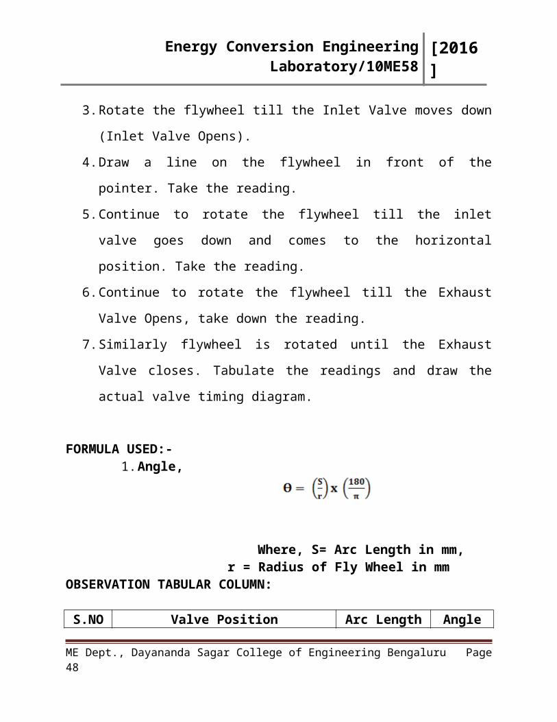
FORMULA USED:-1. Angle,
Where, S= Arc Length in mm, r = Radius of Fly Wheel in mm
OBSERVATION TABULAR COLUMN:
S.NO Valve Position Arc Length (S) Angle
Units Events-Valve Position cm mm Degrees1 Inlet Valve Opens -Before TDC2 Inlet Valve Closes -After BDC3 Exhaust Valve Opens -Before BDC4 Exhaust Valve Closes -After TDC
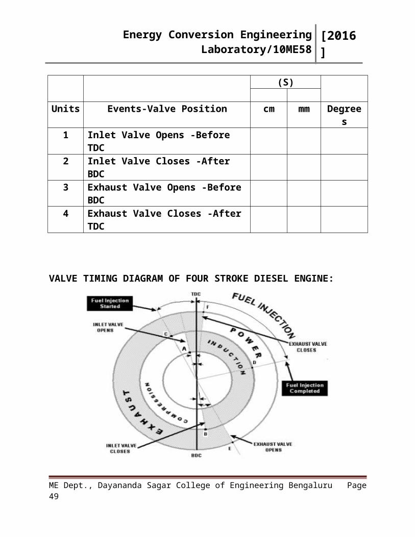
VALVE TIMING DIAGRAM OF FOUR STROKE DIESEL ENGINE:
Figure-6: Valve timing diagram-4 stroke diesel engine
ME Dept., Dayananda Sagar College of Engineering Bengaluru Page 32
Energy Conversion Engineering Laboratory/10ME58 [2016]
RESULT:Thus the actual valve timing diagram is drawn based on the angles obtained
from the four stroke, cut section diesel engine.
Applications:
Remarks:
Signature of Staff In-charge with date
ME Dept., Dayananda Sagar College of Engineering Bengaluru Page 33
Energy Conversion Engineering Laboratory/10ME58 [2016]
EXPERIMENT NO: 11DATE:
PORT TIMING DIAGRAM-TWO STROKE CUT SECTION PETROL ENGINE
AIM:To draw the port timing diagram for a two stroke, cut section petrol Engine.
APPARATUS:1. Cut Section Model of a Two Stroke Petrol Engine,
2. Paper Strips,
3. Torch light,
4. Measuring Tape.
OBSERVATION TABULAR COLUMN:Two Stroke Cut Section Petrol Engine
Make Bajaj ChetakNumber of Strokes TwoNumber of Ports 3 [Inlet Port, Transfer Port, Exhaust Port]Bore x Stroke 56.7 mm x 56.7mmSpeed 3,500 rpmCubic Capacity 145.45 CCFuel Used Petrol
PROCEDURE:1. Mark the TDC and BDC on the flywheel,
2. Rotate the flywheel provided,
3. Observe the position of the piston so that you know the port opening /
closing,
4. When the piston reaches the TDC position, the light provided at the TDC
begins to glow, which is an indication of piston reaching the TDC,
5. Measure the angle at which the port opens / closes with respect to TDC /
BDC with the help of circular protractor provided on the flywheel, so that
the angle is obtained directly,
6. With the angles available, draw the actual Port Timing diagram,
ME Dept., Dayananda Sagar College of Engineering Bengaluru Page 34
Energy Conversion Engineering Laboratory/10ME58 [2016]
7. This Port Timing Diagram can be drawn for Ports in Just Open Position and
for ports in Fully Opened Position.
TABULAR COLUMN:
S.NO Port Position Reference to Dead Centers
Angle
Units Events-Port Position Before/After Degrees
1. Exhaust Port Opens (EPO) After TDCBefore BDC
2. Transfer Port Opens(TPO) After TDCBefore BDC
3. Transfer Port Closes(TPC) Before TDCAfter BDC
4. Exhaust Port Closes (EPC) Before TDCAfter BDC
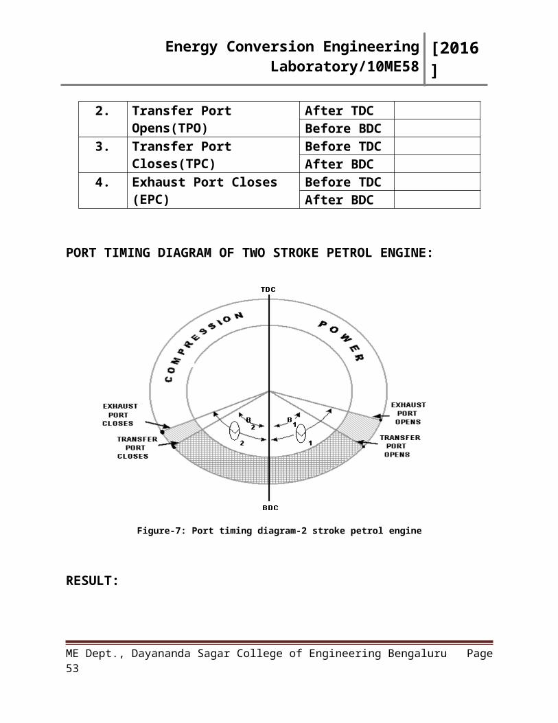
PORT TIMING DIAGRAM OF TWO STROKE PETROL ENGINE:
Figure-7: Port timing diagram-2 stroke petrol engine
ME Dept., Dayananda Sagar College of Engineering Bengaluru Page 35
Energy Conversion Engineering Laboratory/10ME58 [2016]
RESULT:Thus the actual port timing diagram is drawn based on the angles obtained
from the Two stroke, Cut section Petrol Engine.
Applications:
Remarks:
Signature of Staff In-charge with date
ME Dept., Dayananda Sagar College of Engineering Bengaluru Page 36
Energy Conversion Engineering Laboratory/10ME58 [2016]
EXPERIMENT NO: 12DATE:
PLANIMETERAIM:
To determine the area of irregular figure by using Planimeter.APPARATUS:
1. Planimeter,
2. White Sheet,
3. Regular Surface (Drawing Board).
PROCEDURE:1. Fix the figure whose area is to be determined on a smooth surface,
preferably on a drawing board,2. Choose the proportion to be 1:100 as the scale ratio. Now the tracer is set to
12:11 using vernier scale,3. To start with the lever is kept 90 degrees to the tracer scale and is fixed on
the table,4. Initial values on the scale may be set to zero or can be taken as it is,5. Using the tracer point the lever is moved on irregular surface to trace the
area in clockwise direction and then it is brought back to initial position,6. The final reading is noted down and the difference between the two readings
is multiplied by the proportion chosen to get the area,
7. The percentage error of planimeter is then calculated using the formula given.
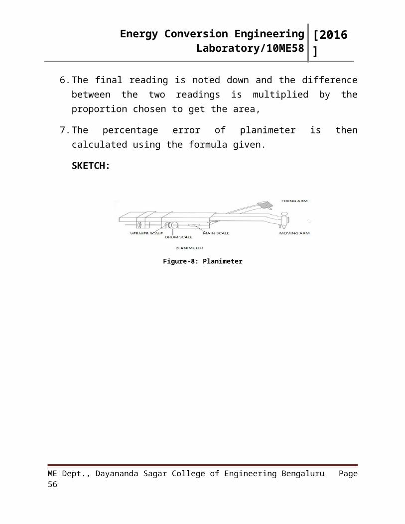
SKETCH:
Figure-8: Planimeter
ME Dept., Dayananda Sagar College of Engineering Bengaluru Page 37
Energy Conversion Engineering Laboratory/10ME58 [2016]
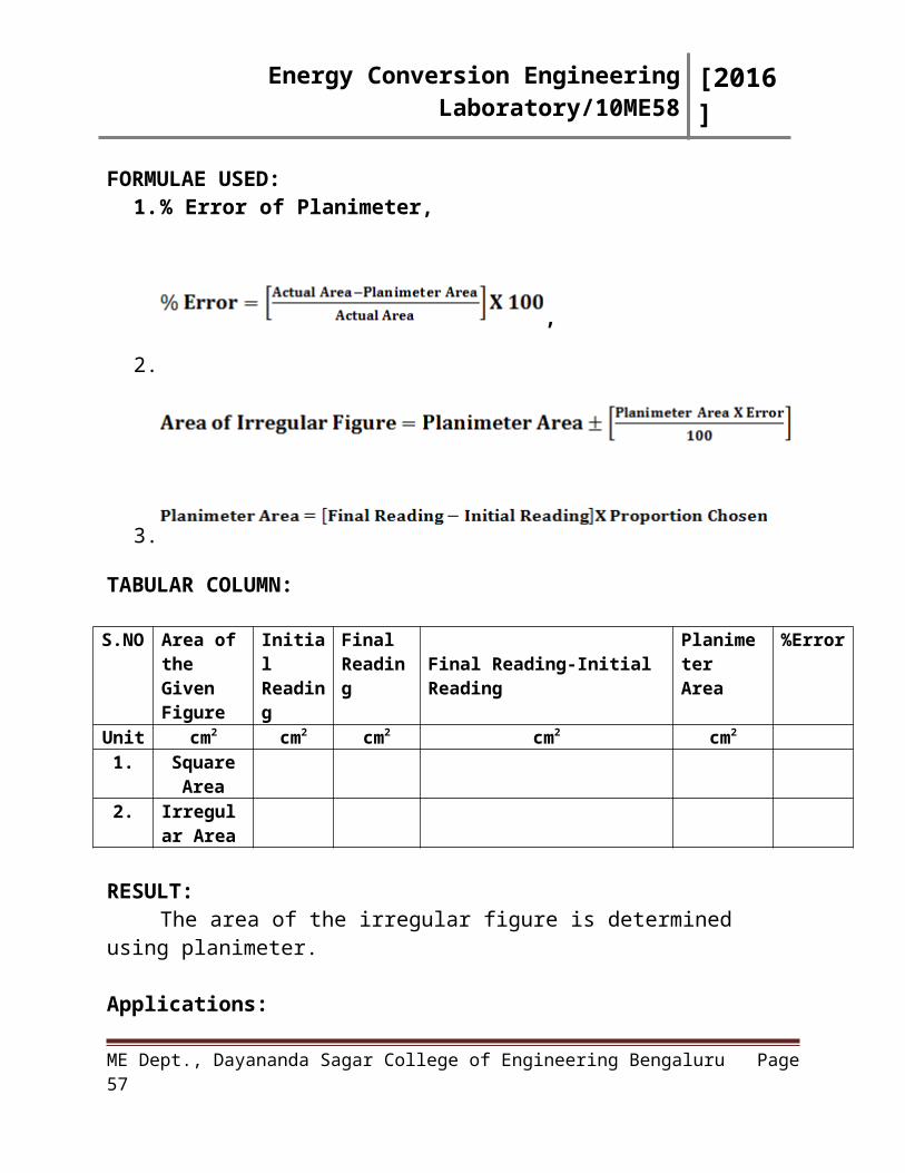
FORMULAE USED:1. % Error of Planimeter,
,
2.
3.
TABULAR COLUMN:
S.NO Area of the Given Figure
Initial Reading
Final Reading Final Reading-Initial Reading
Planimeter Area
%Error
Unit cm2 cm2 cm2 cm2 cm2
1. Square Area
2. Irregular Area
RESULT:The area of the irregular figure is determined using planimeter.
Applications:
Remarks:
Signature of Staff In-charge with date
ME Dept., Dayananda Sagar College of Engineering Bengaluru Page 38
Energy Conversion Engineering Laboratory/10ME58 [2016]
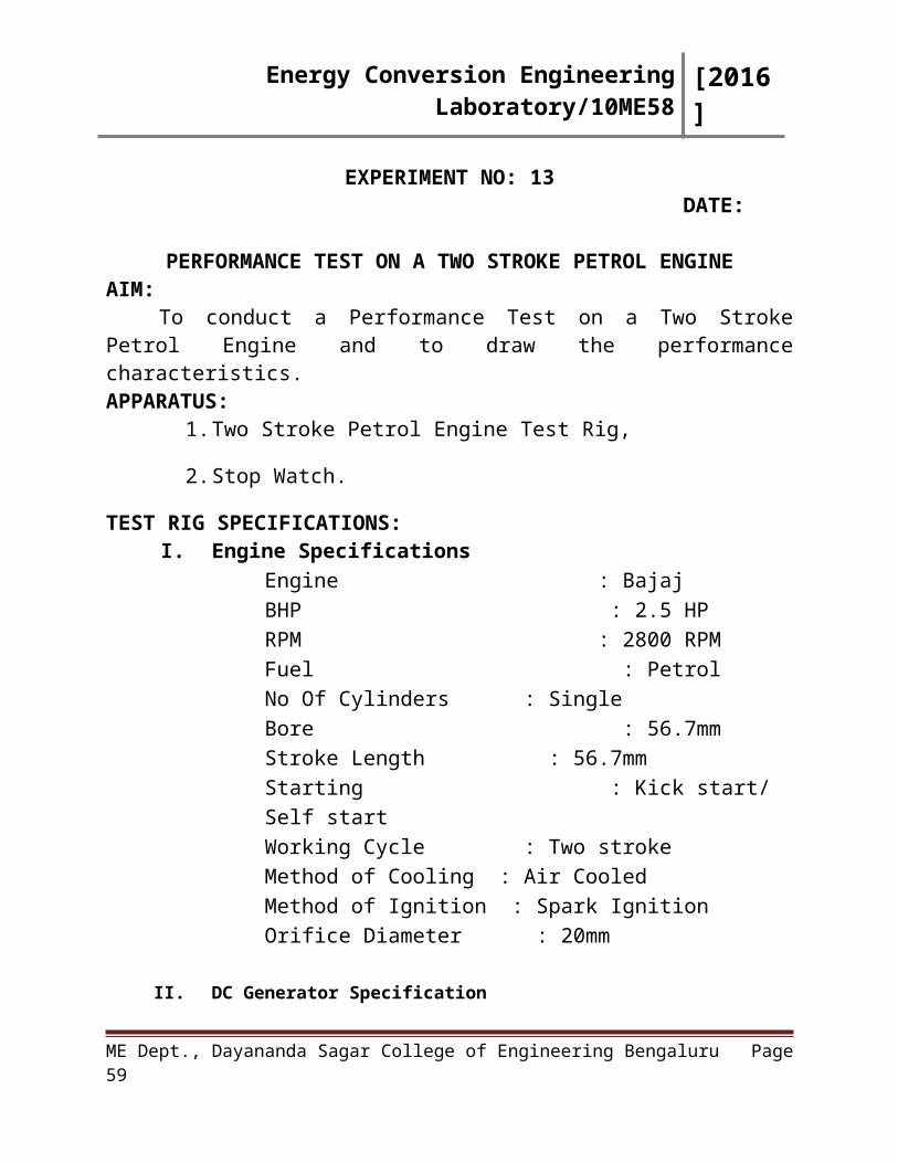
EXPERIMENT NO: 13 DATE:
PERFORMANCE TEST ON A TWO STROKE PETROL ENGINEAIM:
To conduct a Performance Test on a Two Stroke Petrol Engine and to draw the performance characteristics.APPARATUS:
1. Two Stroke Petrol Engine Test Rig,
2. Stop Watch.
TEST RIG SPECIFICATIONS:I. Engine Specifications
Engine : BajajBHP : 2.5 HPRPM : 2800 RPMFuel : PetrolNo Of Cylinders : SingleBore : 56.7mmStroke Length : 56.7mmStarting : Kick start/ Self startWorking Cycle : Two strokeMethod of Cooling : Air CooledMethod of Ignition : Spark IgnitionOrifice Diameter : 20mm
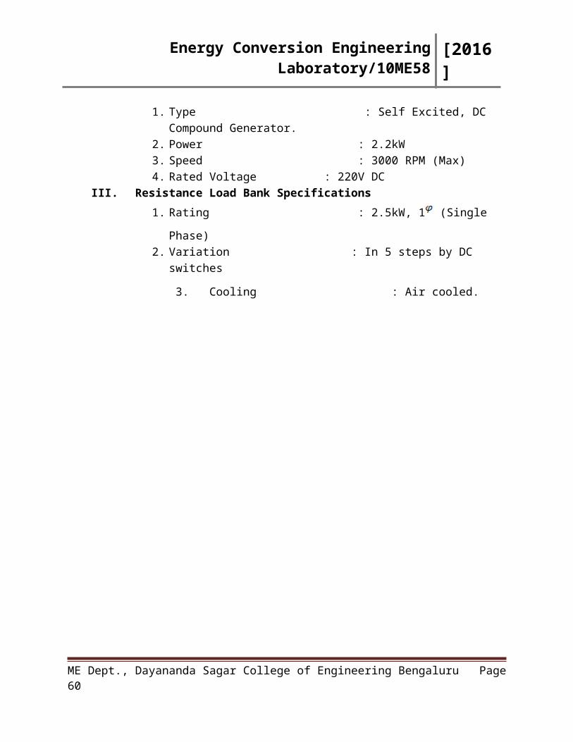
II. DC Generator Specification1. Type : Self Excited, DC Compound Generator.2. Power : 2.2kW3. Speed : 3000 RPM (Max)4. Rated Voltage : 220V DC
III. Resistance Load Bank Specifications
1. Rating : 2.5kW, 1 (Single Phase)
2. Variation : In 5 steps by DC switches
3. Cooling : Air cooled.
ME Dept., Dayananda Sagar College of Engineering Bengaluru Page 39
Energy Conversion Engineering Laboratory/10ME58 [2016]
PROCEDURE: 1.) Connect the instrumentation power input plug to a 230V, 50 Hz AC single phase AC
supply. Now all the digital meters namely, RPM indicator, temperature indicator
display the respective readings,
2.) Fill up the petrol to the fuel tank mounted behind the panel,
3.) Start the engine with the help of kicker provided at the rear end of the engine,
4.) Allow the engine to stabilize the speed i.e. 2800 RPM by adjusting the accelerator
knob,
5.) Apply ¼ loads up to 2kW (500W – 2kW),
6.) Note down all the required parameters mentioned below
a) Speed of the engine in RPM.
b) Load from ammeter in amps.
c) Burette reading in cc.
d) Manometer reading in mm.
e) Time taken for consumption of Xcc petrol in seconds.
f) Exhaust gas temperature in 0C.
7.) Load the engine step by step with the use of DC switches provided on the load bank
panel.
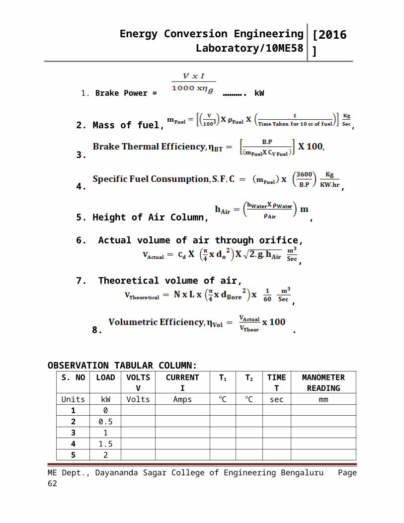
FORMULAE USED:
1. Brake Power = ………. kW
2. Mass of fuel, ,
3.
4. ,
5. Height of Air Column, ,
ME Dept., Dayananda Sagar College of Engineering Bengaluru Page 40
Energy Conversion Engineering Laboratory/10ME58 [2016]
6. Actual volume of air through orifice,
,
7. Theoretical volume of air,
,
8. .
OBSERVATION TABULAR COLUMN:S. NO LOAD VOLTS
VCURRENT
IT1 T2 TIME
TMANOMETER
READINGUnits kW Volts Amps oC oC sec mm
1 02 0.53 14 1.55 2
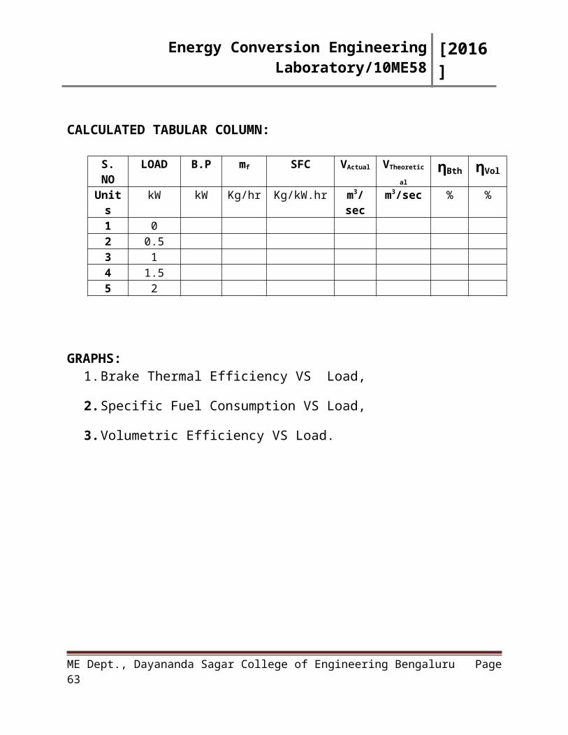
CALCULATED TABULAR COLUMN:
S. NO LOAD B.P mf SFC VActual VTheoretical ηBth ηVol
Units kW kW Kg/hr Kg/kW.hr m3/sec m3/sec % %1 02 0.53 14 1.55 2
GRAPHS: 1. Brake Thermal Efficiency VS Load,
2. Specific Fuel Consumption VS Load,
3. Volumetric Efficiency VS Load.
ME Dept., Dayananda Sagar College of Engineering Bengaluru Page 41
Energy Conversion Engineering Laboratory/10ME58 [2016]
RESULT: Thus the performance test on a Two Stroke Petrol engine is conducted under different loading conditions, readings tabulated and the characteristics curves are drawn.
Applications:
Remarks:
Signature of Staff In-charge with date
ME Dept., Dayananda Sagar College of Engineering Bengaluru Page 42
Energy Conversion Engineering Laboratory/10ME58 [2016]
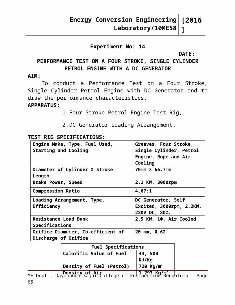
Experiment No: 14DATE:
PERFORMANCE TEST ON A FOUR STROKE, SINGLE CYLINDER PETROL ENGINE WITH A DC GENERATOR
AIM:To conduct a Performance Test on a Four Stroke, Single Cylinder Petrol
Engine with DC Generator and to draw the performance characteristics.APPARATUS:
1. Four Stroke Petrol Engine Test Rig,
2. DC Generator Loading Arrangement.
TEST RIG SPECIFICATIONS:Engine Make, Type, Fuel Used, Starting and Cooling
Greaves, Four Stroke, Single Cylinder, Petrol Engine, Rope and Air Cooling
Diameter of Cylinder X Stroke Length 70mm X 66.7mmBrake Power, Speed 2.2 KW, 3000rpm
Compression Ratio 4.67:1
Loading Arrangement, Type, Efficiency DC Generator, Self Excited, 3000rpm, 2.2KW, 220V DC, 80%.
Resistance Load Bank Specifications 2.5 KW, 1Φ, Air Cooled
Orifice Diameter, Co-efficient of Discharge of Orifice
20 mm, 0.62
PROCEDURE:1) Connect the instrumentation power input plug to a 230v, 50 Hz AC single
phase AC supply. Now all the digital meters namely, RPM indicator,
temperature indicator display the respective readings,
2) Fill up the petrol to the fuel tank mounted behind the panel,
3) Check the lubricating oil level in the oil sump with the dipstick provided,
4) Start the engine with the help of self-starter arrangement OR with rope and
pulley arrangement,
ME Dept., Dayananda Sagar College of Engineering Bengaluru Page 43
Fuel SpecificationsCalorific Value of Fuel 43, 500 KJ/KgDensity of Fuel (Petrol) 720 Kg/m3
Density of Air 1.293 Kg/m3
Energy Conversion Engineering Laboratory/10ME58 [2016]
5) Allow the engine to stabilize the speed i.e., 3000 RPM by adjusting the
accelerator knob provided on the table,
6) Apply ¼ load (500W heater),
7) Note down all the required parameters such as Speed of the engine, Load
from ammeter, Manometer reading, Time taken for consumption of fuel,
Temperatures at various points,
8) Load the engine step by step with the use of DC switches provided on the
load bank such as,
(i.). 1/2 load (1000W),
(ii.). 3/4 load (1500W),
(iii.).Full load (2000W),
(iv.) 20% overload (2500W).
FORMULAE USED:
1. ,
2. Mass of fuel, ,
3. ,
4. Height of Air Column, ,
5. Actual volume of air, ,
6. Swept Volume of air, ,
ME Dept., Dayananda Sagar College of Engineering Bengaluru Page 44
Energy Conversion Engineering Laboratory/10ME58 [2016]
7.
8. ,
ME Dept., Dayananda Sagar College of Engineering Bengaluru Page 45
Energy Conversion Engineering Laboratory/10ME58 [2016]
NOMENCLATURE: V = DC Voltage in volts,
I = DC Current in Amps,
η GENE = Generator Efficiency,
T1 = Ambient Temperature OC,
T2 = Exhaust gas outlet from the engine OC.
OBSERVATION TABULAR COLUMN:
OPERATING CONDITIONS EMPLOYED:
CALCULATED RESULTS:
S.NO Brake Power
Brake Thermal
Efficiency
Specific Fuel Consumption
Actual Volume
Swept Volume
Volumetric Efficiency
Units KW % Kg/KW.hr m3/sec m3/sec %1.2.3.4.5.
GRAPHS: 1.) Brake Thermal Efficiency VS BP in KW,2.) Specific Fuel Consumption VS BP in KW,
ME Dept., Dayananda Sagar College of Engineering Bengaluru Page 46
S.NO Load Voltage Current Speed Height of
H2O
Column
Time for 10
CC of Fuel
Consumption
T1 T2
Units KW Volts Amps RPM ‘mm’ Sec 0C 0C
1.
2.
3.
4.
5.
Energy Conversion Engineering Laboratory/10ME58 [2016]
RESULT:Thus the performance test on a four stroke, single cylinder petrol engine is conducted under different loading conditions, readings are tabulated, calculations are done and the characteristics curves are drawn.
Applications:
Remarks:
Signature of Staff In-charge with date
ME Dept., Dayananda Sagar College of Engineering Bengaluru Page 47
Energy Conversion Engineering Laboratory/10ME58 [2016]
Experiment No: 15DATE:
PERFORMANCE TEST AND HEAT BALANCE CALCULATIONS ON A FOUR STROKE, SINGLE CYLINDER DIESEL ENGINE WITH
MECHANICAL ROPE BRAKE LOADING ARRANGEMENT AIM:
To conduct a Performance Test and Heat Balance Calculations on a Four Stroke, single Cylinder Diesel Engine with mechanical rope brake loading arrangement and to draw the performance characteristics.
APPARATUS:1. Four Stroke Diesel Engine Test Rig,
2. Mechanical Loading Arrangement.
TEST RIG SPECIFICATIONS:
Engine Make, Type and Fuel Used Kirloskar, Four Stroke, Single Cylinder, Diesel Engine
Method of Cooling Water CooledDiameter of Cylinder X Stroke Length 80 mm X 110 mm
Brake Power 3.7 KW
Speed 1500 rpm
Brake Drum Diameter (Mechanical Loading Setup)
280 mm
Diameter of Rope 15 mm
Compression Ratio 16:1
Circumference of Fly Wheel 1240 mm
Orifice Diameter, Co-efficient of Discharge of Orifice
20 mm, 0.62
PROCEDURE:1. Keep the de-compression valve in the vertical position and start
rotating the flywheel,
ME Dept., Dayananda Sagar College of Engineering Bengaluru Page 48
Fuel SpecificationsCalorific Value of Fuel 42,500 KJ/KgDensity of Fuel (Diesel) 840 Kg/m3
Density of Air 1.293 Kg/m3
Energy Conversion Engineering Laboratory/10ME58 [2016]
2. Bring the valve to the horizontal position, after 3 to 4 rotations, start
the engine,
3. Open the brake drum coolant valve,
4. Attach the weight to the weight hanger of brake drum and note down
the spring balance reading,
5. Note the inlet and outlet temperature of the cooling water along with
the manometric readings,
6. Note down the time taken for 10 CC fuel consumption using stop
watch,
7. Measure the speed of the engine using tachometer,
8. Repeat the procedure with different weights and tabulate the readings.
CALCULATION OF FRICTION POWER:Friction Power of a Single Cylinder Diesel engine can be calculated by
many methods. Willian’s Line method is the one which is commonly used for
determination of FP. In this method, BP (KW) is plotted along the positive ‘x’ axis
and Mass of fuel consumed (Kg/Sec) is plotted along ‘y’ axis. The extrapolation of
fuel consumed to negative ‘x’ axis denotes the measure of FP (KW) of the engine.
FORMULAE USED:
1. ,
2. Heat Equivalent to BP, ,
3. Mass of fuel, ,
4. ,
ME Dept., Dayananda Sagar College of Engineering Bengaluru Page 49
Energy Conversion Engineering Laboratory/10ME58 [2016]
5.
6.
7. ,
8. Height of Air Column, ,
9. Actual volume of air through orifice,
,
10. Swept Volume of air,
,
11. ,
12.
NOMENCLATURE: N = Speed rpm, D = Diameter of Brake drum (330mm),
d = Diameter of Rope m, W = Weights added Kg,
S = Spring Balance Reading N,
T1 = Inlet water temperature of engine jacket,
T2= Outlet water temperature of engine jacket,
T3 = Outlet water temperature from calorimeter,
ME Dept., Dayananda Sagar College of Engineering Bengaluru Page 50
Energy Conversion Engineering Laboratory/10ME58 [2016]
T4 = Exhaust gas temperature from the engine,
T5 = Exhaust gas temperature from calorimeter.
FORMULAE FOR HEAT BALANCE CALCULATIONS:
1. Heat Input,
2. Heat Loss to Cooling Water,
3. Heat Loss from Exhaust Gases = Heat gained by Calorimeter Water,
Heat Loss from Exhaust Gases
4. Heat Unaccounted ,
OBSERVATION TABULAR COLUMN:
ME Dept., Dayananda Sagar College of Engineering Bengaluru Page 51
Energy Conversion Engineering Laboratory/10ME58 [2016]
S.NO Load Speed Height of
H2O
Column
Time for 10
CC of Fuel
Consumption
T1 T2 T3 T4 T5 Volume of Water
Circulated
W S Engine Calorimeter
Units Kg Kg RPM ‘mm’ Sec 0C 0C 0C 0C 0C CC/sec CC/sec
1.
2.
3.
4.
5.
CALCULATED RESULTS:
S.NO Torque mfuel BP FP[Willian’s Line]
IP ηBTH ηMECH SFC Actual Volume
Swept Volume
ηVOL
Units Nm Kg/Sec KW KW KW % % Kg/KW.hr m3/sec m3/sec %1.2.3.4.
HEAT BALANCE TABULATIONS:
HEAT BALANCE SHEET in kJ/minOPERATING CONDITION EMPLOYED =
SL. NO. PARTICULARS INPUT % OUTPUT %
UNITS VARIOUS PARTICULARS kJ/min % kJ/min %
1 HEAT INPUT2 HEAT EQUIVALENT TO BP3 HEAT LOSS TO WATER 4 HEAT LOSS TO EXHAUST 5 HEAT UNACCOUNTED6 TOTAL
GRAPHS: 1.) Brake Thermal Efficiency, Indicated Thermal Efficiency, Mechanical
Efficiency, SFC VS BP in KW,
2.) Willian’s Line Plot.
RESULT:Thus the performance test and heat balance calculations on a four stroke diesel engine is conducted under different loading conditions, readings tabulated and the characteristics curves are drawn.
ME Dept., Dayananda Sagar College of Engineering Bengaluru Page 52
Energy Conversion Engineering Laboratory/10ME58 [2016]
Applications:
Remarks:
Signature of Staff In-charge with date
ME Dept., Dayananda Sagar College of Engineering Bengaluru Page 53
Energy Conversion Engineering Laboratory/10ME58 [2016]
Experiment No: 16DATE:
PERFORMANCE TEST ON A VARIABLE COMPRESSION RATIO MULTI FUEL ENGINE
AIM:To conduct a Performance Test and Heat Balance Calculations on a Variable
Compression Ratio, Four Stroke, Single Cylinder Multi-Fuel Engine Coupled to an Eddy Current Dynamometer.APPARATUS:
1. Four Stroke, Single Cylinder Multi fuel Engine Test Rig,
2. Mechanical Loading Arrangement.
TEST RIG SPECIFICATIONS:Engine Make, Type and Fuel Used Kirloskar, Four Stroke, Single
Cylinder, Diesel & Petrol EngineMethod of Cooling Water CooledDiameter of Cylinder X Stroke Length 80 mm X 110 mm
Brake Power 3.7 KW
Speed 1500 rpm
Compression Ratio for CI Engine 12 to 16
Compression Ratio for SI Engine 6 to 10
Calorific Value of Diesel, Density of Diesel 42,500 KJ/Kg, 840 Kg/m3
Calorific Value of Petrol, Density of Petrol 43,500 KJ/Kg, 720 Kg/m3
Orifice Diameter, Co-efficient of Discharge of Orifice
20 mm, 0.62
PROCEDURE:1) Fill up the required quantity of Diesel/Petrol to the fuel tank kept
behind the panel,
2) Plug the mains cord and Switch ON the control panel so that all the
Indicators will display their respective readings,
ME Dept., Dayananda Sagar College of Engineering Bengaluru Page 54
Energy Conversion Engineering Laboratory/10ME58 [2016]
3) Allow sufficient quantity of soft water to the Exhaust gas calorimeter
and Pressure sensor cooling adopter and also to engine cooling jacket,
4) Make sure that the temperature sensors are in their respective
pockets,
5) Start the engine by cranking with the use of handle,
6) Allow it to stabilize the rated speed ie, 1500 rpm. (±25 rpm),
7) Set the compression ratio to the desired level respectively for
petrol/diesel fuel,
8) Digital Indicators indicate the respective displays,
9) log the data for zero load, then one complete Zero load cycle data will
be acquired,
10) Repeat the same for different load like ¼, ½, ¾ and full load.
Maximum load is 24N-m,
11) Now bring back the load to zero and stop the engine by pulling the
stop lever,
12) Shut-off the water supply after about 15 minutes, so that the pressure
sensor should not get heated,
ME Dept., Dayananda Sagar College of Engineering Bengaluru Page 55
Energy Conversion Engineering Laboratory/10ME58 [2016]
CALCULATION OF FRICTION POWER:Friction Power of a Single Cylinder Diesel engine can be calculated by
many methods. Willian’s Line method is the one which is commonly used for
determination of FP. In this method, BP (KW) is plotted along the positive ‘x’ axis
and Mass of fuel consumed (Kg/Sec) is plotted along ‘y’ axis. The extrapolation of
fuel consumed to negative ‘x’ axis denotes the measure of FP (KW) of the engine.
FORMULAE USED:
1. Heat Equivalent to BP, ,
2. Mass of fuel, ,
3. ,
4.
5.
6. ,
7. Height of Air Column, ,
8. Actual volume of air through orifice,
,
9. Swept Volume of air,
,
10. ,
ME Dept., Dayananda Sagar College of Engineering Bengaluru Page 56
Energy Conversion Engineering Laboratory/10ME58 [2016]
11.
FORMULAE FOR HEAT BALANCE CALCULATIONS:
1. Heat Input,
2. Heat Loss to Cooling Water,
3. Heat Loss to Exhaust Gases,
4. Heat Unaccounted ,
OBSERVATION TABULAR COLUMN:Type of Fuel Used: Diesel/Petrol, Compression Ratio:______________
S.NO Torque Speed Height of
H2O Column
Time for 10
CC of Fuel
Consumption
T1 T2 T3 T4 T5 Volume of Water
Circulated
Engine Calorimeter
Units N.m RPM ‘mm’ Sec 0C 0C 0C 0C 0C CC/sec CC/sec
1.
2.
3.
4.
5.
CALCULATED RESULTS:S.NO Torque BP mFuel FP
[Willian’s Line]
IP ηBTH ηMECH SFC Actual
Volume
Swept Volume
ηVOL
Units Nm kW Kg/Sec kW kW % % Kg/kW.hr m3/sec m3/sec %1.2.
ME Dept., Dayananda Sagar College of Engineering Bengaluru Page 57
Energy Conversion Engineering Laboratory/10ME58 [2016]
3.4.5.HEAT BALANCE TABULATIONS:
HEAT BALANCE SHEET in kJ/minOPERATING CONDITION EMPLOYED =
SL. NO. PARTICULARS INPUT % OUTPUT %
UNITS VARIOUS PARTICULARS kJ/min % kJ/min %
1 HEAT INPUT2 HEAT EQUIVALENT TO BP3 HEAT LOSS TO WATER 4 HEAT LOSS TO EXHAUST 5 HEAT UNACCOUNTED6 TOTAL
GRAPHS: 1.) Brake Thermal Efficiency, Indicated Thermal Efficiency, Mechanical
Efficiency, SFC VS BP in KW,
2.) Willian’s Line Plot.
RESULT: Thus the performance test and heat balance calculations on a VCR Multi-Fuel Engine is conducted under different operating conditions and Fuels.
Applications:
Remarks:
Signature of Staff In-charge with date
ME Dept., Dayananda Sagar College of Engineering Bengaluru Page 58
Energy Conversion Engineering Laboratory/10ME58 [2016]
Experiment No: 17 Date:
MORSE TEST ON A FOUR STROKE, FOUR CYLINDER PETROL ENGINE TEST RIG WITH A.C ALTERNATOR
[MPFI-VERSION ENGINE]
AIM:To conduct a Morse test on a four stroke, four cylinder petrol engine, to
determine the Indicated Power of the engine.
APPARATUS REQUIRED:1. Multi-cylinder petrol Engine Test Rig,2. AC Alternator Loading Arrangement.
ENGINE SPECIFICATION:Engine HM-50 MPFI VersionMaximum Power 75 BHP @ 5000 rpmMaximum Torque 13.3 kg-m @ 3000 rpmCapacity 1817 CCFuel PetrolNo of cylinders FourBore x Stroke Length 84 mm x 82 mmStarting Self startWorking stroke Four strokeCooling Water cooledIgnition Spark IgnitionLoading Arrangement AC AlternatorBattery 12V, 45AAlternator 12V, 45A
ME Dept., Dayananda Sagar College of Engineering Bengaluru Page 59
Energy Conversion Engineering Laboratory/10ME58 [2016]
PROCEDURE:1.) Morse test is conducted to find out Indicated Power of the engine. It can be
conducted both on a multi cylinder diesel or a petrol engine. The step by step
procedure to conduct Morse test on the given multi cylinder petrol engine is
detailed below,
2.) The engine is made to run at 1500 rpm at maximum load. Morse test can be
conducted by disconnecting the power of the individual fuel point one by
one with the use of knife switches provided on the panel,
3.) Cut off first fuel injecting point by disconnecting first knife switch, then the
engine speed and load will drop, and then bring back the speed to 1500rpm
by reducing the load with use of knife switches provided on the load bank,
4.) Now connect the first fuel injecting point and disconnect 2nd point, then there
will not be much difference in the speed and load readings, note down the
corresponding speed and the load,
5.) Repeat the above procedure for 3rd and 4th points. (At a time only one point
should be cut off),
6.) After taking all the readings, while connecting back the 4th point switch the
speed may increase beyond the limit, to avoid that reduce the speed with use
of accelerator wheel and also reduce the load to its initial position.
ME Dept., Dayananda Sagar College of Engineering Bengaluru Page 60
Energy Conversion Engineering Laboratory/10ME58 [2016]
OBSERVATION TABULAR COLUMN:S.NO Cylinder
Running Condition
3 Phase Voltage Average Voltage
V
3 Phase Current
Average Current
I
Load
Speed
RY YB BR
R Y B
Units
Volts Volts Amps Amps KW RPM
1. All Cylinders Firing[1,2,3,4]
2. First Cylinder Cut-off[2,3,4]
3. Second Cylinder Cut-off[3,4,1]
4. Third Cylinder Cut-off[4,1,2]
5. Fourth Cylinder Cut-off[3,2,1]
CALCULATED TABULAR COLUMN:S.NO Cylinder Running Condition BP of Running
CylinderIP of Cut-off
Cylinder
Units KW KW1. All Cylinders Firing [1,2,3,4] BPTOTAL = ____
2. First Cylinder Cut-off [2,3,4] BP2,3,4 = IP1 = 3. Second Cylinder Cut-off [3,4,1] BP34,1= IP2 = 4. Third Cylinder Cut-off [4,1,2] BP4,1,2= IP3 = 5. Fourth Cylinder Cut-off [1,2,3] BP1,2,3= IP4 =
ME Dept., Dayananda Sagar College of Engineering Bengaluru Page 61
Energy Conversion Engineering Laboratory/10ME58 [2016]
NOMENCLATURE IN MORSE TEST:
BP(TOTAL) = Brake Power when all the cylinders are working KW,
BP2,3& 4 = Brake Power when the First Cylinder is Cut-off KW,
BP3,4&1 = Brake Power when the Second Cylinder is Cut-off KW,
BP4,1&2 = Brake Power when the Third Cylinder is Cut-off KW,
BP1,2&3 = Brake Power when the Fourth Cylinder is Cut-off KW.
IP1 = Indicated Power of the First Cylinder KW,
IP2 = Indicated Power of the Second Cylinder KW,
IP3 = Indicated Power of the Third Cylinder KW,
IP4 = Indicated Power of the Fourth Cylinder KW.
FORMULAE FOR CALCULATION OF FRICTIONAL POWER:
BRAKE POWER,
IP1 = BP(TOTAL) – BP2,3& 4
IP2 = BP(TOTAL) – BP3,4&1
IP3 = BP(TOTAL) – BP4,1&2
IP4 = BP(TOTAL) – BP1,2&3
There fore, IP(TOTAL) = IP1 + IP2 + IP3 +IP4.
There fore, Frictional power, FP = IP(TOTAL) - BP(TOTAL)
RESULT:Thus the MORSE Test is conducted on the four stroke, four cylinder petrol
engine.
Applications:
Remarks:
Signature of Staff In-charge with date
ME Dept., Dayananda Sagar College of Engineering Bengaluru Page 62
Energy Conversion Engineering Laboratory/10ME58 [2016]
ME Dept., Dayananda Sagar College of Engineering Bengaluru Page 63
Energy Conversion Engineering Laboratory/10ME58 [2016]
VIVA QUESTIONS1. Define the term Flash and Fire Point.
2. Name the apparatus commonly used for measuring Flash and Fire Point?
3. Define Newton’s Law of Viscosity.
4. Write the equivalent of one centistoke in SI units?
5. Define Kinematic Viscosity and Dynamic Viscosity.
6. Define Calorific Value
7. What is the purpose of using a Planimeter?
8. Define Compression Ratio. What is its range in S.I and C.I Engine?
9. What is the thermodynamic cycle that a Petrol engine operates?
10. Define Indicated Thermal Efficiency and Brake Thermal Efficiency.
11. Define Air-Fuel ratio.
12. What is Pre-Ignition and Auto-Ignition?
13. Define Knocking.
14. What are the factors that affect Knocking?
15. What are the different types of mixtures?
16. What is meant by heating value of fuel?
17. What are the variables that affect engine performance?
18. What is meant by Super Charging?
19. What is the thermodynamic cycle that a diesel engine operates?
20. Why cranking the diesel engine by hand is very difficult?
21. Define Octane Number.
22. Define Cetane Number.
23. What do you mean by a heat balance sheet?
24. What do you mean by Morse Test?
25. Give the relationships between viscosity and temperature.
26. What is the significance of valve timing diagram?
27. What is the purpose of valve overlap?
ME Dept., Dayananda Sagar College of Engineering Bengaluru Page 64
Energy Conversion Engineering Laboratory/10ME58 [2016]
28. What do you mean by scavenging?
29. What are the methods of cooling IC Engine?
30. What is the purpose of using a Fin in an engine? In which engine it is employed?
31. What is the purpose of using a Thermostat in a Radiator?
32. Differentiate between two stroke and four stroke engine.
33. Name any methods of determining Indicated Power of a Multi Cylinder Engine?
34. Define Indicated Power, Brake Power and Friction Power.
35. What is the purpose of using a William’s Line Method?
36. What do you mean by Turbo Charging?
37. What do you mean by Ignition Delay?
38. What do you mean by Rating of Fuels?
39. What is the difference between Motor Octane Number and Research Octane
Number?
40. What do you mean by sensitivity?
41. Define Rich Mixture, Lean Mixture and Stoichiometric Mixture.
42. What is the difference between Knocking and Detonation?
43. How will you calculate the misfiring that occurs in an IC engine?
44. What is the purpose of using additives in fuel?
45. What are oxygenators? Give Examples.
46. Classify the family of fuels.
47. How is refining of petroleum products done?
48. What do you mean by Bio-Diesel?
49. What do you mean by blending of fuels?
50. What are the various alternate fuels available to run an IC Engine?
51. What do you mean by HCCI Technology?
52. What do you mean by Transesterification?
53. What are the various Blending Techniques available for fuel?
ME Dept., Dayananda Sagar College of Engineering Bengaluru Page 65