lab iv: using the pic18f4520 for serial communication
TRANSCRIPT
Lab IV: Using the PIC18F4520 for Serial
Communication
By Kyle Thomson Revised 8/18/2009 blw
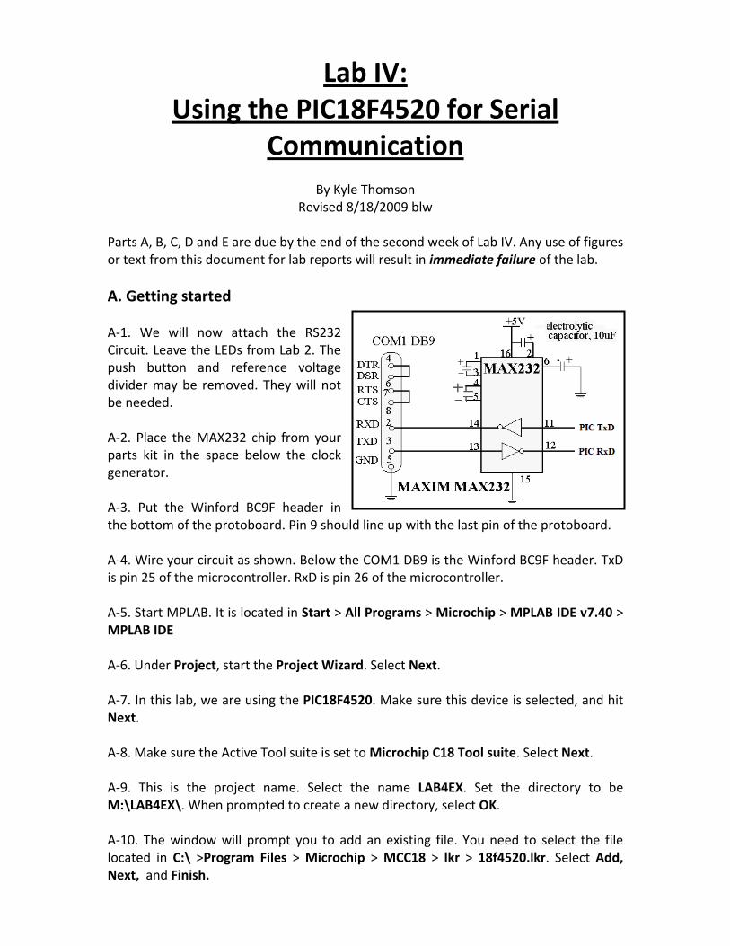
Parts A, B, C, D and E are due by the end of the second week of Lab IV. Any use of figures or text from this document for lab reports will result in immediate failure of the lab. A. Getting started A-1. We will now attach the RS232 Circuit. Leave the LEDs from Lab 2. The push button and reference voltage divider may be removed. They will not be needed. A-2. Place the MAX232 chip from your parts kit in the space below the clock generator. A-3. Put the Winford BC9F header in the bottom of the protoboard. Pin 9 should line up with the last pin of the protoboard. A-4. Wire your circuit as shown. Below the COM1 DB9 is the Winford BC9F header. TxD is pin 25 of the microcontroller. RxD is pin 26 of the microcontroller. A-5. Start MPLAB. It is located in Start > All Programs > Microchip > MPLAB IDE v7.40 > MPLAB IDE A-6. Under Project, start the Project Wizard. Select Next. A-7. In this lab, we are using the PIC18F4520. Make sure this device is selected, and hit Next. A-8. Make sure the Active Tool suite is set to Microchip C18 Tool suite. Select Next. A-9. This is the project name. Select the name LAB4EX. Set the directory to be M:\LAB4EX\. When prompted to create a new directory, select OK. A-10. The window will prompt you to add an existing file. You need to select the file located in C:\ >Program Files > Microchip > MCC18 > lkr > 18f4520.lkr. Select Add, Next, and Finish.
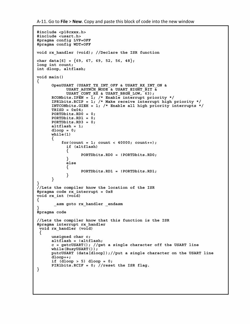
A-11. Go to File > New. Copy and paste this block of code into the new window #include <p18cxxx.h> #include <usart.h> #pragma config LVP=OFF #pragma config WDT=OFF void rx_handler (void); //Declare the ISR function char data[6] = {69, 67, 69, 52, 56, 48}; long int count; int dloop, altflash; void main() { OpenUSART (USART_TX_INT_OFF & USART_RX_INT_ON & USART_ASYNCH_MODE & USART_EIGHT_BIT & USART_CONT_RX & USART_BRGH_LOW, 63); RCONbits.IPEN = 1; /* Enable interrupt priority */ IPR1bits.RCIP = 1; /* Make receive interrupt high priority */ INTCONbits.GIEH = 1; /* Enable all high priority interrupts */ TRISD = 0x04; PORTDbits.RD0 = 0; PORTDbits.RD1 = 0; PORTDbits.RD3 = 0; altflash = 1; dloop = 0; while(1) { for(count = 1; count < 40000; count++); if (altflash) { PORTDbits.RD0 = !PORTDbits.RD0; } else { PORTDbits.RD1 = !PORTDbits.RD1; } } } //Lets the compiler know the location of the ISR #pragma code rx_interrupt = 0x8 void rx_int (void) { _asm goto rx_handler _endasm } #pragma code //Lets the compiler know that this function is the ISR #pragma interrupt rx_handler void rx_handler (void) { unsigned char c; altflash = !altflash; c = getcUSART(); //get a single character off the USART line while(BusyUSART()); putcUSART (data[dloop]);//put a single character on the USART line dloop++; if (dloop > 5) dloop = 0; PIR1bits.RCIF = 0; //reset the ISR flag. }

A-12. Go to File > Save. Type the file name as M:\LAB4EX\LAB4.c. Select the check box at the bottom labeled Add File to Project. Select Save A-13. We now need to create our visual basic project. On the ECE480 Mini Projects website, there is a visual basic zip file named LAB4VB.zip. Right Click the file, and select Open. Press the
Extract button. Type the directory M:\LAB4VB, so the screen looks like the right. Press Extract on the right.
A-14. Locate the LAB4VB directory on your M:\ Drive. Double Click the file named SampleSerial. It will be noted as a Visual Basic 2008 Project. Visual Studio 2008 will open. (see Note) For future reference, Visual Studio 2008 can be accessed by Start > All Programs > Microsoft Visual Studio 2008 > Microsoft Visual
Studio 2008
A-15. On the right will be a list of files. Double Click the file noted Form1.vb. This will open a VB file on the left that looks like the figure to the left. Double click the button on the form. This will open the code window.
A-16. The code located here is the code executed when the button is pressed. Note that the label of the button is GetSerial, however the name of the button is Button1. This will be discussed later in the lab. Note: When opening a VS 2008 file from your samba file space you may get a caution window stating that the project location is not trusted. Click OK to continue.
A-17. Turn on the Hewlett Packard DC Power Supply. Press the +6V button under METER. Set this to 5V using the +6V dial. Turn the power supply back off. Connect a black banana-to-banana connector from COM to the Green Ground. Plug a black banana-to-grabber from the COM to your protoboard’s ground. Plug a red banana-to-grabber from the +6V to your protoboard’s Vdd. It is now time to turn on the power supply.
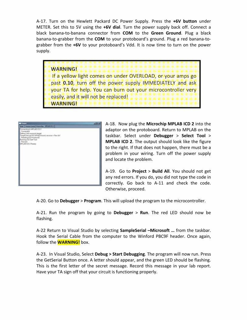
WARNING! If a yellow light comes on under OVERLOAD, or your amps go past 0.10, turn off the power supply IMMEDIATELY and ask your TA for help. You can burn out your microcontroller very easily, and it will not be replaced! WARNING!
A-18. Now plug the Microchip MPLAB ICD 2 into the adaptor on the protoboard. Return to MPLAB on the taskbar. Select under Debugger > Select Tool > MPLAB ICD 2. The output should look like the figure to the right. If that does not happen, there must be a problem in your wiring. Turn off the power supply and locate the problem. A-19. Go to Project > Build All. You should not get any red errors. If you do, you did not type the code in correctly. Go back to A-11 and check the code. Otherwise, proceed.
A-20. Go to Debugger > Program. This will upload the program to the microcontroller. A-21. Run the program by going to Debugger > Run. The red LED should now be flashing. A-22 Return to Visual Studio by selecting SampleSerial –Microsoft … from the taskbar. Hook the Serial Cable from the computer to the Winford PBC9F header. Once again, follow the WARNING! box. A-23. In Visual Studio, Select Debug > Start Debugging. The program will now run. Press the GetSerial Button once. A letter should appear, and the green LED should be flashing. This is the first letter of the secret message. Record this message in your lab report. Have your TA sign off that your circuit is functioning properly.

B. Protocol & GUI Development B-1. We will now develop a protocol, or a method of interaction between two separate devices, for our GUI. Initially, we sent a ‘b’ to the PIC microcontroller, and the PIC sent back a character. The PIC discards the ‘b’ that is sent. However, we can use this sent value to direct the PIC towards the information we want. B-2. Stop the running program in Visual Basic by clicking the in the top right corner. This will return you back to the design screen. Right click on the GetSerial Button. Select Copy. Right click on an open space in the Form window. Select Paste. A second GetSerial Button will appear.
B-3. We now want to change some properties of the second GetSerial Button. Select the new GetSerial Button. The bottom right panel contains information about this button. Lets first change the label, so we can differentiate between the two buttons. Locate the field that says text, and change it to Data 2, as shown on the left. Next, locate the field that says (NAME). Change this to Data2, as shown on the right.
B-4. Double click the Data 2 Button. This will bring up the code for our new button. Copy and paste the following code into the blank space given. It will look like the figure to the right after we are done.
setRs232.Write("c") setRs232.Read(1) serial_in = setRs232.InputStreamString TextBox1.Text = serial_in
B-5. We now need to modify our PIC code. Return to MPLAB and stop the program by
pressing the pause button. Make the following changes to the code. Replace ? with the number of letters in your first name. Replace the letters in ‘N’, ‘a’, ‘m’, ‘e’ with the letters of your first name. Be sure to follow the same syntax.
char data[6] = {69, 67, 69, 52, 56, 48}; char data2[?] = {'N','a','m','e'}; long int count; int dloop, dloop2, altflash;
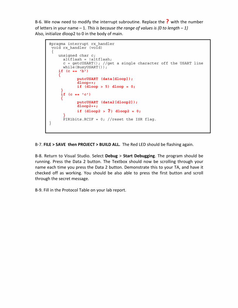
B-6. We now need to modify the interrupt subroutine. Replace the ? with the number of letters in your name – 1. This is because the range of values is {0 to length – 1} Also, initialize dloop2 to 0 in the body of main.
#pragma interrupt rx_handler void rx_handler (void) { unsigned char c; altflash = !altflash; c = getcUSART(); //get a single character off the USART line while(BusyUSART()); if (c == 'b') { putcUSART (data[dloop]); dloop++; if (dloop > 5) dloop = 0; } if (c == 'c') { putcUSART (data2[dloop2]); dloop2++;
if (dloop2 > ?) dloop2 = 0; } PIR1bits.RCIF = 0; //reset the ISR flag. }
B-7. FILE > SAVE then PROJECT > BUILD ALL. The Red LED should be flashing again. B-8. Return to Visual Studio. Select Debug > Start Debugging. The program should be running. Press the Data 2 button. The Textbox should now be scrolling through your name each time you press the Data 2 button. Demonstrate this to your TA, and have it checked off as working. You should be also able to press the first button and scroll through the secret message. B-9. Fill in the Protocol Table on your lab report.
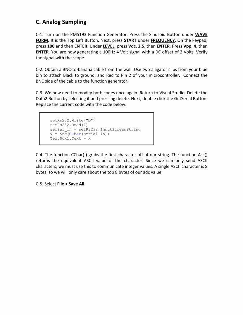
C. Analog Sampling C-1. Turn on the PM5193 Function Generator. Press the Sinusoid Button under WAVE FORM. It is the Top Left Button. Next, press START under FREQUENCY. On the keypad, press 100 and then ENTER. Under LEVEL, press Vdc, 2.5, then ENTER. Press Vpp, 4, then ENTER. You are now generating a 100Hz 4 Volt signal with a DC offset of 2 Volts. Verify the signal with the scope. C-2. Obtain a BNC-to-banana cable from the wall. Use two alligator clips from your blue bin to attach Black to ground, and Red to Pin 2 of your microcontroller. Connect the BNC side of the cable to the function generator. C-3. We now need to modify both codes once again. Return to Visual Studio. Delete the Data2 Button by selecting it and pressing delete. Next, double click the GetSerial Button. Replace the current code with the code below.
setRs232.Write("b") setRs232.Read(1) serial_in = setRs232.InputStreamString x = Asc(CChar(serial_in)) TextBox1.Text = x
C-4. The function CChar( ) grabs the first character off of our string. The function Asc() returns the equivalent ASCII value of the character. Since we can only send ASCII characters, we must use this to communicate integer values. A single ASCII character is 8 bytes, so we will only care about the top 8 bytes of our adc value. C-5. Select File > Save All

C-6. We now need to modify our MPLAB code. Replace all of the code with the following. #include <p18cxxx.h> #include <usart.h> #include <ADC.h> #pragma config LVP=OFF #pragma config WDT=OFF void rx_handler (void); //Declare the ISR function long int count; int adc_result, altflash; unsigned char data; void main() { OpenUSART (USART_TX_INT_OFF & USART_RX_INT_ON & USART_ASYNCH_MODE & USART_EIGHT_BIT & USART_CONT_RX & USART_BRGH_LOW, 63); RCONbits.IPEN = 1; /* Enable interrupt priority */ IPR1bits.RCIP = 1; /* Make receive interrupt high priority */ INTCONbits.GIEH = 1; /* Enable all high priority interrupts */ OpenADC(ADC_FOSC_32 & ADC_RIGHT_JUST & ADC_12_TAD, ADC_CH0 & ADC_INT_OFF, 0); //open adc port for reading ADCON1 =0x00; //set VREF+ to VDD and VREF- to GND (VSS) TRISD = 0x04; PORTDbits.RD0 = 0; PORTDbits.RD1 = 0; PORTDbits.RD3 = 0; altflash = 1; while(1) { for(count = 1; count < 40000; count++); if (altflash) { PORTDbits.RD0 = !PORTDbits.RD0; } else { PORTDbits.RD1 = !PORTDbits.RD1; } } } #pragma code rx_interrupt = 0x8 void rx_int (void) { _asm goto rx_handler _endasm } #pragma code #pragma interrupt rx_handler void rx_handler (void) { unsigned char c; altflash = !altflash; c = getcUSART(); //get a single character off the USART line while(BusyUSART()); ConvertADC(); //perform ADC conversion while(BusyADC()); //wait for result adc_result = ReadADC(); //get ADC result data = adc_result >> 2; putcUSART (data); //put a single character on the USART line PIR1bits.RCIF = 0; //reset the ISR flag. }
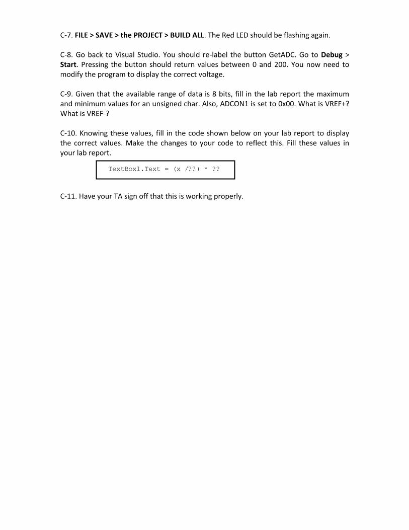
C-7. FILE > SAVE > the PROJECT > BUILD ALL. The Red LED should be flashing again. C-8. Go back to Visual Studio. You should re-label the button GetADC. Go to Debug > Start. Pressing the button should return values between 0 and 200. You now need to modify the program to display the correct voltage. C-9. Given that the available range of data is 8 bits, fill in the lab report the maximum and minimum values for an unsigned char. Also, ADCON1 is set to 0x00. What is VREF+? What is VREF-? C-10. Knowing these values, fill in the code shown below on your lab report to display the correct values. Make the changes to your code to reflect this. Fill these values in your lab report.
TextBox1.Text = (x /??) * ?? C-11. Have your TA sign off that this is working properly.

D. Analog Graphing D-1. Stop your visual basic program. Delete the textbox by selecting it and pressing the delete button. D-2. To install the Dundas Chart tools, Go to Tools> Chose Toolbox Items. Select Browse and add the following file DundasWinChart.dll. This will add the file under the name “Chart” with the namespace “Dundas.Charting.WinControl”. Verify there is a check next to the name “Chart”. Select OK. D-3 Go to View> ToolBox. Under the General tab you will see the Dundas chart tools. Double click on “Chart”. A box like below will appear. Under Chart Type Group, select Line. Press Finish. You may need to arrange your Form, and change the size. You can click the button and chart to drag them and resize them. Additionally, the form may be resized.
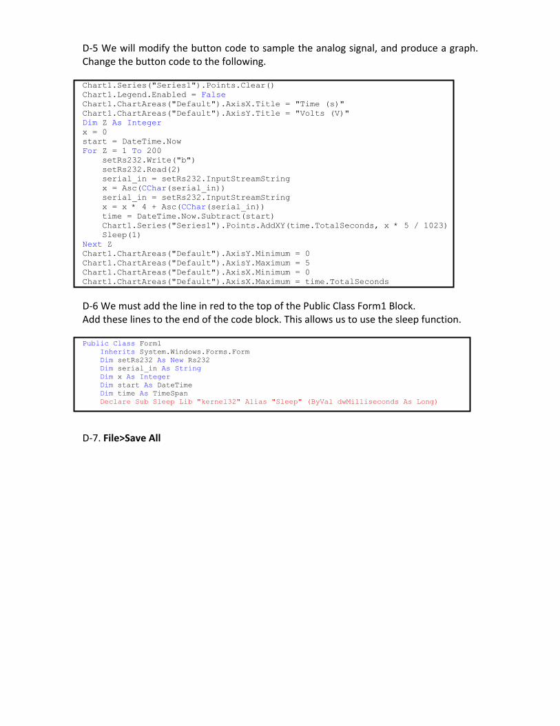
D-5 We will modify the button code to sample the analog signal, and produce a graph. Change the button code to the following. Chart1.Series("Series1").Points.Clear() Chart1.Legend.Enabled = False Chart1.ChartAreas("Default").AxisX.Title = "Time (s)" Chart1.ChartAreas("Default").AxisY.Title = "Volts (V)" Dim Z As Integer x = 0 start = DateTime.Now For Z = 1 To 200 setRs232.Write("b") setRs232.Read(2) serial_in = setRs232.InputStreamString x = Asc(CChar(serial_in)) serial_in = setRs232.InputStreamString x = x * 4 + Asc(CChar(serial_in)) time = DateTime.Now.Subtract(start) Chart1.Series("Series1").Points.AddXY(time.TotalSeconds, x * 5 / 1023) Sleep(1) Next Z Chart1.ChartAreas("Default").AxisY.Minimum = 0 Chart1.ChartAreas("Default").AxisY.Maximum = 5 Chart1.ChartAreas("Default").AxisX.Minimum = 0 Chart1.ChartAreas("Default").AxisX.Maximum = time.TotalSeconds
D-6 We must add the line in red to the top of the Public Class Form1 Block. Add these lines to the end of the code block. This allows us to use the sleep function. Public Class Form1 Inherits System.Windows.Forms.Form Dim setRs232 As New Rs232 Dim serial_in As String Dim x As Integer Dim start As DateTime Dim time As TimeSpan Declare Sub Sleep Lib "kernel32" Alias "Sleep" (ByVal dwMilliseconds As Long)
D-7. File>Save All

D-7 Now we will modify our MPLAB code. Replace all of your code with the following. #include <p18cxxx.h> #include <usart.h> #include <ADC.h> #pragma config LVP=OFF #pragma config WDT=OFF void rx_handler (void); //Declare the ISR function long int count; int adc_result; unsigned char data; void main() { OpenUSART (USART_TX_INT_OFF & USART_RX_INT_ON & USART_ASYNCH_MODE & USART_EIGHT_BIT & USART_CONT_RX & USART_BRGH_LOW, 63); RCONbits.IPEN = 1; /* Enable interrupt priority */ IPR1bits.RCIP = 1; /* Make receive interrupt high priority */ INTCONbits.GIEH = 1; /* Enable all high priority interrupts */ OpenADC(ADC_FOSC_32 & ADC_RIGHT_JUST & ADC_12_TAD, ADC_CH0 & ADC_INT_OFF, 0); //open adc port for reading ADCON1 =0x00; //set VREF+ to VDD and VREF- to GND (VSS) TRISD = 0x04; PORTDbits.RD0 = 0; PORTDbits.RD1 = 0; PORTDbits.RD3 = 0; while(1); } #pragma code rx_interrupt = 0x8 void rx_int (void) { _asm goto rx_handler _endasm } #pragma code #pragma interrupt rx_handler void rx_handler (void) { unsigned char c; c = getcUSART(); //get a single character off the USART line while(BusyUSART()); ConvertADC(); //perform ADC conversion while(BusyADC()); //wait for result adc_result = ReadADC(); //get ADC result data = adc_result >> 2;
putcUSART (data); //put a single character on the USART line data = adc_result & 0x0003; putcUSART (data); PIR1bits.RCIF = 0; //reset the ISR flag. }

D-8 File > Save All D-9 Project > Build All D-10 Set the Function generator to a X Hz signal with a DC offset of 2 Volts and a peak to peak of 2 Volts. X is the last number of your PID. (0 is 10). D-11 Run the Visual Basic program by going to Debug > Start. Press the button. You should have the graph of a signal. Hold Alt and press the Print Scrn button on the top right of the keyboard. D-12 Open Paint by going to Start > All Programs > Accessories > Paint. D-13 Select Edit > Paste. Make sure that the plot is set up to print on one page. Then Select File > Print > Print. Write D-10 at the top of this graph, and hand it in with your lab report.

E. Mini-Project E-1 Your project will consist of a GUI that will be able to do all of the following:
1. Send the individual letters of your last name to a text box. 2. Turn on and off each of the 3 LEDs. 3. Sample a single Analog value 4. Graph a 1-10 Hz signal. The value for the sleep function and the value for the
number of samples must be adjustable. To read a value from a textbox, use the function val. (Val() – Converts Text in a textbox to its associated integer value. For example: “1234” becomes 1234, and “23 6” becomes 236.)
E-2 You will need to write a lab report that contains a schematic, and a protocol table. Additionally, any Form Code you wrote needs to be commented and included. E-3 Have your TA sign off that your mini project is working.
Lab Report
Lab IV – Using the PIC18F4520 for Serial Communication Name: . . . . . . . . . . . . . . . . . . . . . . . . . . . . . . . . . . . . . . . . . . . . . . . . . . . . . . . . . . . Date: . . . . . . . . . . . . . . . . . . . . . . . . . . . . . . . . . . . . . . . . . . . . . . . . . . . . . . . . . . . . Lab Section Number . . . . . . . . . . . . . . . . . . . . . . . . . . . . . . . . . . . . . . . . . . . . . . .
Code of Ethics Declaration
All of the attached work was performed by me as listed above. I did not obtain any information or data from any other student in this lab or any other lab. Signature . . . . . . . . . . . . . . . . . . . . . . . . . . . . . . . . . . . . . . . . . . . . . . . . . . . . . . . . A-23 I, _________________ (Lab instructor’s initials) verify that part A is working correctly. Secret Message: ___ ___ ___ ___ ___ ___
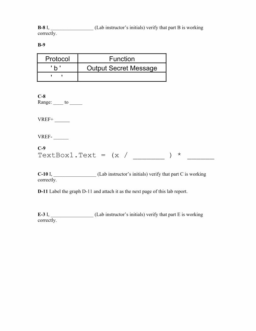
B-8 I, _________________ (Lab instructor’s initials) verify that part B is working correctly. B-9
Protocol Function ' b ' Output Secret Message ' '
C-8 Range: ____ to _____ VREF+ ______ VREF- ______ C-9 TextBox1.Text = (x / _______ ) * ______ C-10 I, _________________ (Lab instructor’s initials) verify that part C is working correctly. D-11 Label the graph D-11 and attach it as the next page of this lab report. E-3 I, _________________ (Lab instructor’s initials) verify that part E is working correctly.