lab 3.2.5.2 use network inspector to observe stp behavioraskoik.kapsi.fi/koulu/suoritetut kurssit 4....
TRANSCRIPT
1 - 17 CCNP 3: Multilayer Switching v 4.0 - Lab 3.2.5.2 Copyright © 2005, Cisco Systems, Inc.
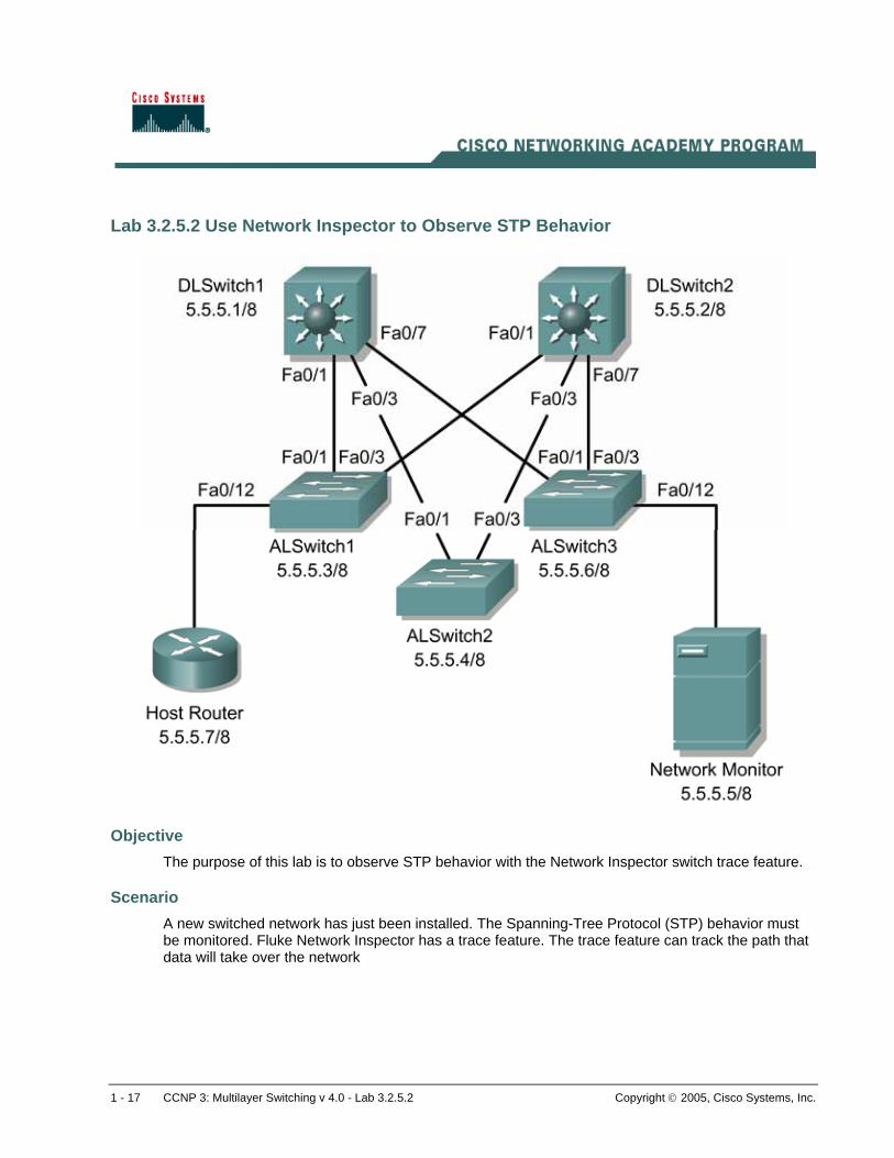
Lab 3.2.5.2 Use Network Inspector to Observe STP Behavior
Objective The purpose of this lab is to observe STP behavior with the Network Inspector switch trace feature.
Scenario A new switched network has just been installed. The Spanning-Tree Protocol (STP) behavior must be monitored. Fluke Network Inspector has a trace feature. The trace feature can track the path that data will take over the network

2 - 17 CCNP 3: Multilayer Switching v 4.0 - Lab 3.2.5.2 Copyright © 2005, Cisco Systems, Inc.
The network design is as follows.
Switch VTP Domain VTP Mode
DLSwitch1 CORP Server
DLSwitch2 CORP Client
ALSwitch1 CORP Client
ALSwitch2 CORP Client
ALSwitch3 CORP Client
The VLAN configuration information is as follows.
VLAN ID VLAN Name VLAN Subnet DLSwitch ALSwitch
1 Native 5.0.0.0/8 All Ports All Ports
Trunk 802.1q
Device DLSwitch1 DLSwitch2 ALSwitch1 ALSwitch2 ALSwitch3 Network
InspectorHost Router
IP address
5.5.5.1/8 5.5.5.2/8 5.5.5.3/8 5.5.5.4/8 5.5.5.6/8 5.5.5.5/8 5.5.5.7/8
Step 1 Cable the lab according to the diagram.
Before configuring the switches, delete the vlan.dat database file and power cycle each switch. Then erase the startup configuration on each switch and issue the reload command.
DLSwitch1#delete flash Delete filename [flash]? vlan.dat DLSwitch1#erase start DLSwitch1#reload
Note: Do not save the configuration changes when prompted.
Configure the hostname, passwords, and Telnet access to all the switches. Use interface vlan 1 to configure the IP address of all the switches.
Switch(config)#hostname DLSwitch1 DLSwitch1(config)#enable secret cisco DLSwitch1(config)#line console 0 DLSwitch1(config-line)#password cisco DLSwitch1(config-line)#login DLSwitch1(config-line)#line vty 0 15 DLSwitch1(config-line)#password cisco DLSwitch1(config-line)#login DLSwitch1(config-line)#interface vlan 1 DLSwitch1(config-if)#ip address 5.5.5.1 255.0.0.0 DLSwitch1(config-if)#no shutdown

3 - 17 CCNP 3: Multilayer Switching v 4.0 - Lab 3.2.5.2 Copyright © 2005, Cisco Systems, Inc.
DLSwitch1(config-if)#^Z Switch(config)#hostname DLSwitch2 DLSwitch2(config)#enable secret cisco DLSwitch2(config)#line console 0 DLSwitch2(config-line)#password cisco DLSwitch2(config-line)#login DLSwitch2(config-line)#line vty 0 15 DLSwitch2(config-line)#password cisco DLSwitch2(config-line)#login DLSwitch2(config-line)#interface vlan 1 DLSwitch2(config-if)#ip address 5.5.5.2 255.0.0.0 DLSwitch2(config-if)#no shutdown DLSwitch2(config-if)#^Z
Switch(config)#hostname ALSwitch1 ALSwitch1(config)#enable secret cisco ALSwitch1(config)#line console 0 ALSwitch1(config-line)#password cisco ALSwitch1(config-line)#login ALSwitch1(config-line)#line vty 0 15 ALSwitch1(config-line)#password cisco ALSwitch1(config-line)#login ALSwitch1(config-line)#interface vlan 1 ALSwitch1(config-if)#ip address 5.5.5.3 255.0.0.0 ALSwitch1(config-if)#no shutdown ALSwitch1(config-if)#^Z
Switch(config)#hostname ALSwitch2 ALSwitch2(config)#enable secret cisco ALSwitch2(config)#line console 0 ALSwitch2(config-line)#password cisco ALSwitch2(config-line)#login ALSwitch2(config-line)#line vty 0 15 ALSwitch2(config-line)#password cisco ALSwitch2(config-line)#login ALSwitch2(config-line)#interface vlan 1 ALSwitch2(config-if)#ip address 5.5.5.4 255.0.0.0 ALSwitch2(config-if)#no shutdown
ALSwitch2(config-if)#^Z
Switch(config)#hostname ALSwitch3 ALSwitch3(config)#enable secret cisco ALSwitch3(config)#line console 0 ALSwitch3(config-line)#password cisco ALSwitch3(config-line)#login ALSwitch3(config-line)#line vty 0 15 ALSwitch3(config-line)#password cisco ALSwitch3(config-line)#login ALSwitch3(config)#interface vlan 1 ALSwitch3(config-if)#ip address 5.5.5.6 255.0.0.0 ALSwitch3(config-if)#no shutdown ALSwitch3(config-if)#^Z

4 - 17 CCNP 3: Multilayer Switching v 4.0 - Lab 3.2.5.2 Copyright © 2005, Cisco Systems, Inc.
Step 2 Configure the trunking interfaces.
Create a trunk link between the switches. On the DLSwitch1 and DLSwitch2 set the port to trunking with the 802.1q encapsulation.
Note If an error is received, it is because the port is set to auto encapsulation. Fix the error by entering the switchport mode trunk command after the switchport trunk encapsulation dot1q command.
DLSwitch1(config)#interface FastEthernet 0/1 DLSwitch1(config-if)#switchport mode trunk DLSwitch1(config-if)#switchport trunk encapsulation dot1q DLSwitch1(config-if)#interface FastEthernet 0/3 DLSwitch1(config-if)#switchport mode trunk DLSwitch1(config-if)#switchport trunk encapsulation dot1q DLSwitch1(config-if)#interface FastEthernet 0/7 DLSwitch1(config-if)#switchport mode trunk DLSwitch1(config-if)#switchport trunk encapsulation dot1q DLSwitch1(config-if)#^Z DLSwitch2(config)#interface FastEthernet 0/1 DLSwitch2(config-if)#switchport mode trunk DLSwitch2(config-if)#switchport trunk encapsulation dot1q DLSwitch2(config-if)#interface FastEthernet 0/3 DLSwitch2(config-if)#switchport mode trunk DLSwitch2(config-if)#switchport trunk encapsulation dot1q DLSwitch2(config-if)#interface FastEthernet 0/7 DLSwitch2(config-if)#switchport mode trunk DLSwitch2(config-if)#switchport trunk encapsulation dot1q DLSwitch2(config-if)#^Z
The access layer switches do not need the encapsulation configured. It defaults to 802.1q. In some IOS versions there are no other options.
ALSwitch1(config)#interface FastEthernet0/1 ALSwitch1(config-if)#switchport mode trunk ALSwitch1(config-if)#interface FastEthernet 0/3 ALSwitch1(config-if)#switchport mode trunk ALSwitch1(config-if)#^Z ALSwitch2(config)#interface fastethernet 0/1 ALSwitch2(config-if)#switchport mode trunk ALSwitch2(config-if)#interface fastethernet 0/3 ALSwitch2(config-if)#switchport mode trunk ALSwitch2(config-if)#^Z ALSwitch3(config)#interface fastethernet 0/1 ALSwitch3(config-if)#switchport mode trunk ALSwitch3(config-if)#interface fastethernet 0/3 ALSwitch3(config-if)#switchport mode trunk ALSwitch3(config-if)#^Z
Verify the trunk configuration with the show vtp counters command. DLSwitch1#show vtp counters VTP statistics: Summary advertisements received : 0 Subset advertisements received : 0

5 - 17 CCNP 3: Multilayer Switching v 4.0 - Lab 3.2.5.2 Copyright © 2005, Cisco Systems, Inc.
Request advertisements received : 0 Summary advertisements transmitted : 0 Subset advertisements transmitted : 0 Request advertisements transmitted : 0 Number of config revision errors : 0 Number of config digest errors : 0 Number of V1 summary errors : 0 VTP pruning statistics: Trunk Join Transmitted Join Received Summary advts received from non-pruning-capable device ------------- ---------------- ---------------- --------------------------- Fa0/1 0 0 0 Fa0/3 0 0 0 Fa0/7 0 0 0
Verify the configuration on all the switches. DLSwitch1#show vtp counters <Output omitted> VTP pruning statistics: Trunk Join Transmitted Join Received Summary advts received from non-pruning-capable device ---------------- ---------------- ---------------- --------------------------- Fa0/1 0 0 0 Fa0/3 0 0 0Fa0/7 0 0 0
DLSwitch2#show vtp counters <Output omitted> VTP pruning statistics: Trunk Join Transmitted Join Received Summary advts received from non-pruning-capable device ---------------- ---------------- ---------------- --------------------------- Fa0/1 0 0 0 Fa0/3 0 0 0 Fa0/7 0 0 0
ALSwitch1#show vtp counters <Output omitted> VTP pruning statistics: Trunk Join Transmitted Join Received Summary advts received from non-pruning-capable device ---------------- ---------------- ---------------- --------------------------- Fa0/1 0 0 0
Fa0/3 0 0 0
ALSwitch2#show vtp counters <Output omitted> VTP pruning statistics: Trunk Join Transmitted Join Received Summary advts received from non-pruning-capable device ---------------- ---------------- ---------------- --------------------------- Fa0/1 0 0 0 Fa0/3 0 0 0
6 - 17 CCNP 3: Multilayer Switching v 4.0 - Lab 3.2.5.2 Copyright © 2005, Cisco Systems, Inc.
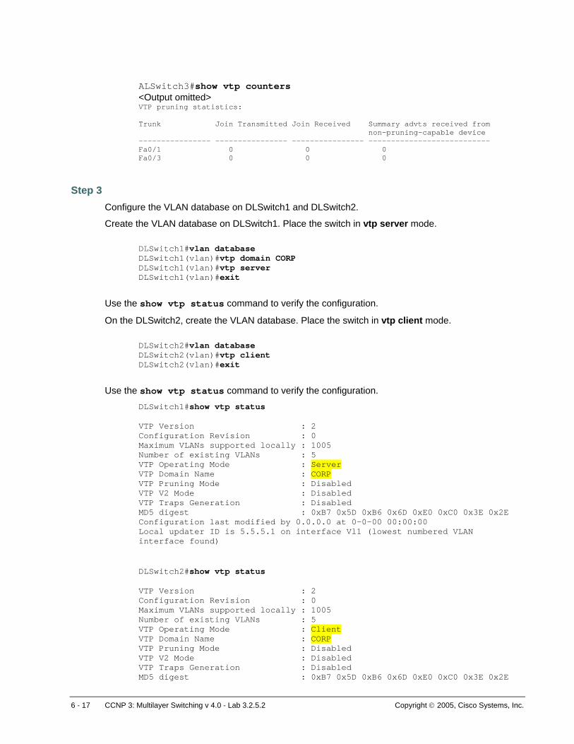
ALSwitch3#show vtp counters <Output omitted> VTP pruning statistics: Trunk Join Transmitted Join Received Summary advts received from non-pruning-capable device ---------------- ---------------- ---------------- --------------------------- Fa0/1 0 0 0 Fa0/3 0 0 0
Step 3 Configure the VLAN database on DLSwitch1 and DLSwitch2.
Create the VLAN database on DLSwitch1. Place the switch in vtp server mode. DLSwitch1#vlan database DLSwitch1(vlan)#vtp domain CORP DLSwitch1(vlan)#vtp server DLSwitch1(vlan)#exit
Use the show vtp status command to verify the configuration.
On the DLSwitch2, create the VLAN database. Place the switch in vtp client mode. DLSwitch2#vlan database DLSwitch2(vlan)#vtp client DLSwitch2(vlan)#exit
Use the show vtp status command to verify the configuration. DLSwitch1#show vtp status VTP Version : 2 Configuration Revision : 0 Maximum VLANs supported locally : 1005 Number of existing VLANs : 5 VTP Operating Mode : Server VTP Domain Name : CORP VTP Pruning Mode : Disabled VTP V2 Mode : Disabled VTP Traps Generation : Disabled MD5 digest : 0xB7 0x5D 0xB6 0x6D 0xE0 0xC0 0x3E 0x2E Configuration last modified by 0.0.0.0 at 0-0-00 00:00:00 Local updater ID is 5.5.5.1 on interface Vl1 (lowest numbered VLAN interface found)
DLSwitch2#show vtp status VTP Version : 2 Configuration Revision : 0 Maximum VLANs supported locally : 1005 Number of existing VLANs : 5 VTP Operating Mode : Client VTP Domain Name : CORP VTP Pruning Mode : Disabled VTP V2 Mode : Disabled VTP Traps Generation : Disabled MD5 digest : 0xB7 0x5D 0xB6 0x6D 0xE0 0xC0 0x3E 0x2E

7 - 17 CCNP 3: Multilayer Switching v 4.0 - Lab 3.2.5.2 Copyright © 2005, Cisco Systems, Inc.
Configuration last modified by 0.0.0.0 at 0-0-00 00:00:00
Step 4 Configure the VLAN database on the access layer switches. Place them in client mode.
ALSwitch1#vlan database ALSwitch1(vlan)#vtp client ALSwitch1(vlan)#exit
ALSwitch2#vlan database ALSwitch2(vlan)#vtp client ALSwitch2(vlan)#exit ALSwitch3#vlan database ALSwitch3(vlan)#vtp client ALSwitch3(vlan)#exit
Verify the vtp configuration with the show vtp status command on all the switches. ALSwitch1#show vtp status VTP Version : 2 Configuration Revision : 0 Maximum VLANs supported locally : 250 Number of existing VLANs : 5 VTP Operating Mode : Client VTP Domain Name : CORP VTP Pruning Mode : Disabled VTP V2 Mode : Disabled VTP Traps Generation : Disabled MD5 digest : 0xB7 0x5D 0xB6 0x6D 0xE0 0xC0 0x3E 0x2E Configuration last modified by 0.0.0.0 at 0-0-00 00:00:00
ALSwitch2#show vtp status VTP Version : 2 Configuration Revision : 0 Maximum VLANs supported locally : 250 Number of existing VLANs : 5 VTP Operating Mode : Client VTP Domain Name : CORP VTP Pruning Mode : Disabled VTP V2 Mode : Disabled VTP Traps Generation : Disabled MD5 digest : 0xB7 0x5D 0xB6 0x6D 0xE0 0xC0 0x3E 0x2E
Configuration last modified by 0.0.0.0 at 0-0-00 00:00:00
ALSwitch3#show vtp status VTP Version : 2 Configuration Revision : 0 Maximum VLANs supported locally : 250 Number of existing VLANs : 5 VTP Operating Mode : Client VTP Domain Name : CORP VTP Pruning Mode : Disabled VTP V2 Mode : Disabled VTP Traps Generation : Disabled MD5 digest : 0xB7 0x5D 0xB6 0x6D 0xE0 0xC0 0x3E 0x2E
Configuration last modified by 0.0.0.0 at 0-0-00 00:00:00

8 - 17 CCNP 3: Multilayer Switching v 4.0 - Lab 3.2.5.2 Copyright © 2005, Cisco Systems, Inc.
Step 5 Configure DLSwitch1 as the root bridge.
Change the root bridge priority to 4096 on DLSwitch1. DLSwitch1(config)#spanning-tree vlan 1 priority 4096 DLSwitch1(config)#^Z
Verify that DLSwitch1 is the root bridge with the show spanning-tree command.
DLSwitch1#show spanning-tree VLAN0001 Spanning tree enabled protocol ieee Root ID Priority 4097 Address 000b.be4f.bc00 This bridge is the root Hello Time 2 sec Max Age 20 sec Forward Delay 15 sec Bridge ID Priority 4097 (priority 4096 sys-id-ext 1) Address 000b.be4f.bc00 Hello Time 2 sec Max Age 20 sec Forward Delay 15 sec Aging Time 300 Interface Port ID Designated Port ID Name Prio.Nbr Cost Sts Cost Bridge ID Prio.Nbr -------------- -------- --------- --- ------- -------------------- -------- Fa0/1 128.1 19 FWD 0 4097 000b.be4f.bc00 128.1 Fa0/3 128.3 19 FWD 0 4097 000b.be4f.bc00 128.3 Fa0/7 128.7 19 FWD 0 4097 000b.be4f.bc00 128.7
Step 6 Configure the HostRouter. The router is only acting as a host device. It will be used as an end device to which to trace.
Router(config)#hostname HostRouter HostRouter(config)#interface fa0/0 HostRouter(config-if)#ip address 5.5.5.7 255.0.0.0 HostRouter(config-if)#no shutdown HostRouter(config-if)#exit
Step 7 Fluke Network Inspector can be used to monitor the behavior of the switched network. Monitoring is important in successful network management. For this lab, use the Trace SwitchRoute feature to monitor STP.
Run Fluke Network Inspector console from the Start menu or from a desktop shortcut. The screen should look like the following image.

9 - 17 CCNP 3: Multilayer Switching v 4.0 - Lab 3.2.5.2 Copyright © 2005, Cisco Systems, Inc.
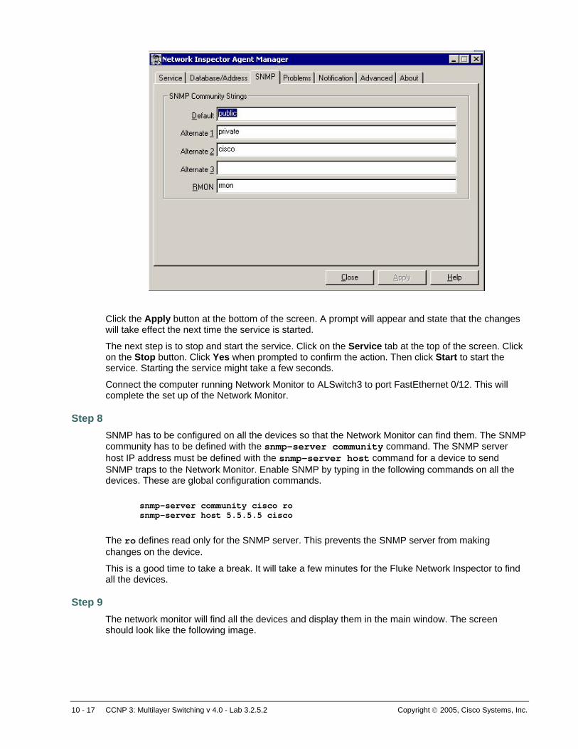
First, a community string must be defined. A public community string may be defined by default. For security purposes, it is highly recommend that a different community string be selected. Click on the Agent tab at the top of the console to get the following screen.
Then click on the SNMP tab. Type cisco as an alternative community string. It may be necessary to enter cisco as the Default SNMP Community String on older versions of NI.
10 - 17 CCNP 3: Multilayer Switching v 4.0 - Lab 3.2.5.2 Copyright © 2005, Cisco Systems, Inc.
Click the Apply button at the bottom of the screen. A prompt will appear and state that the changes will take effect the next time the service is started.
The next step is to stop and start the service. Click on the Service tab at the top of the screen. Click on the Stop button. Click Yes when prompted to confirm the action. Then click Start to start the service. Starting the service might take a few seconds.
Connect the computer running Network Monitor to ALSwitch3 to port FastEthernet 0/12. This will complete the set up of the Network Monitor.
Step 8 SNMP has to be configured on all the devices so that the Network Monitor can find them. The SNMP community has to be defined with the snmp-server community command. The SNMP server host IP address must be defined with the snmp-server host command for a device to send SNMP traps to the Network Monitor. Enable SNMP by typing in the following commands on all the devices. These are global configuration commands.
snmp-server community cisco ro snmp-server host 5.5.5.5 cisco
The ro defines read only for the SNMP server. This prevents the SNMP server from making changes on the device.
This is a good time to take a break. It will take a few minutes for the Fluke Network Inspector to find all the devices.
Step 9 The network monitor will find all the devices and display them in the main window. The screen should look like the following image.

11 - 17 CCNP 3: Multilayer Switching v 4.0 - Lab 3.2.5.2 Copyright © 2005, Cisco Systems, Inc.
Network Monitor will display the hostname, IP address, MAC address, and the type of device on the right side of the screen. If the device type does not appear, change it by right clicking the device and selecting Modify Type. If the device IP address is displayed instead of the hostname, then enter the following command on the device. It will send the hostname to the Network Monitor.
snmp-server chassis-id [device hostname]
Next, start the switch trace. Select host 5.5.5.5 by clicking on it and highlighting it. This will be the starting device for the trace. Then, click on the Trace SR button on top of the screen as shown in the following image or right click, then left click on the Trace SwitchRoute option.
On the next screen choose the HostRouter as the ending device for the trace.

12 - 17 CCNP 3: Multilayer Switching v 4.0 - Lab 3.2.5.2 Copyright © 2005, Cisco Systems, Inc.
Notice all the devices in the trace display and the entrance and exit ports of the trace through all the devices. This a great tool to observe STP behavior.
1. Why did the trace go through DLSwitch1 instead of DLSwitch2?
Now try a trace from ALSwitch2 to DLSwitch2.
2. Did the trace go through DLSwitch1?
Step 10 Change the root bridge to DLSwitch2 and observe STP behavior.
On DLSwitch1 enter the following command to change the spanning tree priority. DLSwitch1(config)#no spanning-tree vlan 1 priority 4096

13 - 17 CCNP 3: Multilayer Switching v 4.0 - Lab 3.2.5.2 Copyright © 2005, Cisco Systems, Inc.
On DLSwitch2 enter the following command to change the spanning tree priority. DLSwitch2(config)#spanning-tree vlan 1 priority 4096
Verify that DLSwitch2 became the root bridge with the show spanning-tree command.
DLSwitch2#show spanning-tree VLAN0001 Spanning tree enabled protocol ieee Root ID Priority 4097 Address 000a.b702.a200 This bridge is the root Hello Time 2 sec Max Age 20 sec Forward Delay 15 sec Bridge ID Priority 4097 (priority 4096 sys-id-ext 1) Address 000a.b702.a200 Hello Time 2 sec Max Age 20 sec Forward Delay 15 sec Aging Time 15 Interface Port ID Designated Port ID Name Prio.Nbr Cost Sts Cost Bridge ID Prio.Nbr -------------- -------- --------- --- ------- -------------------- -------- Fa0/1 128.1 19 FWD 0 4097 000a.b702.a200 128.1 Fa0/3 128.3 19 FWD 0 4097 000a.b702.a200 128.3 Fa0/7 128.7 19 FWD 0 4097 000a.b702.a200 128.7
Wait a few minutes while Network Monitor is updated with the new spanning-tree topology.
Now try a trace from host 5.5.5.5 to the HostRouter.
DLSwitch1#show spanning-tree VLAN0001 Spanning tree enabled protocol ieee Root ID Priority 4097 Address 000b.be4f.e780 Cost 38 Port 7 (FastEthernet0/7) Hello Time 2 sec Max Age 20 sec Forward Delay 15 sec Bridge ID Priority 32769 (priority 32768 sys-id-ext 1) Address 000b.be4f.bc00 Hello Time 2 sec Max Age 20 sec Forward Delay 15 sec Aging Time 300 Interface Port ID Designated Port ID Name Prio.Nbr Cost Sts Cost Bridge ID Prio.Nbr ---------------- -------- --------- --- --------- -------------------- -------- Fa0/1 128.1 19 BLK 19 32769 000b.bec6.ac00 128.1 Fa0/3 128.3 19 BLK 19 32769 000b.bec6.e080 128.1 Fa0/7 128.7 19 FWD 19 32769 000b.bebd.7a00 128.1 DLSwitch2#show spanning-tree VLAN0001 Spanning tree enabled protocol ieee Root ID Priority 4097 Address 000b.be4f.e780 This bridge is the root Hello Time 2 sec Max Age 20 sec Forward Delay 15 sec Bridge ID Priority 4097 (priority 4096 sys-id-ext 1) Address 000b.be4f.e780 Hello Time 2 sec Max Age 20 sec Forward Delay 15 sec Aging Time 300

14 - 17 CCNP 3: Multilayer Switching v 4.0 - Lab 3.2.5.2 Copyright © 2005, Cisco Systems, Inc.
Interface Port ID Designated Port ID Name Prio.Nbr Cost Sts Cost Bridge ID Prio.Nbr ---------------- -------- --------- --- --------- -------------------- -------- Fa0/1 128.1 19 FWD 0 4097 000b.be4f.e780 128.1 Fa0/3 128.3 19 FWD 0 4097 000b.be4f.e780 128.3 Fa0/7 128.7 19 FWD 0 4097 000b.be4f.e780 128.7 ALSwitch1#show spanning-tree VLAN0001 Spanning tree enabled protocol ieee Root ID Priority 4097 Address 000b.be4f.e780 Cost 19 Port 3 (FastEthernet0/3) Hello Time 2 sec Max Age 20 sec Forward Delay 15 sec Bridge ID Priority 32769 (priority 32768 sys-id-ext 1) Address 000b.bec6.ac00 Hello Time 2 sec Max Age 20 sec Forward Delay 15 sec Aging Time 300 Interface Port ID Designated Port ID Name Prio.Nbr Cost Sts Cost Bridge ID Prio.Nbr ---------------- -------- --------- --- --------- -------------------- -------- Fa0/1 128.1 19 FWD 19 32769 000b.bec6.ac00 128.1 Fa0/3 128.3 19 FWD 0 4097 000b.be4f.e780 128.1 Fa0/12 128.12 19 FWD 19 32769 000b.bec6.ac00 128.12 ALSwitch2#show spanning-tree VLAN0001 Spanning tree enabled protocol ieee Root ID Priority 4097 Address 000b.be4f.e780 Cost 19 Port 3 (FastEthernet0/3) Hello Time 2 sec Max Age 20 sec Forward Delay 15 sec Bridge ID Priority 32769 (priority 32768 sys-id-ext 1) Address 000b.bec6.e080 Hello Time 2 sec Max Age 20 sec Forward Delay 15 sec Aging Time 300 Interface Port ID Designated Port ID Name Prio.Nbr Cost Sts Cost Bridge ID Prio.Nbr ---------------- -------- --------- --- --------- -------------------- -------- Fa0/1 128.1 19 FWD 19 32769 000b.bec6.e080 128.1 Fa0/3 128.3 19 FWD 0 4097 000b.be4f.e780 128.3 ALSwitch3#show spanning-tree VLAN0001 Spanning tree enabled protocol ieee Root ID Priority 4097 Address 000b.be4f.e780 Cost 19 Port 3 (FastEthernet0/3) Hello Time 2 sec Max Age 20 sec Forward Delay 15 sec Bridge ID Priority 32769 (priority 32768 sys-id-ext 1) Address 000b.bebd.7a00 Hello Time 2 sec Max Age 20 sec Forward Delay 15 sec Aging Time 300 Interface Port ID Designated Port ID Name Prio.Nbr Cost Sts Cost Bridge ID Prio.Nbr ---------------- -------- --------- --- --------- -------------------- -------- Fa0/1 128.1 19 FWD 19 32769 000b.bebd.7a00 128.1 Fa0/3 128.3 19 FWD 0 4097 000b.be4f.e780 128.7

15 - 17 CCNP 3: Multilayer Switching v 4.0 - Lab 3.2.5.2 Copyright © 2005, Cisco Systems, Inc.
1. Did the trace go though DLSwitch1 or DLSwitch2? Why?
Try a trace from ALSwitch1 to DLSwitch1.

16 - 17 CCNP 3: Multilayer Switching v 4.0 - Lab 3.2.5.2 Copyright © 2005, Cisco Systems, Inc.
ALSwitch1 and DLSwitch1 are directly connected. However, the trace still goes through DLSwitch2. STP always sends frames to the root bridge before sending them to the destination switch.
Now do a trace from ALSwitch2 to DLSwitch1.

17 - 17 CCNP 3: Multilayer Switching v 4.0 - Lab 3.2.5.2 Copyright © 2005, Cisco Systems, Inc.
2. Did the trace go through DLSwitch2?
Network Monitor is a great tool that provides an overview of a network. Use it to chart the data flow of the network. Changes can be made to the configuration to get the desired results.
The switch trace feature of Network Monitor can also be used with all the labs. This is another way to verify the network behavior.