lab 1 i/o, timers, interrupts on the ez430-rf2500 thomas watteyne ee290q – spring 2010
TRANSCRIPT

Lab 1I/O, timers, interruptson the eZ430-RF2500
Thomas WatteyneEE290Q – Spring 2010
http://wsn.eecs.berkeley.edu/290Q

2
MSP430• “Heart” of the eZ430-
RF2500– 16-bit 16MHz RISC– 32kB ROM, 1kB RAM– 2 Timers, USCI, 10-bit
ADCs• Debug capabilities using
JTAG• Low Power Operation
3
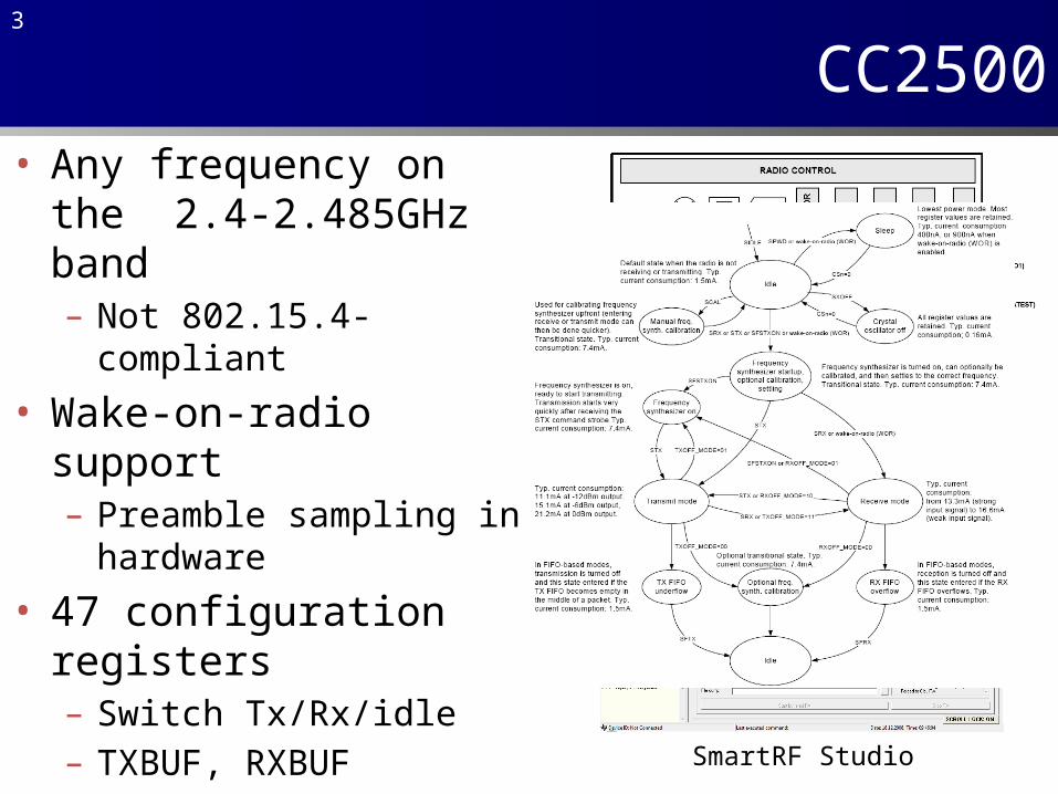
CC2500• Any frequency on the 2.4-
2.485GHz band– Not 802.15.4-compliant
• Wake-on-radio support– Preamble sampling in
hardware
• 47 configuration registers– Switch Tx/Rx/idle– TXBUF, RXBUF– Tx power and frequency
• Follows a state machineSmartRF Studio

4
Interconnection
4
Chip Select
Clock
SPI interfaceinterrupts

5
eZ430-RF2500
2 LEDspushbutton
CC2500
chip antenna
26MHz crystal
for radio
extension ports
MSP430
USB programmer:• Power• Debug (JTAG) • Interface (serial)
6
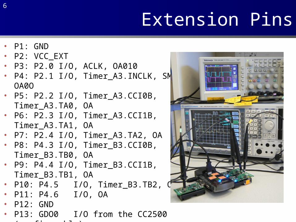
Extension Pins• P1: GND• P2: VCC_EXT• P3: P2.0 I/O, ACLK, OA010• P4: P2.1 I/O, Timer_A3.INCLK, SMCLK, OA0O• P5: P2.2 I/O, Timer_A3.CCI0B, Timer_A3.TA0, OA• P6: P2.3 I/O, Timer_A3.CCI1B, Timer_A3.TA1, OA• P7: P2.4 I/O, Timer_A3.TA2, OA• P8: P4.3 I/O, Timer_B3.CCI0B, Timer_B3.TB0, OA• P9: P4.4 I/O, Timer_B3.CCI1B, Timer_B3.TB1, OA• P10: P4.5 I/O, Timer_B3.TB2, OA• P11: P4.6 I/O, OA• P12: GND• P13: GDO0 I/O from the CC2500 (configurable)• P14: GDO2 I/O from the CC2500 (configurable)• P15: P3.2 I/O, UC1SOMI• P16: P3.3 I/O, UC1CLK• P17: P3.0 I/O• P18: P3.1 I/O, UC1SIMO
7
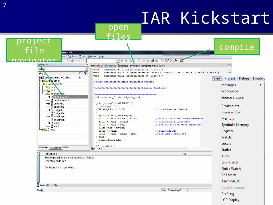
IAR Kickstartproject file navigator
compile
open files

8
Talking with your mote over “USB”
• Use Windows Device Manager to idenfify the COM port the eZ430-RF2500 is on
• Use PuTTY to connect to that port

9
Operations on binary data
• A = 0b01101001• ~A = 0b10010110• A |= 0b00000010 => A=0b01101011• A &=~0b00001000 => A=0b01100001• A ^= 0b10001000 => A=0b11100001• A<<2 => A=0b10100100• A>>2 => A=0b00011010
10
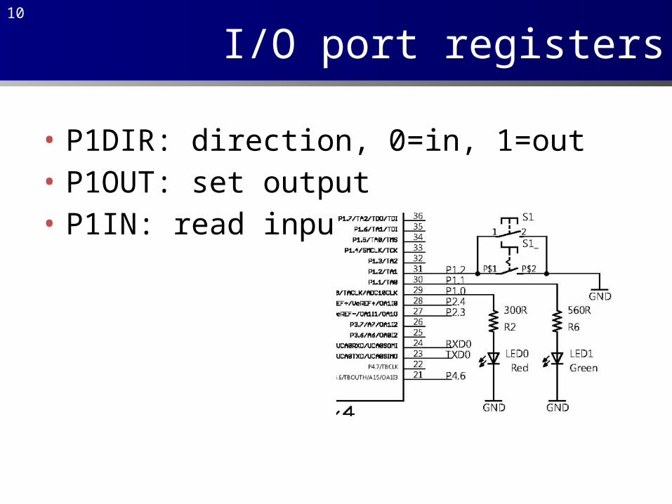
I/O port registers
• P1DIR: direction, 0=in, 1=out• P1OUT: set output• P1IN: read input

11
A steady LED
led_steady
Disable watchdog
timer
P1.0 and P1.1 as output
P1.0=1 and P1.1=1
Continue executing
#include "io430.h"#include "in430.h"int main( void ){ WDTCTL = WDTPW + WDTHOLD; P1DIR |= 0x03; P1OUT |= 0x03; while(1);}
12
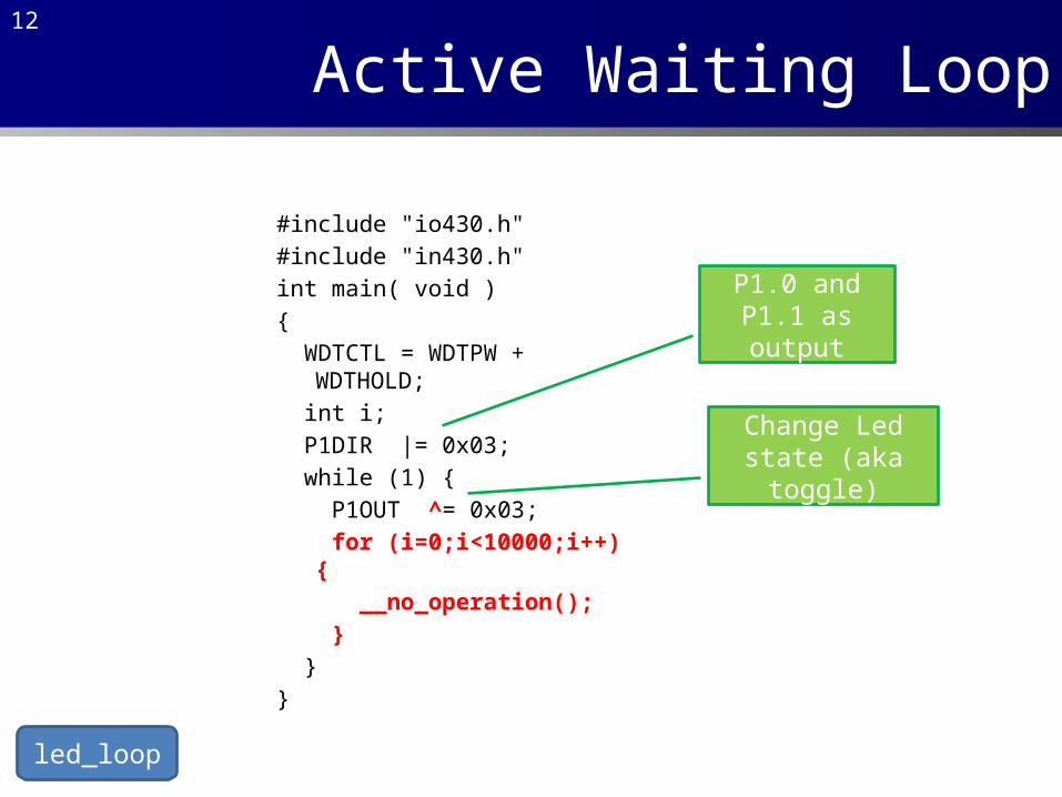
Active Waiting Loop
led_loop
#include "io430.h"#include "in430.h"int main( void ){ WDTCTL = WDTPW + WDTHOLD; int i; P1DIR |= 0x03; while (1) { P1OUT ^= 0x03; for (i=0;i<10000;i++) { __no_operation(); } }}
P1.0 and P1.1 as output
Change Led state (aka toggle)
13
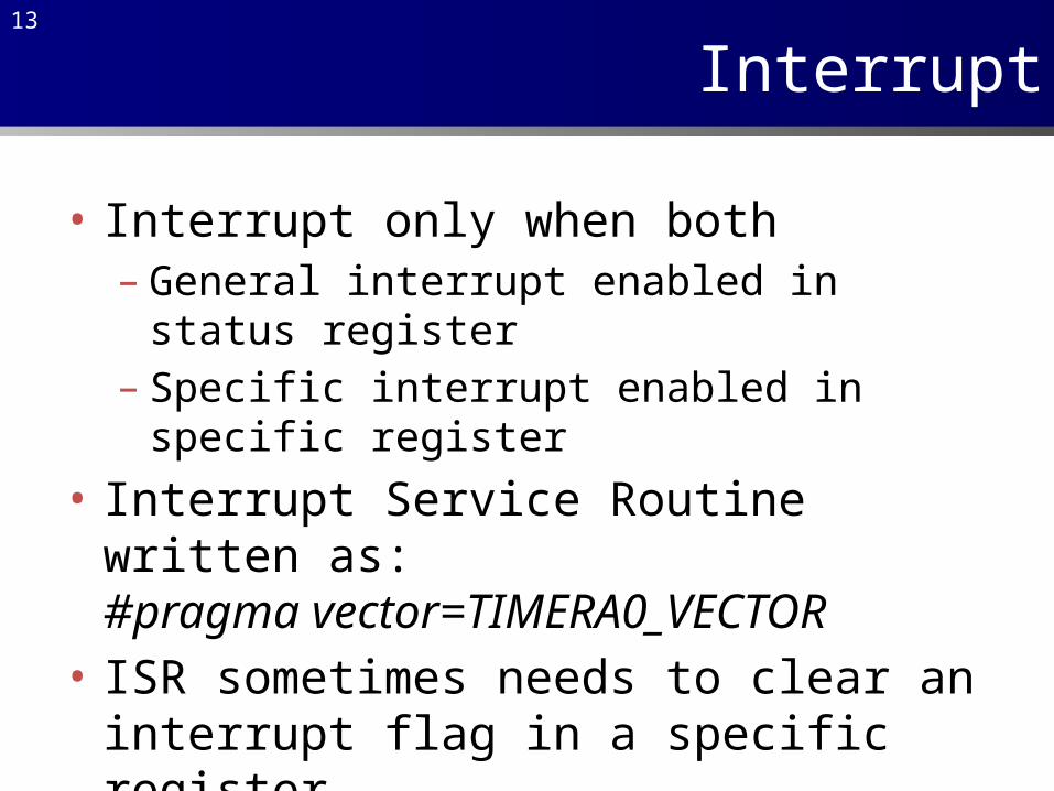
Interrupt
• Interrupt only when both– General interrupt enabled in status register– Specific interrupt enabled in specific register
• Interrupt Service Routine written as:#pragma vector=TIMERA0_VECTOR
• ISR sometimes needs to clear an interrupt flag in a specific register
14
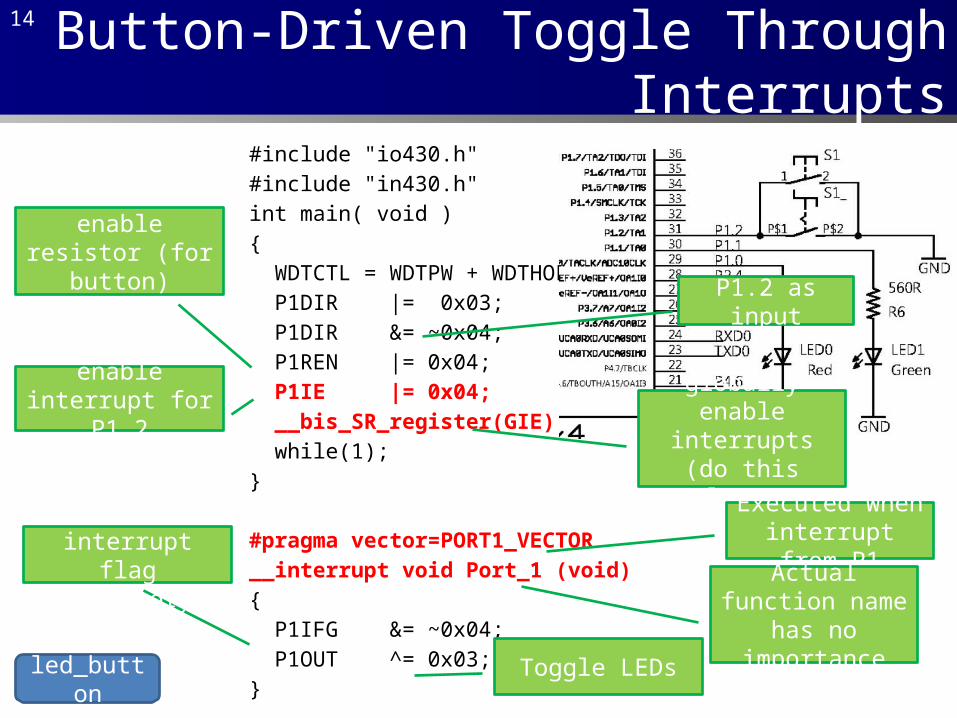
Button-Driven Toggle Through Interrupts
led_button
#include "io430.h"#include "in430.h"int main( void ){ WDTCTL = WDTPW + WDTHOLD; P1DIR |= 0x03; P1DIR &= ~0x04; P1REN |= 0x04; P1IE |= 0x04; __bis_SR_register(GIE); while(1);}
#pragma vector=PORT1_VECTOR__interrupt void Port_1 (void){ P1IFG &= ~0x04; P1OUT ^= 0x03;}
P1.2 as input
enable resistor (for button)
enable interrupt for P1.2 globally enable
interrupts (do this last)
Executed when interrupt from P1
Actual function name has no importance
Clear interrupt flag (mandatory)
Toggle LEDs

15
Timer
• A timer is a counter which– Counts in a certain way (up, down, continuous)– At every clock tick
• Can be used in two ways:– Triggers interrupts when reaching a given value
(compare mode)or– Records its timer value on other interrupts
(capture mode)
16
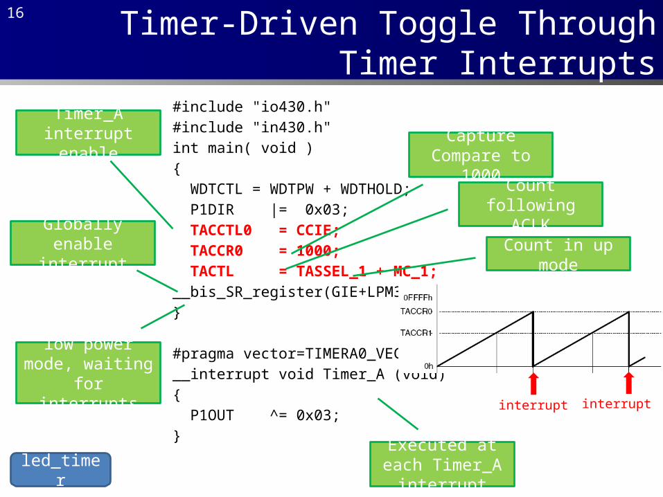
Timer-Driven Toggle Through Timer Interrupts
led_timer
#include "io430.h"#include "in430.h"int main( void ){ WDTCTL = WDTPW + WDTHOLD; P1DIR |= 0x03; TACCTL0 = CCIE; TACCR0 = 1000; TACTL = TASSEL_1 + MC_1;__bis_SR_register(GIE+LPM3_bits);}
#pragma vector=TIMERA0_VECTOR__interrupt void Timer_A (void){ P1OUT ^= 0x03;}
Timer_A interrupt enable Capture Compare
to 1000
Count following ACLK
Count in up mode
interrupt interrupt
Globally enable interrupt
low power mode, waiting for interrupts
Executed at each Timer_A interrupt