lab 1: engineering drawing, 3d printing and laser … patterns. …and ... view and hidden line...
TRANSCRIPT

Lab 1: Engineering Drawing, 3D Printing and Laser Cutting Innovation Fellows Program Bootcamp
Prof. Steven S. Saliterman
In the following exercises you will learn basic drawing skills required for most projects you will encounter. Exploring SolidWorks tools beyond those covered here and drawing other objects that come to mind will improve your abilities. The three exercises include making 3D FDM printed parts in plastic, allowing an immediate feedback of your work. You will also learn about sheet metal layout, making assemblies, and if you have time, advanced dimen-sioning techniques. Print this lab as the first of a series of labs that you will assemble into a 3-ring binder as your “Lab Workbook.” Save your SolidWorks part and drawing files, including JPEGS of each. Print them and attach to the end of this lab in your workbook. If able, take some photos of your 3D parts to attach. You may scale these down to decrease print time, but not so much as to reduce the quality. Exercise 1-1: Your First SolidWorks Drawing Objective: Familiarization with creating the following part features:
1. Sketches such as circles, lines and offsets. 2. Selecting a plane or surface for sketches. 3. Dimensioning. 4. Features such as extruded-boss and extruded cut.\. 5. Various views (perspectives), fill, and wire frame models. 6. Fillets 7. Temporary axis. 8. Circular patterns.
…and drawing tasks:
1. View and hidden line removal. 2. Section and detail views. 3. Adding isometric view with filled surfaces. 4. Center lines and center marks. 5. Dimensioning and adding text.
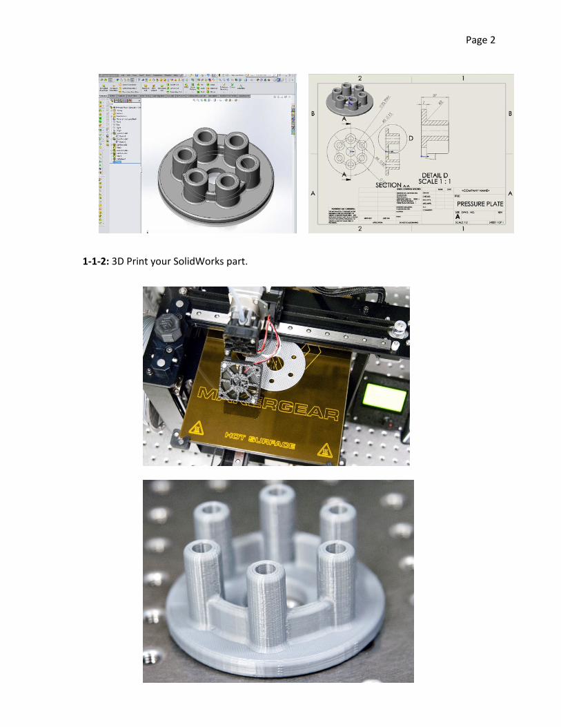
1-1-1: Launch SolidWorks - Select “Resources” to open the Task Pane, select Tutorials and complete the “Getting Started” tutorial.
Page 2
1-1-2: 3D Print your SolidWorks part.

Page 3
Exercise 2: Open revolves and Sweeps Objectives: Familiarization with the following:
1. Sketching a revolve profile with lines, arcs, dimensioning, and trimming. 2. Adding dimensional relationships. 3. Creating a revolve. 4. Creating a sweep path and coincidental relationship. 5. Sweeping along the path. 6. Making an extruded-cut with draft. 7. Making a transparent view to see the cuts. 8. Making a Real View appearance.
1-2-1: Launch SolidWorks - Select “Resources” to open the Task Pane, select Tutorials and complete the “Revolves and Sweeps” tutorial. 1-2-2: 3D Print your SolidWorks part.
Page 4
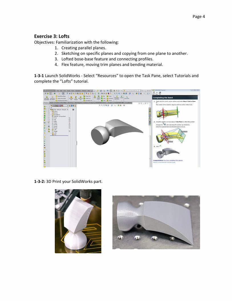
Exercise 3: Lofts Objectives: Familiarization with the following:
1. Creating parallel planes. 2. Sketching on specific planes and copying from one plane to another. 3. Lofted bose-base feature and connecting profiles. 4. Flex feature, moving trim planes and bending material.
1-3-1 Launch SolidWorks - Select “Resources” to open the Task Pane, select Tutorials and complete the “Lofts” tutorial. 1-3-2: 3D Print your SolidWorks part.
Page 5
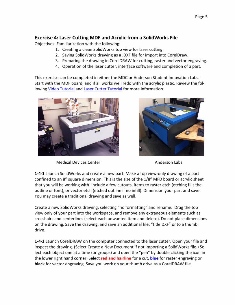
Exercise 4: Laser Cutting MDF and Acrylic from a SolidWorks File Objectives: Familiarization with the following:
1. Creating a clean SolidWorks top view for laser cutting. 2. Saving SolidWorks drawing as a .DXF file for import into CorelDraw. 3. Preparing the drawing in CorelDRAW for cutting, raster and vector engraving. 4. Operation of the laser cutter, interface software and completion of a part.
This exercise can be completed in either the MDC or Anderson Student Innovation Labs. Start with the MDF board, and if all works well redo with the acrylic plastic. Review the fol-lowing Video Tutorial and Laser Cutter Tutorial for more information. 1-4-1 Launch SolidWorks and create a new part. Make a top view-only drawing of a part confined to an 8” square dimension. This is the size of the 1/8” MFD board or acrylic sheet that you will be working with. Include a few cutouts, items to raster etch (etching fills the outline or font), or vector etch (etched outline if no infill). Dimension your part and save. You may create a traditional drawing and save as well. Create a new SolidWorks drawing, selecting “no formatting” and rename. Drag the top view only of your part into the workspace, and remove any extraneous elements such as crosshairs and centerlines (select each unwanted item and delete). Do not place dimensions on the drawing. Save the drawing, and save an additional file: “title.DXF” onto a thumb drive. 1-4-2 Launch CorelDRAW on the computer connected to the laser cutter. Open your file and inspect the drawing. (Select Create a New Document if not importing a SolidWorks file.) Se-lect each object one at a time (or groups) and open the “pen” by double clicking the icon in the lower right hand corner. Select red and hairline for a cut, blue for raster engraving or black for vector engraving. Save you work on your thumb drive as a CorelDRAW file.
Medical Devices Center Anderson Labs

Page 6
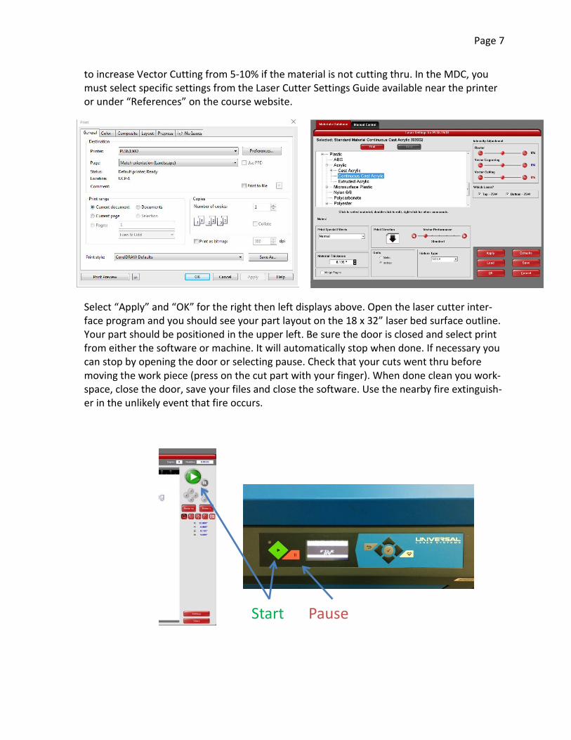
Check that the vent is on. Place your 8” square x 1/8th thick stock into the laser cutter upper left hand corner, and “focus” by setting the Z-height (upper and lower bed) with the gage: When ready to print select “Print” from the CorelDRAW “File” menu and in the following dialog select “Preferences.” The display is different in Anderson Labs vs. the MDC. In Ander-son Labs, Select Medium Density Fiberboard (MDF) or Continuous Cast Acrylic depending on the material you are using. Add .01-.02” to the actual material thickness. You may also need
Page 7
Start Pause
to increase Vector Cutting from 5-10% if the material is not cutting thru. In the MDC, you must select specific settings from the Laser Cutter Settings Guide available near the printer or under “References” on the course website. Select “Apply” and “OK” for the right then left displays above. Open the laser cutter inter-face program and you should see your part layout on the 18 x 32” laser bed surface outline. Your part should be positioned in the upper left. Be sure the door is closed and select print from either the software or machine. It will automatically stop when done. If necessary you can stop by opening the door or selecting pause. Check that your cuts went thru before moving the work piece (press on the cut part with your finger). When done clean you work-space, close the door, save your files and close the software. Use the nearby fire extinguish-er in the unlikely event that fire occurs.

Page 8
Exercise 5: Sketch Blocks (Optional) Objectives: Familiarization with the following:
1. Making blocks. 2. Making relationships between blocks. 3. Demonstrating movement. 4. Saving, inserting, editing and renaming blocks. 5. Testing motion about coincident and colinear relationships. 6. Combining blocks as a new block. 7. Linking blocks with relationships.
1-5-1 Launch SolidWorks - Select “Resources” to open the Task Pane, select Tutorials and complete the “Sketch Blocks” tutorial.
End of Engineering Drawing, 3D Printing and Laser Cutting