l7-s1 uc diagrams 2003 sjsu -- cmpe advanced object-oriented analysis & design dr. m.e. fayad,...
TRANSCRIPT

2003 SJSU -- CmpE L7-S1 UC Diagrams
Advanced Object-Oriented Analysis & Design
Dr. M.E. Fayad, Professor
Computer Engineering Department, Room #283I
College of Engineering
San José State University
One Washington Square
San José, CA 95192-0180
http://www.engr.sjsu.edu/~fayad
2003 SJSU – CmpE --- M.E. Fayad L7-S2 UC Diagrams
2
Lesson 7:Use Case Diagrams
2003 SJSU – CmpE --- M.E. Fayad L7-S3 UC Diagrams
Lesson Objectives
Objectives
3
Overview of Previous Lecture Use Case Models and Diagrams Notation
Discuss the following:
– What is use case modeling?
– Use Case Modeling -- Core concepts
– Use Case Diagram tour
– When to model use cases
– Use Case Modeling tips
– Use Case Templates
– Examples: Library & University Registration

2003 SJSU – CmpE --- M.E. Fayad L7-S4 UC Diagrams
Use Case Modeling: Core ElementsUse Case Modeling: Core Elements
4
Construct Description Syntax
use case A sequence of actions, including variants, that a system (or other entity) can perform, interacting with actors of the system.
actor A coherent set of roles that users of use cases play when interacting with these use cases.
system boundary
Represents the boundary between the physical system and the actors who interact with the physical system.
UseCaseNam e
ActorNam e

2003 SJSU – CmpE --- M.E. Fayad L7-S5 UC Diagrams
Use Case Modeling: Core Relationships Use Case Modeling: Core Relationships (1)Construct Description Syntax
association The participation of an actor in a usecase. i.e., instance of an actor andinstances of a use case communicatewith each other.
extend A relationship from an extension usecase to a base use case, specifyinghow the behavior for the extensionuse case can be inserted into thebehavior defined for the base usecase.
generalization A taxonomic relationship between amore general use case and a morespecific use case.
5
<<extend>>

2003 SJSU – CmpE --- M.E. Fayad L7-S6 UC Diagrams
Use Case Modeling: Core Relationships Use Case Modeling: Core Relationships (2)
6
Construct Description Syntax
include An relationship from a base use caseto an inclusion use case, specifyinghow the behavior for the inclusion usecase is inserted into the behaviordefined for the base use case.
<<include>>
Multiplicities are missing!

2003 SJSU – CmpE --- M.E. Fayad L7-S7 UC Diagrams
Shows use cases, actor and their relationships
Use case internals can be specified by text and/or interaction diagrams
Kinds–use case diagram–use case description
7
Use Case Diagram Tour

2003 SJSU – CmpE --- M.E. Fayad L7-S8 UC Diagrams
Model user requirements with use cases. Model test scenarios with use cases. If you are using a use-case driven method
– start with use cases and derive your structural and behavioral models from it.
If you are not using a use-case driven method– make sure that your use cases are consistent
with your structural and behavioral models
8
When to model use cases

2003 SJSU – CmpE --- M.E. Fayad L7-S9 UC Diagrams
Make sure that each use case describes a significant chunk of system usage that is understandable by both domain experts and programmers
When defining use cases in text, use nouns and verbs accurately and consistently to help derive objects and messages for interaction diagrams
Factor out common usages that are required by multiple use cases– If the usage is required use <<include>>– If the base use case is complete and the usage may be
optional, consider use <<extend>> A use case diagram should
– contain only use cases at the same level of abstraction– include only actors who are required
Large numbers of use cases should be organized into packages 9
Use Case Modeling Tips

2003 SJSU – CmpE --- M.E. Fayad L7-S10 UC Diagrams
10
Actors (1)
An actor is someone or some thing that must interact with the system under development
StudentRegistrar Professor Billing System

2003 SJSU – CmpE --- M.E. Fayad L7-S11 UC Diagrams
An actor represents a coherent set of
roles that users of use cases play when
interacting with the use cases
Typically, an actor represents a role that
a human, a hardware device, or even
another system plays with a system 11
Actors (2)
2003 SJSU – CmpE --- M.E. Fayad L7-S12 UC Diagrams
A use case is a pattern of behavior the
system exhibits
– Each use case is a sequence of related
transactions performed by an actor and the
system in a dialogue
– It describes what a system does but NOT
how it does it 12
Use Cases (1)

2003 SJSU – CmpE --- M.E. Fayad L7-S13 UC Diagrams
A use case is a description of a set of
sequences of actions, including variants, that
a system performs to yield an observable
result of value to an actor
Each use case must have a name that
distinguishes it from other use cases 13
Use Cases (2)

2003 SJSU – CmpE --- M.E. Fayad L7-S14 UC Diagrams
Actors are examined to determine their needs
– Registrar -- maintain the curriculum
– Professor -- request roster
– Student -- maintain schedule
14
Use Cases (3)
Maintain ScheduleMaintain Curriculum Request Course Roster
2003 SJSU – CmpE --- M.E. Fayad L7-S15 UC Diagrams
Can organize use cases by specifying
relationships among them.
– Generalization
– Include
– Extend
15
Use Case Relationships (1)

2003 SJSU – CmpE --- M.E. Fayad L7-S16 UC Diagrams
Generalization
– Child use case inherits the behavior and
meaning of the parent use case
– Child use case may add to or override the
behavior of its parent
– Child use case may be substituted any
place the parent use case appears 16
Use Case Relationships (2)

2003 SJSU – CmpE --- M.E. Fayad L7-S17 UC Diagrams
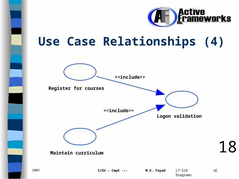
Include
– Base use case explicitly incorporates the behavior
of another use case at a location specified in the
base
– Use an include relationship to avoid describing the
same flow of events several times
• by putting the common behavior in a use case of its
own
17
Use Case Relationships (3)
2003 SJSU – CmpE --- M.E. Fayad L7-S18 UC Diagrams
18
Use Case Relationships (4)
Register for courses
<<include>>
Logon validation<<include>>
Maintain curriculum

2003 SJSU – CmpE --- M.E. Fayad L7-S19 UC Diagrams
Extend– An extend relationship between use cases means
that the base use case implicitly incorporates the behavior of another use case at a location specified indirectly by the extending use case
– Use an extend relationship to model the part of a use case the user may see as optional system behavior
19
Use Case Relationships (5)

2003 SJSU – CmpE --- M.E. Fayad L7-S20 UC Diagrams
20
Use Case Relationships (6)
SuperUse Case
IncludedUse Case
ExtendingUse CaseSub
Use Case
<<include>>
<<extend>>generalization

2003 SJSU – CmpE --- M.E. Fayad L7-S21 UC Diagrams
Fig. 3-45, UML Notation Guide
Use Case Relationships (7)
additional requests :
OrderProduct
SupplyArrange
«include»«include»«include»
RequestCatalog
«extend»Extension points
PaymentCustomer Data
after creation of the order
Place Order
1 * the salesperson asks forthe catalog

2003 SJSU – CmpE --- M.E. Fayad L7-S22 UC Diagrams
Fig. 3-46, UML Notation Guide
Use Case Relationships (8)
EstablishCredit
PlaceOrder
Salesperson
Supervisor
1 *
1 *
22
X

2003 SJSU – CmpE --- M.E. Fayad L7-S23 UC Diagrams
23
Use Case Model UC model =
Use Cases + System Boundary + Actors (outside the system boundary)

2003 SJSU – CmpE --- M.E. Fayad L7-S24 UC Diagrams
24
What is use case modeling?
use case model: a view of a system that emphasizes the behavior as it appears to outside users. A use case model partitions system functionality into transactions (‘use cases’) that are meaningful to users (‘actors’).

2003 SJSU – CmpE --- M.E. Fayad L7-S25 UC Diagrams
Use case diagrams are created to visualize the relationships between actors and use cases
25
Use Case Diagram (1)
Student
Registrar
Professor
Maintain Schedule
Maintain Curriculum
Request Course Roster
Billing System

2003 SJSU – CmpE --- M.E. Fayad L7-S26 UC Diagrams
A use case diagram is a diagram that shows a
set of use cases and actors and their
relationships.
Commonly contain– Use cases
– Actors
– Dependency, generalization, and association
relationships 26
Use Case Diagram (2)

2003 SJSU – CmpE --- M.E. Fayad L7-S27 UC Diagrams
27
Use Case Diagram (3)

2003 SJSU – CmpE --- M.E. Fayad L7-S28 UC Diagrams
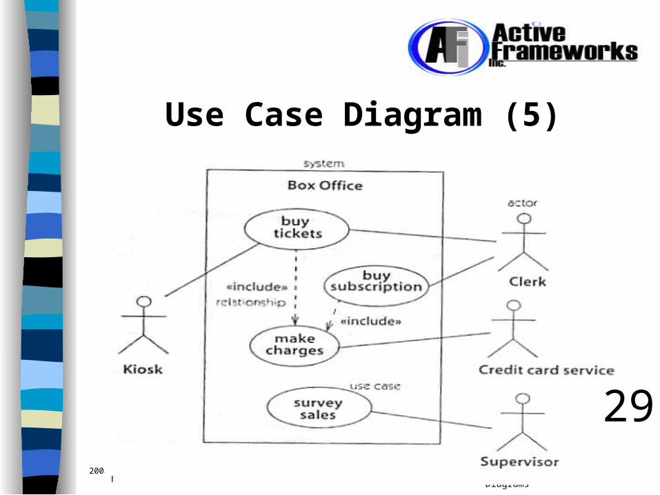
28
Use Case Diagram (4)
2003 SJSU – CmpE --- M.E. Fayad L7-S29 UC Diagrams
Use Case Diagram (5)
29

2003 SJSU – CmpE --- M.E. Fayad L7-S30 UC Diagrams
Use Case Diagram (6)
30
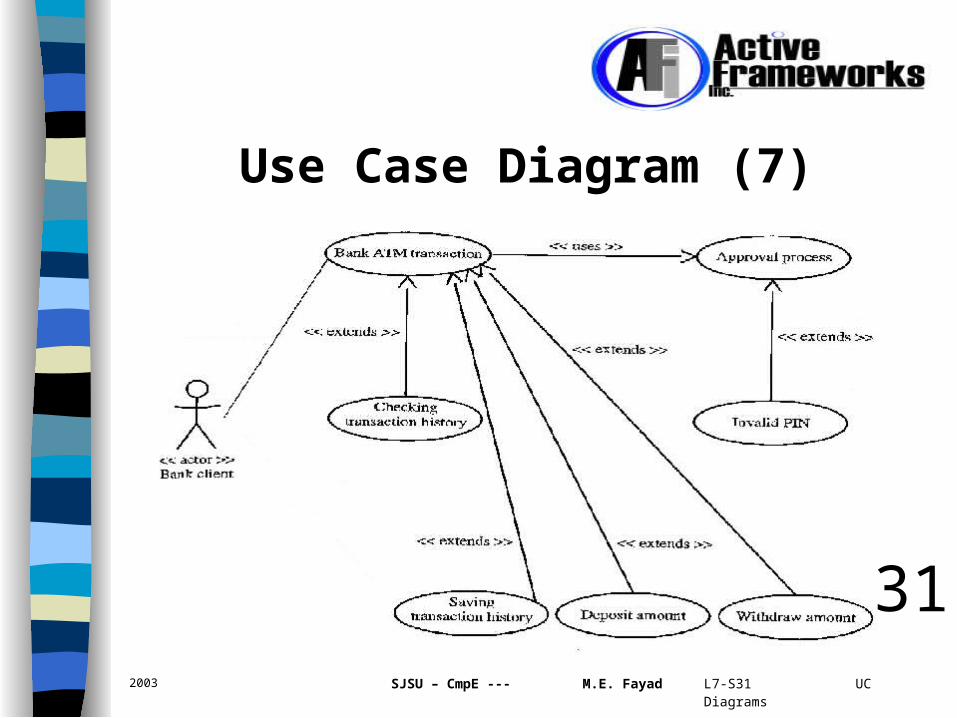
2003 SJSU – CmpE --- M.E. Fayad L7-S31 UC Diagrams
Use Case Diagram (7)
31

2003 SJSU – CmpE --- M.E. Fayad L7-S32 UC Diagrams
Use Case Diagram (7)
32

2003 SJSU – CmpE --- M.E. Fayad L7-S33 UC Diagrams
Use Case Diagram (8)
33

2003 SJSU – CmpE --- M.E. Fayad L7-S34 UC Diagrams
The Use Case Model
We must now identify the users of the system and the tasks they must undertake with the system. The details of the use case should be documented, using a Use Case Template.
There are many different use case templates Show a few!!
34

2003 SJSU – CmpE --- M.E. Fayad L7-S35 UC Diagrams
Use Case Template & Example: Change Flight Use Case #: 1.0 Use Case Name: Change flight Actors: traveler, client account db, airline reservation system Preconditions:
Traveler has logged on to the system and selected ‘change flight itinerary’ option
Basic course System retrieves traveler’s account and flight itinerary from client account database System asks traveler to select itinerary segment she wants to change; traveler selects itinerary segment. System asks traveler for new departure and destination information; traveler provides information. If flights are available then … System displays transaction summary.
Alternative courses If no flights are available then …
35

2003 SJSU – CmpE --- M.E. Fayad L7-S36 UC Diagrams
My Use Case Template
Use Case TemplatePACKAGE: _________________ [Description (an over view of the package)].USE CASES: [A package will have one or more Use Cases].Use Case No.: [1.1]Use Case Title: [A descriptive title]
[Ex. adding a new patient, or adding a new role].Actors: _______, _______, _______, _______.
[Any users of the Use Case, ex. human, machine, other systems or subsystems].Corresponding Roles: _______, _______, _______, _______.
[There is a different role per actor in every Use Case].Classes: _______, _______, _______, _______.
[List all the classes within the Use Case Description].Corresponding Attributes and Behaviors: Enduring Business Themes (EBT): _______, _______, _______Business Objects (BO): _______, _______, _______, _______.Industrial Objects (IO): _______, _______, _______, _______.
[This represents a clear classification of all the classes within the use case description].
Description of the Use Case:[Describes the data flow and the logic flow of the Use Case].
Alternatives:
36

2003 SJSU – CmpE --- M.E. Fayad L7-S37 UC Diagrams
Case Study 1: Library System
You have been contracted to develop a computer system for a university library. The library currently uses a 1960s program, written in an obsolete language, for some simple bookkeeping tasks, and a card index, for user browsing. You are asked to build an interactive system which handles both of these aspects online.*
*Example from: “Using UML”, by: Pooley and Stevens
37

2003 SJSU – CmpE --- M.E. Fayad L7-S38 UC Diagrams
First Step!
Time to start gathering the user requirements.– Different users will have different, sometimes
conflicting priorities– Users will not, necessarily know what they
want– It is very possible to miss something vital– The managers do not always know what the
users have to do– Users can be, and frequently are, hostile.
Why? What can be done about it? 38

2003 SJSU – CmpE --- M.E. Fayad L7-S39 UC DiagramsCopyright © 1997 by Rational Software Corporation
Documenting Use Cases
A flow of events description is created for each use case– Written from an actors point of view
Details what the system must provide to the actor when the use case is executed
Typical contents– How the use case starts and ends– Normal flow of events– Alternate flow of events– Exceptional flow of events
39
2003 SJSU – CmpE --- M.E. Fayad L7-S40 UC Diagrams
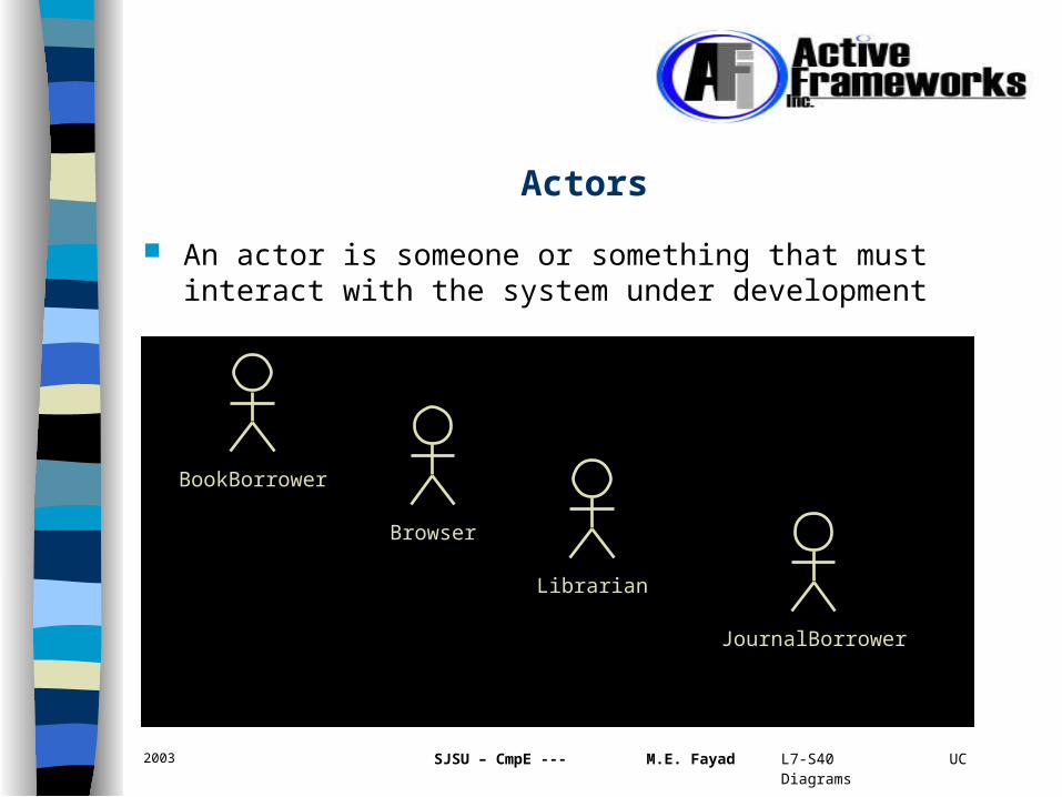
Actors
An actor is someone or something that must interact with the system under development
BookBorrower
Browser
Librarian
JournalBorrower

2003 SJSU – CmpE --- M.E. Fayad L7-S41 UC Diagrams
Use CasesActors are examined to determine their needs
– BookBorrower• Checkout and return books
– Browser• locate and peruse items of interest
– Librarian• maintain order and accountablility
– JournalBorrower• checkout and return journals
Checkout JournalCheckout Book Return Book

2003 SJSU – CmpE --- M.E. Fayad L7-S42 UC Diagrams
Use Case Description
The usual course through the system when actor is using the system is called the basic course. Other courses would be modeled as extending Use Cases.
An example of a basic course would be: – Borrow copy of book A BookBorrower presents a book. The
system checks that the potential borrower is a member of the library, and that s/he does not already have the maximum permitted number of books on loan. This maximum is six unless the member is a staff member, in which case it is 12. If both checks succeed, the system records that this library member has this copy of the book on loan.
**Example from: “Using UML”, by: Pooley and Stevens 42

2003 SJSU – CmpE --- M.E. Fayad L7-S43 UC Diagrams
Use Case Diagram for the first iteration
*Example from: “Using UML”, by: Pooley and Stevens
43

2003 SJSU – CmpE --- M.E. Fayad L7-S44 UC Diagrams
What Requirements would an ideal system satisfy?
Books and Journals: The library contains books and journals. It may have several copies of a given book. Some of the books are for short term loans only. All other books may be borrowed by any library member for three weeks. Only members of staff may borrow journals. Members of the library can normally borrow up to six items at a time, but members of staff may borrow up to 12 items at one time. New books and journals arrive regularly, and are sometimes disposed of. The current year’s journals are sent away to be bound into volumes at the end of each year.*
*Example from: “Using UML”, by: Pooley and Stevens
44
2003 SJSU – CmpE --- M.E. Fayad L7-S45 UC Diagrams
What Requirements would an ideal system satisfy?
Borrowing: It is essential that the system keep track of when books and journals are borrowed and returned, since the current system already does that. The new system should produce reminders when a book is overdue. There may in future be a requirement for users to be able to extend the loan of a book if it is not reserved.
Browsing: The system should allow users to search for a book on a particular topic, by a particular author, etc., to check whether a copy of the book is available for loan, and if not, to reserve the book. Anyone can browse in the library.*
*Example from: “Using UML”, by: Pooley and Stevens
45

2003 SJSU – CmpE --- M.E. Fayad L7-S46 UC Diagrams
Use Cases for the library
*Example from: “Using UML”, by: Pooley and Stevens
46

2003 SJSU – CmpE --- M.E. Fayad L7-S47 UC Diagrams
Case Study 2: University Registration
The ESU University wants to computerize their registration system– The Registrar sets up the curriculum for a semester
• One course may have multiple course offerings– Students select 4 primary courses and 2 alternate courses– Once a student registers for a semester, the billing system is
notified so the student may be billed for the semester– Students may use the system to add/drop courses for a period of
time after registration– Professors use the system to receive their course offering rosters– Users of the registration system are assigned passwords which
are used at logon validation 47

2003 SJSU – CmpE --- M.E. Fayad L7-S48 UC DiagramsCopyright © 1997 by Rational Software Corporation
Actors
Student
Registrar
Professor
Billing System
48

2003 SJSU – CmpE --- M.E. Fayad L7-S49 UC DiagramsCopyright © 1997 by Rational Software Corporation
Use Cases
Actors are examined to determine their needs– Registrar
• maintain the curriculum
– Professor • request roster
– Student • maintain schedule
– Billing System • receive billing information from registration
Maintain ScheduleMaintain Curriculum Request Course Roster

2003 SJSU – CmpE --- M.E. Fayad L7-S50 UC DiagramsCopyright © 1997 by Rational Software Corporation
Maintain Curriculum: Flow of Events (description)
This use case begins when the Registrar logs onto the Registration System and enters his/her password. The system verifies that the password is valid (E-1) and prompts the Registrar to select the current semester or a future semester (E-2). The Registrar enters the desired semester. The system prompts the professor to select the desired activity: ADD, DELETE, REVIEW, or QUIT.
If the activity selected is ADD, the S-1: Add a Course subflow is performed.
If the activity selected is DELETE, the S-2: Delete a Course subflow is performed.
If the activity selected is REVIEW, the S-3: Review Curriculum subflow is performed.
If the activity selected is QUIT, the use case ends. 50

2003 SJSU – CmpE --- M.E. Fayad L7-S51 UC DiagramsCopyright © 1997 by Rational Software Corporation
Use Case Model Use case diagrams are created to visualize the relationships
between actors and use cases
Student
Registrar
Professor
Maintain Schedule
Maintain Curriculum
Request Course Roster
Billing System

2003 SJSU – CmpE --- M.E. Fayad L7-S52 UC DiagramsCopyright © 1997 by Rational Software Corporation
Uses and Extends Use Case Relationships
As the use cases are documented, other use case relationships may be discovered
– A uses relationship shows behavior that is common to one or more use cases
– An extends relationship shows optional behavior
Register for courses
<<uses>>
Logon validation<<uses>>
Maintain curriculum

2003 SJSU – CmpE --- M.E. Fayad L7-S53 UC Diagrams
Possible Problems with Use Cases
1. Use Cases emphasize ordering. This can be considered to be incompatible with object technology.
2. Over modeling – Leads to requirement inflation.
53
2003 SJSU – CmpE --- M.E. Fayad L7-S54 UC Diagrams
Cautions
Do not invent requirements!– Use cases are about the user’s requirements,
not about what you, as the designer might think that the system could usefully do!
54

2003 SJSU – CmpE --- M.E. Fayad L7-S55 UC Diagrams
Use Case No.: 1.1.1 Use Case Title: Find Candidate Actors: Registrar Roles: Data Entry Clerk (Registrar), Classes: IDSession, PersonProfile, PersonIdentifier,
PersonTraits , CandidateListGenerator, DataManager Enduring Business Themes: (EBT): identity, security, Business Objects: IDSession, IDManager, DataManager,
PersonIdentifier Industrial Objects: CandidateList, PersonTraits, PersonProfiles,
SecurityManager, TraitGatekeeper
55
Sample Use Case from Philips Project (1)

2003 SJSU – CmpE --- M.E. Fayad L7-S56 UC Diagrams
Description of the Use Case: 1. The Registrar enters the information about a person into the
System. 2. IDSession clears the request with Security. 3. The System tells the Person-Identifier to search for candidates. 4. The Person-Identifier gives the request to its DataManager 5. The DataManager determines a list of candidates, using its
CandidateListGenerator and its set of PersonProfiles and returns it to the System.
6. The Registrar chooses the candidate from the list that represents the person.
56
Sample Use Case from Philips Project (2)

2003 SJSU – CmpE --- M.E. Fayad L7-S57 UC Diagrams
Use Case No.: 1.2.1 Use Case Title: Register New ID Actors: Registrar Roles: Data Entry Clerk (Registrar), Classes: IDSession, IDManager, PersonProfile, PersonTraits,
CandidateList, PersonIdentifier Enduring Business Themes (EBT): identity, security Business Objects (BO): IDSession, IDManager, PersonIdentifier
Industrial Objects (IO): PersonProfile, PersonTraits, CandidateList
57
Sample Use Case from Philips Project (3)

2003 SJSU – CmpE --- M.E. Fayad L7-S58 UC Diagrams
Description of the Use Case: 1. The Registrar enters the information about a person into the IDSession. 2. The IDSession has security clear the request. 3. The IDSession has the PersonIdentifier search for candidates. 4. The Person-Identifier determines that no candidates fit the criteria. 5. The Person-Identifier gives this information to the system. 6. The informs the Registrar that no candidates exist. 7. System asks the Registrar if the person should be added as new. 8. Registrar tells System to add new person. 9. System sends traits to ID-Manager. 10. ID-Manager creates a new profile.
58
Sample Use Case from Philips Project (4)
2003 SJSU – CmpE --- M.E. Fayad L7-S59 UC Diagrams
Exceptional Flow of Events 01: If any of the identifying information entered by the Registrar is incomplete or invalid the system displays corresponding error message(s). The system will not validate the New Person until all identifying information is made available.
Exceptional Flow of Events 02: In case the system determines that one or more of the identifying information for a person matches one or more person(s) already in the system the Registrar is displayed with a screen listing all the person(s) meeting the search criteria. The Registrar is then given the opportunity to either create the person in the system with a new ID or pick one from the selection list.
59
Sample Use Case from Philips Project (5)
2003 SJSU – CmpE --- M.E. Fayad L7-S60 UC Diagrams
Use Case No.: 1.3.1
Use Case Title: Get Patient Profile using Patient ID
Actors / Roles: Nurse, Patient, and Profile Access
Classes:
Enduring Business Themes (EBT): Diagnosis, Customer Service and Complete Medical History
Business Objects (BO): Profile Access, Identify Person and Identity
Industrial Objects (IO): Identity Access
60
Sample Use Case from Philips Project (6)
2003 SJSU – CmpE --- M.E. Fayad L7-S61 UC Diagrams
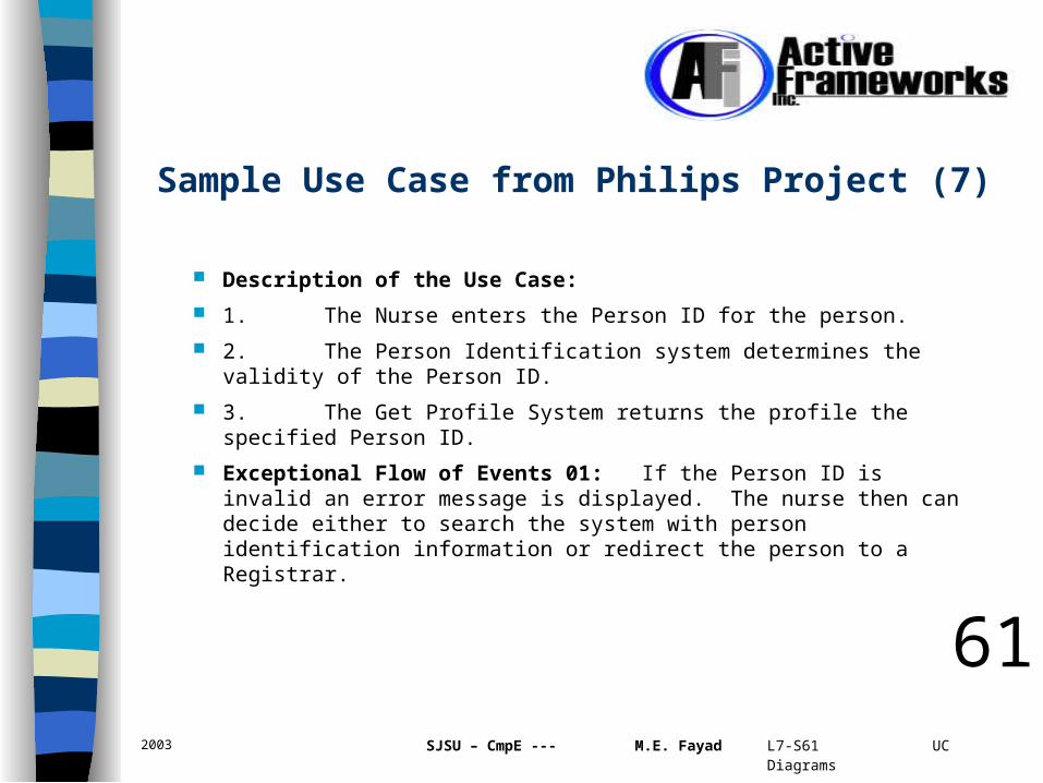
Description of the Use Case:
1. The Nurse enters the Person ID for the person.
2. The Person Identification system determines the validity of the Person ID.
3. The Get Profile System returns the profile the specified Person ID.
Exceptional Flow of Events 01: If the Person ID is invalid an error message is displayed. The nurse then can decide either to search the system with person identification information or redirect the person to a Registrar.
61
Sample Use Case from Philips Project (7)

2003 SJSU – CmpE --- M.E. Fayad L7-S62 UC Diagrams
Summary & Simplifications
62
2003 SJSU – CmpE --- M.E. Fayad L7-S63 UC Diagrams
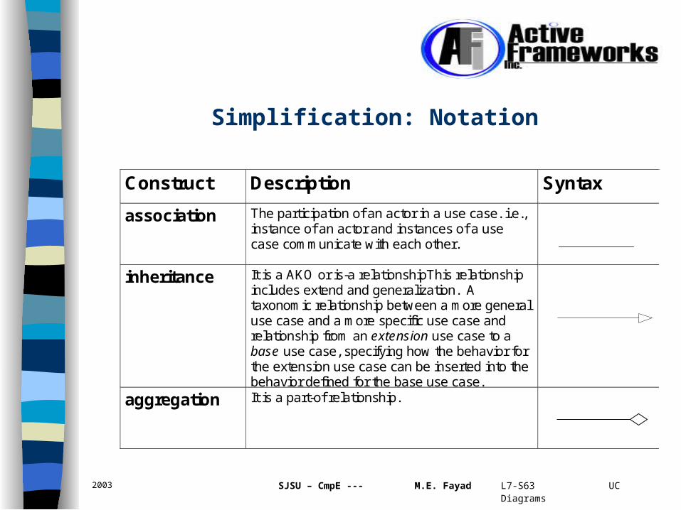
Simplification: Notation
Construct Description Syntax
association The participation of an actor in a use case. i.e., instance of an actor and instances of a use case communicate with each other.
inheritance It is a AKO or is-a relationshipThis relationship
includes extend and generalization. A taxonomic relationship between a more general use case and a more specific use case and relationship from an extension use case to a base use case, specifying how the behavior for the extension use case can be inserted into the behavior defined for the base use case.
aggregation It is a part-of relationship.
2003 SJSU – CmpE --- M.E. Fayad L7-S64 UC Diagrams
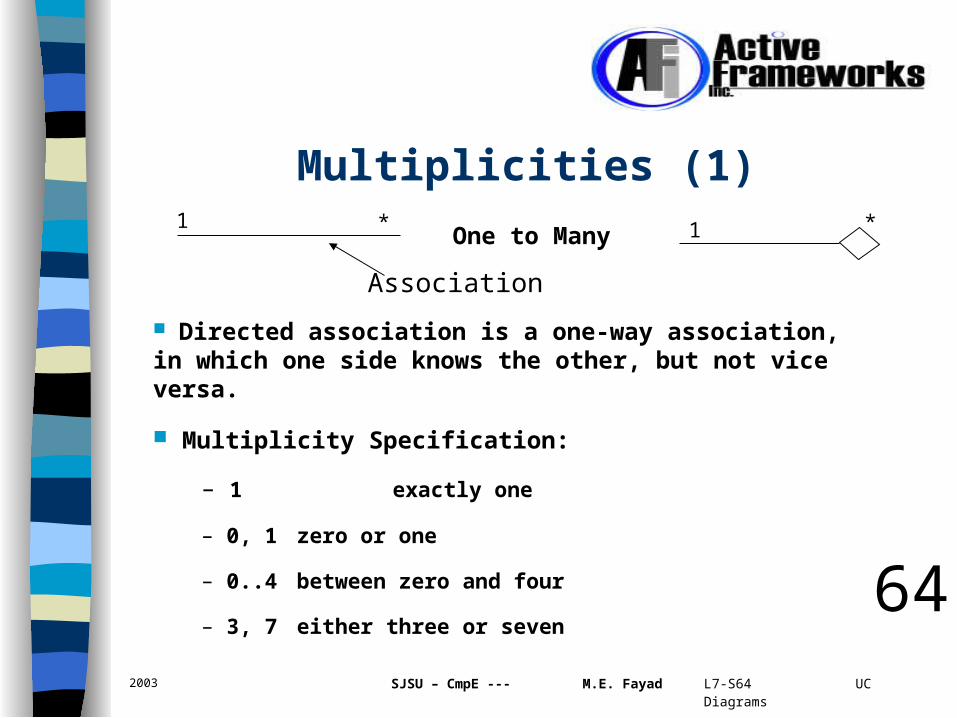
Multiplicities (1)1 *
One to Many 1 *
Association
Directed association is a one-way association, in which one side knows the other, but not vice versa.
Multiplicity Specification:
– 1 exactly one
– 0, 1 zero or one
– 0..4 between zero and four
– 3, 7 either three or seven 64

2003 SJSU – CmpE --- M.E. Fayad L7-S65 UC Diagrams
Multiplicities (2)
More multiplicity specifications:
– 0..* greater than or equal to zero (default)
– * many
– 1..* greater than or equal to one
– 0..3, 7, 9..* between zero and three, or exactly seven, or greater than or equal to nine.
65

2003 SJSU – CmpE --- M.E. Fayad L7-S66 UC Diagrams
Samples of Use Case Diagrams (1)
WholesalerRetailer
supply
sale
*
A supply activity consists of many sales.66

2003 SJSU – CmpE --- M.E. Fayad L7-S67 UC Diagrams
Samples of Use Case Diagrams (2)
WholesalerRetailer
sale
order
*
A sale activity consists of order and deliver.
deliver, pay
11
67

2003 SJSU – CmpE --- M.E. Fayad L7-S68 UC Diagrams
Samples of Use Case Diagrams (3)
68
sale
saleByPrice saleByQty saleBySupply
acceptpayreqPay
deliver
order
salePrice
Different kinds of sales & their constituent actions
2003 SJSU – CmpE --- M.E. Fayad L7-S69 UC Diagrams
1. Define: use case model, a use case, use case diagrams, and, actors
2. T/F
a. A use case is a pattern of behavior the system exhibits.
b. A use case describes how the system does it but NOT what a system does.
c. Use case diagrams are created to visualize the behavior between actors and use cases
d. Use cases are about user’s requirements not about what you might think as a designer that the system could usefully do. 69
Discussion Questions

2003 SJSU – CmpE --- M.E. Fayad L7-S70 UC Diagrams
CRC Cards
Existing CRC Cards
My CRC Cards
How to create with CRC Cards
70
Questions for the Next Lecture

2003 SJSU – CmpE --- M.E. Fayad L7-S71 UC Diagrams
Task 1: Problem Statement for team projects are needed (see sample problems on OOPSLA – DesignFest). This is due on the third week of the semester.
Task 2: Identify the team members of your team. Select a team name and e-mail me, the team name, team’s members’ names, their e-mails, phone numbers -- Immediately.
Task 3: Think about extra assignments and writing essays. E-mail me if you like to start right away.
Please note that problem statements must be submitted electronically as MS Word format. 71
Tasks for Next Lecture