l6 : design, methoding and testing of ci castings
TRANSCRIPT

L6 : DESIGN, METHODING AND TESTING OF CI CASTINGS
Dr. P.K. Biswas Scientist, National Metallurgical Laboratory, Jamshedpur-831007
PART - I METHODING
General Aspects :
Methoding of castings is a complex science. It involves the basic
selection of :
(i) Design and construction of pattern equipment
(ii) Processes and practices for moulding, core making and core setting
(iii) Risering and gating system
Apart from the above technical parameters, clue consideration
sl poi ld be given for economic factors while methoding the castings. The
following points should be considered :
1. Type of moulding and core making process
2. Position of the casting in the mould box
3. Suitable joint line
4. Suitable mould box size
5. Type of mould and core making materials
6. Material specification
7. External and internal chills if permissible
8. Chaplets if permissible
9. Mould and core checking and setting gauges
10. Sequence of core setting
L6-1
11. Provision of vents and flow offs.
12. Number of pieces to be produced
13. Type of material for pattern and core boxes
14. Pattern and core box details
15. Placement of identification codes
16. Indication of surfaces for marking and machining
17. Estimated yield percentage of the castings
While deciding the suitable method of manufacturing the intricacies
of the concerned job should be analysed from all the angles and the final
acceptable casting concept decided, considering the resources available
within the foundry.
The details of the various information that are to be generally
incorporated in the methods drawing would be as follows :
Stage-1 : Fixing the position of casting in the mould
The following questions may lead to a suitable solution for the above
stage :
1. What is the component and its overall size ?
2. Sand thickness between the casting and the mould box ?
3. How much machining allowance required ?
4. Can the holes and slots be cored or can they be cast solid ?
5. What are the areas of thick concentrated masses those need feeding ?
6. What are the tolerances on the unmachined dimensions ?
7. Are there any objections for the use of internal chills and chaplets ?
8. What will be the most suitable mould and core making processes and
materials ?
9. Are there any mechanical and physical difficulties in making moulds
& cores ?
L6-2

10. Are the cores stable or else could they be suitably modified ?
The final desired position of the castings in the mould satisfying
all or the majority of the above questions may be considered for further
critical scrutiny. Appendices A to D give various allowances and
minimum wall thickness of cast metals.
Stage-2 o Selection of mould parting line
The following points should be considered while deciding the mould
parting line :
1. What are the available sizes of the moulding boxes and the machines ?
2. What is the permissible pattern draw of the moulding machine ?
3. How much of the casting part in the drag and cope may be taken
advantageously ?
4. Is there any additional core required for avoiding under cuts ?
5. Does this joint line assists in checking the mould, core setting and
assembly to the maximum extent prior to its closing ?
6., Do we get adequate sand thickness around the mould cavity both from
the stability and strength point of view ?
7. Is this joint line suitable to the moulding skills and practices available
with the foundry ?
8. Does it assist the direct placement of risers required on the mould joint
line ?
Stage-3 Preparation of pattern making drawing
The final conclusion and requirements by satisfying stages 1 & 2 should
be spelt out on the component drawing for the convenience of the pattern
maker. This drawing gives all the possible working details for the pattern maker
and normally covers the following aspects. This is referred as pattern making
drawing and should incorporate the following details :
L6-3

1. Necessary sectional views of the components with clear identification of the mould joint line.
2. Top and bottom parts of the pattern
3. Machining allowances provided on the surfaces required to be ,machined.
4. Pattern draft for easy withdrawal from the mould.
5. Provision of cores & core print tapers for setting and closing as per the standard practices of the foundry.
6. Indication of the ramming surfaces of the cores and the special features for the core boxes if required.
7. Suitable provision for chills and chaplet marks or prints.
8.. Provision of necessary padding if required
9. Provision of general purpose ribs and straightening ribs
10. General contrac ion values for pattern and core boxes
11. Core checking a ad setting gauges as and when required
12. Provision of rubt, ing and joining fixers for important and split cores
13. Mounted or loose pattern supply
14. Provision of lifting and rapping tackles in the case of loose pattern
15. General notes for the pattern makers' guidance with respect to the identification letters, pattern and core box construction practices etc. Other essential details on pattern design and moulding are given in Appendices E to H.
Stage-4 : Selection of I Isering system :
The basic function of riser is to supply feed metals to compensate the
liquid and solidifying contractions those occur during solidification. When
an alloy of solid solution type cools from the liquid state to room tempera-
ture, the following types of contraction take place.
L6-4

1. Liquid contraction - as the pouring temperature drops to the liquidus temperature
Solidification contraction - as the casting solidifies completely.
3. Solid contraction - as the temperature cools from the solidus to the room temperature.
The first two types of contractions are compensated by feed metal
from the riser, while the last type is taken care of by the pattern makers'
shrinkage rule. The contraction allowance is different for different metals.
Generally it is 2% for steel, 1% for gray iron and S.G. iron and 2.5% for high
alloy steel.
There are various methods available for riser calculation viz.
1. Heuver's Inscribed circle method
2. Caine's method
3. Shape factor method (NRL)
4. Modulus method (Wlodawar)
I. Inscribed Circle Method
In this method the heavier sections in the casting are isolated and the
largest possible diameters of circles are inscribed. The diameters are the
measure of the mass concentrations in the casting and are known as hot
spots.
A stepwise procedure of calculation is as follows :
1. The Sections of the castings which require riser are drawn to a
convenient scale together with the machining allowance.
L6-5

2. Diameter of the largest circle 'd' that can be inscribed in the section is
then determined. This is usually termed as 'hot spot' diameter.
3. The diameter of the riser 'D' is obtained from the relation D = fd where
f is arbitrarily taken as 1.5 to 3 depending upon the section to be fed and
partly experience with similar castings.
4. Riser height H 1.5 D except in cases where exothermic compounds are
added to the risers,
5. Number of risers are obtained from the relation that a riser can feed upto
a distance of 2.5 times its diameter. A final adjustment in the riser
diameter as determined in Step-3 may be required before finalising their
number.
6. Riser is then joined to the hot spot by providing suitable padding to the
casting section for promoting directional solidification,
chills are used for hot, spots where it is not convenient to provide riser.
2. Calnes Formula
Chorinov's rule (solidification time in proportional to (V/A)2 ) has
been elaborated by Caine by introducing a factor called the relative freezing
ratio (X). Relative volume ratio (Y = V riser is plotted against A casting
(A/V) casting X =
(A/V) riser
The curve obtained experimentally divides the area into two regions
- sound and unsound. Any point in sound region can be used for riser
design. This is laborius and so not popular.
L6-6

3. Shape Factor Method (NRL method) :
In this method a shape factor was introduced to take care of the
shape of the casting. It is defined as :
S = Length + width L + W
Thickness
Volume ratio (Y) as diffined above is plotted against shape factor on
X-axis. From this graph riser volume can be calculated in the same manner
as Caine's method.
The above method lacks accuracy. However, computation in shape
factor method is less tedious and quicker than Caine's method.
4. Modulus Method
Wiodawar has recommended a method of riser calculation in which
the number of simple geometric shapes that can be accommodated in the
casting is first determined. From this, the m.odulii (V/A) are calculated. The
fliMilthis of ris(-1- for eael-I geometric shape is obtained front the relation.
Modulus of Casting 1
Modulus of riser • 1.2 MR = 1.2 Mc
Consideraing h/d = 1 to1.5, dimension of riser can be determined.
A similar equation for the contact area of riser has also been given.
Modulus method is a further simplification over the shape factor method,
since a number of suitable graphs are available for modulus calculation.
Foundries, which have computers will probably find it more useful to
employ these graphs to computerise their riser calculation.

The riser should solidify after casting i.e. solidification time of riser tH >
t, the solidification time of casting . In view of the above, the modulus of the
riser must be about 1.2 times that of the casting. To obtain an absolute
guarantee that the neck should not • solidify before the casting, the neck
modulus is taken as 1.1 times that of the casting. Hence the following
relationship is commonly used :
M casting : M neck M riser = 1:1.1:1.2
Use of Chills :
Metallic chills are used to produce thermal gradients by extracting heat.
With the end chills, feeding distance for a plate and a bar casting can be
increased by 2 inch and equal to the section thickness respectively.
It has been proved experimentally that for the chill to be fully effective,
its thickness should be kept in the following proportions :
(a) Chill thickness for bar (Tc) = 1/2 section thickness to be chilled
(b) Chill thickness for plate (Tc) = Section thickness to be chilled
Chill should be equal to its thickness and the length should not exceed
01 3 Limes the thicluie'ss. If the chills are too long, they should be cut to 2Tc
length and should be spread 1/2 Tc apart.
Stage -5 : Selection of Gating System :
The purpose of gating system is to introduce liquid metal to fill the
moulds cavity without creating any problem are defect in the mould, melt and
final casting.
The gating system can be broadly divided into :
1. The entry section - consisting of the pouring basin, sprue and sprue base
L6-8

2. The distribution section - consisting of the runner and ingots
The entry section has two functions :
1. To supply metal free of entrapped gases, slag and eroded sand
2. To establish a hydraulic pressure head which will force the metal through gating system into the mould cavity. Similarly the distribu tion section has five functions :
a) To decrease the velocity of the metal stream b) To minimise turbulence both in the gating system as well as
in the mould cavity c) To avoid mould and core erosion d) To ensure minimum drop in temperature of liquid metal in the
gating system e) To regulate the rate of flow of metal into the mould cavity.
In addition to the above, the gating system should be simple to
mould. Various types of gating systems are in practice depending upon
size, complexity, weight and method of production of castings. They are top
gates, bottom gates, horn gates, parting line gates, etc.
Design of gating system -
Stepwise calculation of the gating system are as follows :
(1) Calculate the optimum pouring time using empirical formula :
DIETERT has used an empirical formula as follows :
Pouring time (sec.) t = k\iw
where k = const = 1.0 to 1.5 (smaller k value for large castings)
w = gross wt of the casting
(2) Calculate the choke area that controls flow rate usingfollowing
formula :
L6-9

Cross sectional area of the ingate = Ag =
0.31 vt-Vhcff
Where W = weight of the casting including the weight of runner and risers
(gross weight) in kg
v = flow coefficient (Table-1)
t = Pouring time (sec.)
heff = Effective ferro static pressure head during pouring
Table - 1 Flow co-efficient v for steel casting
Type of mould Resistance of mould
High Medium Low
Green sand
Dry sand
0.25
0.30
0.32
0.38
0.42
0.50
l'he effective ferro static pressure head can be found out by the
formula :
hcff = - P2
2C
Where Ho = height of the metal column above the gate (cm)
P = height of the casting above the ingate level (cm)
C = Total height of the casting in as-cast position. (cm)
(3) Fixing.up of the desired gating ratio :
Gating ratios recommended by various theoreticians in the literature
vary over a wide range. For steel castings a mildly pressurized gating
L6-10
system is used. In an un-pressurised gating system, the area of runners
and gates are larger than that of the sprue; eg.
1 : 2 : 2 or 1 : 4 : 4
A mildly pressurized gating system of 1:2: 1.5 will minimise ail'
aspiration in gating system and produce uniform metal flow.
(4) Based on the gating ratio select, the down sprue, runner and ingate
sizes.
(5) Incorporate the following details in the gating system
(a) Take the runner bar in the top box and the ingate in the bottom
half of the mould, wherever possible
(b) The runner bar should be extended beyond the last ingate at
least by 2inches.
(c) If atmospheric side risers are to be provided, consider the
possiblity of gating through risers.
The above aspects of risering and gating principles (as described in
Part-I) will be further clarified from the sketches and worked out problems
presented along with this text.
Risering in grey iron castings :
The risering of grey iron required special attention because of its
solidification history. As per Iron-carbon diagram, solidification of a 3%
carbon grey iron occurs in two steps :
L6- 1 1

(i) Liquidus to entectic temperature (1133°C) in which austenite den-
drites separate from the liquid.
(ii) At the entectic tempeature where duplex precipitation of graphite
and austenite takes place.
Since austenite is a denser phase than liquid iron, contraction takes
place while cooling from the liquidus to the entectic tempeature and
therefore feed metal is required from a riser during this interval. During the
entectic solidification, however, expansion takes place, since the density of
solid entectic structure (y+ graphite) is less than that of liquid phase. At the
entectic tempeature, therefore, metal flows back from the casting to the
riser. This process is known as purging. If in the grey iron casting, the riser
is small, and has frozen at the top, due to purging great pressure will be
developed in the casting and it will bbow outwards. Hence care should be
taken to keep the riser open to atmosphere \ so that the pressure in the
casting is easily retrieved without any distortion. Rice husk can be put in
the riser top to protect radiation and keep the riser hot.
Gating in grey-iron castings
Fluidity is of great importance in the design of gating for grey iron
castings. Fluidity of grey iron decreases with decreasing C&Si content and
with lowering the pouring tempeature. Maximum fluidity can be obtained
more readily oby raising the temperature of pouring rather than stressing
very much on the composition factor. Pouring, therefore, should be done
at high tempeature and with a fast rate through a cumber of ingotes. There
is, however, an optimum pouring rate for grey iron castings. If the pouring
velocity is higher than that recommended, the poured metal drags the slag
into the mould cavity. High velocity pouring also causes mould erosion
and gas entrapment. In low velocity pouring, the metal cools rapidly and
may result in misrums. In grey iron casting, the gating ratio is usually of
L6-12

the order Of 1:2:1, 1:2:0.5, 1:4:1. 2:7:1 etc. Slag and dirt traps are used in
the gaffing of grey iron castings because of their great tendency for slag and
direct formation. The common practice is to keep a full sprue-during the
pouring period because full sprue helps to prevent slag from entering the
mould. Strainer cores are often used at the sprue base for regulating the
flow and maintaining the sprue full.
L6-13

DNII
SVO
'V
1-6
CD
CD
0
frc3 m
CD
C)/0,-
Cr)
0
/....... ,....1 ■̂...•
).....1 . ,■1 9 I■1 . 1.4 . )...
, 1•••■• • ,.......,
N...., ••■■•,
C) 0 0
- a w
P . (-•.- CD CD
E, ct,;.
ff CD CD Cn
ca, 4
CD ,-_
.) 2t..
S P) cp p
o 1 ,i'` r-± p
CD i
g. '-' Grq
S:21,
0
R rD -
. -: c) n
CD = a) (,)
2. 0 i_ ,-cs
, a, CD 0
CD CD CM Cn CI) p
)2. " rt-
R, .. 0B Sl) Fj ti R,
CD cD P 0
. a 6 '- 0 (-i,
cm, (I) 2. P
(-) (IQ
g' ',' S C)
S 0 o o 0 o
cp P,,,D CrA P-
c;1 cp P ,9, hzi Q
LI " 0 2,, ,0
, g .?Ts
0 c) cict k7 w no F,1).) cc.
CD 0., g 0
ci )... . • (7) 0
. )1 c:r.
o 0 C• AA
S (+1 o )-+) CD
Q... 0 o n ci) • 0 cp 0
O 0 w A) cn
CD CD
E Cn
'73 . cg
°-'4
o
,..) „_, ,, -1- CD 6
CI 0
M GM Cn
I-Ci cD m
r+ CD W"
CD ,"1-1 (I),, . 0
)21 8• P.
-LlI
saci
u-f-l.
sED

0
.r4
cu
ca ♦
0
ba
'§
-‘4
•
r-4
•
r..1
Qua
lity
of s
uper
visi
on a
vaila
ble
cn rti0 05. -6.4 7i
........ Clz 41.) )-4
1(c) a)
u) (1)
0 0 0
cy4 co -c.)I 0 al V
11Z/ cj c
▪
d Cf) 43.) ‘0,0 0
)
a) t--4 cu .. 0
E •B •E ",..... .,...i 0 CO I) >1 (ii .° (n
• r-I (1) En ,..4 0 -4..., ai ,..) CO Q .1-4
r- C1-4 c7!z$ 0 ,2 • 0 cl 0 1-4
0 (0
0 :4 cd
0 o V 8 ill -_, 0 cd a) 78
o cd 0 :-.11 ,0 0 • 0 5 Q.4 d a) cii, > g 4-j0 a) 734 cu v •
-, cd '0.0 ;-4 -.-> *R 8 ,63
(1) ..4
_L1), 0 ba > 0 E.) 4 w 2P1 'BEd
........
Clz
41.)
)-4
1(c)
a)
u)
(1)
0
0
0
cy4 co
-c.)I
0
al
V
11Z/ cj
cd
Cf)
43.) ‘
0,0
0
)
a) t--4 cu ..
0
E •B •E
",.....
.,...i
0
CO
I)
>1 (ii .°
(n • r-I
(1) En
,..4
0
-4..., a
i ,..)
CO Q
.1-4
r-
C1-4
c7!z$
0 ,
2
0 cl
0
1-4
0 (0
0 :4
cd
0
o
V
8
ill
-_,
0
cd a)
78
o
cd
0 :-.11 ,0
0
• 0
5
Q.4
d
a)
cii,
> g
4-j0
a) 73
4
cu v •
-, cd
'0.0
;-4 -.->
*
R 8 ,6
3
(1)
..4
_L
1), > 0 E.)
4w
2P1
'BEd
Cas
ting
app
licat
ion
tole
ran
ces
C.)
0 :41
:4g
cd
C.)
Fou
ndr
y sk
ills
cr3

,
5E cra 0
rd
ci)
uTpT
-no
Lu p
t ruH
CD o .CD p. ""C:1
r+ o F
Cro,
M.
Cl)
cro CD'
'-zi 9 '71 U) )--d r-*
o 0 ca. a CD 1--;• r-t-
CD )--.• CCti' )9
?-1
CD 0 Ci., 't:i
n . 04 0 6 cro, '-'•
CD )-•
Gr.L: L-4 ,•,'-1 .. 0 r-t- CD
tl CIO, ' " 0 )-1
1-t co p..),, -. '*d 0 0 E FLi . 0 q
ci) ci. z CD
C`' (f) ,-o rt- E
C5)
' fa )--N (") 2 ti g )"-.
0') —
0, () 'V) 0 :-.1 P-,' gq - '-c:J ,0 '''.. ,t ., . . '
0 (,) p.)
,--/ 0 --. o E 4
.,---t. c
r8: 0 6' 'a cn R. (n
.-. c-D r-r-
cn CD . 0
(J) t-i (i(: 5 CI' i Cro,
r+. CT"C5 Ca. O.: 0 hi 0 M' Cfcl 0 0 -1:i
.. ak 0 C/0, V 'd '-I
,-.9 7--1
0 04 04 t? It) '--‘ — cn ''....Cn Crq -1 (1),--
'
■••••. CD Q., 0 CD :1., CD. sg. 0 ca, n c-I-- 0 11 0 '1. I '-c--3
P — .- 0 ,...)- (/) . )-1 )(71:7‘ 5 ( 0 0 Ork CP CD - Cn ri V
1--i C) FF. _ ,-ci 0 c) 0 5 ri) ;--). ., (11' cc/D1 '5' 4 0 cfq p-c3
. 0 a) , r -t- CTO, A „_,(1) , cr p) oe, 0 'FD" 0 '"0
F--)F, Fl- t--t- -,--., N...., ,-.• < 4.
0 F"• ' CD r+
0 w "I Cr' c) ■-ri. o 0 '-izi P o — 0 l-t o I:3 0 0 o
0 aq p o „5- ca, CrO■ (7 E 8- . ,- 0,. ,i 0 0 'ICI (/) CICA
)--.• 0 tz. ---4 (-ID 0 W 0 s---- 0 ,_,
•
Fci r). t- ' 7' )--,- ■-0 CD 0 )'''` CD P n) M cr Crq Cr(:), 0 1:,
b-i CM, cp 2 .(1) o Pi n O
...
E ,_,.., a) 0 ,.. 0 >I ''
,-F o :: 0 cn ,---, a. (.0
,--,-- (1) „EL ., 1 --1 - ..--,-) (fq ■-s cn .
u 0
0
0
0
0

0
9 _q
,
Va
(,)
) 7
:-.. -+-.- i .Q
af)
3 00 .
)
C74 C5S
(1)a4 PO u) al ti, a-, .0 (i)
0Qgcz sbil t a
09 .(I)
cei • g ad .5 K -413 O
cu ro 0 itu }-4
+ , 0 r—w- " 0 ,..0 cd rai al 10,(1) 8 1 'c'.,
73 r'' b.e, ro co ro bb u., .d E-4 .tto ra4
•,..) ,... ..., .F.-), cu o 1-4 W a) '. • 5 a) 4-) 1-4 s (1) .) 0 0 . _4., -ari kao E 0 0 as rt • 4-4 0 • 0 ,cp 0 0 Q $_,
o 4 a) 0 E hA/-4 2 b) 5 0 -.) 6. 0 +,
r.9-i ,. cir- aai al c n.th' cb :4.1 0
• •5 4 -7J .p 6-4 V '0 .5 -.- ...-2 (J cd .a) 6 --, tv) *0
cu 1---ci El
O r., vi 43 'L) Ir'M a) a) o - c#4
0 cu
.0 > ,coci . H
,. bo w _, a co ct a c --) '+L3 4-s 0 kJ 8 7). g.05) ,A0s) (1) cz 0 a) 2 1-'
,...), - 13 O (+13 -4,., 'V) 4a) 4a' 9 0 2 (7) ti bo 'V, a Q.) o .
(,) ..._ H co 0 4aj 5 • 0 .a.) 0 0 to Ts cu .23 q 13 (%' ra4 U 00
Shel
l m
oul
din
g
Hig
h p
ress
ure
mou
ldin
g
od 16 Cfl

sp
ajaa
'1.4-4s
0
potn
aw
Avu
nog
O o r) CD 0 r)
o Ct, i Pa
, E 0 E.
'•
cot n
co t- E. aq
cx. ,ci x) 0 w 1 O E. -, m.
a '-ci 0 w
0w A) 0 co
,-*
0
r--4i, tii (rive 0 N 0 ccin, 0 g 69. " 4 2, g p,
.9 P`)). Fi- o 0 r-t- 0 — o-ct )... b' F-3- o 9 cja (6
0 In PLY
,... _
'-cs , GnA QA ccri..- c .) 0- 0
R rD V'
0 P . R. - 0
o cn k 1--- 0 co A.)
CD fa, a
''" b-.' C I )
CD A) ) .scp cn clic) n'''P, a. 0
rD .--t- ci)(1) -&j in, ,_ 0 0
r-eg P;PD k3;13,., E. cr.°. 0 p., < ci.
,...,.. , (-D o ,L, ,.. L-2... 0 (1) t- ■-.,----i
r-io.c, .--t Q. .-t 0
2 , rD'-' 5 Cr4 ‘r'CI (1)91 'C-11) ‘-‘9 P' cn
c-r- P2. 0 0 CD 0
coD ..-1
co 0 o 0- o 70, at c4 (0 p.) o 71 T. ra,
t-il rD
c/9 6.-ci• 0 o t..., .,
fie° 0 p W
tSt-) " ;:: q O
g cm 0
a q:3 •
. 'ci a r+ r..--'.. co i-p
0 FI.. 0 a w ao.
cn 1'4 0 ctp-
ri r_t_ P
e_,..-• 0 m 0 ,y,. 9_, P Pci 4.
cn po 0)
CD 0 •-11 ("D
)-1 43 0 C7' 6 A 0 8 .1 O '.̀ 0 Gro, -` = 0 w O CD 0 0 Cn 0 0 Ca. W H
-.1 0 Cr m (-D rD
, 0 $ ). V' w CD ),--D- E,
, 0 0 N 0 < r, CD (1) ;,',1 • .-,
■--.1 0, )-cj sl) ,-cl o )73
CD $71.) 04 m
pt. (-+' A)
a. F,±^"' 0
3 hi ..,„ r-f-
4. 9) q.: 1-1 CD ' el (I)
ff cnc° la.
CD r4 0, a.
1,3 ''' (1) ,sz) cn ,--.1 CD CD 4 (2 4. P.. G. 4.
0 O. i1 .51) 0 15 WG r, .
0,--
0 o ci, ci` ,,--'0-
P o
. < a 0 6,
0.) ia-: 2 cc, " - 74t fn",
q:i clq--3
14) m t, . - _ 4 0 uo, 0
Pt 9 Cia R
P (-, ecp, O z. Cn a)(1) (-) 'c.3
ci) g 0 R -1 a.
(-,- - ■-t 0
Q. A) Co si)
Cf)
PD P - -',5-.
,.....0 0 ).-, .. --,
w po 0)
w w 8.. w p_t: 5' rt) P
fa68, g CR a

Patt
ern
lif
e ba
sed fa
cto
rs
rC
(TS fal $--4 a)
L., o 0
a) a)
cizS Z
Foun
dry
meth
od base
d fa
cto
rs
4.
Gati
ng
& Ris
erin
g
Pre
cis
ion
bas
ed fa
ctors
PART-II
A. CASTING DESIGN (General)
Objective : (1) To achieve desired internal soundness in casting
(2) To evaluate a design which will reduce moulding,
cleaning and machining costs.
GENERAL DESIGN RULES
Rule-1 : Before issuing the final drawing consult a competent
foundryman or pattern maker
Casting design poses two problems : One for the engineer, the other
for the foundryman. The engineer must know "HOW TO DESIGN A
CASTING SO THAT IT WILL ACTUALLY HAVE THE REQUISITE STRENGTH
AND FUNCTIONAL PROPERTIES "
The foundryman must be able to ' MAKE THE CASTING SO THAT IT
I IAS THE STRENGTI I AND 'Ft iNcrrioNAL PROPERTIES THE ENGINEER
INTENDED"
Rule-2 : Construct a small model or visualise the casting in the mould
A model to scale or full size in the form of pattern that can be used
later will help the designers to see how cores must be designed and placed
or omitted. It will help the foundryman to decide how to mould the casting,
detect casting weakness (shrinkages & cracks), where to place gates and
risers, and answer the questions affecting the casting soundness, cost and
delivery.
L6-20

Rule-3 : Design for casting soundness
Lack of metal soundness in a casting is one reason for lower than
optimum mechanical properties. The foundryman by using a sufficient number
of foundry techniques such as gating, risering, chills, padding and thermal
gradients can usually produce soundness even in exceedingly difficult cases of
poorly designed castings. However, if certain principles are observed the job of
producing soundness and uniformly good properties can be made easier and
less costly.
The most important criterion for soundness is the principle of Directional
Solidification. Here solidification is controlled to proceed from the thinnest
section; progressing through the heavier sections towards the riser. The
common methods of applying this principle are :
Use of i) taper
ii) padding
chills
Taper : Tapered design of a member of a casting is to increase the dimension
progressively towards one or more suitable locations to make pattern with-
drawal easy and also maintain the temperature gradient.
Padding : If a continuous taper is not possible, the designer employs metal
padding to bridge the gap between the heavy section and another isolated heavy
section. Padding would increase the cost of the casting. Further if pads are to
be removed later from the casting, additional machining expenditure would be
involved. So it is advisible not to use pad as far as possible unless it is inevitable.
Chills : Chills are metal obj .';cts placed at heavy section to induce faster
solidification. They are incorporated into the mould or into a core by
ramming sand around them during moulding or core making. Further in
L6-21

silica sand moulds, either chromite or zircon sand, possessing higher
thermal conductivity may be used as a chill material.
Rule-4 : Avoid sharp angles and corners
Fillets have three functional performances :
a) to reduce stress Concentration in the casting in service,
b) to eliminate cracks, tears and draws at re-entry angles
c) to make corners more mouldable and to eliminate hot spots
Rule-5 : Reduce number of adjoining sections
Rule-6 : Design for uniformity of section
Rule-7 : Proportion dimensions of inner walls :
Inner sections of castings, resulting from complex cores, cool much
slower than outer sections and cause variations in strength properties. A
good rule is to reduce inner sections to 9/ 10th of the thickness of the outer
wall. Avoid rapid section changes and sharp angles wherever complex cores
must be used, design for uniformity of section to avoid local heavy masses
of metal.
Rule-8 : Avoid abrupt section changes - eliminate sharp corners at
adjoining sections.
L6-22

HOT SPOTS, JUNCTIONS, RIBS & BOSSES
A hot spot is a location in a casting where a heavy mass of metal is
allowed to solidify compared to neighboring sections. This location will
solidify slowly and may contain a shrinkage defect. There are several simple
design rules to avoid this problem.
Inscribed circle (Heuver's circle) :
The presence of a hot spot can be easily identified by the method of
inscribed circle. Considering a L shaped corner at the junction point the
diameter D of a circle drawn will be the greatest of all the inscribed circles.
Chvorinov's rule that the solidification time is proportional to the ratio of
the volume square to the surface area, is applicable at that location. The
increased mass of that junction is proportional to (D/d)2. This ratio must
be as small as possible to reduce the problem of hot spots. _
L-junction : A sharp internal corner will cause a stress concentration.
At the same time, a fillet with a large radius will lead to a bigger hot spot.
The fillet radius should be carefully decided.
For steel castings, the general design rules for fillet radius are as follows :
i) for T < 25 mm, r = T
ii) for 25 <T < 75 mm, r = 25 mm
iii) for T > 75 mm, r + T/3
These rules can be used for other castings as a general guide. An
external corner can be rounded with a radius of 0.1 to 0.2 T.
L6-23

T, Y and Xjunctions : In general X-junctions are difficult to cast sound and
they also give rise to high stress concentration. They can be replaced by two
T-junctions by an offset distance. Another method is to provide a cored hole
at the X-junction.
Ribs : A rib can be used to improve the strength of a bracket so that equal
section thickness can be provided in the casting. A rib should be as thin
as possible but should not be too thin to act as a cooling fin.
It is to be noted that joining a rib to a plate section can be treated as
a T-junction.
Bosses & Pads : They can be locations of shrinkage defects. They should
be blended into the casting by tapering or flattening the fillets. Further,
providing a cored hole at the boss may eliminate shrinkage problem. When
there are lugs and bosses on one surface, they should be joined to facilitate
machining.
Hot tears and cracks : Hot tears and cracks occur most often in locations
of sharp changes in sectional thickness. Hot tears are produced at high
temps when the metal is weak while cracks are usually formed at low temps
when the ductility is rather low. The design rule is: it is made with a proper
fillet or taper.
Rule-9 : Design ribs & brackets for maximum effectiveness :
Ribs have two functions: one to increase the stiffness and other to
reduce weight. If they are too shallow in depth or too widely spaced they are
ineffectual. Correct rib depth and spacing is a matter of engineering
design. Ribs meeting at acute angles cause moulding difficulties, increase
L6-24

costs and aggravate the risk of defective castings. Instead of plus joints or
X-joints a honey-comb design creates more uniform cooling conditions.
These types of ribbing assures improved strength with minimum risk of
distortion and structural weakness.
Rule-10 : Bosses, Lugs & Pads should not be used unless absolutely
necessary
Bosses and pads increase metal thickness, create hot spot and cause
open grain or draws. Blend into castings by tapering or flattening the fillets.
Bosses should not be increased in the design when the surface to support
bolts etc. may be obtained by milling or counter sinking. When there are
several lugs and bosses on the surface, they should be joined to facilitate
machining. If possible use uniform thickness instead of many pads of
varying height simplifies machining.
Rule-11 : Design for moulding
The design should be such that moulds can be economically produced.
Such features as irregular parting line, undercuts, outside bosses, use of
cores & loose pieces all affect labour cost, casting quality and cleaning cost.
The most important consideration is the determination of parting line.
Parting in one plane is preferable and simplifies moulding. By changing
design to a single parting plane, production cost can be greatly reduced. It
is desirable to have heavier sections located at or near the parting line
where they are easier to feed by risers
Undercuts require loose pieces for moulding, and in most cases, the
casting can be redesigned for avoiding this.
L6-25

Outside bosses which are not on the parting line recitiire coring or use of
loose pieces. Therefore, pattern and moulding costs can be reduced by
eliminating the outside bosses.
Efforts to reduce the number of cores greatly minimize moulding and-
production cost. In general, deep pockets on the surface of the casting
increase moulding cost.
Cored versus drilled holes
It is however, important to consider provision of holes by employing
cores instead of drilling holes. later. In general holes of diameter greater
than 15mm can be cored. A cost analysis should be made. Sometimes,
instead of placing a core a depression can be provided on the casting
surface to reduce the cost of drilling.
Design for core support
It is important that cores are supported well in the mould and have
adequate strength. The thickness of the metal section surrounding the core
and the length of the core, both affect the bending stresses induced in the
core due to buoyancy (lifting) forces of the metal. Therefore, certain
minimum core diameters are recommended for cylindrical sections. For
instance, consider a hollow cylinder of length in the range of 150-200mm.
The minimum core diameter suggested is about 100mm with the metal wall
thickness in the range of 100 to 300 mm.
The use of ch_aPtlets for core support should be avoided as far as
possible. Chaplets often fail to fuse completely with the casting and result
in porous defective areas.
L6-26

Rule-12 : Design for Cleaning :
The cost of removing cores from casting may be extremely high for
certain inaccessible areas. Cast-weld construction can be done to eliminate
the core and to avoid cleaning the cavity.
The casting design should provide for openings sufficiently, which
permits ready access for the removal of sand core. There should be proper
access to clean the internal surface by shot blasting and grinding. The
removal of core rods should be easy, otherwise the cleaning cost will go up
and casting also may be damaged.
Rule-13 : Design for machining :
When a casting is to be machined to a close tolerance, it is desirable
to do as much machining as possible without removing the piece from the
machine. For this a chucking extension is suggested. Castings with tapered
sides are difficult to hold in a lathe. Pads or flats can be provided. For
irregular shapes, lugs can be provided in the casting to facilitate easy
clamping on the machine table. Hooks or lugs arc provided in the design
for easy lifting and transporting of the casting.
Rule-14 : Wave construction
This design principle is meant for relieving internal stress and for
avoiding formation of cracks. It requires the use of curved members which
are slightly waved or curved. A typical example is the use of curved spokes
in wheels.
Generally an odd, number of spokes is preferred instead of an even
number of spokes. The flange section and hub cool at different times and
L6-27

cause a pulling or tearing action on the spoke due to contraction stresses.
Consequently an even number of spokes will result in tensile pulling of
opposite spokes. This is avoided by having an odd number of spokes.
Rule-15 : Design for elasticity & avoiding cracks
The shrinkage in the castings can vary considerably from one part of
the casting to another. These shrinkage variations give rise to internal
stresses which show themselves as soon as solidification takes place, the
metal then having little strength. They can be the cause of cracks and even
fractures, if the profile involved cannot withstand a certain amount of
deformation.
Rule-16 : Redesigning
Either fabrication, forging or cast iron component can be redesigned
as a steel casting. The benefit of redesign is for improved integrity, reduced
cost, greater strength and improved production rate or service life.
Design Stages
For the development of a newly designed casting, the steps are :
1. Make sketches of the casting
2. Determine the forces upon the casting. In some cases this may be difficult,
3. Calculate, if possible the metal sections needed to operate under these forces
4. . Fabricate a wood or clay model
L6-28

5. Make a pattern layout
6.` Make the pattern equipments, (temporarily)
7. Make a trial casting (if necessary radiograph for shrinkage defects
and correct the design)
8. Perform a brittle coating test for stress analysis,. the casting should
first be machined as it will be in service
9. Locate areas of high stresses
10. Measure the higher stress with wire strain gauges
11. Remove metal to eliminate or reduce higher stresses. By causing
high stress to spread over a large area, these stresses are reduced.
12. Redistribute metal to eliminate or reduce higher stesses
13. Make another trial casting with modified design now.
14. Thoroughly test and make additional changes. if necessary
15. Release for production
16. Make production type pattern equipment. While preparing the
drawing of casting, the foundry engineers may provide the
following information
parting line
gate & riser locations
• draft
• machining allowances
• casting tolerances
• Cores
• locating points to be used in initial machining.
L6-29
II-B : CASTING DESIGN OF GREY (FLAKE GRAPHITE) IRON
1. The moulding methods, the casting properties and the casting design as
regards to flake graphite iron are inter related. A judicial selection can
optimise the casting design. A flake graphite iron poses little problem
with regard to foundry defects of the mechanical properties obtained
therein actual practice. Care is required to make best use of what is
feasible.
2. Flake graphite can have narrow freezing range and form an eutectic at
selected compositions. This inherently decreases the tendency to form
casting defects like shrinkage and porosity.
3. Graphite expands on solidification and accordingly when the flake
graphite iron solidifies, the need for external feeding is greatly reduced.
4. Fluidity of cast iron is much higher compared to various other materials,
and hence complicated shapes can be cast: with case.
5. TI j,f,eneral rti ties to avoid the ill effect allot spot are equally applicable.
to cast iron.
6. Various moulding processes can be employed for producing flake
graphite irons. Sand moulding is one of the most conventional moulding
processes employed for producing flake graphite iron. For closer dimen-
sional tolerances ofvery intricate shapes, shell moulding is adopted. For
improved pressure tightness application, flake graphite iron are pro-
duced by gravity die casting. High pressure moulding are also adopted
• for flake graphite iron. Particularly cylinder blocks for automotive
vehicles are moulded by this process. The economic feasibility for
choosing a particular moulding process for flake graphite iron depends
L6-30
on the quantum, the minimum section thickness to be cast and the
engineering properties those are required. They have to be tackled
separately. As a case study, simple shapes like cast iron pulleys can
be sand moulded using machine moulding. The quantum here can
justify split patterns to machine moulding. The cylinder liner which
is a hollow cylinder in shape on the other hand is an example for a
centrifugal cast iron. This is so because the cylinder liner is thor-
oughly machined from all sides. The major criteria here is productiv-
ity and high yield. A different machine tool casting like the column for
a vertical milling machine is invariably hand moulded. Assembly of
cores leads to production of such casting. A scooter cylinder block on
the other hand involves casting of thin fins and complex geometry
and accordingly a shell moulding can be most optimal process to
achieve such intricate castings.
7. Centre line shrinkage is a phenomenon observed when lateral
solidification is greater than longitudinal solidification. It not only
depends on a casting design but also on the alloy. Flake graphite iron
poses relatively lesser problems with regard to centre line shrinkage.
When the carbon equivalent is lower, then there is a tendency for
more problem than when it is higher. As the composition tends
towards more and more eutectic, the tendency to exhibit centre line
shrinkage decreases.
8. The pattern materials and gating designs vary according to the type
of moulding or casting method.
Pattern can be one piece pattern, split pattern, match plate pattern,
multiple pattern, skeleton pattern, sweep pattern.
The pattern material can be wood, metal, epoxy resin or polystyrene."
L6-31

9. The dimensional tolerance for sand casting and gravity casting for
different casting dimensions can be as follows :
Moulding method Casting dimension (mm)
50 100 300
Sand moulding (best pattern)
Gravity casting (die)
±1.6
±0.5
±2.9
±0.7
±3.5
±1.2
10. There are various allowances that are to be given to the patterns.
These are draft, shrinkage allowance, distortion allowance, machine
finish allowance, rapping allowance. The draft is given to facilitate
easy removal of the pattern when it is given on vertical surface.
Normally 3° to 1/2° - 3° for hand moulding or shell moulding. For
hollow surface, inner taper has to be reversed. No definite allowance
rule is available. It is usually based on observation and experience.
Machining allowance is provided for removing the surface irregular-
ity. Normally for flake graphite iron 1/8th inch is considered as an
optimal machine finish allowance. Rapping allowance is given to _ .
facilitate removal of pattern with- easy withdrawal.
11. Hot tearing is a phenomenon influenced by casting design. If a crack
comes above the solidus, it is known as 'hot tear'. In such cases, the
crack exhibits side branches. If the crack is below the solidus, it is
due to internal stress and does not exhibit side branches.
.Flake graphite irons are rarely susceptible for hot tears. In fact, as
the carbon equivalent is higher, they are not at all susceptible to
hot tears.
L6-32

12. Flake graphite iron is a section sensitive material. Mechanical
properties are largely decided by the cooling rate in addition to the
chemical composition. The larger cooling rate, the material of
identical chemical composit ion can give higher hardness and strength.
Above a particular value of cooling rate the grey cast iron can solidify
mottled or at times white. This tendency is referred, as chilling and
there is a limitation to minimum section thickness to which a flake
graphite iron can be cast without producing chilling. Normally 6mm
thickness and above is suggested for flake graphite cast iron. The
higher the section thickness is, the higher will be the coarse graphite
and more of ferrite in the matrix. This can lead to deteriorating
strength levels. For instance, a flake graphite iron casting having
6mm section at one location and 50mm section at another location
can recordsignificantly different properties.
13. The tensile strength is assessed on separately cast test bars pro-
duced alongwith every batch of castings. At times, specific locations
in the casting can be tiurned out into miniature test pieces which are
tested in a tensometer to assess the tensile strength of the casting.
The latter method is very reliable as the actual casting can be tested
rather than depending on separately cast test bars.
14. The microstructure studied involve assessing the type of graphite
flakes, size of graphite and the matrix. There are in all five different
types of graphite flakes viz: (1) uniform distribution and random
orientation, (ii) rosette grouping (iii) super imposed flake size and
random orientation (iv) interdendritic segregation and random
orientation, (v) Interdendritic segregation and preferred orientation.
These are also known as type A, B, C, D and E graphites respectively.
L6-33

There are eight different sizes of graphite flakes. An uniform distri-
bution random orientation and finer flake size with a fully pearlitic
matrix can give extremely higher strength levels. Higher the number
of eutectic cell count, the finer the eutectic cell size and the higher
is the strength of flake graphite iron.
15. The surface finish of flake graphite iron casting depends upon the
method of casting. A sand cast surface finish is very rough as
compared to the shell cast surface finish. A die cast surface finish
is the smoothest. Invariably , flake graphite castings are used after
machining and hence the surface finish plays a- lesser role.
L6-34

COMPUTER AIDED DESIGN (CAD) PRINCIPLES IN METAL CASTING
Computers are most useful in processes or areas which involve a
large nuclear of parameters and/or complex mathematical models and
relationships.
Computer aided design is a technique in which man and machine are
blended into a problem-solving team, animating coupling the best charac-
teristics of each so thatthis team works better than either above. Generally,
the drive for nano technology is economics and CAD allows an engineering
designer to make more decisions per unit time. In fact engineering design is a
planning and decision making in order to produce information to ensure
correct manufacture or construction. The goal in many engineering design
process is always a component, system or technique which will perform the
required functions according to the desired specifications and levels of perfor-
mance with optimum cost in terms of input of effort in running, maintaining,
manufacturing, installing etc. Engineering design, therefore, is a highly
complicated affair calling for a considerable level of ingenuity which has to be
supplcinenied by a comprehensive knowledge base.
What CAD involves
Fundamental to all design processes are the system concept arid
"simulation". Simulation may be defined as the duplication of the essence
of the system or activity without actually attaining reality itself. Thus the
system approach is to develop a manipulative model which will appear to
have the same behavioural characteristic as the real system. This is
specially relevant to CAD.
In mechanical design by computer, CAD involves the creation
of mathematical description of parts or shapes in 3-dimensional space
L6-35

within a computer data base. This mathematical description is used to
simulate the mechanical system and to check the various material prop-
erties and design criteria of the component. Techniques like mesh genera-
tion are used in geometric modelling. Boundary representation, surface
generation, sweeping and other constructive solid geometry aspects are
occurred in this. Computer graphics can greatly aid drafting and visual
picturisation of the final part. 3-D views of the final component provides a-
clearer view of his objective to the designer. The designer sits at the
interactive terminal and design the component from start to the end. The
most common design process employed is known as the interactive design
process. In this a preliminary design developed leased on experience or a
set is then subjected to analysis with respect to certain constraints and
suitable modifications made to give a revised design. This is done interac-
tively till a design is produced that satisfied all the given constrains. In the
ultimate stage that is envisaged for CAD, the computer is linked directly to
the production (such as NC machine, robots etc.) so that the components
is manufactured by remove control according to the specification laid out
by the designer at his terminal.
Application of CAD metal casting design
The areas within metal casting that are a murable to the use of
computer aided design can be identified as follows :
1. Production design
2. Study of moulding techniques
3. Casting design involving feeders, risers, gating system, chilling,
practices etc.
4. Process design involving gravity c.:ie casting, squeeze casting,
continuous casting etc.
L6-36
Application of CAD in metal casting .. to lead to large savings in terms
of effort and material by decreasing the effort required in selecting and
implementing suitable processes. For example, considerable amount of
trial and error involving costly machine operations to sink the dies can be
avoided if CAD techniques are utilised.
The solidification, feeding and other casting behaviour should be
such understood if quality castings are to be produced. Research is
essential to eliminate costly trial and error methods particularly in gravity
die casting foundries.
The principal use of CAD in casting process is in the evaluation of the
soundness of the casting. The soundness of casting is determined by the
solidification sequence, feeding and mould erosion. The soundness is
evaluated by the use of... simulation. These can be used to predict the
presence of shrinkage, below holes, hot spots, hat tearing, surface cracks,
internal cracks, microstructural segregations etc. all of which are manifes-
tations of unsoundness in a casting. Based on these predictions, suitable
modification can be made at the design stage itself to produce a design that
will lead to the manufacture of a sound casting. Such modifications may
take the form of modifications in the geometry of casting, the riser, the
location of the gates, chilling practice etc. The physical processes which can
be simulated to evaluate the soundness of a casting are as follows
• Heat transfer in the casting
• Fluid flow in the casting
• Thermal stresses developed in the casting
• Microstructural developments in the casting
L6-37

The simulation of the solidification prOcess in the casting from the
heat transfer approach involves calculation of the internal temp. distribu-
tion in the casting. Some of the parameters that would be involved in the
simulation are super heat of the metal, heat transfer co-efficient at the
mould metal interface, temperature dependent thermal properties of the
mould and metal, mould temperature, latent heat of solidification etc.
Simulation is done by the use of numerical methods like FDM & FEM. Such
simulations can be used to predict the presence of the shrinkage defects,
to determine the effects of chilling practices etc.
Simulation of fluid flaw in castings' takes into account the complex
relationships between the fluidity, the flow characteristics in the gating
system, pouring time etc. These relationships can be integrated into a set
of equations which can be applied by the use of CAD to design an efficient
gating system for the casting, the simulations can also be used to design
an efficient risering system.
The finite element technique can be effectively employed to assess
the thermal stresses in a casting. Simulations so carried out can be used
to analyse the effect of size and distribution of porosity in casting etc.
Simulation can also be used to predict the microstructure of a casting. This
will provide the information about soundness of the casting from the point
of view of segregation, impurities etc. And suitable metallurgical modifica-
tions can be arrived at to give a sound casting.
L6-38

APPENDIX A : Contraction allowance
Metal CAst Contraction allowance
Grey cast iron 1.0
Meehanite and other high duty iron 0.8 to 1.3
S.G. iron 0.8 to 1.3
Blackheart Melleable 0.7
White heart Malleable 1.6
Cast steel 2.0
APPENDIX B : Taper On pattern
Height (mm) Inclination
Upto 10 3°
11-20 2°
21-35 1°
36 - 65 0°-45°
66-150 0°-30°
151-250 1.5mm
251-400 2.5mm
401-600 3.5mm
601-800 4.5mm
801-1000 5.5mm
L6-39
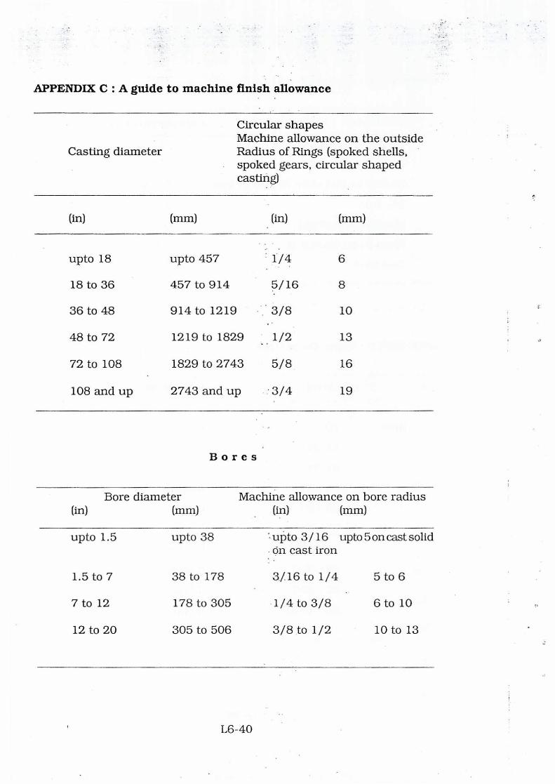
APPENDIX C : A guide to machine finish allowance
Casting diameter
Circular shapes Machine allowance on the outside Radius of Rings (spoked shells, spoked gears, circular shaped casting)
(in) (mm) (in) (mm)
upto 18 upto 457 1/4 6
18 to 36 457 to 914 5/16 8
36 to 48 914 to 1219 3/8 10
48 to 72 1219 to 1829 1/2 13
72 to 108 1829 to 2743 5/8 16
108 and up 2743 and up 3/4 19
Bores
Bore diameter Machine allowance on bore radius (in) (mm) (in) (mm)
upto 1.5 upto 38 '. upto 3/16 upto 5 on cast solid On cast iron
1.5 to 7 38 to 178 3/16 to 1/4 5 to 6
7 to 12 178 to 305 •1/4 to 3/8 6 to 10
12 to 20 305 to 506 3/8 to 1/2 10 to 13
L6-40

Bores
Greater dimension (in) (mm)
Machine allowance (in) (mm)
upto 12 upto 305 upto 3/16 upto 5 on cast solid on cast iron
12 to 24 305 to 610 3/16 5
24 to 48 610 to 1220 1/4 6
48 to 96 1220 to 2438 3/8 10
98 and up 2438 and up 1/2 13
Recommended minimum wall thickness of cast metals
Wall thickness
Sand Casting : Grey iron 3 - 6
Malleable iron 3
Steel .... 5 - 13
Cu-alloy 2.5
Al-alloy 3 - 5
Mg-alloy ••.. 4
Permanent mould: Gray iron 5
Al-alloy 3
L6-41

PART - III
A. TESTING OF CASTINGS (General)
1. Objectives
o To determine the quality of a material before, during or after the
casting is over.
o To determine the mechanical properties such as strength, hardness,
ductility etc. after processing
o To check for flaws within a finished casting
o To assess the likely performance of the material in a particular
service condition.
2. Testing of castings can be divided into 2 groups (1) Destructive
Testing(DT), and (2) Non-destructive Testing(NDT).
Destructive Testing(DT)
Non-destructive TEsting(NDT)
Hardness
Tensile, Compressive shear
Torsion
Impact, Fatigue & Creep
In all these tests the sample
materials are physically damaged
or broken. These tests helps in
selection of mechanical properties
and indirectly assess the defects
to facilitate arriving at quality
standard specified by the buyer/
standards organisations-Indian or
International.
Liquid penetrant Testing(LPT)
Magnetic electrical or eddy current
Testing. ultrasonic, Sonic, Radio-
graphic etc.
In these tests the sample material
is not destroyed neither physically
nor property-wise, hence the name
NDT. These steps helps in detection
of flaws of defects within a processed
or finished casting/component/
L6-42

Advantages and limitations of DT & NDT
Any single test may not serve the purpose. Sometime a number of
tests are to be conducted simultaneously on a single component to arrive
at conclusions to decide the property requirements from the point under
design. Then any of the test methods are to be selected to meet the
requirements.
Advantages of DT
Advantages of NDT
Can be often directly and reliably
measure response to service conditions
Measurements are quantitative and
readily usable for design or stand-
ardization
Interpretation of results by a skilled
technical is not required
Can be done on production
items without any damage on
parts.
Tests conducted on individual
specimens no necessity of
waiting for calculation of
results.
Can be done 100% of pro-
duction or on representative
samples
Correlation between test results and
service behaviour is usually direct,
leaving little margin for disagreement
among observers
Can be used when variability
in DT is wide and unpredi-
table. Different tests can be
applied to the same sample
sequentially. The tests can be
repeated on parts in service
Cumulate effect of service
usage can be measured
directly. Test may reveal
failure mechanism also.
Equipment is portable for use
in field.
L6-43

Limitations of DT
Can be applied only to a sample
representing the population
Tested parts cannot be placed
in service.
Repeated tests of same item are
often an impossibility and different
tests need different sizes and shapes
of samples
Extensive testing is not justified
and may be prohibited with high
cast of material or fabrication
Cumulate effects can be measured
for different lengths of time.
Difficult to apply to parts in service
and terminates the useful life after
testing
Extensive machining or other
preparation of test specimens is
often required.
Capital investment and manpower
costs are often high.
Limitation of NDT
Results often must be interpreted
by a skilled and experienced
Technician.
In absence of proven correlation
different observers may disagree on
meaning and significance of test
results
Properties are measured indirectly
and often only qualitative and compa-
rative measurements can be made
Some NDT (e.g. X-ray) require large
capital investments
L6-44

B. PROCESS CONTROL TESTS
Melt and quality tests
The most common methods of testing in process used in foundries
today include
- Temperature
- Thermal analysiS
- Chill
- Fluidity
- Chemical analysis
- Gas testing
To what extent any of these techniques are used depends upon a
variety of factors viz.
- Charge materials
Nature of final casting
- Moulding Method
- Type of metal
- and a host of other conditions like other testing methods
Strict documentation should accompany any inprocess testing to
allow for pin-pointing the cause of casting defects and preventing from
further occurrences.
C. NON-DESTRUCTIVE TESTING FOR CAST IRON CASTINGS
Depending on degree of integrity required, the factors to be look into
for castings are :
- Surface quality
- Internal discontinuities
Casting imperfections
L6-45