l50t/70 - l50/08 sheeters -...
TRANSCRIPT

L50T/70 - L50/08 SHEETERS
L50T/70 SHEETER
L50/80 SHEETER
THE MACHINE MUST NOT BE CONNECTED TO THE ELECTRIC SUPPLY IF THE WORK TABLES ARE NOT FITTED.
OPERATING MANUAL
234814-1

2
Before using the machine, read the instructions of this manual in order to ensure your safety and for instructions on how to use the machine. If you are unsure of any aspect of the installation, instructions or performance of your appliance, contact your CRAFTSMAN dealer promptly specifying the model and the serial number of this appliance.
1. Do not operate this appliance whilst under the influence of alcohol, medicines or drugs which could alter your physical condition.
2. Keep hair, loose clothing and other parts of the body away from rotating parts such as belts and gears. 3. Keep the warning signs, symbols and safety data notices clean and in order. GRAPHIC SYMBOLS USED IN THE MANUAL
Warnings regarding the execution of the operations described or possible danger. Operations that have to be performed only by authorized operators
Operations that can be performed by the machine operators, as they do not require specific qualifications.
PLATES
WARNING
Technical Data Plate showing manufacturing details, power rating, weight and conformity to the regulatory authority.
Electric Power Earth connection
Warning Signs signalling danger or specific prohibited operations.

3
INDEX INSTRUCTIONS - WARNING SYMBOLS – TECHNICAL DATA PLATE PAGE. 2
ADDRESSES - NOISE LEVEL - CORRECT AND INCORRECT USE - POSSIBLE RISKS PAGE. 3
TECHNICAL DATA – RECEIPT - ELECTRICAL CONNECTIONS PAGE. 4
CONTROL PANEL - DESCRIPTION OF THE MACHINE PAGE. 5
INITIAL STARTING AND TESTING – SAFE & CORRECT USE – MANUAL CYCLE PAGE. 6
CLEANING – MAINTENANCE PAGE. 7
FAULT FINDING - MACHINE STRUCTURE PAGE. 8
WIRING SCHEMATICS PAGE. 9
ELECTRICAL PARTS LIST PAGE. 10
AGENT SERVICE PROVIDER
NOISE LEVEL The average noise level near the working place is less than 70 decibel CORRECT AND INCORRECT USE The machine has to be used by competent operators and is to be located away from places accessible to everybody. It is forbidden to use the machine for any other purpose other than for use in producing baking products for bread.
POSSIBLE RISKS The machine has been manufactured to conform with the CEI safety regulations. Using the machine in any way other than stipulated by the manufacture may cause unpredictable risks. It is forbidden to alter mechanical or electrical components and parts, to change the internal and external structure of the machine, or to modify the appliance in any way.
The appliance is not to be operated without all the covers, protective guards and panels being in place and all the safety devices and microswitches in proper working order.
SERIAL NUMBER PURCHASE DATE
NAME OF THE PURCHASE ADDRESS

4
TECHNICAL DATA CRAFTSMAN L50T/70 and L50/08
CONFORMITY TO THE REGULATIONS The electric system conforms with EN 60204-1. The materials which are in contact with the dough conform with FDA rules. The machine has been certified in conformity with the Directive Machines 89/392/CEE and following modifications 91/368/CEE-93/44/CEE-93/68/CEE.
SAFETY DEVICES This appliance is fitted with two safety guards which stop the appliance when lifted. A red emergency push-button with a yellow ring is also fitted within easy reach of the operator.
LIFTING AND MOVING The appliance must only be lifted by authorized operators.
The appliance can be delivered packed in a wooden crate or in a wood pallet with cardboard packaging. When the appliance is delivered in a wooden crate, it can be lifted with a forklift or transpallet, or using a crane and lifting strops. In this case the tension max angle of strops is 45˚. This should not be exceeded. Once unpacked, the appliance can be lifted using a crane. RECEIPT The appliance packaging permits storing of the appliance, under cover, for up to one year. When unpacking, check the appliance and supplied parts for damage. Report any damage to the carrier and distributor. Report any deficiencies to the distributor immediately. LEVELLING Position the appliance in it’s working position and ensure that the appliance is levelled and that adjustable castors / feet are correctly fitted and adjusted. Leave enough space around the machine for the operator to carry out his tasks and for maintenance operations. Do not place the appliance near heat sources. ELECTRICAL CONNECTIONS
All electrical connection must be carried out by a suitably qualified person.
Check that the electrical supply is correct to as shown on the Technical Data Plate fitted to the appliance. The electric supply is fed through an all pole disconnection switch rated for this appliance using 3 phase, 4 pin plug (3 phase + earth) as required. All electrical connections must conform with the regulations in force in the Country where the appliance is to be used.
Belt Dimensions 500 x 900/1200
Sheeting Speed Exit Belt 25 M/min
Roller Length 495 mm
Rollers Diameter. 60 mm
Roller Gap Setting 38 mm
Installed Power 0.55 Kw
Weight 170 Kg
Structure Steel enamelled
500 x 700
25 M/min
495 mm
60 mm
38 mm
0.55 Kw
138 Kg
Steel
L50T/70 L50/08

5
CONTROL PANEL The buttons on the appliance control panel are as shown in the picture opposite: 1. EMERGENCY STOP PUSH BUTTON.
2. START PUSH BUTTON.
3. FEED CONTROL SWITCH. DESCRIPTION OF THE MACHINE This appliance can be used to sheet all kinds of pastry dough, puff-pastry, leavened pastry, neapolitan puff-pastry etc. The sheeter works quickly and silently and it is fitted with variable speed conveyor belts. Two levers on the side panel of the head, control the direction of rotation for the belts. The dough thickness can be adjusted by a lever. The appliance is also fitted with 2 safety guards that stop the appliance if any of the safety guards are raised. The structure of the appliance is made of electro welded steel plate, the sheeting rollers are chromium plated and the scrapers are coated with anti-adherent teflon. WORK TABLE ASSEMBLY
The following operation must be performed by authorized persons The appliance must not be connected to the mains electrical supply, before fitting or removing the tables.
The working tables must be fitted to the sheeter before operating the appliance. To fit the working tables, push the cylinder pin inside the journal bearing; if necessary adjust the belt for the correct tension. To remove the working-tables, push the table to the opposite side of the machine and remove. The tables are not interchangeable. EXTERNAL PARTS OF THE MACHINE CONTROL PUSH-BUTTONS SAFETY GUARDS Once any one of the safety guards are lifted, a safety microswitch will stop the sheeter. CONVEYOR BELT DIRECTION CHANGING LEVER The joy stick 1 allows the operator to change the direction of the conveyor belt rotation. ROLLER GAP ADJUSTMENT LEVER Move the lever to the right to get the minimum roller opening. Move the lever to the left to move the rollers to their maximum opening position. Use knob 2 to set the position of the lever. SCRAPERS The upper and lower scrapers are hinged and are kept in contact with the cylinder by means of springs and a locking device. The scrapers are easily removed.
1 2
3
BELT TENSION ADJUSTING SCREW
1
2
6
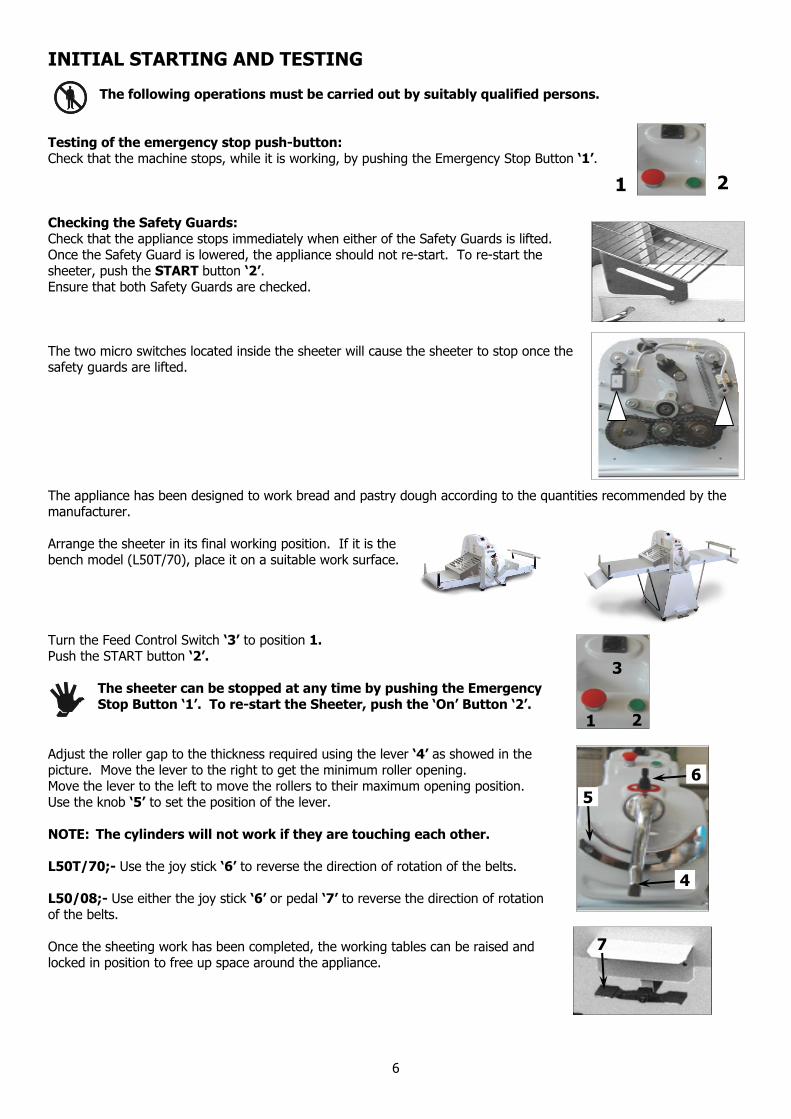
INITIAL STARTING AND TESTING The following operations must be carried out by suitably qualified persons.
Testing of the emergency stop push-button: Check that the machine stops, while it is working, by pushing the Emergency Stop Button ‘1’. Checking the Safety Guards: Check that the appliance stops immediately when either of the Safety Guards is lifted. Once the Safety Guard is lowered, the appliance should not re-start. To re-start the sheeter, push the START button ‘2’. Ensure that both Safety Guards are checked. The two micro switches located inside the sheeter will cause the sheeter to stop once the safety guards are lifted. The appliance has been designed to work bread and pastry dough according to the quantities recommended by the manufacturer. Arrange the sheeter in its final working position. If it is the bench model (L50T/70), place it on a suitable work surface. Turn the Feed Control Switch ‘3’ to position 1. Push the START button ‘2’.
The sheeter can be stopped at any time by pushing the Emergency Stop Button ‘1’. To re-start the Sheeter, push the ‘On’ Button ‘2’.
Adjust the roller gap to the thickness required using the lever ‘4’ as showed in the picture. Move the lever to the right to get the minimum roller opening. Move the lever to the left to move the rollers to their maximum opening position. Use the knob ‘5’ to set the position of the lever. NOTE: The cylinders will not work if they are touching each other. L50T/70;- Use the joy stick ‘6’ to reverse the direction of rotation of the belts. L50/08;- Use either the joy stick ‘6’ or pedal ‘7’ to reverse the direction of rotation of the belts. Once the sheeting work has been completed, the working tables can be raised and locked in position to free up space around the appliance.
1 2
3
2 1
4
5 6
7

7
CLEANING THE SHEETER
ALWAYS ENSURE THAT THE APPLIANCE IS ISOLATED FROM THE MAINS SUPPLY BEFORE COMMENCING ANY CLEANING OPERATIONS
Any dough, which may have stuck on the cylinders, must not be removed whilst the sheeter is operating.
At the end of every working day, clean the scrapers and the conveyor belts, using a plastic scraper to remove build up of hard deposits. Do Not use water jets to clean this sheeter. The scrapers can be removed by unhooking the springs or using the knobs.
MAINTENANCE OF THE SHEETERS During maintenance operations the sheeter must not be connected to the mains electrical supply. The replacement of parts and any repair to the electric system, must only be carried out by suitably qualified persons. If the sheeter is within warranty period, inform the manufacturer.
ELECTRIC PANEL The fuses in the picture opposite are identified with the code ‘FU’ FU1 = Transformer (2F) protection fuse. FU2 = Printed Circuit Board (F4) protection fuse. A copy of the Wiring Diagram is placed in the sheeter electrical compartment.
BELT TENSIONING TENSIONING THE MOTOR DRIVE BELT TENSIONING THE CHAIN
The tension of the belt can be adjusted using the screw shown in the picture.
Remove the back panel. Check the belt tensioning. If required adjust the nuts as shown in the picture, to tension the belt.
Remove the back panel. Check the chain tension. If required, adjust the nut as shown to tension the belt.

8
FAULT FINDING THE MOTOR AND SAFETY SYSTEM Call for Service.
POSSIBLE DEFECTS AND SOLUTIONS
SCRAPPING THE MACHINE The structure of the machine is made in stainless steel or plate enamelled with powder enamel or two parts enamel. The belts are made of synthetic rubber, the cylinders, the safety guards and the cylinder position controls are made in steel chromed or in stainless steel AISI 304. The electrical components and the scrapers are made of plastic material.
ENCLOSURES. With the manual we include a wiring diagram (One copy is placed in the sheeter electrical compartment).
DEFECT CAUSE SOLUTION The machine doesn’t start. The lever micro switches are not energised. Check the microswitch adjustment.
The machine doesn’t start. The safety guard is not completely lowered. Check the safety guard and the microswitches.
The belts are slipping. The belts are not tensioned correctly. Check the belt tension and correctly tension.

9
Wiring Schematic Craftsman Sheeters
L50T-70
L50-08 230 / 400 V 50/60 Hz
Power 0,75 kw

10
L50T/70 - L50/08 SHEETERS
Electrical Parts List
CODE DESCRIPTION PRODUCER MODEL QTY Box GEWISS GW 44.207 1 QS1 Main Switch BREMAS A1203 PL1 1 TC Transformer 8VA 0.230.400/0.24 TEFMA TF223 1 FU1 Fuse Holder OMEGA PZ1005 2 Transformer Fuses OMEGA 6,3 x 30 2A GL 2 FU2 Auxiliary Fuse Holder OMEGA C1033 1 230V Auxiliary Fuses OMEGA 5 x 20 6A F 2 400V Auxiliary Fuses OMEGA 5 x 20 4A F 2 KM1-KM2 Teleinverter A.B.B. VB6A3001P24VAC 1 KA1 Auxiliary Relay FINDER 40.52. 24VAC 1 Printed Circuit DAL PONTE E9816/A LC 1 SQ1 Cover Limit Switch TELEMECANIQUE XCXB102 1 SQ2 Cover Limit Switch TELEMECANIQUE XCXB102 1 Manipulator GE P9MMN2F 1 SB3 Manipulator Contact GE P981OVN 1 SB4 Manipulator Contact GE P981OVN 1 SQ5 Reverse Limit Switch TELEMECANIQUE XCKB102 1 SQ6 Reverse Limit Switch TELEMECANIQUE XCKB102 1 SB1 Emergency Stop Button ABB K2056 9 KZ 494 2 1 SB2 Start Button ABB EP305 5 KZ 492 6 1 Power Connecting Terminal 3 Pole PHOENIX GMKDS 3/3 2 Auxiliary Connecting Terminal 4 Pole PHOENIX MKDSN 2,5/4 4 Auxiliary Connecting Terminal 3 Pole PHOENIX MKDSN 2,5/3 1 Faston OMEGA CC342 3 Nylon Press Cable OELMA PG11 MAXIBLOCK 1 Nylon Nut OELMA PG11 1 Nylon Press Cable OELMA 3/8 GAS 3 Nylon Nut OELMA 3/8 GAS 3 Nylon Press Cable OELMA 1/4 GAS 6 Nylon Nut OELMA 1/4 GAS 6 230v Plug ILME PE1694SV 1 400v Plug ILME PE1664SV 1
