l3 milestone - light water reactor … aging and degradation/l3_milestone... · quantification of...
TRANSCRIPT
1
L3 Milestone -
September 2016 Zhili Feng, Nesrin Cetiner, Xunxiang Hu and Roger Miller, ORNL
Greg Frederick, Benjamin Sutton EPRI Overview Welding is widely used for repair, maintenance and upgrade of nuclear reactor components. As a critical mitigation technology to extend the service life of nuclear power plants beyond 60 years, weld technology must be further developed to avoid and/or reduce the detrimental effect associated with the traditional welding fabrication practices, as well as for the ability to repair of highly irradiated materials. As nuclear power plants age, the extent and level of radiation damage will increase, as does the demand of welding repair and mitigation of irradiated structural internals. This research is a joint DOE/LWRSP (Light Water Reactor Sustainability Program) and EPRI/LTO (Long Term Operability) effort aimed at developing advanced welding technology for reactor repair and upgrade. It focuses on welding repair of irradiated materials that are extremely challenging and requires long-term R&D. The technology development is also expected to have broad benefit. For example, the proactive stress management and friction stir welding technology can improve the resistance to stress corrosion cracking. The advanced welding simulation tool would provide more reliable prediction of the weld residual stress for component integrity analysis and risk assessment. The DOE LWRSP portion of the project will focus on the fundamental science aspect of the project, whereas the EPRI/LTO part will focus on the welding system and process development. This milestone was directed toward continued production helium-containing materials representative of those expected in a nuclear power plant reactor internals at extended service times, through neutron irradiation at HFIR facility of Oak Ridge National Laboratory. The materials being irradiated for welding research include austenitic stainless steel alloys SS304 and SS316 that are used for construction and Alloy 182. Alloy 182 is a common weld filler metal used for dissimilar metal weld joints between austenitic stainless steel and either ferritic or other austenitic metals. These materials will be used in the experimental validation of the planned repair welding technology development. The helium bubble distribution within the materials will be investigated through TEM. The quantification of generated helium resulting from transmutation reactions will be carried out by using the Thermal Desorption Spectrometry (TDS) system at the Low Activation Materials Development and Analysis (LAMDA) laboratory of ORNL. The complete release of helium requires melting the studied materials, which could not be realized by using the current heater of the TDS system with a maximum temperature of 1150°C. Therefore, upgrading the heater has been planned to reach a maximum temperature of 1650°C, high enough to melt the SS304, SS316 or Alloy 182.
2
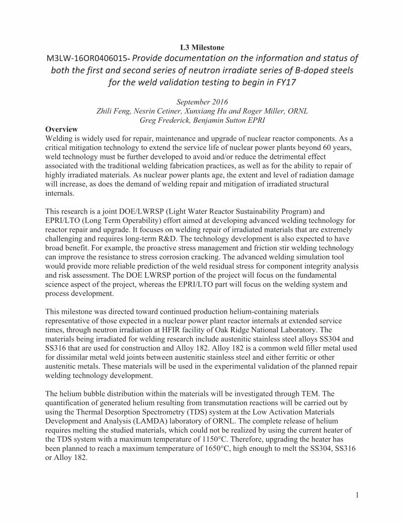
The first irradiation campaign was completed in June 2014 and the specimens are stored at HFIR to allow for activity decay. Several specimens have been shipped to 3025E for examination and removal of specimens for helium distribution. The second irradiation campaign will be composed of SS304, SS316 and Alloy182 specimens for three HFIR cycles and is planned to begin in November 2016 with Fuel Cycle 469. This effort has been cost-shared with EPRI, which funded the production of stainless steels and nickel superalloys with different level of Boron concentrations that will undergo transmutation into helium during irradiation. Producing Boron Containing Alloys Repair welding on highly irradiated helium-containing materials can lead to cracking in the heat-affected zone (HAZ) of the weld region. Studies in the past have established that such cracking is attributed to the presence of entrapped helium in the post-irradiated material. Helium forms by transmutation of boron and nickel into alpha particles under neutron irradiation, as illustrated in Figure 1(a). Helium is essentially insoluble in metals. It is therefore thermodynamically favorable for the entrapped helium to precipitate to form bubbles/microvoids/cavities along grain boundaries. Helium bubbles nucleate, grow and coalesce rapidly at grain boundaries under the combined actions of high temperature and tensile stresses, which occur during the welding process. Intergranular rupture occurs as the cohesive strength of the grain boundary (weakened by helium bubbles) can no longer bear the shrinkage-induced internal tensile stress during cooling of the weld. Cracks form primarily in the HAZ, generally less than a millimeter from the fusion boundary. An example of helium induced weld cracking is shown in Figure 1(b).
Figure 1. (a) Formation of helium due to transmutation of B and Ni from neutron irradiation. (b) Helium induced cracking in a TIG weld of stainless steel SUS304 (after Asano et al, (1999) J. Nuclear Materials, 264:1-9)
As shown in Figure 2, as the nuclear power plants continue to operate beyond their initial design lives, the amount of helium in the structural internals of a reactor is expected to reach to a level that cannot be repaired or becomes very difficult by today’s welding repair technologies. The objective of this milestone is to produce custom made alloys representative of nuclear reactor structural internals (SS304, SS316, Alloy 182) at helium levels targeted for 50, 60 and 70 years of operation for reactor internals.

3
Figure 2. Forecast of Helium Generation at 75 wppm Boron at 60 EFPY (Typical CE PWR). Red Zone: >10 appm He (not weldable with current welding processes); Yellow Zone: 0.1 to 10 appm He (weldable with heat input control during welding repair); Green Zone: <0.1 appm He (No special process control is needed in welding repair) (EPRI BWRVIP-97A)
The production of the helium containing materials consisted of (1) producing custom made alloys of precisely controlled chemistries with controlled additions of boron at several target levels, and (2) irradiating the boron containing alloys with neutrons to transmute boron (and a small amount of Ni) to helium. Such an elaborate strategy, although expensive, was essential to produce alloys closely subjecting to the helium generation processes in a nuclear rector necessary for the planned welding repair study. The two stainless steels alloys (SS304 and SS316) were produced at ORNL. Five heats of each alloy were doped with natural occurring boron at five different concentration levels (nominally 0, 5, 10, 20 and 30 ppm boron by weight) and casted by Vacuum Arc Remelting (VAR). The ingots were homogenized at 1050°C for 5 hours in air and then hot rolled to 19 mm thick, followed with

4
cold rolling to 12 mm thick (about 35% reduction) to produce rectangular bar stock. A solution heat treatment (1000°C for 30 minutes for SS304 and 1050°C for 30 minutes for SS316 followed by water quenching) was then applied to produce acceptable microstructure. Metallographic characterization confirmed that both alloys had satisfactory grain size (less than 100 micron), absence of grain boundary carbides, and acceptable ferrite and martensite levels. The bar stock were machined to final dimensions (76x56x8.9mm nominal) to yield 6-8 pieces at each boron level for subsequent irradiation. Table 1 shows the complete chemistry analysis results of the ten heats of stainless steel made in this project. As shown in the table, the target boron concentrations were achieved. Furthermore, Co concentrations in all samples were extremely low, in the range of 60-80 ppm by weight. It was done deliberately through an exhaustive search of low Co master alloys used in the VAR process. The Co concentrations were kept as low as practically possible, in order to minimize the radiation level of the specimens to ease the handling and analysis of irradiated materials during the repair welding experiment and post welding analysis and characterization. Elements listed in ppm units were analyzed by Glow Discharge Mass Spectrometry while elements listed by weight percent (wt%) were analyzed by Optical Emission Spectrometry (OES) with the exception of C (Leco Combustion) and N (Gas Fusion). Elements listed twice were analyzed by both methods. Five heats of Alloy 182 with five boron target concentration levels (nominally 0, 5, 10, 20, and 30 ppm boron by weight) were produced by Sophisticated Alloys, Inc. following specifications provided by ORNL. Table 2 shows the complete chemistry analysis of the Alloys 182 heats made in this project. As shown in the Table 2 not all of the target boron concentrations were achieved but a wide range of boron levels were produced ranging from 0.3 to 23 ppm. All other elements met the chemistry requirements for Alloy 182. As with the stainless steel, the Co concentrations were kept as low as practically possible, in order to minimize the radiation level of the specimens to ease the handling and analysis of irradiated materials during the repair welding experiment and post welding analysis and characterization. Bar stock sections machined to final dimensions (76x56x8.9mm nominal) to yield 7 pieces at each boron level for subsequent irradiation. These thirty-five specimens have a wrought microstructure similar to the stainless steel specimens. Alloy 182, being weld filler metal, typically has a coarser weld microstructure in reactor structures. An additional fifteen specimens from heats 182D and 182E respectively were fusion welded on one side to half of the specimen depth to produce a representative weld microstructure.

5
Table 1 Chemistry Analysis Results of SS304 and SS316
Stainless Steel Heat Identification Element Unit 304A 304B 304C 304D 304E 316A 316B 316C 316D 316E
B ppm 0.8 4.8 10 24 32 0.9 4.7 12 22 30 Co ppm 77 79 79 75 76 68 70 64 69 65 Al ppm 5 5 4 10 5 4 5 6 4 4 P ppm 18 19 19 18 18 16 17 28 16 14 S ppm 14 14 14 15 14 14 14 23 14 13
Mo ppm 390 220 180 240 180 Cu ppm 600 590 610 590 600 530 540 570 530 520
C wt.% 0.012 0.007 0.014 0.01 0.012 0.012 0.012 0.014 0.007 0.009
Mn wt.% 1.54 1.55 1.5 1.53 1.52 1.4 1.39 1.39 1.42 1.39 Si wt.% 0.49 0.5 0.49 0.49 0.48 0.44 0.43 0.43 0.44 0.42 P wt.% <0.001 <0.001 <0.001 <0.001 <0.001 <0.001 <0.001 0.001 <0.001 <0.001 S wt.% 0.002 0.003 0.002 0.002 0.002 0.002 0.002 0.004 0.001 0.002 Cr wt.% 19.53 19.54 19.28 19.33 19.14 17.81 17.63 17.42 17.57 17.38 Ni wt.% 10.61 10.52 10.35 10.41 10.25 12.08 11.82 11.83 11.88 11.92 Mo wt.% 0.05 0.04 0.04 0.04 0.04 2.54 2.41 2.65 2.51 2.72 Cu wt.% 0.05 0.05 0.05 0.05 0.05 0.05 0.05 0.06 0.06 N wt.% 0.035 0.032 0.035 0.035 0.035 0.03 0.03 0.034 0.031 0.03 Fe Balance Balance Balance Balance Balance Balance Balance Balance Balance Balance
Table 2 Chemistry Analysis Results of Alloy 182
Alloy 182 Heat Identification Element Unit 182A 182B 182C 182D 182E
B ppm 0.3 5 15 14 23
Co ppm 2 2 2 2 2 Al ppm 81 34 32 54 56 Mo ppm 1 1 8 1 1 Cu ppm 2 1 2 1 1
C wt% 0.03 0.08 0.03 0.04 0.04
Mn wt% 7.03 7.00 6.76 7.17 7.08 Si wt% 0.50 0.50 0.51 0.50 0.49 Cr wt% 15.99 16.00 16.00 16.16 16.10 Fe wt% 7.36 7.92 7.31 7.14 7.12 Nb wt% 2.07 2.06 1.83 1.82 1.84 Ti wt% 0.44 0.43 0.43 0.43 0.46 P wt% 0.00013 0.00011 0.00018 0.00015 0.00016 S wt% 0.00207 0.00199 0.00280 0.00200 0.00220 Ni Balance Balance Balance Balance Balance
6
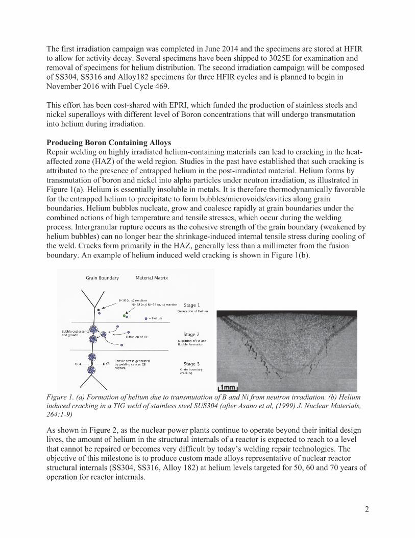
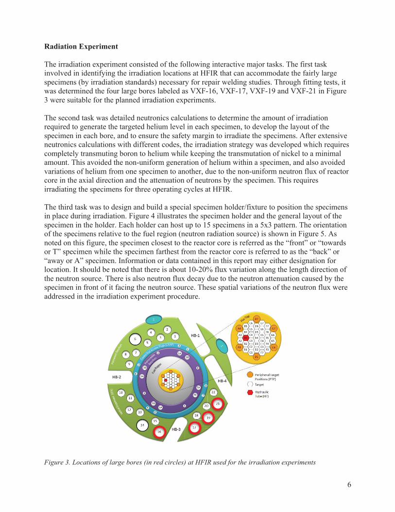
Radiation Experiment The irradiation experiment consisted of the following interactive major tasks. The first task involved in identifying the irradiation locations at HFIR that can accommodate the fairly large specimens (by irradiation standards) necessary for repair welding studies. Through fitting tests, it was determined the four large bores labeled as VXF-16, VXF-17, VXF-19 and VXF-21 in Figure 3 were suitable for the planned irradiation experiments. The second task was detailed neutronics calculations to determine the amount of irradiation required to generate the targeted helium level in each specimen, to develop the layout of the specimen in each bore, and to ensure the safety margin to irradiate the specimens. After extensive neutronics calculations with different codes, the irradiation strategy was developed which requires completely transmuting boron to helium while keeping the transmutation of nickel to a minimal amount. This avoided the non-uniform generation of helium within a specimen, and also avoided variations of helium from one specimen to another, due to the non-uniform neutron flux of reactor core in the axial direction and the attenuation of neutrons by the specimen. This requires irradiating the specimens for three operating cycles at HFIR. The third task was to design and build a special specimen holder/fixture to position the specimens in place during irradiation. Figure 4 illustrates the specimen holder and the general layout of the specimen in the holder. Each holder can host up to 15 specimens in a 5x3 pattern. The orientation of the specimens relative to the fuel region (neutron radiation source) is shown in Figure 5. As noted on this figure, the specimen closest to the reactor core is referred as the “front” or “towards or T” specimen while the specimen farthest from the reactor core is referred to as the “back” or “away or A” specimen. Information or data contained in this report may either designation for location. It should be noted that there is about 10-20% flux variation along the length direction of the neutron source. There is also neutron flux decay due to the neutron attenuation caused by the specimen in front of it facing the neutron source. These spatial variations of the neutron flux were addressed in the irradiation experiment procedure.
Figure 3. Locations of large bores (in red circles) at HFIR used for the irradiation experiments

7
Figure 4. CAD drawings of the sample holder for irradiation. Top: detailed view showing three specimens stacking in the thickness direction. Bottom: a total of 15 (5x3) specimens loaded in the sample holder. Five specimens stacked along the length direction of the holder
1 2 3
13-15
10-12
7-9
4-6
1-3
8
Figure 5. Orientation of the specimens relative to the fuel region and neutron irradiation
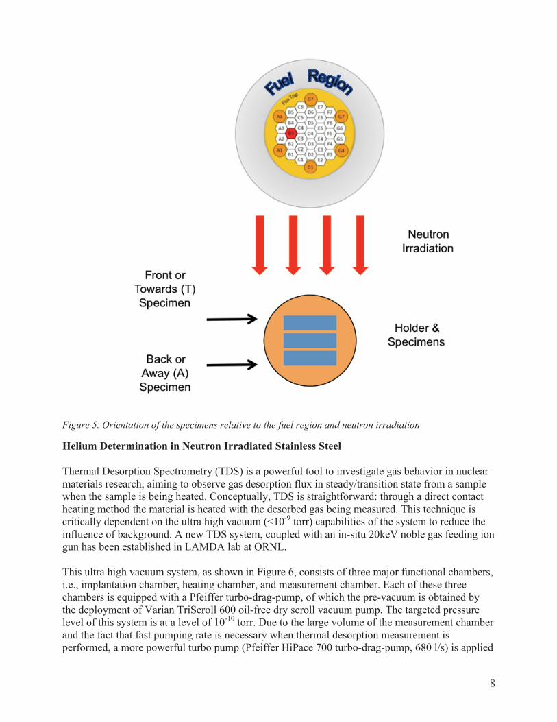
Helium Determination in Neutron Irradiated Stainless Steel Thermal Desorption Spectrometry (TDS) is a powerful tool to investigate gas behavior in nuclear materials research, aiming to observe gas desorption flux in steady/transition state from a sample when the sample is being heated. Conceptually, TDS is straightforward: through a direct contact heating method the material is heated with the desorbed gas being measured. This technique is critically dependent on the ultra high vacuum (<10-9 torr) capabilities of the system to reduce the influence of background. A new TDS system, coupled with an in-situ 20keV noble gas feeding ion gun has been established in LAMDA lab at ORNL. This ultra high vacuum system, as shown in Figure 6, consists of three major functional chambers, i.e., implantation chamber, heating chamber, and measurement chamber. Each of these three chambers is equipped with a Pfeiffer turbo-drag-pump, of which the pre-vacuum is obtained by the deployment of Varian TriScroll 600 oil-free dry scroll vacuum pump. The targeted pressure level of this system is at a level of 10-10 torr. Due to the large volume of the measurement chamber and the fact that fast pumping rate is necessary when thermal desorption measurement is performed, a more powerful turbo pump (Pfeiffer HiPace 700 turbo-drag-pump, 680 l/s) is applied

9
for the measurement chamber. The other two chambers are pumped by using Pferiffer HiPace 80 turbo-drag-pumps (71 l/s). Three MKS 909AR digital and analog hot cathode vacuum transducers monitor the pressure levels of the chambers.
Figure 6. The gas implantation and thermal desorption system in LAMDA lab at ORNL After being placed in the tungsten crucible, the sample will be transported by a MDC special precision magnetically coupled transporter, mounted onto a Dual Axis XY stage, from implantation chamber to heating chamber by passing through the connecting vacuum channel. The current electrical resistivity heater was designed and manufactured by HeatWave Labs, with a maximum temperature of 1150°C.

10
Helium detection in the TDS is preformed by using a Pfeiffer HiQuad quadruple mass spectrometer equipped with a Channeltron type electron multiplier. A linear relationship exists between ion current in the mass spectrometer and helium partial pressure:
)()( torrPAI He∝ . (1) The helium desorption rate from a sample is described by:
τ)()()()()( tP
dttdPtP
VS
dttdP
dtdNtL +=+== , (2)
Where L(t) is the helium desorption rate, N is the number of helium atoms, P(t) is the partial pressure of helium, S is the pumping speed (L s-1), V is the chamber volume (L), and τ = V/S, the pumping time constant (s). The TDS system can operate in two modes, either static or a dynamic mode. In the static mode, the τ
)(tP term in Eq. (2) is minimized, with no pumping on the measurement chamber. In the
dynamic mode, the dttdP )( term in Eq. (2) is minimized, and τ is adjusted by the valve to the
turbo-drag pump. This system operates in the dynamic mode. The mass spectrometer will be calibrated by a standard helium leak to determine a calibration factor:
IatomsHeQ #= (3)
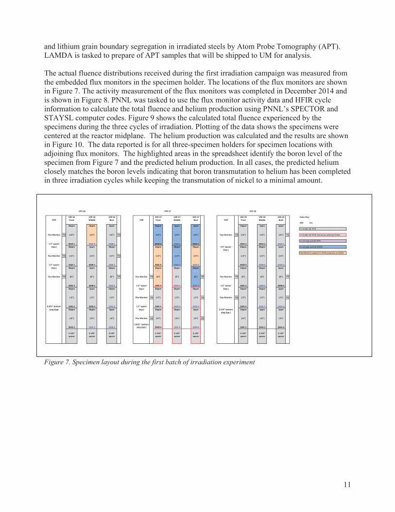
Then the desorbed helium amount could be determined. Status The first irradiation campaign with 45 stainless steel specimens (23 SS304 and 22 SS316) with different boron levels has been completed. The irradiation experiment spanned over three HFIR operation cycles (Cycles 451, 452 and 453) from January 14, 2014 to May 30, 2014. Three specimen holders were used to load the specimens each into VXF-16, VXF-17 and VXF-19. Each specimen holds a total of 15 specimens in 5x3 pattern. The actual layout of the specimen and the position of each specimen during the irradiation experiment were recorded and are provided in Figure 7. The spacers in the bottom of the holders centered the specimens at the reactor midplane. The current location of irradiated specimens is also shown in Figure 7. A number of irradiated specimens have been shipped to 3025E for initial PIE in order to determine if the specimens require any additional processing prior to welding in the welding cubicle in 7930 Hot Cell C. Small sections of several specimens have been removed in order to conduct helium content and distribution measurements in LAMDA by TDS and TEM and to support a Rapid Turnaround PIE for the University of Michigan (UM). The UM study will investigate the boron
11
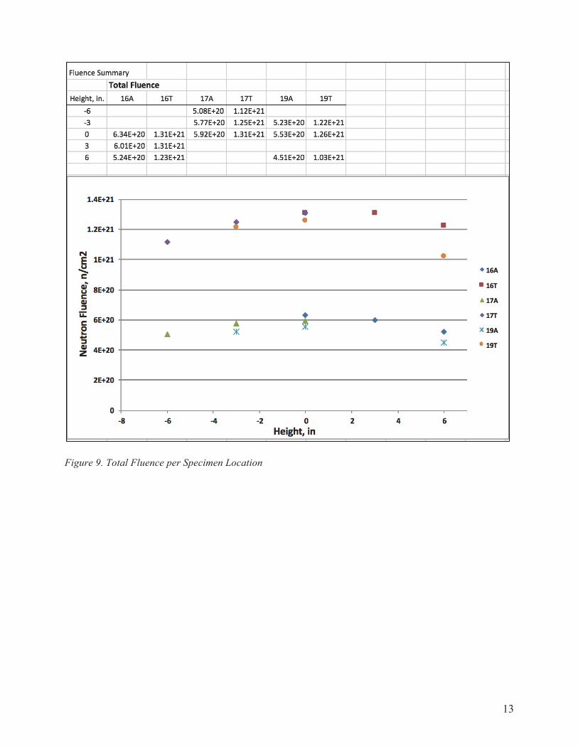
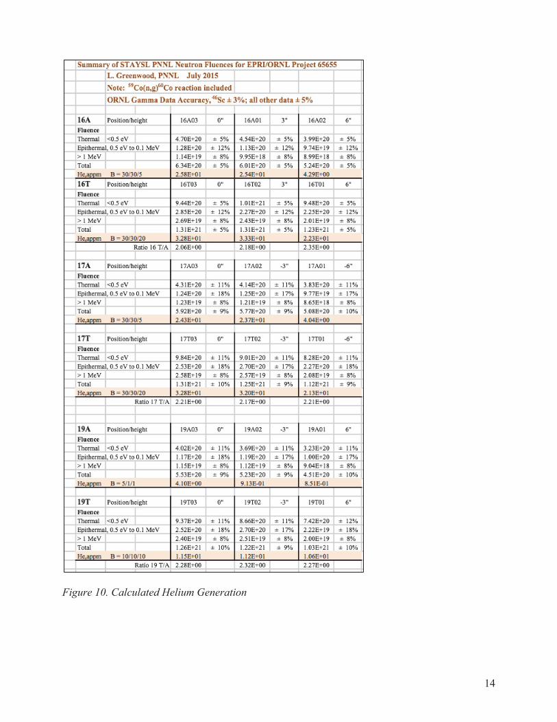
and lithium grain boundary segregation in irradiated steels by Atom Probe Tomography (APT). LAMDA is tasked to prepare of APT samples that will be shipped to UM for analysis. The actual fluence distributions received during the first irradiation campaign was measured from the embedded flux monitors in the specimen holder. The locations of the flux monitors are shown in Figure 7. The activity measurement of the flux monitors was completed in December 2014 and is shown in Figure 8. PNNL was tasked to use the flux monitor activity data and HFIR cycle information to calculate the total fluence and helium production using PNNL’s SPECTOR and STAYSL computer codes. Figure 9 shows the calculated total fluence experienced by the specimens during the three cycles of irradiation. Plotting of the data shows the specimens were centered at the reactor midplane. The helium production was calculated and the results are shown in Figure 10. The data reported is for all three-specimen holders for specimen locations with adjoining flux monitors. The highlighted areas in the spreadsheet identify the boron level of the specimen from Figure 7 and the predicted helium production. In all cases, the predicted helium closely matches the boron levels indicating that boron transmutation to helium has been completed in three irradiation cycles while keeping the transmutation of nickel to a minimal amount.
Figure 7. Specimen layout during the first batch of irradiation experiment

12
Figure 8. Flux Monitor Activity Measurements
13
Figure 9. Total Fluence per Specimen Location
14
Figure 10. Calculated Helium Generation
15
Future Work A second irradiation campaign is being prepared. The specimen holders have been slightly redesigned to allow easier specimen removal after irradiation. Dimensional and chemical analysis of all potential specimens is available. Four specimen holders are currently in machining and after inspection will be available for loading. Three holders will be loaded for irradiation with the remaining holder reserved as a spare and used for future irradiations. Specimens have been selected and consist of five SS304, seven SS326, twenty Alloy 182 with wrought microstructure and thirteen Alloy 182 with weld microstructure specimens. Flux monitors will not be used in the upcoming campaign due to the results achieved in the first irradiation campaign. The current plan is to begin irradiation of the second campaign with HFIR Cycle 469 that begins in November 2016 and last for three HFIR fuel cycles. Finally, measurement of actual helium concentration and distribution within each irradiated specimen is planned as well. Small pieces will be cut from a specimen for helium measurement by TDS and helium distribution by TEM. The current TDS system in LAMDA cannot reach sufficient temperatures to melt the sample and the system is going through an upgrade to allow melting of stainless steel or Alloy 182. The measurement schedule has yet to be finalized, which will be dependent on the radioactivity measurement of the specimens in 3025E and the TDS upgrade. The design of the new TDS heater has been completed and is being fabricated by Materials Research Furnaces Inc. Based on the contract; it is expected to be delivered by the end of September in 2016. Figure 11 shows the schematic plot of this customized heater. The W heating element is used to build the hot zone, where a W crucible support bar is inserted. To improve the heating efficiency, W and Mo radiation shields surrounding the work area and the heating element are applied. The open window on the shields provides access for loading and unloading the crucible. Two Type C thermocouples (one control and one over-temperature protection) with direct access into hot zone are used. A 3kW rack mount DC power supply will be connected with the two water-cooled power feed through by the double insulated water-cooled power cables. One Eurotherm 3504 temperature programmable controller and one 3216 over-temperature limit controller will be used to control the temperature ramping process. In order to align with the heater upgrading, a new W crucible with a small cap, avoiding sputtering of molten materials, has been designed as shown in Figure 12. Midwest Tungsten Service is fabricating the new crucibles.

16
Figure 11. Schematic plot of the new heater together with the TDS measurement chamber
Figure 12. New W crucible with cap to fit the open access of the radiation shields.
To coordinate with the new heater, the utilities for the TDS system at LAMDA are being modified. 208V, 3 phase, 60 Hz power is needed and the water-cooling used for the heater requires 0.75 GPM flow with an inlet temperature of 70°F and 50 psi. The construction of the required utilizes are ongoing. Once the heater is received, it will be mounted to the TDS system for further testing with respect to temperature control, background check, and operating procedure.