l. stabilization of soil slopes
TRANSCRIPT
LChapter 17 ROBERT D. HOLTZ AND
ROBERT L. SCHUSTER
STABILIZATION OF SOIL SLOPES
1. INTRODUCTION
The basic principles for design and construc-tion of stable slopes in soils are quite well
known. The engineering properties of soils as they relate to slope stability are generally understood. Analysis capabilities for slope stability have im-proved markedly in recent years because of the digital computer. In this report Parts 2, Investi-gation, and 3, Strength and Stability Analysis, provide important background information for this chapter. Specifically, Chapter 12 (Soil Strength Properties and Their Measurement) gives the procedures for determination of the ap-propriate soil parameters utilized in the stability analyses that are discussed in detail in Chapter 13. In this chapter the basic principles established in Parts 2 and 3 are applied to the design of stable slopes for new construction of both excavated and embankment slopes. The procedures are also ap-propriate for the analysis of preconstructed slopes, as well as for design of remedial works and correc-tion of existing landslides.
This chapter is an update of Chapter 8 in Special Report 176 (Gedney and Weber 1978), which in turn built upon earlier reports (Baker and Marshall 1958; Root 1958). Because much of the basic tech-nical information given by Baker and Marshall, Root, and Gedney and Weber is still valid, empha-sis in this chapter will be on recent case histories and innovations in slope stabilization techniques since 1978.
2.DESIGN CONSIDERATIONS
Several factors are basic and must be considered in the design of stable slopes. First, because of the nature of soils and the geologic environments in which they are found, virtually every slope design problem is unique (Peck and Ireland 1953;Hutch-inson 1977). Second, the procedures used to esti-mate the stability of an excavated slope are the same as those used to estimate the stability of an embankment slope. These first two factors are true for the analysis of newly constructed slopes as well as for existing slopes and for the design of reme-dial measures. Third, designing a stable slope includes field investigations, laboratory tests, sta-bility analyses, and proper construction control. Because most of the details involved in this work cannot be standardized, good engineering judg-ment, experience, and intuition must be coupled with the best possible data gathering and analyti-cal techniques to achieve a safe and economical solution to slope stabilization.
3. FACTOR OF SAFETY
In conventional practice the stability of a slope is expressed in terms of its factor of safety, although in recent years there has been increasing interest in developing a probabilistic assessment of slope reliability (see Chapter 6). In the conventional approach, factors of safety less than 1 obviously indicate failure, or at least the potential for failure,
439
440
Landslides: Investigation and Mitigation
whereas stability is represented by safety factors greater than 1. The choice of the appropriate safety factor for a given slope depends on a number of considerations, such as the quality of the data used in the analysis, which in turn depends on the qual-ity of the subsurface investigations; laboratory and field testing; interpretation of field and laboratory data; quality of construction control; and, in some cases degree of completeness of information about the design problem. The engineer must also con-sider the probable consequences of failure. In most transportation situations, slope designs generally require safety factors in the range of 1.25 to 1.50. Higher factors may be required if slope movements have the potential for causing loss of human life or great economic loss or if there is considerable uncertainty regarding the pertinent design param-eters, construction quality control, potential for seismic activity, and so forth. Likewise, lower safety factors may be used if the engineer is confident of the accuracy of the input data and if good con-struction control may be relied upon.
4. DESIGN PROCEDURES AND APPROACH ES
Details of slope stability analysis procedures are given in Chapter 13. Analytical techniques allow a comparison of various design alternatives, includ-ing the effects of those alternatives on the stability, of the slope and on the economy of the possible solutions. In addition, all potential failure modes and surfaces should be considered. As discussed in Chapter 13, preliminary analyses may utilize sta-bility charts with simplified assumptions; such simple stability determinations may be adequate in many cases to decide whether a standard slope angle can be used. More involved analysis and sta-bility calculations may be necessary for more com-plex problems. In all cases, consideration must be appropriately taken of the environmental condi-tions to which the slope is likely to be subjected during its entire design life, including changes in soil strength and groundwater conditions, possible seismic activity, or other environmental factors. As a minimum, the analysis should include conditions expected immediately after construction and at some later time after construction.
Approaches to the design of stable slopes can be categorized as follows:
Avoid the problem, Reduce the forces tending to cause movement, and Increase the forces resisting movement.
A summary of these three approaches is given in Table 17-1.
S. AVOIDANCE OF THE PROBLEM
A geological reconnaissance is an important part of preliminary project development for many trans-portation design studies. This reconnaissance should note any evidence of potential stability problems due to poor surface drainage, seepage an existing natural slopes, hillslope creep, and ancient landslides. As noted in Table 17-1, avoiding the landslide problem is an excellent approach if it is considered during the planning phase. However, a large cost may be involved if a landslide problem is detected after the location has been selected and the design completed.
5.1 Ancient Landslides
Ancient landslides can be one of the most difficult landforms to identify and often are the most costly to deal with in terms of construction. Natural geo-morphic and weathering processes, vegetation, or human activities may all but obscure these land-forms, and careful field investigation is necessary to detect them.
As with the case of talus slopes, which are dis-cussed below and in Chapter 20, old landslides are often barely stable, and they may not have signif-icant resistance to new loadings or other changed conditions that tend to reduce their stability. Such slopes may continue to move, for example, during periods of heavy rainfall, and yet be relatively stable during other parts of the year. Changing natural drainage patterns on the sur-faces of old landslides may significantly influence their stability and cause unwanted movements. Thus, the decision to construct transportation facilities over ancient landslides must be carefully investigated and appropriate consideration given to remedial measures and long-term stability.
5.2 Removal of Materials
If relocation or realignment of a proposed facility is not practical, complete or partial removal of the

Table 17-1 Summary of Approaches to Potential Slope Stability Problems (modified from Gedney and Weber 1978)
CATEGORY PROCEDURE BEST APPLICATION LIMITATIONS REMARKS
As an alternative anywhere
Where small volumes of excavation are involved and where poor soils are encoun-tered at shallow depths
At sidehill locations with shallow soil movements
During preliminary design phase of project
In any design scheme; must also be part of any remedial design
On any slope where lowering of groundwater table will increase slope stability
At any existing or potential slide
At an existing landslide; in combination with other methods
To prevent movement be-fore excavation; where right-of-way is limited
Where right-of-way is limited
At any landslide where water table is above shear surface
On embankments and steep fill slopes; land- slide reconstruction
As temporary structures in stiff soils
Has none if studied during planning phase; has large cost if location is selected and design is complete; also has large cost if reconstruction is required
May be costly to control excavation; may not be best alternative for large landslides; may not be feasible because of right-of-way requirements
May be costly and not provide adequate support capacity for lateral forces to restrain landslide mass
Will affect sections of roadway adjacent to landslide area
Will only correct surface infiltration or seepage due to surface infiltration
Cannot be used effectively when sliding mass is impervious
Requires lightweight materials that may be costly or unavailable; excavation waste may create problems; requires right-of-way
May not be effective on deep-seated landslides; must be founded on a firm founda-tion; requires right-of-way
Will not stand large defor-mations; must penetrate well below sliding surface
Requires ability of foundation soils to resist shear forces by anchor tension
Requires experienced personnel to install and ensure effective operation
Requires long-term durability of reinforcement
Requires long-term durability of nails, anchors, and micropiles
Detailed studies of proposed relocation should ensure improved conditions
Analytical studies must be performed; depth of excavation must be suffi-cient to ensure firm support
Analysis must be performed for anticipated loadings as well as structural capability
Slope vegetation should be considered in all cases
Stability analysis should include consideration of seepage forces
Stability analysis must be performed to ensure proper placement of lightweight materials
Consider reinforced steep slopes for limited right-of-way
Stability and soil-structure analyses are required.
Study must be made of in situ soil shear strength; economics of method. depends on anchor capac-ity, depth, and frequency
Must consider stresses imposed on reinforcement during construction
Design methods not well established; requires thorough soils investiga-tion and properties testing
Avoid problem
Relocate facility
Completely or partially remove unstable materials
Install bridge
Reduce driving
Change line or grade forces
Drain surface
Drain subsurface
Reduce weight
Increase resisting forces Apply external
Use buttress and force counterweight
fills; toe berms
Use structural systems
Install anchors
Increase internal Drain subsurface strength
Use reinforced backfill
Install in situ reinforcement
(continued on following page)
442 Landslides: Investigation and Mitigation
Table 17-1 (continued)
CATEGORY PROCEDURE BEsT APPLICATION LIMITATIONS REMARKS
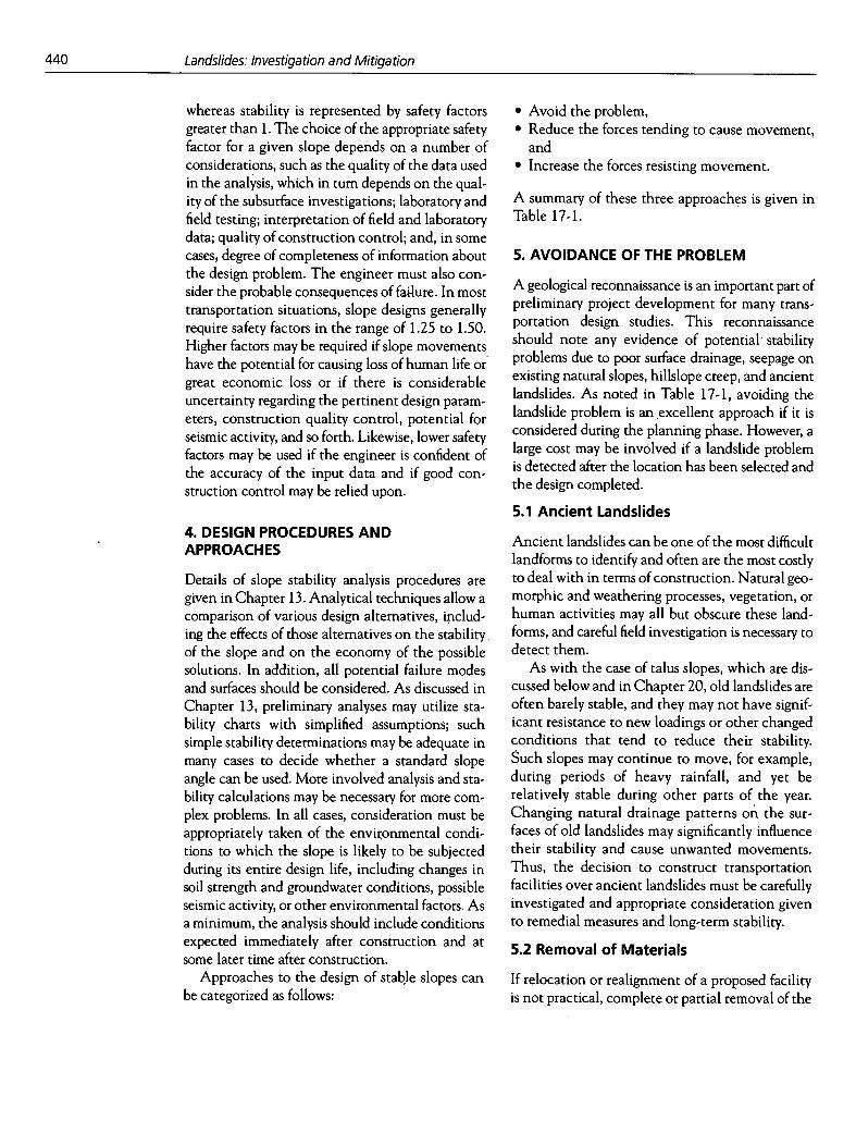
Increase internal Use biotechnical On soil slopes of modest Climate; may require irrigation Design is by trial and error strength stabilization heights in dry seasons; longevity of plus local experience (continued) selected plants
Treat chemically Where sliding surface May be reversible; long-term Laboratory study of soil- is well defined and soil effectiveness has not been chemical treatment must reacts positively to evaluated; environmental precede field installations; treatment stability unknown must consider environ-
mental effects Use electroosmosis To relieve excess pore Requires constant direct Used when nothing else
pressures and increase current power supply and works; emergency shear strength at a desir- maintenance stabilization of landslides able construction rate
Treat thermally To reduce sensitivity of Requires expensive and Methods are experimental clay soils to action of carefully designed system and costly water to artificially dry or
freeze subsoils
unstable materials should be considered. Figure 174 shows an example of one such study. Stability analyses indicated that removal of Volume B was more effective than removal of Volume A. Eco-nomics, as well as the potential increase in slope stability, will decide the final course of action.
Removal of potentially unstable materials can range from simple stripping of near-surface materi-als a few meters thick, as shown in Figure 17-2, to more complicated and costly operations such as those encountered in a sidehill cut along the Willamette River in West Linn, Oregon, where a section of 1-205 required extensive excavation to depths as great as 70 m (Gedney and Weber 1978).
5.3 Bridging
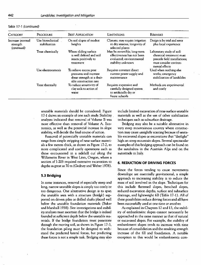
In some instances, removal of especially steep and long, narrow unstable slopes is simply too costly or too dangerous. One alternative design is to span the unstable area with a structure (bridg) sUp-ported on driven piles or drilled shafts placed well below the unstable foundation materials (Baker and Marshall 1958). Site investigations and stabil-ity analyses must ascertain that the bridge is indeed founded at sufficient depth below the unstable ma-terials. If the bridge foundation must penetrate through the moving soil, as shown in Figure 17-3, the foundation piling must be designed to with-stand the predicted lateral forces, but predicting these forces is not a simple task. Bridging may also
include limited excavation of near-surface unstable materials as well as the use of other stabilization techniques such as subsurface drainage.
Bridging may also be a suitable alternative in very steep mountainous country where construc-tion may cause unsightly scarring because of unsta-ble excavated slopes or excavations that "daylight" high on steep mountain slopes. Several spectacular examples of this bridging approach can be found on the autobahns in the Austrian Alps and on the autostrade in Italy.
6. REDUCTION OF DRIVING FORCES
Since the forces tending to cause movements downslope are essentially gravitational, a simple approach to increasing stability is to reduce the mass of soil involved in the slope. Techniques for this include flattened slopes, benched slopes, reduced excavation depths, surface and subsurface drainage, and lightweight fill (Table 17-1). All of these possibilities reduce driving forces and all have been successfully used at one time or another.
As explained in Chapters 12 and 13, the stabil-ity of embankment slopes cannot necessarily be approached in the same manner as that of natural or excavated slopes. For example, the stability of embankment slopes tends to increase with time because of consolidation and the resulting strength increase of the fill and foundation. A notable exception to this would be embankments corn-

Stabilization of Soil Slopes
443
FACTO RS OF SAFETY EXISTING SLOPE(ASSUMED)=1.00 VOLUME A REMOVED'=101 VOLUME B REMOVED =1.30
VOLUME A= VOLUME B
830 WEST 1600.
0
o..
1550
B 2
/ I- w // MESA VERDE
SANDSTONE 1500
o A LU
/ /
O / OLD TUNNEL ,' LNEW TUNNEL
1450
FILL
MANCOS SHALE DARKGRAY.HARD 026 40 60m
10 0 66 132 198ft 1400
FIGURE 17-1 Stabilization of Cameo slide above railroad in Colorado River Valley, Colorado, by partial removal of materials (Peck and Ireland 1953; Baker and Marshall 1958).
posed of degradable shalest and other soft rocks, which may deteriorate with time and result in set-tlement or even failure (see Chapter 21). In natural or excavated slopes, however, the long-term stabil-ity may be significantly less than that available at the end of construction. Design conditions that are appropriate for these cases are discussed in Chap-ters 12 and 13.
Talus slopes often have marginal stability (Ritchie 1963) and deserve special consideration (see Chapter 20). Runoff from normal rainfall or snowmek may cause sufficient increase in seepage pressures to initiate movement. Recognition of talus slopes is important in preliminary location designs because of the potential for dangerous movements. Such slopes may also be disturbed by
PROPOSED ROADWAY EMBANKMENT -\ FILL TO PROVIDE DRAINAGE
OR I G INAL GROUND LINE
UNSTABLESTRIPPE
t ..
FILTER MATERIAL FIRM MATERIAL
.0 5 lOm
0 16.5 33ft
OUTLET AT LOW POINT PROVIDED
FIGURE 17-2 Stripping of unstable surface material to reduce landslide potential for sidehill embankment (Root 1958).
444 Landslides: Investigation and Mitigation
FIGURE 17-3 Landslide avoidance by bridging near Santa Cruz, California (Root 1958).
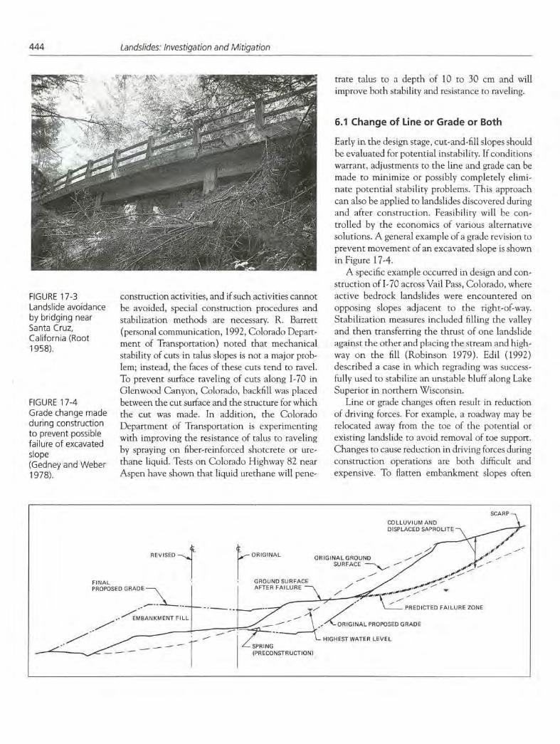
FIGURE 17-4 Grade change made during construction to prevent possible failure of excavated slope (Gedney and Weber 1978).
construction activities, and if such activities cannot be avoided, special construction procedures and stabilization methods are necessary. R. Barrett (personal communication, 1992, Colorado Depart.. ment of Transportation) noted that mechanical stability of cuts in talus slopes is not a major prob-lem; instead, the faces of these cuts tend to ravel. To prevent surface raveling of cuts along 1-70 in Glenwood Canyon, Colorado, backfill was placed between the cut surface and the structure for which the cut was made. In addition, the Colorado Department of Transportation is experimenting with improving the resistance of talus to raveling by spraying on fiber-reinforced shotcrete or ure-thane liquid. Tests on Colorado Highway 82 near Aspen have shown that liquid urethane will pene-
trate talus to a depth of 10 to 30 cm and will improve both stability and resistance to raveling.
6.1 Change of Line or Grade or Both
Early in the design stage, cut-and-fill slopes should be evaluated for potential instability. If conditions warrant, adjustments to the line and grade can be made to minimize or possibly completely elimi-nate potential stability problems. This approach can also be applied to landslides discovered during and after construction. Feasibility will be con-trolled by the economics of various alternative solutions. A general example of a grade revision to prevent movement of an excavated slope is shown in Figure 17-4.
A specific example occurred in design and con-struction of 1-70 across Vail Pass, Colorado, where active bedrock landslides were encountered on opposing slopes adjacent to the right-of-way. Stabilization measures included filling the valley and then transferring the thrust of one landslide against the other and placing the stream and high-way on the fill (Robinson 1979). Edit (1992) described a case in which regrading was success-fully used to stabilize an unstable bluff along Lake Superior in northern Wisconsin.
Line or grade changes often result in reduction of driving forces. For example, a roadway may be relocated away from the toe of the potential or existing landslide to avoid removal of toe support. Changes to cause redi.ction in driving forces during construction operations are both difficult and expensive. To flatten embankment slopes often
.?kL..
TTc;k1 - -
/
.- - -
-.
---
ScARF COLLUVIUM AND DISPLACED SAPROLITE
REVISED
FINAL
ORIGINAL ORIGINAL GROUND _ N
GROUND SURFACE
SURFACE -
AFTER FAILURE - ,.....
PREDICTED FAILURE ZONE
z"o."NALPROPOD GRADE
~q__
E
HIGHEST WATER LEVEL 7'P.ING

Stabilization of Soil Slopes
445
requires additional right-of-way and can involve alignment shifts that affect the design of facilities on either side of the problem area. Thus, changes in line and grade after construction may be so costly as to prevent their use. These comments emphasize the fact that the cost-effectiveness of geotechnical investigations is greatest when they are carried out during the preliminary design phases of the project.
Another technique for reducing the driving forces, especially for known unstable areas, is the partial removal or excavation of a sufficient quan-tity of slope material at the top of the landslide to ensure stability of the potential sliding mass (Figure 17-1). If an infinite slope condition exists or certain types of flow or debris slides are in-volved, this method may be ineffective. The quantity of material required to be removed is pre-dicted by trial and error using ordinary stability analysis (Chapters 12 and 13). As usual, economic considerations and potential use of the excavated materials may dictate whether unloading proce-dures are feasible for a particular project. In some instances—for example, when the project needs additional borrow materials—removal of the entire sliding mass may be feasible provided the material volumes are reasonable. The design of landslide removal should always consider the stability of the slope behind or above the area to be removed. Of course, this technique is most appro-priate during the design stage. These procedures usually involve slope flattening; in some cases, benching has been used to reduce the driving forces on a potential or existing landslide. Specific geometric constraints of the site will determine if benching is appropriate. As discussed in the fol-lowing section, benches also serve to help control surface runoff and provide work areas for place-ment of horizontal drains.
6.2 Drainage
Because of its high stabilization efficiency in rela-tion to design and construction costs, drainage of surface water and groundwater is the most widely used and generally the most successful slope stabi-lization method (Committee on Ground Failure Hazards 1985). Of all possible schemes to be con-sidered for the correction of existing or potential landslides, proper drainage is probably the single most important. Drainage will both reduce the weight of the mass tending to cause the landslide
and increase the strength of the materials in the slope. Increasing the strength of soil materials using drainage is discussed in Section 7.2.1.
6.2.1 Surface Drainage
Surface drainage measures require minimal engi-neering design and offer positive protection to slopes. Thus they are among the first approaches that should be considered in preventing potential stability problems.
Adequate surface drainage is necessary in new excavations as well as in maintenance of con-structed slopes where movement has already occurred. The design of cut slopes should always take into consideration the natural drainage pat-terns of the area and the effect that the constructed slope will have on these drainage patterns. Two conditions that should be evaluated are
Surface water flowing across the face of the slope, and Surface water seeping into or infiltrating into the head of the cut.
Both of these conditions cause erosion of the face and increase the tendency for localized failures on the slope face. Diversion ditches and interceptor drains are widely used as erosion control measures, especially in situations where large volumes of runoff are anticipated (Figure 17-5).
Good surface drainage is strongly recommended as part of the treatment of any landslide or poten-tial landslide (Cedergren 1989). Every effort should be made to ensure that surface waters are carried away from a slope. Such considerations become
FIGURE 17-5 Surface drainage of slope using diversion ditch and interceptor drain (Gedney and Weber 1978).

446
Landslides: Investigation and Mitigation
especially important when a failure has already occurred. Unless they are sealed, cracks and fissures behind the scarp face of a landslide can carry sur-face waters into the failure zone and reactivate the landslide. Consequently, reshaping the surface of the landslide mass can be very beneficial because unnoticed cracks and fissures may be sealed and water-collecting surface depressions eliminated.
There are a number of possibilities to treat the surface of the slope itself in order to promote rapid runoff and improve slope stability. Some of these measures are
Seeding, sodding, or mulching, and Using shotcrete, riprap, thin masonry, concrete paving, asphalt paving, and rock fills.
All of these techniques have been used successfully to protect slopes made of degradable shales or clay-stones and to prevent the infiltration of surface runoff. Techniques for controlling surface runoff are especially effective when used in conjunction with various subsurface drainage techniques.
The Geotechnical Control Office of Hong Kong (Geotechnical Control Office' 1984) has presented useful guidelines for the maintenance of surface drainage systems. These guidelix\es partic-ularly recommend the use of surface channels as opposed to pipes placed on the surface.
6.2.2 Subsurface Drainage
Because seepage forces act to increase the driving force on a landslide, control of subsurface water is of
major importance. lithe preliminary site investiga-tion reveals the presence of groundwater, if design studies predict potential downslope movements, and if positive subsurface drainage can reduce fail-ure potential, it is worth preparing a suitable design for cost comparison with other alternatives.
Subsurface drainage as a method of lowering the groundwater table within an unstable slope has traditionally consisted of one or more of the following procedures:
Drainage blankets and trenches; Drainage wells; Drainage galleries, adits, or tunnels; Subhorizontal (commonly called "horizontal") drains drilled either from the slope surface or from drainage wells or galleries; and Subvertical drains drilled upward from drainage galleries.
Most often these systems drain by means of grav-ity flow; however, pumps are occasionally used to remove water from low-level collector galleries or wells. Figure 17-6 is a schematic drawing showing some of these techniques.
The effectiveness and frequency of use of the var-ious types of drainage treatments vary according to the hydrogeologic and climatic conditions. It is gen-erally agreed, however, that groundwater constitutes the single most important cause of the majority of landslides. Thus, in many areas of the world the most generally used and successful methods for prevention and correction of landslides consist entirely or partially of groundwater control (Cedergren 1989).
U PS LOPE
PUMPED WELLS DRAINAGE DITCHES
VERTICAL GRAVITY
FIGURE 17-6 Schematic diagram of subhorizontal and vertical drains used to lower groundwater in natural slopes (Gedney and Weber 1978).
Stabilization of Soil Slopes
447
Subsurface drainage is equally important in cuts and embankments, and most types of subsurface drainage treatments are applicable to the preven-tion and correction of landslides in both situa-tions. When embankments are constructed on potentially unstable slopes, landslides may occur because the increase in shear stresses imposed by the embankment exceeds the shearing strength of the foundation soils. Instability may also result if the embankment interferes with the natural movement of groundwater. Therefore, in an in-vestigation of possible instability, two factors must be considered:
Weak zones in the foundation that may be over-stressed by the proposed embankment load, and Increases in pore-water pressure sufficient to cause a significant reduction in the shear strength of the soil.
Because there often is no surface indication of un-stable slope conditions, careful subsurface explor-ation is required if slope instability is to be predicted before construction.
Drainage is sometimes installed to intercept sub-surface water outside the limits of excavations, but it frequently is impossible to determine whether such interceptor trenches will effectively cut off all groundwater that might contribute to slope failure. Other methods that may be appropriate in sidehill embankment areas often are excessively expensive in excavation areas. Each case must be examined on an individual basis. The cost of drainage systems is generally lower when these measures are incor-porated into the preliminary design process. When they are included as remedial measures during or following construction or landslide movement, the drainage systems may be expensive.
In this section recent advances in subsurface drainage systems are discussed. In addition, a few less common means of drainage such as electro-osmosis, vacuum drains, siphons, and the use of geotextiles and geocomposites will be briefly mentioned.
6.2.2.1 Drainage Blankets and Trenches When an embankment is to be constructed over a surface layer of relitively shallow, weak soil un-derlain by stable rock or soil, usually the most eco-nomical treatment is to strip the unsuitable material, as shown in Figure 17-2. After stripping,
if seepage is evident or if there is a possibility that it may develop during wet periods, a blanket drain of pervious material (clean free-draining sands or gravels) should be placed before the embankment is constructed. If springs or concentrated flows are encountered, drainpipes may also be required.
When conditions are such that drainage blan-kets are uneconomical, for example, when the depth of unsuitable material to be stripped is large, trench drains may be appropriate. Trenches filled with free-draining material have been used effec-tively for shallow subsurface drainage for several decades. The trenches are excavated by backhoe-type excavators to depths of 5 to 6 m and by clamshells to greater depths; some type of tempo-rary support system may be required if the excava-tion is more than 5 to 6 In deep. Cancelli et at. (1987) provided a brief review of the theory for the design of trench drains. Sometimes single drainage trenches perpendicular to the center line of the facility are sufficient; in other situations, larger, more extensive networks of interconnected drains may be necessary. In addition to facilitating drainage, trench drains provide increased resis-tance to possible sliding because the compacted backfill of the trench section acts as a key into firmer material beneath the trench.
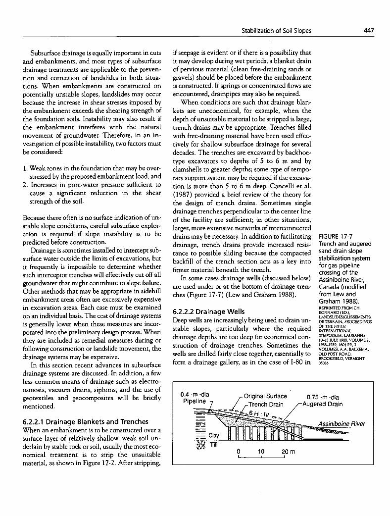
In some cases drainage wells (discussed below) are used under or at the bottom of drainage tren-ches (Figure 17-7) (Lew and Graham 1988).
6.2.2.2 Drainage Wells Deep wells are increasingly being used to drain un-stable slopes, particularly where the required drainage depths are too deep for economical con-struction of drainage trenches. Sometimes the wells are drilled fairly close together, essentially to form a drainage gallery, as in the case of 1-80 in
FIGURE 17-7 Trench and augered sand drain slope stabilization system for gas pipeline crossing of the Assiniboine River, Canada (modified from Lew and Graham 1988). REPRINTED FROM CH. BONNARD (ED.), LANDSLIDESIGLISSEMENTS DE TERRAIN, PROCEEDINGS OF THE FIFTH INTERNATIONAL SYMPOSIUM, LAUSANNE, 10-15 JULY 1988, VOLUME 2, 1988-1989, 1604 PP., 3 VOLUMES, A.A. BALKEMA, OLD POST ROAD, BROOKFIELD, VERMONT 05036
0.4 -m -dia Original Surface 0.75 -m -dia PiPelie TrenCh rai n _AU9ered Drain
- Clay 'llfl II River
Till 0 10 20m I I
448 Landslides: Investigation and Mitigation
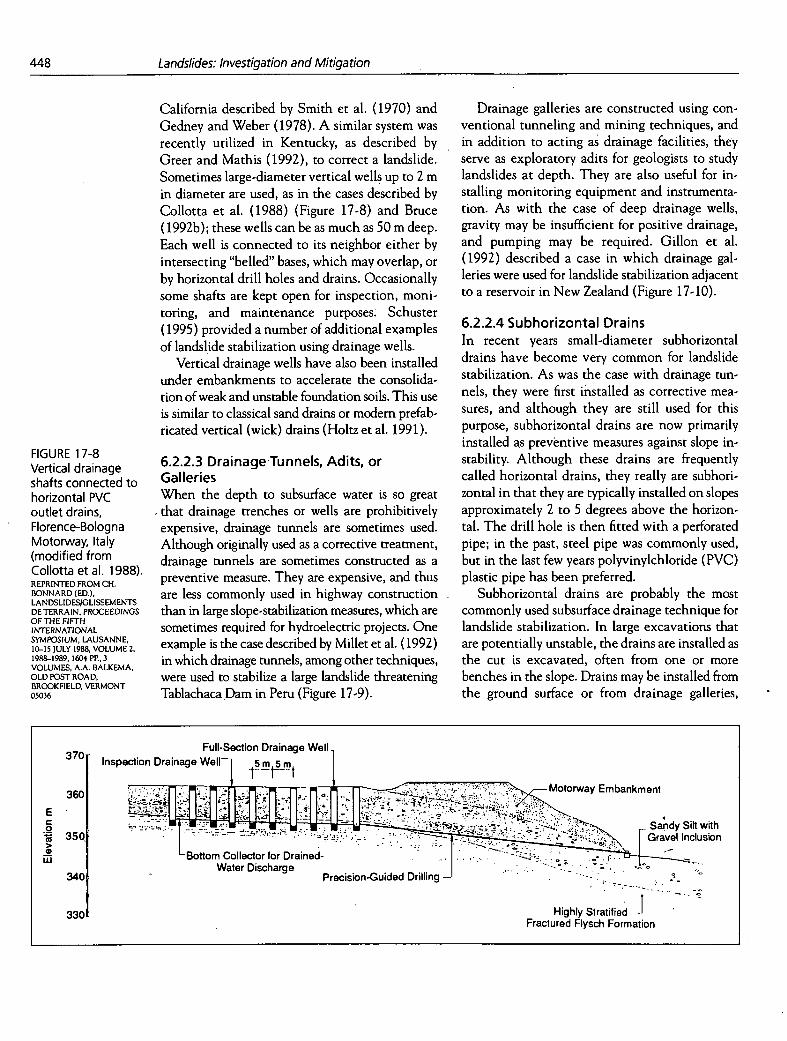
California described by Smith et at. (1970) and Gedney and Weber (1978). A similar system was recently utilized in Kentucky, as described by Greer and Mathis (1992), to correct a landslide. Sometimes large-diameter vertical wells up to 2 in in diameter are used, as in the cases described by Collotta et at. (1988) (Figure 17-8) and Bruce (1992b); these wells can be as much as 50 m deep. Each well is connected to its neighbor either by intersecting "belied" bases, which may overlap, or by horizontal drill holes and drains. Occasionally some shafts are kept open for inspection, moni-toring, and maintenance purposes. Schuster (1995) provided a number of additional examples of landslide stabilization using drainage wells.
Vertical drainage wells have also been installed under embankments to accelerate the consolida-tion of weak and unstable foundation soils. This use is similar to classical sand drains or modem prefab-ricated vertical (wick) drains (Holtz et al. 1991).
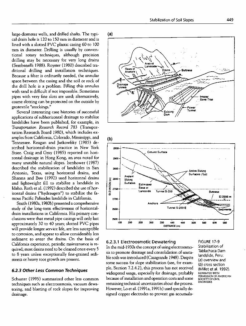
6.2.2.3 Drainage Tunnels, Adits, or Galleries When the depth to subsurface water is so great that drainage trenches or wells are prohibitively expensive, drainage tunnels are sometimes used. Although originally used as a corrective treatment, drainage tunnels are sometimes constructed as a preventive measure. They are expensive, and thus are less commonly used in highway construction than in large slope-stabilization measures, which are sometimes required for hydroelectric projects. One example is the case described by Millet et al. (1992) in which drainage tunnels, among other techniques, were used to stabilize a large landslide threatening Tablachaca Dam in Peru (Figure 17-9).
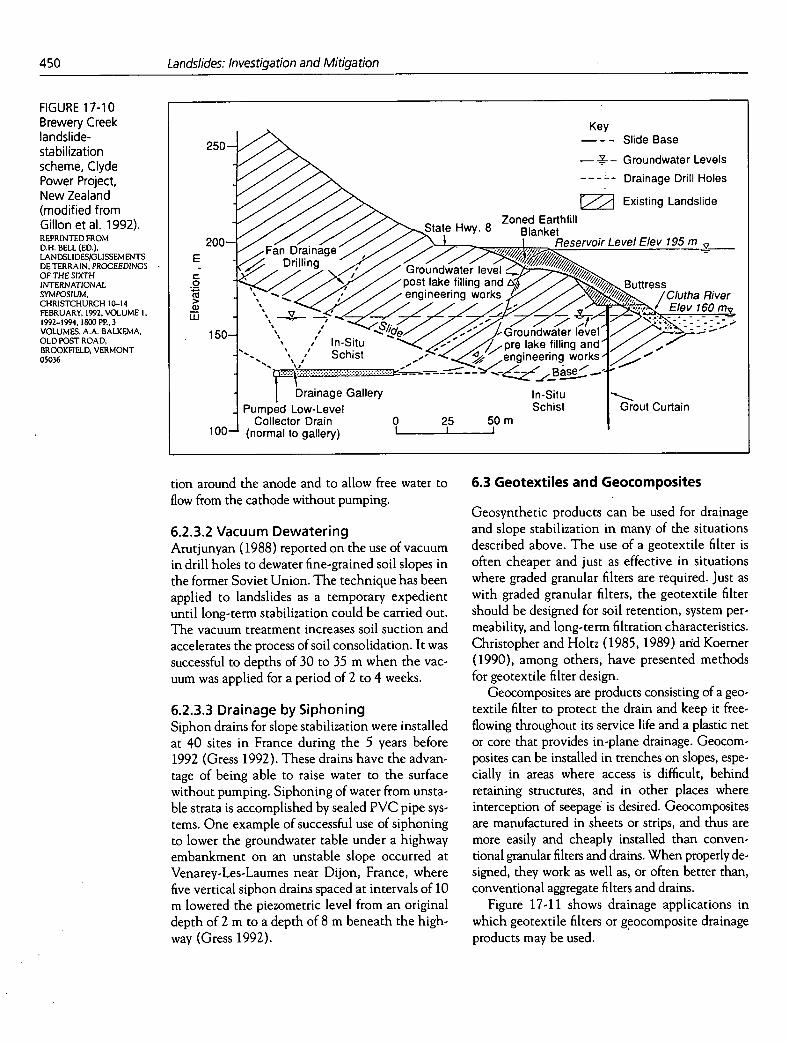
Drainage galleries are constructed using con-ventional tunneling and mining techniques, and in addition to acting as drainage facilities, they serve as exploratory adits for geologists to study landslides at depth. They are also useful for in-stalling monitoring equipment and instrumenta-tion. As with the case of deep drainage wells, gravity may be insufficient for positive drainage, and pumping may be required. Gillon et al. (1992) described a case in which drainage gal-leries were used for landslide stabilization adjacent to a reservoir in New Zealand (Figure 17-10).
6.2.2.4 Subhorizontal Drains In recent years small-diameter subhorizontal drains have become very common for landslide stabilization. As was the case with drainage tun-nels, they were first installed as corrective mea-sures, and although they are still used for this purpose, subhorizontal drains are now primarily installed as preventive measures against slope in-stability. Although these drains are frequently called horizontal drains, they really are subhori-zontal in that they are typically installed on slopes approximately 2 to 5 degrees above the horizon-tal. The drill hole is then fitted with a perforated pipe; in the past, steel pipe was commonly used, but in the last few years polyvinylchloride (PVC) plastic pipe has been preferred.
Subhorizontal drains are probably the most commonly used subsurface drainage technique for landslide stabilization. In large excavations that are potentially unstable, the drains are installed as the cut is excavated, often from one or more benches in the slope. Drains may be installed from the ground surface or from drainage galleries,
FIGURE 17-8 Vertical drainage shafts connected to horizontal PVC outlet drains, Florence-Bologna Motorway, Italy (modified from Collotta et al. 1988). REPRINTED FROM CH. BONNARD (ED.), LANDSLIDESIOLISSEMENTS DE TERRAIN, PROCEEDINGS OF THE FIFTH INTERNATIONAL SYMPOSIUM, LAUSANNE, 10-15 JULY 1988, VOLUME 2, 1988-1989, 1604 PP., 3 VOLUMES, A.A. BALKEMA, OLD POST ROAD, BROOKFIELD, VERMONT 05036
370 Inspection Drainage Full-Section Drainage Well1 Well 1rn1!_m1 . .
Motorway Embankment
::: Grav els ion CD Boflom Collector for Drained- Ui
Water
-
DrillIng
3301 Highly Stratified .1
Fractured Flysch Formation
Area of Lanoslide
Rows of Andors t
Drains _.- Buttress
\\ .... .. -
Drainage Tunnels
S -
Intal(&
I SarTrap
Power
Extsting Tunnel
-. Dam
29504- . I GrounoSuaca
2900 .
2950 .\ Acfive Sling
/ Anoent
. N. Surfas(Typ)
2800-i ng Surfaces Estimod
-::: '-'•
27504............................... Baseot /............. ....... ..... ................................ uj Lancslde Tunnel S.250 Buttreu Lu I / 2700-4 . .-
Anchors
2650 Tunnel 5-200 E .... .
150 200 250 300 350 400 450 4 S
500 550 600 650 DISTANCE (m)
Stabilization of Soil Slopes
449
large-diameter wells, and drilled shafts. The typi-cal drain hole is 120 to 150 mm in diameter and is lined with a slotted PVC plastic casing 60 to 100 mm in diameter. Drilling is usually by conven-tional rotary techniques, although precision drilling. may be necessary for very long drains (Sembenelli 1988). Royster (1980) described tra-ditional drilling and installation techniques. Because a filter is ordinarily needed, the annular space between the casing and the soil or rock of the drill hole is a problem. Filling this annulus with sand is difficult if not impossible. Sometimes pipes with very fine slots are used; alternatively, coarse slotting can be protected on the outside by geotextile "stockings."
Several interesting case histories of successful applications of subhorizontal drainage to stabilize landslides have been published, for example, in Transportation Research Record 783 (Transpor-tation Research Board 1980), which includes ex-amples from California, Colorado, Mississippi, and Tennessee. Reagan and Jutkowfsky (1985) de-scribed horizontal-drain practice in New York State. Craig and Gray (1985) reported on hori-zontal drainage in Hong Kong, an area noted for many unstable natural slopes. Isenhower (1987) described the stabilization of landslides in San Antonio, Texas, using horizontal drains, and Sharma and Buu (1992) used horizontal drains and lightweight fill to stabilize a landslide in Idaho. Roth et al. (1992) described the use of hor-izontal drains ("hydraugers") to stabilize the fa-mous Pacific Palisades landslide in California.
Smith (1980a, 1980b) presented a comprehensive study of the long-term effectiveness of horizontal-drain installations in California. His primary con-clusions were that metal pipe casings will only last approximately 30 to 40 years; slotted PVC pipes will provide longer service life, are less susceptible to corrosion, and appear to allow considerably less sediment to enter the drains. On the basis of California experience, periodic maintenance is re-quired; most drains need to be cleaned once every 5 to 8 years unless exceptionally fine-grained sedi-ments or heavy root growth are present.
6.2.3 Other Less Common Techniques
Schuster (1995) summarized other less common techniques such as electroosmosis, vacuum dewa-tering, and blasting of rock slopes for improving drainage.
6.2.3.1 Electroosmotic Dewatering In the mid-1930s the concept of using electroosmo-sis to promote drainage and consolidation of unsta-ble soils was introduced (Casagrande 1948). Despite some success for slope stabilization (see, for exam-ple, Section 7.2.4.2), this process has not received widespread usage, especially for drainage, probably because of installation and operation costs and some remaining technical uncertainties about the process. However, Lo et al. (1991a, 1991b) used specially de-signed copper electrodes to prevent gas accumula-
FIGURE 17-9 Stabilization of Tablachaca Dam landslide, Peru:
overview and cross section
(Millet et al. 1992). REPRINTED WITH PERMISSION OF AMERICAN SOCIETY OF CIVIL ENGINEERS
450
Landslides: Investigation and Mitigation
Key
250 - - - Slide Base
---- Groundwater Levels Drainage Drill Holes
Existing Landslide Zoned Earthfill
State Hwy. 8 Blanket 200-
Fan Drainage . Reservoir Level EIev 195 m
, E - Drilling Groundwater level .2 ' post Buttress
engineering works ii "///// /Clutha River
150
Base
Drainage Gallery In-Situ Pumped Low-Level Schist Grout Curtain
Collector Drain 0 25 50 m 100 (normal to gallery) I I
FIGURE 17-10 Brewery Creek landslide-stabilization scheme, Clyde Power Project, New Zealand (modified from Gillon et al. 1992). REPRINTED FROM D.H. BELL (ED.). LANDSLIDES/OLISSEMENTS DE TERRAIN, PROCEEDINGS OF THE SIXTH INTERNATIONAL SYMPOSIUM, CHRISTCHURCH 10-14 FEBRUARY, 1992, VOLUME I, 1992-1994, I800PP.,3 VOLUMES, A.A. BALKEMA, OLD POST ROAD, BROOKFIELD, VERMONT 05036
tion around the anode and to allow free water to flow from the cathode without pumping.
6.2.3.2 Vacuum Dewatering Arutjunyan (1988) reported on the use of vacuum in drill holes to dewater fine-grained soil slopes in the former Soviet Union. The technique has been applied to landslides as a temporary expedient until long-term stabilization could be carried out. The vacuum treatment increases soil suction and accelerates the process of soil consolidation. It was successful to depths of 30 to 35 m when the vac-uum was applied for a period of 2 to 4 weeks.
6.2.3.3 Drainage by Siphoning Siphon drains for slope stabilization were installed at 40 sites in France during the 5 years before 1992 (Gress 1992). These drains have the advan-tage of being able to raise water to the surface without pumping. Siphoning of water from unsta-ble strata is accomplished by sealed PVC pipe sys-tems. One example of successful use of siphoning to lower the groundwater table under a highway embankment on an unstable slope occurred at Venarey-Les-Laumes near Dijon, France, where five vertical siphon drains spaced at intervals of 10 m lowered the piezometric level from an original depth of 2 m to a depth of 8 m beneath the high-way (Gress 1992).
6.3 Geotextiles and Geocomposites
Geosynthetic products can be used for drainage and slope stabilization in many of the situations described above. The use of a geotextile filter is often cheaper and just as effective in situations where graded granular filters are required. Just as with graded granular filters, the geotextile filter should be designed for soil retention, system per-meability, and long-term filtration characteristics. Christopher and Holtz (1985, 1989) and Koemer (1990), among others, have presented methods for geotextile filter design.
Geocomposites are products consisting of a geo-textile filter to protect the drain and keep it free-flowing throughout its service life and a plastic net or core that provides in-plane drainage. Geocom-posites can be installed in trenches on slopes, espe-cially in areas where access is difficult, behind retaining structures, and in other places where interception of seepage is desired. Geocomposites are manufactured in sheets or strips, and thus are more easily and cheaply installed than conven-tional granular filters and drains. When properly de-signed, they work as well as, or often better than, conventional aggregate filters and drains.
Figure 17-11 shows drainage applications in which geotextile filters or geocomposite drainage products may be used.

Stabilization of Soil Slopes
451
(a)
toc . lOOoO
42QQQ..
(b)
panded polystyrene, shredded and chipped tires, FIGURE 17-11 and oyster shells and clamshells. The advantages Drainage
and disadvantages of the use of many of these ma- applications using
terials were described by Hokz (1989). geotextiles or geocomposites:
Several examples of the use of lightweight fill trench drain, materials to stabilize landslides have been given in interceptor drain, the literature. Nelson and Allen (1974) reported and (c) drainage on a successful landslide correction using chipped behind structure
bark and sawdust to produce a sidehill embank- (modified from
ment weighing about 5 kN/m3. They used a 0.3-m Christopher and
gravel base under the pavement section; in addi- Holtz 1989).
tion, an asphalt seal was placed on the exposed slope to retard deterioration and pollution. Since then there have been many other similar projects in the Pacific Northwest. Yeh and Gilmore (1992) reported the use of expanded polystyrene (EPS) to correct a large landslide in southern Colorado. The landslide was successfully stabilized by using a counterweight berm at the toe and replacing the landslide material in the embankment with EPS with a unit weight of about 0.2 kN/m3. Sharma and Buu (1992) used pumice weighing about 12 kN/m3 in the correction of a landslide on 1-15 in Idaho. Shredded waste tires weighing about 6.4 kN/m3 were used as lightweight fill in the correc- tion of a landslide under a highway embankment on Highway 42 in Oregon (Read et al. 1991). Humphrey and Manion (1992) conducted tests on tire chips to determine their basic properties.
6.4 Reduction of Weight
Especially in embankment construction, the use of lightweight backfill materials can be very effective in reducing the gravitational driving forces tend-ing to cause instability. Lightweight materials that have been successfully used in highway embank-ments include chipped bark, sawdust, dried peat, fly ash, slag, cinders, cellular concrete, expanded clay or shale, lightweight geologic materials, ex-
7. INCREASE IN RESISTING FORCES
The third general method for stabilizing earth slopes is to increase the resisting forces on a po-tential or existing landslide. Although techniques vary widely, they generally function by either
Applying a resisting force at the toe of a land-slide, or Increasing the internal strength of the soils in the failure zone so that the slope remains stable without external assistance (Table 17-1).
Both approaches should be considered during pre-liminary design investigations to ensure the best technical and economical solution. The tech-niques described in this section to correct land-slides are appropriate for those that occur both during and after construction.
A number of procedures have been developed that increase the resisting forces at the toe of a p0-
452
Landslides: Investigation and Mitigation- -
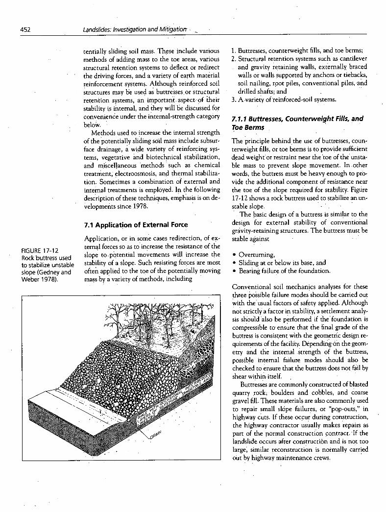
FIGURE 17-12 Rock 'buttress used to stabilize unstable slope (Gedney and Weber 1978).
tentially sliding soil mass. These include various methods of adding mass to the toe areas, various structural retention systems to deflect or redirect the driving forces, and a variety of earth matérial reinforcement systems. Although reinforced soil structures may be used as buttresses or structural retention systems, an important- aspect- - of iheir stability is internal, and they will be discussed for convenience under the internal-strength category below.
Methods used to increase the internal strength of the potentially sliding soil mass include subsur-face drainage, a wide variety of reinforcing sys-tems, vegetative and biotechnical stabilization, and miscellaneous methods such as chemical treatment; electroosmosis, and thermal stabiliza-tion. Sometimes a combination of external and internal treatments is employed. In the following description of these techniques, emphasis is on de- velopmetits since 1978. -
7.1 Application of External Force
Application, or in some cases redirection, of ex-ternal forces so as to increase the resistance of the slope to - pbtential movements will increase the stability of a slope. Such resisting forces are most often applied to the toe of the potentially moving mass-by a variety of methods, including -
Buttresses, counterweight fills, and toe berms; Structural retention systems such as cantilever and gravity retaining walls, externally, braced walls or walls supported by anchors or tiebacks, soil nailing, root piles, conventional piles, and drilled shafts; and - A -variety of'reinforced-soil systems.
7.1.1 Buttresses, Counterweight Fills, and Toe Berms
The principle behind,the use of buttresses, coun-terweight fills, or toe berms is to provide sufficient dead weight'or restraint near the 'toe of the unsta-ble mass to prevent slope movement. In-other words, the buttress must be heavy enough to prO-vide the additional component of resistance near the toe of the slope required for stability. Figure 17-12 shows a rock buttress used to stabilize an un- stable slope. .
- The basic design of a buttress is similar to the design for external stability, of conventional gravity-retaining structures. The buttress must be stable against
Overturning, Sliding at or below its base, and Bearing failure of the foundation.
Conventional soil mechanics analyses for these three possible failure modes should be carried out with the 'usual factors of safety applied. Although not strictly a factor in stability, a settlement analy-sis should 'also be performed if the'foundation is compressible to. ensure that the 'final grade of the buttress is consistent with the geometric design re-quirements of the facility. Depending-on the geom-etry and the internal strength of the buttress, possible internal failure modes should also be checked to ensure that the buttress does not fail by shear within-itself. -
Buttresses are commonly constructed of blasted quarry rock, boulders and cobbles, and coarse gravel fill. These materials are also commonly used to repair small slope failures, or "pop-outs," in highway cuts. If these occur duriiig construction, the highway contractor usually makes repairs as part of the normal construction contract. If the landslide occurs after construction and is not too large, similar reconstruction is normally carried out by highway -maintenance crews.
metallic, polymeric • soil nailing and organic • reticulated reinforcing strips micro piles and grids • soil doweling
anchored earth
masonry concrete cantilever countertort gabion crib bin ceIlul coffe
HYBRID SYSTEMS - SPECIAL MATERIALS tailed gabions • polymer-impregnated soil tailed masonry • low-density fills
- low-density concrete - expanded polystyrene
timber precast concrete sheet piles soldier piles cast in-situ - slurry walls - secant pile - tangent pile bored-in-place
(piles not contiguous)
soil-cement
Braced Tied-Back
cross-lot • augered rakers • belied
pressure-injected
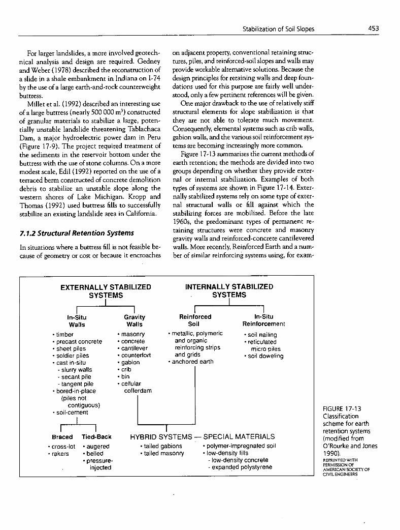
FIGURE 17-13 Classification scheme for earth retention systems (modified from O'Rourke and Jones 1990). REPRINTED WITH PERMISSION OF AMERICAN SOCIETY OF CIVIL ENGINEERS
Stabilization of Soil Slopes
453
For larger landslides, a more involved geotech-nical analysis and design are required. Gedney and Weber (1978) described the reconstruction of a slide in a shale embankment in Indiana on 1-74 by the use of a large earth-and-rock counterweight buttress.
Millet et al. (1992) described an interesting use of a large buttress (nearly 500 000 m3) constructed of granular materials to stabilize a large, poten-tially unstable landslide threatening Tablachaca Dam, a major hydroelectric power dam in Peru (Figure 17-9). The project required treatment of the sediments in the reservoir bottom under the buttress with the use of stone columns. On a more modest scale, Edil (1992) reported on the use of a terraced berm constructed of concrete demolition debris to stabilize an unstable slope along the western shores of Lake Michigan. Kropp and Thomas (1992) used buttress fills to successfully stabilize an existing landslide area in California.
7.1.2 Structural Retention Systems
In situations where a buttress fill is not feasible be-cause of geometry or cost or because it encroaches
on adjacent property, conventional retaining struc-tures, piles, and reinforced-soil slopes and walls may provide workable alternative solutions. Because the design principles for retaining walls and deep foun-dations used for this purpose are fairly well under-stood, only a few pertinent references will be gh'en.
One major drawback to the use of relatively stiff structural elements for slope stabilization is that they are not able to tolerate much movement. Consequently, elemental systems such as crib walls, gabion walls, and the various soil reinforcement sys-tems are becoming increasingly more common.
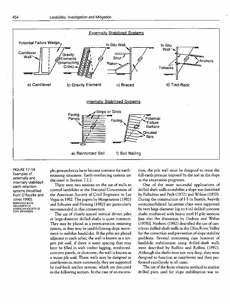
Figure 17-13 summarizes the current methods of earth retention; the methods are divided into two groups depending on whether they provide exter-nal or internal stabilization. Examples of both types of systems are shown in Figure 17-14. Exter-nally stabilized systems rely on some type of exter-nal structural walls or fill against which the stabilizing forces are mobilized. Before the late 1960s, the predominant types of permanent re-taining structures were concrete and masonry gravity walls and reinforced-concrete cantilevered walls. More recently, Reinforced Earth and a num-ber of similar reinforcing systems using, for exam-
EXTERNALLY STABILIZED
INTERNALLY STABILIZED SYSTEMS
SYSTEMS
In-Situ Gravity
Reinforced In-Situ Walls Walls
Soil Reinforcement
454 Landslides: Investigation and Mitigation
Externally Stabilized Systems
Potential Failure Wedge In-Situ Wall tn-Situ Wall /
Cantilever
_____ ____ / Gravity Wall 4lElements
J
/ nchors / (Interlocking
Tiebacks /
a) Cantilever b) Gravity Element c) Braced d) Tied-Back
Internally Stabilized Systems
-Strips or Grids Facing y
els / a ll,c
PanE
/ Facing otential Failure Surface
Grouted Bars I
e) Reinforced Soil f) Soil Nailing
FIGURE 17-14 pIe, geosynthetics have become common for earth- Examples of retaining structures. Earth-reinforcing systems are externally and internally stabilized
discussed in Section 7.2.2.
earth retention There were two sessions on the use of walls to
systems (modified control landslides at the National Convention of
from O'Rourke and the American Society of Civil Engineers in Las Jones 1990). Vegas in 1982. The papers by Morgenstem (1982) REPRINTEDWrni and Schuster and Fleming (1982) are particularly AMERICAN SOCIETY OF recommended in this connection.
The use of closely spaced vertical driven piles or large-diameter drilled shafts is quite common. They may be placed as a preexcavation retaining system, or they may be used following slope move- ment to stabilize landslides. If the piles are placed adjacent to each other, the wall is known as a tan- gent pile wall; if there is some spacing that may later be filled in with timber lagging, reinforced- concrete panels, or shotcrete, the wall is known as a secant pile wall. These walls may be designed as cantilevers or, more commonly, they are supported by tied-back anchor systems, which are discussed in the following section. In the case of an excava-
tion, the pile wall must be designed to resist the full earth pressure imposed by the soil in the slope as the excavation progresses.
One of the more successful applications of drilled shaft walls to stabilize a slope was described by Palladino and Peck (1972) and Wilson (1970). During the construction of 1-5 in Seattle, heavily overconsolidated lacustrine clays were supported by very large diameter (up to 4 m) drilled concrete shafts reinforced with heavy steel H-pile sections [see also the discussion by Gedney and Weber (1978)]. Nethero (1982) described the use of can-tilever drilled-shaft walls in the Ohio River Valley for the correction and prevention of slope stability problems. Several interesting case histories of landslide stabilization using drilled-shaft walls were described by Rollins and Rollins (1992). Although the shafts were not very deep, they were designed to function as cantilevers and they per-formed excellently in all cases.
The use of the finite-element method to analyze drilled piers used for slope stabilization was re-

Stabilization of Soil Slopes
455
ported by Oakland and Chameau (1984), and Reese et al. (1992) presented a method for the analysis of drilled shafts used for increasing the sta-bility of slopes. A design procedure for walls em-bedded in failed slopes vas proposed by Isenhower et al. (1989), who reported that such walls supported by 0.5- and 0.6-m-diameter shafts are much more economical than conventional earth-retaining structures used for landslide correction.
According to Gedney and Weber (1978), at-tempts to stabilize landslides using driven steel or timber piles have seldom been successful. Depending on the geologic conditions at the site, piles may be difficult to drive to the desired depth, and in the case of steel H-piles, for example, it is difficult to drive them vertically or in tangent. In Scandinavia there has been some success in the use of both timber and steel piles to stabilize mov-ing slopes and embankments (Bjerrum 1972); at these sites the subsurface conditions were rela-tively soft glacial and postglacial marine clays.
7.1.3 Anchor Systems
One of the more effective measures for stabilizing landslides is the use of anchor systems fo increase the resisting forces by applying external restraint to a moving soil mass [Figure 17-13 and Figure 17-14(d)]. These developments followed from the use of tiebacks to support walls for temporary ex-cavations for the construction of buildings and other structures.
According to Gould (1990), tieback anchors were developed as early as the 1930s from Euro-pean experience with permanent rock anchors in dam stabilization. In the early 1960s their use in Milwaukee and New York for building excavations clearly indicated the advantages of an uncluttered working space achieved by eliminating external supports [compare Figure 17-14(c) and 17-14(d)], and this successful application led to rapid devel-opments in the use of high-capacity prestressed anchors to support deep excavations. Tiebacks were also used to stabilize landslides in Europe in the mid-1960s, and, soon after, the technology was being employed in North America for similar purposes. An excellent description of the use of tiebacks for landslide stabilization was provided by Weatherby and Nicholson (1982). They described the design, installation, and corrosion protection that are necessary for permanent ground anchors
in landslide stabilization. A spectacular use of ground anchors was described by Millet et al. (1992) in which high-capacity rock anchors were used together with a granular buttress to stabilize a large landslide at Tablachaca Dam in Peru (Figure 17-9). Interesting case histories describing the use of tiebacks together with drilled shafts and driven H-pile walls were presented by Hovland and Willoughby (1982) and Tysinger (1982).
Other related systems such as soil nailing [Figure 17-14(f)] and micropiles increase the in-ternal strength of the sliding mass rather than ap-plying external force. Thus, these systems are discussed in the following section.
7.2 Increase in Internal Strength
Techniques that are used to increase the internal strength of the potentially unstable soil mass for both backfills and in situ stabilization are discussed next. These include subsurface drainage, soil- reinforcing systems, vegetative and biotechnical stabilization techniques, and miscellaneous techniques such as chemical, electrical, and thermal stabilization.
7.2.1 Subsurface Drainage
As noted by Gedney and Weber (1978), one of the most effective treatments for landslides and other unstable slopes is to increase the shear strength of the soil by means of subsurface drainage. Drainage reduces the excess pore pres-sures in the soil mass, which increases the effective stress on the potential failure surface. Subsurface drainage techniques are discussed in detail in Section 6.2.2.
7.2.2 Soil Reinforcement
Soil reinforcement is the inclusion of tensile resis-tant elements in a soil mass to improve its overall shearing resistance. One of the most exciting de-velopments in geotechnical engineering practice in the past 25 years, soil reinforcement is a tech-nically attractive and very cost-effective tech-nique for increasing the stability of natural and embankment soil slopes and for reducing the earth pressures against retaining walls and abutments.
As noted in Figure 17-13, internally stabilized soil systems can be conveniently divided into re-inforced soil [Figure 17-14(e)] and in situ rein-
Landslides: Investigation and Mitigation
forcement. In situ reinforcement systems include soil nailing [Figure 17-14(J)], micropiles, pin piles, and root piles. Reinforced soil is applicable to sit-uations in which the reinforcement and backfill are placed as the slope or wall is constructed. Common reinforcing elements include steel strips (Reinforced Earth), welded wire sheets, bar mats and meshes, geotextiles, geogrids, and fibers.
Excellent general discussions of internally sta-bilized soil reinforcement systems include those by Lee et al. (1973), Jones (1985), Mitchell and Villet (1987), Christopher et al. (1990), Mitchell and Christopher (1990), and O'Rourke and Jones (1990). This discussion will deal with recent advances in the use of internally stabilized soil re-inforcement systems.
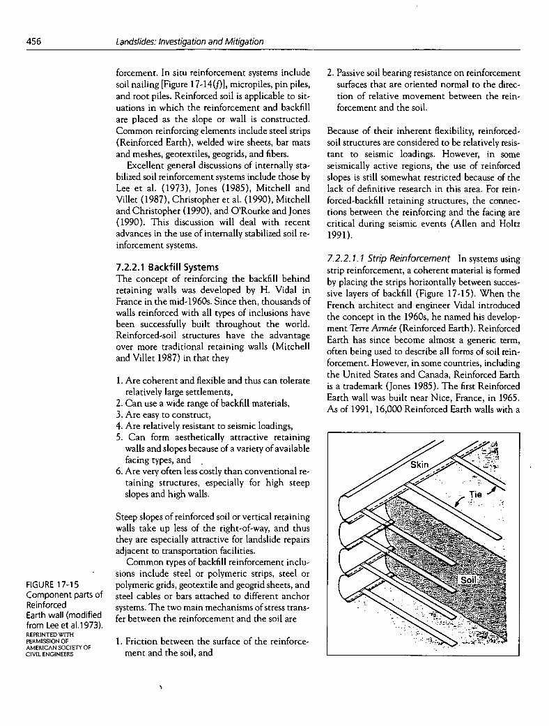
2. Passive soil bearing resistance on reinforcement surfaces that are oriented normal to the direc-tion of relative movement between the rein-forcement and the soil.
Because of their inherent flexibility, reinforced-soil structures are considered to be relatively resis-tant to seismic loadings. However, in some seismically active regions, the use of reinforced slopes is still somewhat restricted because of the lack of definitive research in this area. For rein-forced-backfill retaining structures, the connec-tions between the reinforcing and the facing are critical during seismic events (Allen and Holtz 1991).
FIGURE 17-15 Component parts of Reinforced Earth wall (modified from Lee et al.1973). REPRINTED WITH PERMISSION OF AMERICAN SOCIETY OF CIVIL ENGINEERS
7.2.2.1 Backfill Systems The concept of reinforcing the backfill behind retaining walls was developed by H. Vidal in France in the mid-1960s. Since then, thousands of walls reinforced with all types of inclusions have been successfully built throughout the world. Reinforced-soil structures have the advantage over more traditional retaining walls (Mitchell and Villet 1987) in that they
Are coherent and flexible and thus can tolerate relatively large settlements, Can use a wide range of backfill materials, Are easy to construct, Are relatively resistant to seismic loadings, Can form aesthetically attractive retaining
walls and slopes because of a variety of available facing types, and Are very often less costly than conventional re-taining structures, especially for high steep slopes and high walls.
Steep slopes of reinforced soil or vertical retaining walls take up less of the right-of-way, and thus they are especially attractive for landslide repairs adjacent to transportation facilities.
Common types of backfill reinforcement inclu-sions include steel or polymeric strips, steel or polymeric grids, geotextile and geogrid sheets, and steel cables or bars attached to different anchor systems. The two main mechanisms of stress trans-fer between the reinforcement and the soil are
1. Friction between the surface of the reinforce-ment and the soil, and
7.2.2. 1. 1 Strip Reinforcement In systems using strip reinforcement, a coherent material is formed by placing the strips horizontally between succes-sive layers of backfill (Figure 17-15). When the French architect and engineer Vidal introduced the concept in the 1960s, he named his develop-ment Terre Armée (Reinforced Earth). Reinforced Earth has since become almost a generic term, often being used to describe all forms of soil rein-forcement. However, in some countries, including the United States and Canada, Reinforced Earth is a trademark (Jones 1985). The first Reinforced Earth wall was built near Nice, France, in 1965. As of 1991, 16,000 Reinforced Earth walls with a

a I I I I
e) Sloping geotextile facing
Stabilization of Soil Slopes
457
total face area of 9 600 000 m2 had been con-structed worldwide (D. McKittrick, personal com-munication, 1991, Reinforced Earth Company, McLean, Virginia). Schlosser (1990) observed that about one-third of the Reinforced Earth wall area in the world has been built in Europe and about one-third in North America.
After the introduction of Reinforced Earth, knowledge of soil reinforcement increased rapidly, primarily because of the research sponsored by government agencies, notably the Laboratoire Central des Ponts et Chaussées (LCPC) in France, the Federal Highway Administration in the United States, and the Department of Transport in the United Kingdom.
Early experiments with fiberglass-reinforced polymers (Schlosser 1990), stainless steel, and alu-minum strips for Reinforced Earth walls were not successful, so all Reinforced Earth walls currently are constructed using galvanized steel strips. However, corrosion rates of metals in soils are very difficult to predict, and even galvanized steel is subject to corrosion; thus free-draining sand-and-gravel backfills are specified to reduce corrosion potential. Epoxy-coated steel strips have been de-veloped and may offer higher resistance to corro-sion. Elias (1990) discussed the corrosion of epoxy strips as well as traditional steel-strip reinforcing.
In 1973 nonmetallic reinforcing strips were in-troduced in construction of a highway retaining wall in Yorkshire, England (Holtz 1978; Jones 1978). The reinforcing strips were made of con-tinuous glass fibers embedded lengthwise in a pro-tective coating of epoxy resin. The Paraweb strip, in which the fibers are made of high-tenacity poly-ester or polyamarid, is another example of a geosynthetic strip reinforcement.
7.2.2. 1.2 Sheet Rein forcément In sheet rein-forcement, geotextiles are placed horizontally be-tween layers of embankment soils to form a composite reinforced-soil system. Figure 17-16 shows a number of possible uses of geotextiles in reinforced walls and slopes. The mechanism of stress transfer in sheet reinforcement is predomi-nantly friction (Mitchell and Villet 1987; Chris-topher and Holtz 1989; Christopher et al. 1990). A large variety of geotextiles with a wide range of mechanical properties is available; they include nonwoven needle-punched or heat-bonded poly-ester and polypropylene and woven polypropylene
40,
a) Vertical geotextile facing
Vertical precast concrete element facing
1.1
Vertical cast in-place concrete/masonry facing
and polyester geotextiles (Christopher and Holtz 1989; Koerner 1990). Granular soils ranging from silty sands to gravels commonly are used as back-fill, and the most common facings are formed by wrapping the geotextile around the exposed soil [Figure 17-16(a) and 17-16(e)]. Because geotex-tiles are subject to vandalism and deterioration from ultraviolet light, for long-term protection the
I
I
FIGURE 17-16 Possible reinforced walls and slopes using geosynthetic reinforcement (modified from Mitchell and Villet 1987).
f) Sloping gunite or structural facing
g) Sloping soil and vegetation facing
d) Vertical masonry facing h) Geotextile gabion
458
Landslides: Investigation and Mitigation
FIGURE 17-17 Geosynthetic-reinforced wall on -90 in Seattle, Washington. COURTESY OFT. M. ALLEN, WASHINGTON STATE DEPARTMENT OF TRANSPORTATION
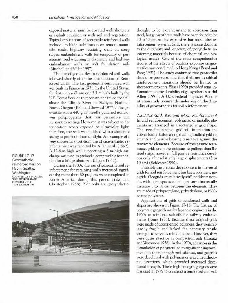
exposed material must be covered with shotcrete or asphalt emulsion or with soil and vegetation. Typical applications of geotext ile -reinforced walls include landslide stabilization on remote moun-tain roads, highway retaining walls on steep slopes, embankment walls for temporary or per-manent road widening or diversion, and highway embankment walls on soft foundation soils (Mitchell and Villet 1987).
The use of geotextiles in reinforced-soil walls followed shortly after the introduction of Rein-forced Earth. The first geotextile-reinforced wall was built in France in 1971. In the United States, the first such wall was one 3.3 rn high built by the U.S. Forest Service to reconstruct a failed road fill above the Illinois River in Siskiyou National Forest, Oregon (Bell and Steward 1977). The ge-otextile was a 440-g/rn2 needle-punched nonwo-yen polypropylene that was permeable and resistant to rotting. However, it was subject to de-terioration when exposed to ultraviolet light; therefore, the wall was finished with a shotcrete facing to protect it from sunlight. An example of a very successful short-term use of geosynthetic re-inforcement was reported by Allen et al. (1992). A 12.6-rn-high wall supporting a 6-rn-high sur-charge was used to preload a compressible founda-tion for a bridge abutment (Figure 17-17).
During the 1980s, the use of geotextile soil re-inforcement for retaining walls increased signifi-cantly; more than 80 projects were completed in North America during this period (Yako and Christopher 1988). Not only are geosynthetics
thought to be more resistant to corrosion than steel, but geosynthetic walls have been found to be 30 to 50 percent less expensive than most other re-inforcement systems. Still, there is some doubt as to the durability and longevity of geosynthetic re-inforcing materials because of chemical and bio-logical attack. One of the most comprehensive studies of the effects of outdoor exposure on geo-textiles was conducted in Hong Kong (Brand and Pang 1991). The study confirmed that geotextiles should be protected and that their use in critical reinforcement situations should be limited to short-term projects. Elias (1990) provided some in-formation on the durability of geosynthetics, as did Allen (1991). A U.S. Federal Highway Admin-istration study is currently under way on the dura-bility of geosynthetics for soil reinforcement.
7.2.2. 1.3 Grid, Bar, and Mesh Reinforcement In grid reinforcement, polymeric or metallic ele-ments are arranged in a rectangular grid shape. The two-dimensional grid-soil interaction in-volves both friction along the longitudinal grid el-ements and passive bearing resistance against the transverse elements. Because of this passive resis-tance, grids are more resistant to pullout than flat steel strips; however, full passive resistance devel-ops only after relatively large displacements (5 to 10 cm) (Schlosser 1990).
Probably the greatest development in the use of grids for soil reinforcement has been polymeric ge-ogrids. Geogrids are relatively stiff, netlike materi-als, with open spaces called apertures that usually measure 1 to 10 cm between the elements. They are made of polypropylene, polyethylene, or PVC-coated polyester.
Applications of grids to reinforced walls and slopes are shown in Figure 17-16. The first use of polymeric geogrids was by Japanese engineers in the 1960s to reinforce subsoils for railway embank-ments (Jones 1985). Because these original grids were made of nonoriented polymers, they were rel-auvely fragile and lacked the necessary tensile strength to sc'rvc i,, reinforceixieui. I luwever, they were quite effective as compaction aids (Iwasaki and Watanabe 1978). In the 1970s, advances in the lormulatioti of polymers led to significant improve-ments in rheir strength and stiffness, and geogrid were developed with polymers oriented in orthogo-nal directions, which provided increased direc-tional strength. These high-strength geogrids were lust used in 1979 to construct a reinforced-soil wall

.,-.. -.-. 4• _i..
Stabilization of Soil Slopes
459
at a railroad station in Yorkshire (O'Rourke and Jones 1990).
In 1981 geogrids were used to repair slope fail-ures in cuts on the Ml and M4 motorways in England (Murray and Irwin 1981; Murray 1982; Jones 1985). Considerable cost savings resulted because the landslide debris was reused together with the geogrid reinforcement (Figure 17-18). No new backfill material was required. In 1983 the first geogrid wall in the United States was built to stabilize a landslide near Newport on the Oregon coast (Szymoniak et al. 1984). This 9-rn-high ge-ogrid wall with a face slope of 80 degrees was se-lected over other alternatives because
It had the lowest estimated cost, and The open face of the grid wall allowed estab-lishment of vegetation that provided a natural appearance compatible with the surroundings of the adjacent state park.
At about the same time, Forsyth and Bieber (1984) reported on the construction of a geogrid-reinforced slope in California to repair a slope fail-ure. It was 9.5 in high and had a slope of 48 degrees. Figure 17- 19(a) shows the slope under construction, and Figure 17-19(b) shows the com-pleted structure. Since the construction of these early walls, more than 300 polymeric geogrid walls and slopes have been constructed in the United States (Mitchell and Christopher 1990). Figure 17-20 shows another, nearly completed landslide repair on a state highway in California.
Several bar-and-mesh reinforcement systems have been developed that rely on hoth frictional and passive resistance to pullout. In 1974 the first "bar mat" system of soil reinforcement was devel-oped by the California Department of Trans-portation (Caltrans) to construct a 6-rn-high wall along I-S near Dunsmuir, California; these crude grids were formed by cross-linking steel reinforcing bats to fouii a LOaie bat titat (Fo1yil1 1978). Laboratory tests by Chang et al. (1977) showed that this bar-and-mesh reinforcement could produce more titan live times the pullout resistance of longi-tudinal bars. In an agreement with the Reinforced Earth Company, the Caltrans bar-and-mesh rein-forcement technique was designated Mechanically Stabilized Embankment (MSE). One of the difficul-ties with MSE in the field has been corrosion of the bar-and-mesh reinforcement. Evolving from the
30 Boreholes 1 to 5 Inclinometers 1 to 4
- 25 Clay fill with > e added
, 20 Geosynthetic layers
I Limit of Drainage layer excavation
01 1 L L _____L ________
80 70 60 50 40 30 20
Distance from barrier (m)
FIGURE 17-18 Location of boreholes and inclinometers after remedial measures (Murray 1982).
:3
FIGURE 17-19 La Honda, California, landslide repair using geogrids: (a) under construction and (b) completed slope face. COURTESY OF TENSAR EARTH TECHNOLOGIES. INC.
460
Landslides: Investigation and Mitigation
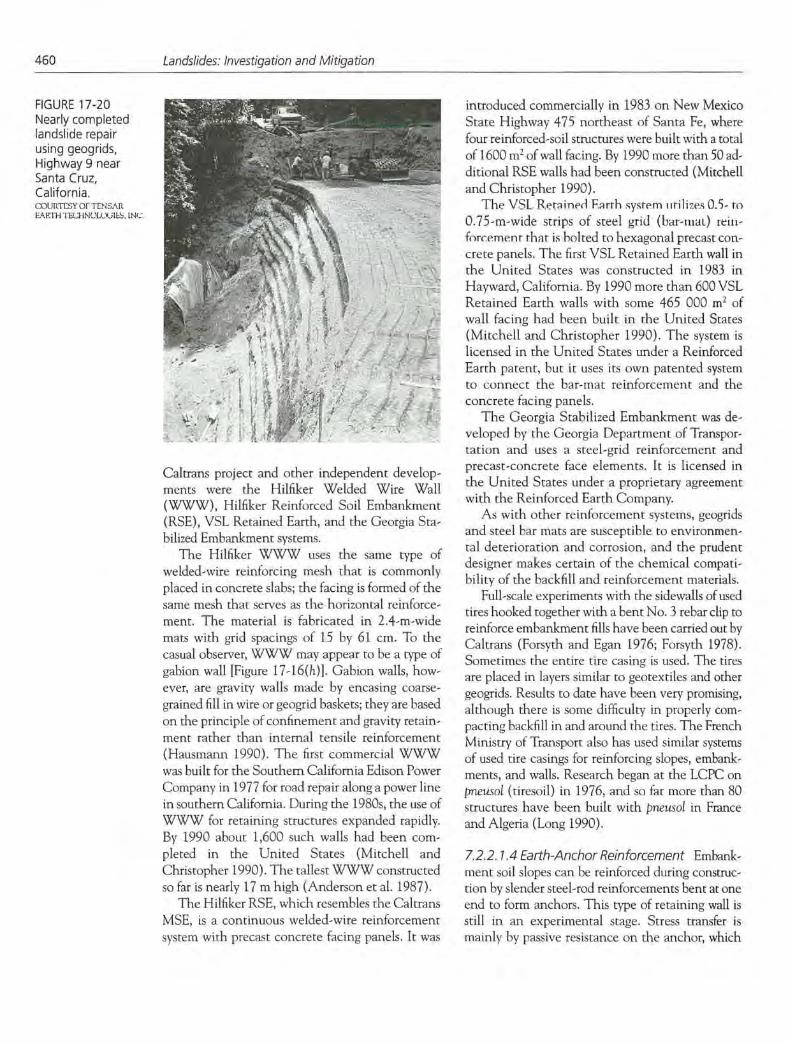
FIGURE 17-20 Nearly completed landslide repair using geogrids, Highway 9 near Santa Cruz, California.
;sTry orrL;,\
Caltrans project and other independent develop-inents were the Hilfiker Welded Wire Wall (WWW), Hilfiker Reinforced Soil Embankment (RSE), VSL Retained Earth, and the Georgia Sta-bilized Embankment systems.
The Hilfiker WWW uses the same type of welded-wire reinforcing mesh that is commonly placed in concrete slabs; the facing is formed of the same mesh that serves as the horizontal reinforce-ment. The material is fabricated in 2.4-rn-wide mats with grid spacings of 15 by 61 cm. To the casual observer, WWW may appear to be a type of gabion wall [Figure 17-16(h)]. Gahion walls, how-ever, are gravity walls made by encasing coarse-grained fill in wire or geogrid baskets; they are based on the principle of confinement and gravity retain-ment rather than internal tensile reinforcement (Hausmann 1990). The first commercial WWW was built for the Southern California Edison Power Company in 1977 for road repair along a power line in southern California. During the 1980s, the use of WWW for retaining structures expanded rapidly. By 1990 about 1,600 such walls had been com-pleted in the United States (Mitchell and Christopher 1990). The tallest WWW constructed so far is nearly 17 m high (Anderson et al. 1987).
The Hilfiker RSE, which resembles the Caltrans MSE, is a continuous welded-wire reinforcement system with precast concrete facing panels. It was
introduced commercially in 1983 on New Mexico State Highway 475 northeast of Santa Fe, where four reinforced-soil structures were built with a total of 1600 m2 of wall facing. By 1990 more than 50 ad-ditional RSE walls had been constructed (Mitchell and Christopher 1990).
The VSI_ Retained F.arrh system utilizes 0.5- to 0.75-rn-wide strips of steel grid (bar-inal) rein-forcement that is bolted to hexagonal precast con-crete panels. The first VSL Retained Earth wall in the United States was constructed in 1983 in Hayward, California. By 1990 more than 600 VSL Retained Earth walls with some 465 000 m2 of wall facing had been built in the United States (Mitchell and Christopher 1990). The system is licensed in the United States under a Reinforced Earth patent, but it uses its own patented system to connect the bar-mat reinforcement and the concrete facing panels.
The Georgia Stabilized Embankment was de-veloped by the Georgia Department of Transpor-tation and uses a steel-grid reinforcement and precast-concrete face elements. It is licensed in the United States under a proprietary agreement with the Reinforced Earth Company.
As with other reinforcement systems, geogrids and steel bar mats are susceptible to environmen-tal deterioration and corrosion, and the prudent designer makes certain of the chemical compati-bility of the backfill and reinforcement materials.
Full-scale experiments with the sidevalls of used tires hooked together with a bent No. 3 rehar clip to reinforce embankment fills have been carried out by Caltrans (Forsyth and Egan 1976; Forsyth 1978). Sometimes the entire tire casing is used. The tires are placed in layers similar to geotextiles and other geogrids. Results to date have been very promising, although there is some difficulty in properly com-pacting backfill in and around the tires. The French Ministry of Transport also has used similar systems of used tire casings for reinforcing slopes, embank-ments, and walls. Research began at the LCPC on pneusol (tiresoil) in 1976, and so far more than 80 structures have been built with pneusol in France and Algeria (Long 1990).
7.2.2. 1.4 Earth-Anchor Reinforcement Embank-inent soil slopes can he reinforced during construc-non by slender steel-rod reinforcements bent at one end to form anchors. This type of retaining wall is still in an experimental stage. Stress transfer is mainly by passive resistance on the anchor, which
Stabilization of Soil Slopes
461
implies that the system provides stability in the same manner as tied-back retaining structures and thus may not be a true reinforced-soil system (Mitchell and Villet 1987). However, the system is discussed here because it is analogous in placement technique to other methods of soil reinforcement in embankrnents and fills.
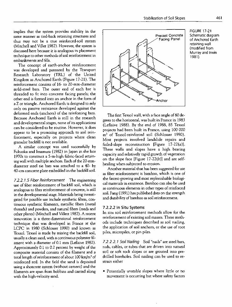
The concept of earth-anchor reinforcement was developed and patented by the Transport Research Laboratory (TRL) of the United Kingdom as Anchored Earth (Figure 17-21). The reinforcement consists of 16- to 20-mm-diameter mild-steel bars. The outer end of each bar is threaded to fit into concrete facing panels; the other end is formed into an anchor in the form of a Z or triangle. Anchored Earth is designed to rely only on passive resistance developed against the deformed ends (anchors) of the reinforcing bars. Because Anchored Earth is still in the research and developmental stages, none of its applications can be considered to be routine. However, it does appear to be a promising approach to soil rein-forcement, especially on projects where clean granular backfill is not available.
A similar concept was used successfully by Fukuoka and Irnamura (1982) in Japan in the late 1970s to construct a 5-m-high fabric-faced retain-ing wall with multiple anchors. Each of the 20-mm-diameter steel tie bars was attached to a 40- by 40-cm concrete plate embedded in the backfill soil.
7.2.2.1.5 Fiber Reinforcement The engineering use of fiber reinforcement of backfill soil, which is analogous to fiber reinforcement of concrete, is still in the developmental stage. Materials being investi-gated for possible use include synthetic fibers, con-tinuous synthetic filaments, metallic fibers (metal threads) and powders, and natural fibers (reeds and other plants) (Mitchell and Villett 1987). A recent innovation is a three-dimensional reinforcement technique that was developed in France at the LCPC in 1980 (Schiosser 1990) and known as Texsol. Texsol is made by mixing the backfill soil, usually a clean sand, with a continuous polyester fil-ament with a diameter of 0.1 mm (Leflaive 1982). Approximately 0.1 to 0.2 percent by weight of the composite material consists of the filament and a total length of reinforcement of about 100 km/rn3 of reinforced soil. In the field the sand is deposited using a shotcrete system (without cement) and the filaments are spun from bobbins and carried along with the high-velocity sand.
The first Texsol wall, with a face angle of 60 de-grees to the horizontal, was built in France in 1983 (Leflaive 1988). By the end of 1988, 85 Texsol projects had been built in France, using 100 000 m3 of Texsol-reinforced soil (Schlosser 1990). Most projects involved landslide repairs and failed-slope reconstruction [Figure 17-22(a)]. These walls and slopes have a high bearing capacity and relatively rapid growth of vegetation on the slope face [Figure 17-22(b)] and are self-healing when subjected to erosion.
Another material that has been suggested for use as fiber reinforcement is bamboo, which is one of the fastest-growing and most replenishable biologi-cal materials in existence. Bamboo can also be used as continuous elements in other types of reinforced soil. Fang (1991) has published data on the strength and durability of bamboo as soil reinforcement.
7.2.2.2 In Situ Systems In situ soil reinforcement methods allow for the reinforcement of existing soil masses. These meth-ods include techniques described as soil nailing, the application of soil anchors, or the use of root piles, micropiles, or pin piles.
7.2.2.2. 1 Soil Nailing Soil "nails" are steel bars, rods, cables, or tubes that are driven into natural soil or soft rock slopes or are grouted into. pre-drilled boreholes. Soil nailing can be used to re-strain either
Potentially unstable slopes where little or no movement is occurring but where safety factors
FIGURE 17-21 Schematic diagram of Anchored Earth retaining wall (modified from Murray and Irwin 1981).
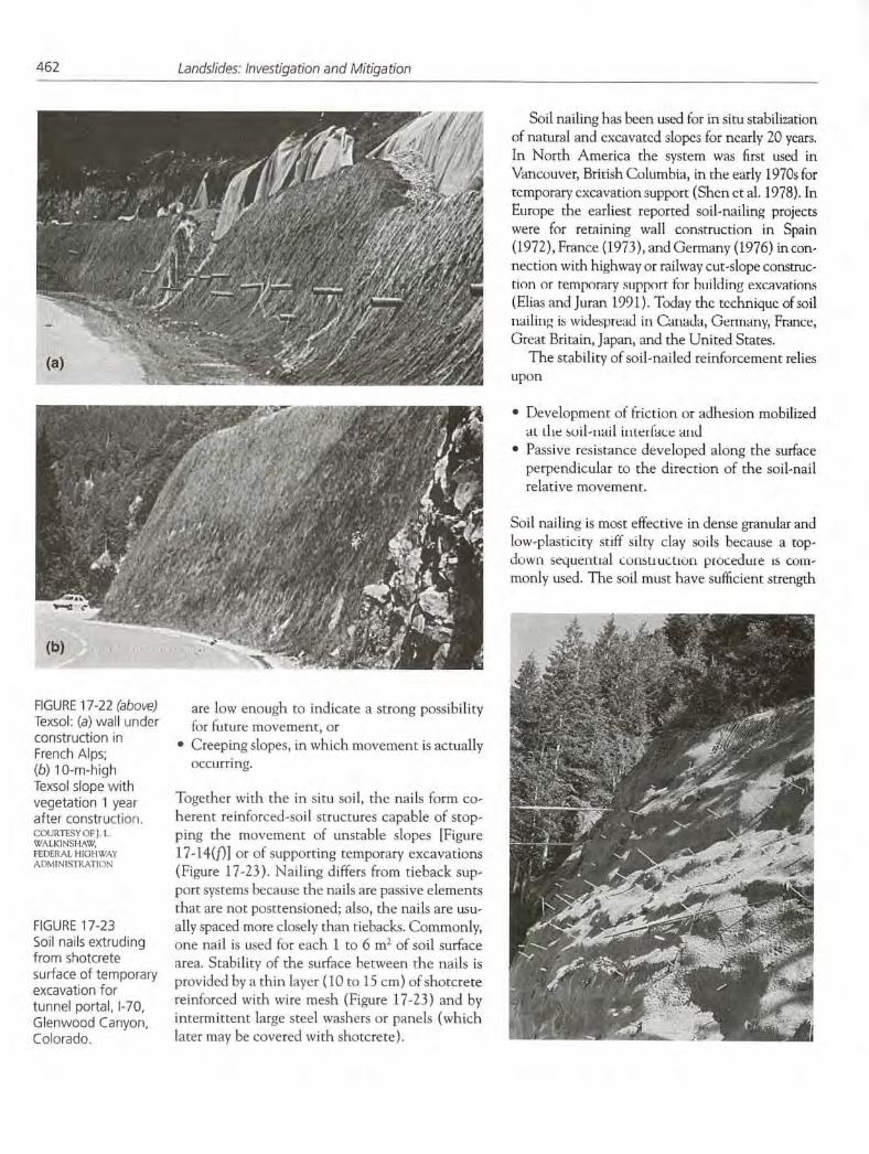
(b)
FIGURE 17-22 (above) are low enough to indicate a strong possibility Texsol: (a) wall under for future movement, or construction in Creeping slopes, in which movement is actually French Alps; (b) 1 0-rn-high occurring.
Texsol slope with vegetation 1 year Together with the in situ soil, the nails form co- after construction. herent reinforced-soil structures capable of stop- COURTESYOFJ.L ping the movement of unstable slopes [Figure WALKINSI LW, FEDERAL HIGHWAY 17-14(f)] or of supporting temporary excavations AD\IINNFRATION
(Figure 17-23). Nailing differs from tieback sup- port systems because the nails are passive elements that are not posttensioned; also, the nails are usu-
FIGURE 17-23 ally spaced more closely than tiebacks. Commonly, Soil nails extruding one nail is used for each 1 to 6 m2 of soil surface from shotcrete area. Stability of the surfce between the nails is surface of temporary provided by a thin layer (10 to 15 cm) of shotcrete excavation for tunnel portal, 1-70, reinforced with wire mesh (Figure 17-23) and by
Glenwood Canyon, intermittent large steel washers or panels (which Colorado. later may be covered with shotcrete).
462 Landslides: Investigation and Mitigation
Soil nailing has been used for in situ stabilization of natural and excavated slopes for nearly 20 years. In North America the system was first used in Vancouver, British Columbia, in the early 1970s for temporary excavation support (Shcn ct al. 1978), In Europe the earliest reported soil-nailing projects were for retaining wall construction in Spain (1972), France (1973), and Germany (1976) in con-nection with highway or railway cut-slope construc-tion or temporary smipporr for huilding excavations (Elias and Juran 1991). Today the technique of soil imailing is widespread in Canada, Germany, France, Great Britain, Japan, and the United States.
The stability of soil-nailed reinforcement relies upon
Development of friction or adhesion mobilized at Ilie soil-nail intel lace and Passive resistance developed along the surface perpendicular to the direction of the soil-nail relative movement.
Soil nailing is most effective in dense granular and low-plasticity stiff silty clay soils because a top-down sequential cuiIsu ucimoit piocedute is coin-monly used. The soil must have sufficient strength

Stabilization of Soil Slopes 463
to be able to stand in a vertical cut of about 2 in without failure or excessive deformation. Thus, soil nailing is generally not cost-effective or practical in loose granular soils and very soft clays (Mitchell and Christopher 1990). A high groundwater table may also present construction difficulties.
Suggestions for design of soil nailing include those by Elias and Juran (1991) and Byrne (1992). Soil-nailing systems are relatively flexible and thus should be resistant to seismic loading. However, knowledge of the dynamic behavior of soil-nailed structures is limited (Felio et al. 1990), and re-search is needed to develop procedures for earth-quake-resistant design. There are no proprietary restrictions on the use of soil nailing. However, some specific installation systems, nails, and fac-ings are patented.
The technique of soil nailing has been used mostly for stabilization of temporary excavations. There is some concern about the corrosion rate of the steel nails used in the process. However, new types of nails and coatings with high resistance to corrosion are being developed. To further increase confidence in the potential use of this method for permanent slope stabilization, additional research is being done on the field performance of soil-nailed structures. For example, in 1986 a 4-year,$4 million national research program named CLOUTERRE was initiated by the French Ministry of Transport to improve the status of knowledge and to develop de-sign and construction guidelines for soil-nailed re-tention systems (Schlosser and Unterreiner 1991; Schlosser et al. 1992). Plumelle and Schlosser (1991) presented the results of three full-scale ex-periments from this project.
A number of interesting case histories con-cerning the use of soil nailing for support of temp-orary excavations are available in both the French and U.S. literature [for example, Lambe and Hanson (1990)]. Denby et al. (1992) described the design, construction, and performance of a 23-rn-deep excavation in Seattle, Washington, that was successfully supported by a temporary soil-nailed wall. Collin et al. (1992) used a timber crib wall as the facing and helical anchors as the soil nails for a permanent earth retention system for a slope. There appear to be no published cases in which soil nailing has been used to stabilize active landslides or moving slopes.
A related system is anchored geosynthetics (spi-der netting) for slope stabilization (Figure 17-24).
Original Unstable Slope
Anchored ..... Spider Netting •....• eci
(in tension)..'
CP
Instead of shotcrete facing, a geotextile or geonet is attached to the nails, and as the nails are in-stalled, they pull the surface netting or geotextile into the soil, putting it into tension and at the same time constraining the near-surface soils in the slope (Koemer and Robins 1986). Design pro-cedures for anchored geosynthetic systems were described by Hryciw and Haji-Ahmad (1992).
7.2.2.2.2 Soil Anchors Stabilization of soil slopes with long prestressed anchors is increasing. Hutchinson (1984) described the stabilization of a landslide in glacial and glaciofluvial deposits in southern Wales (Figure 17-25). Before treatment in 1980, movements of as much as 15 mm/year were occurring at the head of the landslide and 2 to 5 mm/year was occurring at the toe. Because of severe spatial constraints, anchoring into the un-derlying bedrock proved to be the most effective stabilization measure.
FIGURE 17-24 (above) Schematic cross section of anchored geosynthetic "spider netting" used with soil nails or anchors to stabilize slope (modified from Koerner and Robins 1986).
FIGURE 17-25 Cross section of landslide in Quaternary deposits at Nantgarw, South Wales, United Kingdom (modified from Hutchinson 1977); slide has been stabilized by deep anchors in underlying bedrock.
Nails or Anchors
lure Surface
Taft Vale
0 10 20 m Trunk Road
Tension Crack
iff
Old Cardiff Quaternary
osi Fail .i Bedrock Anchors

464
Landslides: Investigation and Mitigation
FIGURE 17-26 Schematic cross section illustrating use of root piles for stabilization of slope (modified from Lizzi 1977).
7.2.2.2.3 Root Piles, Micropiles, and Pin Piles Another approach to reinforcement of in situ soils and soft rocks is the use of root piles, also known as micropiles or pin piles. Root piles are cast-in-place reinforced concrete piles with diameters ranging from 7.5 to 30 cm. In the smaller-diameter range, the insertions are provided with a central rein-forcing rod or steel pipe, whereas those with larger diameters may be provided with a reinforcing-bar cage bound with spiral reinforcement. A root-pile system forms a monolithic block of reinforced soil that extends below the critical failure surface (Figure 17-26). In contrast to soil nailing, the reinforcement provided by root piles is strongly influenced by their three-dimensional, rootlike geometric arrangement.
Reticulated Root Piles were originally devel-oped in the 1950s by Lizzi (1977) and were patented by the Italian firm Fondedile of Naples, which introduced and installed the system world-wide (mainly for underpinning). The original patents have now expired. Root piles have been used for slope stabilization only for the last 20 years, and most root-pile slope stabilization works have been constructed within the past 10 years. Aurilio (1987) described the use of root piles for stabilization of a landslide in California.
According to Bruce (1992a), during the past 20 years, U.S. practice using root piles has developed quite differently from the original European de-velopment. He provided details from some 20 pro-
Failure Surfac
jects that illustrate recent developments in U.S. pin-pile technology and discussed applications more specific to slope stabilization (Bruce 1992b). An interesting case history of the use of pin piles to control slope movements was described by Pearlman et al. (1992).
7.2.3 Vegetative and Biotechnical Stabilization
Slope stabilization provided directly by vegetation and by biotechnical slope protection (the use of vegetation combined with structural slope-stabilization elements) is reviewed briefly. The basic concepts of vegetative stabilization are not new, but recent research and development now enable more effective use of this technique than in the past. Additional information about bio-stabilization was provided by Gray (1970), Gray and Leiser (1982), Greenway (1987), and Wu (1994a, 1994b).
According to Wu (1994b), vegetation contri-butes to stability of slopes through (a) root rein-forcement and (b) rainfall interception and evapotranspiration, which reduce pore pressures. Case studies have shown that slope failures can be attributed to the loss of reinforcement provided by tree roots (Wu et al. 1979; Riestenberg and Sovonick-Dunford 1983; Riestenberg 1987). In spite of the fact that Greenway (1987), in his ex-tensive summary of the effects of vegetation on slope stability, included reports that vegetation tends to reduce slope stability, most researchers believe that vegetation is by far a positive aspect in the protection of slopes. Wu (1 994b) quantified this protection in terms of root reinforcement and reduction of soil moisture and pore pressures.
Research into the engineering role of vegeta-tion for slope stabilization by the Geotechnical Control Office of Hong Kong may be the most comprehensive such program in the world (Barker 1991). Especially notable are the root reinforce-ment studies conducted on vegetated slopes by Greenway et al. (1984), Greenway (1987), and Yin et al. (1988). In addition, the Geotechnical Manual for Slopes (Geotechnical Control Office 1984) includes information on the mechanical and hydrological effects of vegetation.
In recent years trees have been planted on many slopes worldwide to increase slope stability. One example is an element of a program to cor-

Stabilization of Soil Slopes 465
rect an embankment failure on 1-77 in Caidwell, Ohio. The slope was planted with black locust seedlings at a spacing of 1.2 m. The long-term ob-jective was to help reduce the soil moisture and to develop root stabilization. As of 1994 the project appeared to be successful.
Another recent well-documented case of the planting of tree seedlings occurred as part of the stabilization program for the Cucaracha landslide in the Gaillard Cut at the Panama Canal. The his-toric Cucaracha landslide was reactivated in 1986, almost blocking the canal (Berman 1991). As part of a comprehensive stabilization program, begin-ning in 1987 portions of the Cucaracha landslide and other landslide areas in the Canal Zone were planted with 60,000 fast-growing acacia and grnelina seedlings (Rivera 1991).
Stabilization of slopes by the combined use of vegetation and manufactured structural elements working together in an integrated manner is known as biotechnical slope stabilization. This relatively new concept is generally cost-effective as compared with the use of structures alone; it has increased the environmental compatibility of such treatments and allows the use of indigenous nat-ural materials. Although vegetative treatments alone are usually much less expensive than earth-retaining structures or other constructed slope protection systems, their effectiveness in arresting slope movement or preventing soil loss under ex-treme conditions may be much lower than that of the structures (Gray and Leiser 1982). Figure 17-27 presents different biotechnical slope stabi-lization and protection measures and examples.
Grasses and woody plants are used most often in biotechnical stabilization. They have a true re-inforcing function and should not be considered merely cosmetic adjuncts to the structure. They may be planted on a slope above a low retaining wall, or the interstices of the structure may be planted with vegetation whose roots bind together the soil within and behind the structure. The sta-bility of all types of retaining structures with open gridwork or tiered facings benefits from such veg-etation (Figure 17-27).
Gray and Sotir (1992) described the use of a crushed-rock-blanket toe berm combined with a brush-layer fill to stabilize a road cut along a scenic highway in Massachusetts. The crushed rock was placed at the toe of the cut; the brush-layer fill included stems and branches of plant
CATEGORY EXAMPLES
LlPlul @©TI1D©1fl©J Grass seeding
Conventional Sodding Plantings * Transplants
- * Live staking
Woody plants used Contour wattling as reInforcements * Brush layering and barriers to * Soft gabions soil movement * Brush mattress
Breast walls with
Piant/ structure slope face plantings
associations * Revetments with
99 slope face plantings * Tiered structures with
bench plantings
Woody plants grown * Live cribwalls
© In the frontal openings Vegetated rock gabions or Interstices of . Vegetated geogrid walls
c retaining structures * Vegetated breast walls
* Joint plantings !L!J Woody plants grown * Staked gablon matresser
in the frontal openings * Vegetated concrete or Interstices of block revetments porous revetments * Vegetated cellular grids
Reintorced" grass
IIrir ©©T@TO©I1I * Concrete gravity walls
Conventional * Cylinder pile walls
Structures * Tie back walls
species, such as willow and dogwood, that rooted readily from cuttings (Figure 17-28). The branches acted as reinforcement and as horizontal drains, and rooting of the embedded stems provided secondary stabilization.
Thomas and Kropp (1992) described a very in-teresting scheme using vegetation to stabilize a large debris-flow scar in California. At the time the paper was presented in 1992, the vegetation was quite effective and the project was considered by the authors to be a success.
7.2.4 Miscellaneous Stabilization Methods
The following miscellaneous stabilization meth-ods are discussed:
FIGURE 17-27 Classification of different biotechnical slope protection and erosion control measures (Gray and Sotir 1992). REPRINTED WITH PERMISSION OF AMERICAN SOCIETY OF CIVIL ENGINEERS
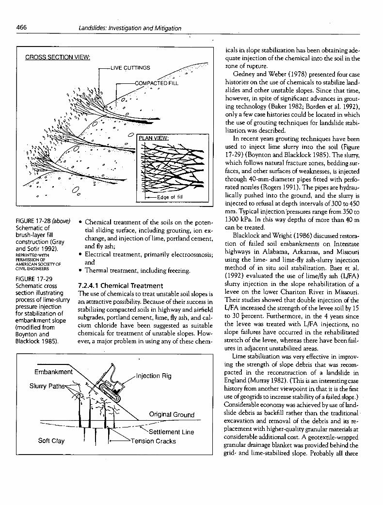
466
Landslides: Investigation and Mitigation
CROSS SECTION VIEW:
LIVE curnNGs
OMPACTED FILL . --.
a
: PLAN VIEW:
..........:.. :
0 —Edge of fill
Embankment Injection Rig
Slurry Path
Original Ground
--- —oft
'SettIement Line
T Clay ension Cracks
icals in slope stabilization has been obtaining ade-quate injection of the chemical into the soil in the zone of rupture.
Gedney and Weber (1978) presented four case histories on the use of chemicals to stabilize land- slides and other unstable slopes. Since that time, however, in spite of significant advances in grout-ing technology (Baker 1982; Borden et at. 1992), only a few case histories could be located in which the use of grouting techniques for landslide stabi-lization was described.
In recent years grouting techniques have been used to inject lime slurry into the soil (Figure 17-29) (Boynton and Blacklock 1985). The slurry, which follows natural fracture zones, bedding sur-faces, and other surfaces of weaknesses, is injected through 40-mm-diameter pipes fitted with perfo- rated nozzles (Rogers 1991). The pipes are hydrau-lically pushed into the ground, and the slurry is injected to refusal at depth intervals of 300 to 450 mm. Typical injection pressures range from 350 to 1300 kPa. In this way depths of more than 40 m can be treated.
Blacklock and Wright (1986) discussed restora-tion of failed soil embankments on Interstate highways in Alabama, Arkansas, and Missouri using the lime- and lime-fly ash-slurry injection method of in situ soil stabilization. Baez et al. (1992) evaluated the use of lime/fly ash (L/FA) slurry injection in the slope rehabilitation of a levee on the lower Chariton River in Missouri. Their studies showed that double injection of the L/FA increased the strength of the levee soil by 15 to 30 bercent. Furthermore, in the 4 years since the levee was treated with L/FA injections, no slope failures have occurred in the rehabilitated stretch of the levee, whereas there have been fail-ures in adjacent unstabilized areas.
Lime stabilization was very effective in improv-ing the strength of slope debris that was recom- pacted in the reconstruction of a landslide in England (Murray 1982). (This is an interesting case history from another viewpoint in that it is the first use of geogrids to increase stability of a failed slope.) Considerable economy was achieved by use of land-slide debris as backfill rather than the traditional excavation and removal of the debris and its re-placement with higher-quality granular materials at considerable additional cost. A geotextile-wrapped granular drainage blanket was provided behind the grid- and lime-stabilized slope. Probably all three
FIGURE 17-28 (above) Schematic of brush-layer fill construction (Gray and Sotir 1992). REPRINTED WITH PERMISSION OF AMERICAN SOCIETY OF CIVIL ENGINEERS
FIGURE 17-29 Schematic cross section illustrating process of lime-slurry pressure injection for stabilization of embankment slope (modified from Boynton and Blacklock 1985).
Chemical treatment of the soils on the poten-tial sliding surface, including grouting, ion ex-change, and injection of lime, portland cement, and fly ash; Electrical treatment, primarily electroosmosis; and Thermal treatment, including freezing.
7.2.4.1 Chemical Treatment The use of chemicals to treat unstable soil slopes is an attractive possibility. Because of their success in stabilizing compacted soils in highway and airfield subgrades, portland cement, time, fly ash, and cal-cium chloride have been suggested as suitable chemicals for treatment of unstable slopes. How-ever, a major problem in using any of these chem-

Stabilization of Soil Slopes
467
treatment techniques (drainage, time stabilization, and geosynthetic reinforcement) contributed to the success of the project.
7.2.4.2 Electroosmosis Another special technique that increases the shear-ing strength of soils in situ is electroosmosis. The classic papers on electroosmosis were published by Casagrande (1948, 1952, 1953). There are a num-ber of case histories in the literature in which elec-troosmosis was used to stabilize embankment foundations; these were summarized by Holtz (1989). However, the classic application of elec-troosmosis has been to stabilize landslides and slopes. An early case history was reported by Casagrande et al. (1961) in which electroosmosis was used to stabilize a 30-m-high slope in organic silt that had developed serious instability during con-struction of a pier for the Little Pic River bridge on the Trans-Canada Highway in Ontario. Casagrande et al. (1981) also described the use of electroosmosis to stabilize a slope for an 80-m-deep excavation for the core trench of a dam in British Columbia.
As summarized by Veder (1981), Griffin de-scribed the use of electroosmosis to stabilize a 30-rn-high slope of loose, sensitive silt above the Kootenay Channel power plant in British Columbia, Canada. As a result of electroosmosis, the slope, which originally was barely stable at 1V:5H, was able to be safely steepened to 1V:2H.
In previous discussion concerning electroos-motic dewatering (Section 6.2.3.1), it was noted that Lo et al. (1991a, 1991b) developed special electrodes that allow free water flow without pumping. In field tests conducted on the soft, sen-sitive Leda clay of eastern Canada, undrained shear strength increased uniformly by about 50 percent in a period of 32 days throughout the depth of the electrodes. Because no pumping was required, both installation and electricity costs were significantly lower than those in previous electroosmosis drainage installations.
7.2.4.3 Thermal Treatment As reported by Gedney and Weber (1978), exper-iments were carried out in the former Soviet Union for a number of years using thermal treat-ment of clays and loessial soils. The technique was used by Romanian engineers for stabilization of clay slopes (Beles 1957). High temperatures dry out the soil and tend to fuse fine-grained particles,
which leads to permanent increases in shear strength and consequent increases in slope stabil-ity. However, the high cost of thermal treatment precludes its use on all but the most experimental slope remediation problems.
Ground freezing has developed in recent years to be a very effective technique for temporary sta-bilization of large excavations and tunnels. One of the most complete treatises on ground freezing is by Jessberger (1979).
Allen, T. A., B. R. Christopher, and R. D. Holtz. 1992. Performance of a 12.6 m High Geotextile Wall in Seattle, Washington. In Geosynthetic Reinforced Soil Retaining Walls, Proceedings of the International Symposium, Denver (J.T.H. Wu, ed.), A.A. Bal-kema, Rotterdam, Netherlands, pp. 8 1-100.
Allen, T A., and R. D. Holtz. 1991. Design of Retaining Walls Reinforced with Geosynthetics. In Proc., Geotechnical Engineering Congress 1991, Boulder, Colorado (F. G. McLean, D. A. Campbell, and D. W. Harris, eds.), Geotechnical Special Publication 27, American Society of Civil Engineers, New York, pp. 970-987.
Allen, T.M. 1991. Determination of Long-Term Tensile Strength of Geosynthetics: A State-of-the-Art Review. In Proc., Geosynthetics '91 Conference, Atlanta, Industrial Fabrics Association Interna-tional, St. Paul, Minn., Vol. 1, pp. 351-379.
Anderson, R. L., K. D. Sharp, and 0. T Harding. 1987. Performance of a 50-Foot High Welded Wire Wall. In Soil Improvement—A Ten Year Update (J. P. Welsh, ed.), Geotechnical Special Publication 12, American Society of Civil Engineers, New York, pp. 280-308.
Arutjunyan, R. N. 1988. Prevention of Landslide Slope Process by Vacuuming Treatment of Dis-consolidated Soils. In Proc., Fifth International Symposium on Landslides, Lausanne, July 10-15, A.A. Balkema, Rotterdam, Netherlands, Vol. 2, pp. 835-837.
Aurilio, G. 1987. In-Situ Ground Reinforcement with Root Piles. In Soil Improvement—A Ten Year Update (J. P. Welsh, ed.), Geotechnical Special Publication 12, American Society of Civil Engi-neers, New York, pp. 270-279.
Baez, J. I., R. H. Bordeau, and J. H. Henry. 1992. Rehabilitation of Lower Chariton River Levee by Lime/Flyash Slurry Injection. In Transportation Research Record 1310, TRB, National Research Council, Washington, D.C., pp. 117-125.
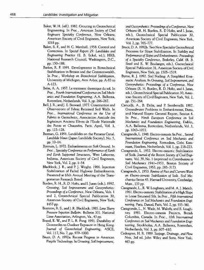
468
Landslides: Investigation and Mitigation
Baker, W. H. (ed.). 1982. Grouting in Geotechnical Engineering. In Proc., American Society of Civil Engineers Specialty Conference, New Orleans, American Society of Civil Engineers, New York, 1018 pp.
Baker, R. F., and H. C. Marshall. 1958. Control and Correction. In Special Report 29: Landslides and Engineering Practice (F. B. Eckel, ed.), HRB, National Research Council, Washington, D.C., pp. 150-188.
Barker, R. F. 1991. Developments in Biotechnical Stabilization in Britain and the Commonwealth. In Proc., Workshop on Biotechnical Stabilization, University of Michigan, Ann Arbor, pp. A-83 to A- 123.
Beles, A. A. 1957. Le traitment thermique du sol. In Proc., Fourth International Conference on Soil Mech-anics and Foundation Engineering, A.A. Balkema, Rotterdam, Netherlands, Vol. 3, pp. 266-267.
Bell,J. R., and J. E. Steward. 1977. Construction and Observations of Fabric Retained Soil Walls. In Proc., International Conference on the Use of Fabrics in Geotechnics, Association Amicale des Ingenieurs Anciens Elèves de l'Ecole Nationale des Ponts et Chaussées, Paris, April, Vol. 1, pp. 123-128.
Berman, G. 1991. Landslides on the Panama Canal. Landslide News (Japan Landslide Society), No. 5, pp.10-14.
Bjerrum, L. 1972. Embankments on Soft Ground. In Proc., Specialty Conference on Performance of Earth and Earth Supported Structures, West Lafayette, Indiana, American Society of Civil Engineers, New York, Vol. 2, pp. 1-54.
Blacklock, J. R., and P. J. Wright. 1986. Injection Stabilization of Failed Highway Embankments. Presented at 65th Annual Meeting of the Trans-portation Research Board.
Borden, R. H., R. D. Holtz, and I. Juran (eds.). 1992. Grouting, Soil Improvement and Geosynthetics: Proceedings of a Conference, New Orleans, Vols. 1 and 2, Geotechnical Special Publication 30, American Society of Civil Engineers, New York, 1453 pp.
Boynton, R. S., and J. R. Blacklock. 1985. Lime Slurry Pressure Injection Bulletin. Bulletin 331. National Lime Association, Arlington, Va., 43 pp.
Brand, E. W., and P. L. R. Pang. 1991. Durability of Geotextiles to Outdoor Exposure in Hong Kong. Journal of Geotechnical Engineering, ASCE, Vol. 117, No. 7, pp. 979-1000.
Bruce, D. A. 1992a. Recent Progress in American Pinpile Technology. In Grouting, Soil Improvement,
and Geosynthetics: Proceedings of a Conference, New Orleans (R. H. Borden, R. D Holtz, and I. Juran, eds.), Geotechnical Special Publication 30, American Society of Civil Engineers, New York, Vol. 2, pp. 765-777.
Bruce, D. A. 1992b. Two New Specialty Geotechnical Processes for Slope Stabilization. In Stability and Performance of Slopes and Embankments: Proceedings of a Specialty Conference, Berkeley, Calif. (R. B. Seed and R. W. Boulariger, eds.), Geotechnical Special Publication 31, American Society of Civil Engineers, New York, pp. 1505-15 19.
Byrne, R. J. 1992. Soil Nailing: A Simplified Kine-matic Analysis. In Grouting, Soil Improvement, and Geosynthetics: Proceedings of a Conference, New Orleans (R. H. Borden, R. D. Holtz, and I. Juran, eds.), Geotechnical Special Publication 30, Amer-ican Society of Civil Engineers, New York, Vol. 2, pp. 75 1-764.
Cancelli, A., B. Delia, and P. Sembenelli. 1987. Groundwater Problems in Embankments, Dams, and Natural Slopes: General Report, Session 4. In Proc., Ninth European Conference on Soil Mechanics and Foundation Engineering, Dublin, A.A. Balkema, Rotterdam, Netherlands, Vol. 3, pp. 1043-1072.
Casagrande, L. 1948. Electro-osmosis. In Proc., Second International Conference on Soil Mechanics and Foundation Engineering, Rotterdam, Gebr. Kees- maat, Haarlem, Netherlands, Vol. 1, pp. 218-223.
Casagrande, L. 1952. Electro-osmotic Stabilization of Soils. Journal of the Boston Society of Civil Engi- neers, Vol. 39, No. 1 (reprinted in Contributions to Soil Mechanics 1941-1953, Boston Society of Civil Engineers, 1953, pp. 285-3 17).
Casagrande, L. 1953. Review of Past and Current Work on Electro-osmotic Stabilization of Soils. Soil Me-chanics Series 45. Harvard University, Cambridge, Mass., 133 pp.
Casagrande, L., R. W. Loughney, and M. A. J. Matich. 1961. Electro-osmotic Stabilization of a High Slope in Loose Saturated Silt. In Proc., Fifth International Conference on Soil Mechanics and Foundation Engi-neering, Paris, Dunod, Paris, Vol. 2, pp. 555-561.
Casagrande, L., N. Wade, M. Wakely, and R. Lough-ney. 1981. Electro-osmosis Projects, British Columbia, Canada. In Proc., 10th International Conference on Soil Mechanics and Foundation Engi-neering, Stockholm, A.A. Balkema, Rotterdam, Netherlands, Vol. 3, pp. 607-610.
Cedergren, H. R. 1989. Seepage, Drainage, and Flow Nets, 3rd ed. John Wiley and Sons, New York, 465 pp.
Stabilization of Soil Slopes
469
Chang, J. C., J. B. Hannon, and R. A. Forsyth. 1977. Pull Resistance and Interaction of Earthwork Reinforcement and Soil. In Transportation Research Record 640, TRB, National Research Council, Washington, D.C., pp. 1-7.
Christopher, B. R., S. A. Gill, J. P. Giroud, I. Juran, J. K. Mitchell, F Schlosser, and J. Dunnicliff. 1990. Reinforced Soil Structures, Vol. 1: Design and Construction Guidelines. Report FHWA-RD-89-043. FHWA, U.S. Department of Transportation,
287 pp. Christopher, B. R., and R. D. Holtz. 1985. Geotextile
Engineering Manual. Report FHWA-TS-86-203. FHWA, U.S. Department of Transportation, 1024 pp.
Christopher, B. R., andR. D. Holtz. 1989. Geotextile Design and Construction Guidelines. Report FHWA-HI-90-001. FHWA, U.S. Department of Transportation, 334 pp.
Collin, J. G., M. A. Gabr, and A. G. MacKinnon. 1992. Timber Crib-Faced Soil-Nailed Retaining Wall. In Stability and Performance of Slopes and Embankments: Proceedings of a Specialty Conference, Berkeley, Calif. (R. B. Seed and R. W. Boulanger, eds.), Geotechnical Special Publication 31, Amer-ican Society of Civil Engineers, New York, pp. 1457-1463.
Collotta, T., V. Manassero, and P. C. Moretti. 1988. An Advanced Technology in Deep Drainage of Slopes. In Proc., Fifth International Symposium on Landslides, Lausanne, A.A. Balkema, Rotterdam, Netherlands, Vol. 2, pp. 887-892.
Committee on Ground Failure Hazards. 1985. Reducing Losses from Landsliding in the (Jnited States. Commission on Engineering and Technical Systems, National Research Council, Washington, D.C., 41 pp.
Craig, D. J., and I. Gray. 1985. Groundwater Lowering by Horizontal Drains. GCO Publication 2-85. Geotechnical Control Office, Engineering Devel-opment Department, Hong Kong, 123 pp.
Denby, G., D. Argo, and D. Campbell. 1992. Soil Nail Design and Construction, Swedish Hospital Parking Garage, Seattle, Washington. Presented at Seminar on Soil Nailing and Reinforced Soil Walls, Seattle, American Society of Civil Engineers, 11 pp.
Edil, T. B. 1992. Landslide Cases in the Great Lakes: Issues and Approaches. In Transportation Research Record 1343, TRB, National Research Council, Washington, D.C., pp. 87-94.
Elias, V. 1990. Durability/Corrosion of Soil Reinforced Structures. Report FHWA-RD-89-186. FHWA, U.S. Department of Transportation, 163 pp.
Elias, V., and I. Juran. 1991. Soil Nailing for Stabili-zation of Highway Slopes and Excavations. Report FHWA-RD-89-198. FHWA, U.S. Department of Transportation, 210 pp.
Fang, H.Y. 1991. The Use of Bamboo Inclusions for Earth Reinforcement. In Proc., Workshop on Biotechnical Stabilization, University of Michigan, Ann Arbor, pp. 33-62.
Felio, G., M. Vucetic, M. Hudson, P. Bárar, and R. Chapman. 1990. Performance of Soil Nailed Walls During the October 17 1989 Loma Prieta Earthquake. In Proc., 43rd Canadian Geotechnical Conference, Quebec City, Canadian Geotechnical Society, Rexdale, Ontario, Vol. 1, pp. 165-173.
Forsyth, R. A. 1978. Alternative Earth Reinforcements. In Proc., Symposium on Earth Reinforcement, Pittsburgh, American Society of Civil Engineers, New York, pp. 358-370.
Forsyth, R. A., and D.A. Bieber. 1984. La Honda Slope Repair with Grid Reinforcement. In Proc., International Symposium on Polymer Grid Reinforce-ment in Civil Engineering, London, pp. 54-58.
Forsyth, R. A., and J. P. Egan. 1976. Use of Waste Materials in Embankment Construction. In Trans-portation Research Record 593, TRB, National Research Council, Washington, D.C., pp. 3-8.
Fukuoka, M., and Y. Imamura. 1982. Fabric Retaining Walls. In Proc., Second International Conference on Geotextiles, Las Vegas, Industrial Fabrics Association International, St. Paul, Minn., Vol. 2, pp. 5 75-580.
Gedney, D. S., and W. G. Weber. 1978. Design and Construction of Soil Slopes. In Special Report 176: Landslides: Analysis and Control (R. L. Schuster and R. J. Krizek, eds.), TRB, National Research Council, Washington, D.C., Chapter 8, pp. 172-191.
Geotechnical Control Office. 1984. Geotechnical Manual for Slopes, 2nd ed. Public Works Depart-ment, Hong Kong, 295 pp.
Gillon, M. D., C. J. Graham, and G. G. Grocott. 1992. Low Level Drainage Works at the Brewery Creek Slide. In Proc., Sixth International Symposium on Landslides, Christchurch, New Zealand, A.A. Balkema, Rotterdam, Netherlands, Vol. 1, pp. 715-727.
Gould, J. P. 1990. Earth Retaining Structures-Developments through 1970. In Design and Performance of Earth Retaining Structures: Pro-ceedings of a Conference, Ithaca, N.Y., Geotechnical Special Publication 25, American Society of Civil Engineers, New York, pp. 8-21.
Gray, D. H. 1970. Effect of Forest Clear-Cutting on the Stability of Natural Slopes. Bulletin of the

470
Landslides: Investigation and Mitigation
Association of Engineering Geologists, Vol. 7, No. 1, pp. 45-66.
Gray, D. H., and A. T. Leiser. 1982. Biotechnical Slope Protection and Erosional Control. Van Nostrand Reinhold, New York, 271 pp.
Gray, D. H., and R. B. Sotir. 1992. Biotechnical Stabilization of Cut and Fill Slopes. In Stability and Performance of Slopes and Embankments: Proceedings of a Specialty Conference, Berkeley, Calif. (R. B. Seed and R. W. Boulanger, eds.), Geotechnical Special Publication 31, American Society of Civil Engineers, New York, pp. 1395-14 10.
Greenway, D. R. 1987. Vegetation and Slope Stability. In Slope Stability (M. G. Anderson and K. S. Richards, eds.), John Wiley, New York, pp. 187-230.
Greenway, D. R., M. G. Anderson, and K. C. Brian-Boys. 1984. Influence of Vegetation on Slope Stability in Hong Kong. In Proc., Fourth International Symposium on Landslides, Toronto, A.A. Balkema, Rotterdam, Netherlands, Vol. 1, pp. 399-404.
Greer, D. J., and H. A. Mathis. 1992. Proposed Correction of a Landslide for Relocation of Ken- tucky Highway 9 Using a Deep Drainage Gallery. In Transportation Research Record 1343, TRB, National Research Council, Washington, D.C., pp. 95-100.
Gress, J.C. 1992. Siphon Drain: A Technic for Slope Stabilization. In Prqç., Sixth International Sym- posium on Landslides, Christchurch, New Zealand, A.A. Balkema, Rotterdam, Netherlands, Vol. 1, pp. 729-734.
Hausmann, M. R. 1990. Engineering Principles of Ground Modification. McGraw-Hill, New York, 632 pp.
Holtz, R. D. 1978. Special Applications. In Proc., Symposium on Earth Reinforcement, Pittsburgh, American Society of Civil Engineers, New York, pp. 77-97.
Holtz, R. D. 1989. NCHRP Synthesis of Highway Practice 147: Treatment of Problem Foundations for Highway Embankments. TRB, National Research Council, Washington, D.C., pp. 14-16.
Holtz, R. D., M. B. Jamiolkowski, R. Lancellotta, and R. Pedroni. 1991. Prefabricated Vertical Drains: Design and Performance. CIRIA Series. Butterworth-Heineman, London, 131 pp.
Hovland, H. J., and D. F. Willoughby. 1982. Slide Stabilization at the Geyser's Power Plant. In Application of Walls to Landslide Control Problems, Proceedings of two sessions, American Society of Civil Engineers National Convention, Las Vegas (R. B. Reeves, ed.), American Society of Civil Engineers, New York, N.Y., pp. 77-92.
Hryciw, R. D., and K. Haji-Ahmad. 1992. Design of Anchored Geosynthetic Systems for Slope Stabilization. In Stability and Performance of Slopes and Embankments, Proceedings of a Specialty Conference, Berkeley, Calif. (R. B. Seed and R. W. Boulanger, eds.), Geotechnical Special Publication 31, American Society of Civil Engineers, New York, pp. 1464-1480.
Humphrey, D. N., and W. P. Manion. 1992. Properties of Tire Chips for Lightweight Fill. In Grouting, Soil Improvement, and Geosynthetics: Proceedings of a Conference, New Orleans (R. H. Borden, R. D. Holtz, and I. Juran, eds.), Geotechnical Special Publication 30, American Society of Civil Engi-neers, New York, Vol. 2, pp. 1346-1355.
Hutchinson, J. N. 1977. Assessment of the Effec-tiveness of Corrective Measures in Relation to Geologic Conditions and Types of Slope Move-ment. Bulletin of the Association of Engineering Geologists, Vol. 16, pp. 13 1-155.
Hutchinson, J. N. 1984. Landslides in Britain and Their Countermeasures. Journal of Japan Landslide Society, Vol. 21, No. 1, pp. 1-24.
Isenhower, W. M. 1987. Slope Failures in San Antonio, Texas (preprint). Presented at 12th Southwest Geotechnical Engineers Conference, Scotsdale, Arizona, pp. 1-26.
Isenhower, W. M., S. G. Wright, and M. K. Kayyal. 1989. Design Procedures for Slide Suppressor Walls. In Transportation Research Record 1242, TRB, National Research Council, Washington, D.C., pp. 15-21.
Iwasaki, K., and S. Watanabe. 1978. Reinforcement of Railway Embankments in Japan. In Proc., Symposium on Earth Reinforcement, Pittsburgh, American Society of Civil Engineers, New York, pp. 473-500.
Jessberger, H. L. (ed.). 1979. Ground Freezing. Devel-opments in Geotechnical Engineering, Vol. 26. Elsevier, Amsterdam, 552 pp.
Jones, C. J. F. P. 1978. The York Method of Reinforced Earth Construction. In Proc., Symposium on Earth Reinforcement, Pittsburgh, American Society of Civil Engineers, New York, pp. 501-527.
Jones, C. J. F. P. 1985. Earth Reinforcement and Soil Structures. Butterworths, London, 183 pp.
Koemer, R. M. 1990. Designing with Geosynthetics, 2nd ed. Prentice-Hall, Englewood Cliffs, N.J., 625 pp.
Koemer, R. M., and J. C. Robins. 1986. In Situ Stabilization of Soil Slopes using Nailed Geo-synthetics. In Proc., Third International Conference on Geotextiles, Csterreichischer Ingenieur-und
Stabilization of Soil Slopes 471
Architektenverein, Vienna, Austria, Vol. 2, pp. 395-400.
Kropp, A., and M. Thomas. 1992. Partial Landslide Repair by Buttress Fill. In Transportation Research Record 1343, TRB, National Research Council, Washington, D.C., pp. 108-113.
Lambe, P. C., and L. A. Hanson (eds.). 1990. Design and Performance of Earth Retaining Structures: Proceedings of a Conference, Ithaca, N.Y., Geo-technical Special Publication 25, American Society of Civil Engineers, New York, 904 pp.
Lee, K. L., B. D. Adams, and J. M. J. Vagneron. 1973. Reinforced Earth Retaining Walls. Journal of the Soil Mechanics and Foundations Division, ASCE, Vol. 99, No. SM10, pp. 745-764.
Leflaive, E. 1982. The Reinforcement of Granular Materials with Continuous Fibers (in French). In Proc., Second International Conference on Geo-textiles, Las Vegas, Industrial Fabrics Association International, St. Paul, Minn., Vol.3, pp. 72 1-726.
Leflaive, E. 1988. Texsol: Already More Than 50 Successful Applications. In Proc., International Symposium on Theory and Practice of Earth Reinforcement, Kyushu, Japan, A.A. Balkema, Rotterdam, Netherlands, pp. 54 1-545.
Lew, K. V., and J. Graham. 1988. River Bank Stabil-ization by Drains in Plastic Clay. In Proc., Fifth International Symposium on Landslides, Lausanne, A.A. Balkema, Rotterdam, Netherlands, Vol. 2, pp. 939-944.
Lizzi, F 1977. Practical Engineering in Structurally Complex Formations (the In Situ Reinforced Earth). In Proc., International Symposium on the Geotechnics of Structurally Complex Formations, Capri, Italy, Associazione Geotecnica Italiana.
Lo, K. Y., H. S. Ho, and I. I. Inculet. 1991a. Field Test of Electroosmotic Strengthening of Soft Sensitive Clays. Canadian Geotechnical Journal, Vol. 28, pp. 74-83.
Lo, K. Y., 1. I. Inculet, and H. S. Ho. 1991b. Electro-osmotic Strengthening of Soft Sensitive Clays. Canadian GeotechnicalJournal, Vol. 28, pp. 62-73.
Long, N. T. 1990. Le Pneusol. Etudes et Recherches des Laboratoires des Ponts et Chaussées, Série Geotechnique GT44. Laboratoire Central des Ponts et Chaussées, Paris, 76 pp.
Millet, R. A., G. M. Lawton, P. C. Repetto, and V. K. Garga. 1992. Stabilization of Tablachaca Dam. In Stability and Performance of Slopes and Embank-ments: Proceedings of a Specialty Conference (R. B. Seed and R. W. Boulanger, eds.), Geotechnical Special Publication 31, American Society of Civil Engineers, New York, pp. 1365-138 1.
Mitchell, J. K., and B. R. Christopher. 1990. North American Practice in Reinforced Soil Systems. In Design and Performance of Earth Retaining Structures: Proceedings of a Conference, Ithaca, N.Y. (P. C. Lambe and L. A. Hanson, eds.), Geotechnical Special Publication 25, American Society of Civil Engineers, New York, pp. 322-346.
Mitchell, J. K., and W. C. B. Villet. 1987. NCHRP Report 290: Reinforcement of Earth Slopes and Embankments. TRB, National Research Council, Washington, D.C., 323 pp.
Morgenstern, N. R. 1982. The Analysis of Wall Supports to Stabilize Slopes. In Application of Walls to Landslide Control Problems, Proceedings of two sessions, American Society of Civil Engineers National Convention, Las Vegas (R. B. Reeves, ed.), American Society of Civil Engineers, New York, N.Y., pp. 19-29.
Murray, R. T. 1982. Fabric Reinforcement of Embankments and Cuttings. In Proc., Second International Conference on Geotextiles, Las Vegas, Industrial Fabrics Association International, St. Paul, Minn., Vol. 3, pp. 701-713.
Murray, R. T., and M. J. Irwin. 1981. A Preliminary Study of TRRL Anchored Earth. Supplementary Report 674. U.K. Transport and Road Research Laboratory, Crowthorne, Berkshire, England.
Nelson, D. S., and W. L. Allen. 1974. Sawdust and Lightweight Fill Material. Report FHWA-RD-74-502. FHWA, U.S. Department of Transportation, 24 pp. (reprinted in Highway Focus, Vol. 6, No.3, pp. 53-66).
Nethero, M. F 1982. Slide Controlled by Drilled Pier Walls. In Application of Walls to Landslide Control Problems, Proceedings of two sessions, American Society of Civil Engineers National Convention, Las Vegas (R. B. Reeves, ed.), pp. 6 1-76.
Oakland, M. W., and J. L. A. Chameau. 1984. Finite Element Analysis of Drilled Piers Used for Slope Stabilization. In Laterally Loaded Deep Founda-tions: Analysis and Performance, Special Technical Publication 835, ASTM, Philadelphia, Pa., pp. 182-193.
O'Rourke, T. D, and C. J. F P. Jones. 1990. Overview of Earth Retention Systems: 1970-1990. In Design and Performance of Earth Retaining Structures: Proceedings of a Specialty Conference, Ithaca, N.Y. (P. C. Lambe and L. A. Hanson, eds.), Geotechnical Special Publication 25, American Society of Civil Engineers, New York, pp. 22-5 1.
Palladino, D. J., and R. B. Peck. 1972. Slope Failures in an Overconsolidated Clay, Seattle, Washington. Geotechnique, Vol. 22, No. 4, pp. 563-595.
472
Landslides: Investigation and Mitigation
Peariman, S. L., B. D. Campbell, and J. L. Withiam. 1992. Slope Stabilization Using In-Situ Earth Reinforcements. In Stability and Performance of Slopes and Embankments: Proceedings of a Confer-ence, Berkeley, Calif. (R. B. Seed and R. W. Bou-langer, eds.), Geotechnical Special Publication 31, American Society of Civil Engineers, New York, pp. 1333-1348.
Peck, R. B., and H. 0. Ireland. 1953. Investigation of Stability Problems. Proc., American Railway Engineering Association, Vol. 54, pp. 1116-1128.
Plumelle, C., and F Schlosser. 1991. Three Full-Scale Experiments of French Project on Soil Nailing: CLOUTERRE. In Transportation Research Record 1330, TRB, National Research Council, Wash-ington, D.C., pp. 80-86.
Read, J., T. Dodson, and J. Thomas. 1991. Experi-mental Project Use of Shredded lires for Lightweight Fill: Post-Construction Report. FHWA Experimen-tal Project No. 1. Oregon Department of Transpor-tation, Salem, 31 pp.
Reagan, J., and W. Jutkowfsky. 1985. Applications and Performance of Horizontal Drain Projects in New York State. Soil Mechanics Bureau, New York Department of Transportation, Albany, 26 pp.
Reese, L. C., S. T. Wang, and J. L. Fouse. 1992. Use of Drilled Shafts in Stabilizing a Slope. In Stability and Performance of Slopes and Embankments: Proceedings of a Conference, Berkeley, Calif. (R. B. Seed and R. W. Boulanger, eds.), Geotechnical Special Publication 31, American Society of Civil Engineers, New York, pp. 1318-1332.
Riestenberg, M. M. 1987. Anchoring of Thin Collu-vium on Hillslopes by Roots of Sugar Maple and White Ash. Ph.D. dissertation. University of Cin-cinnati, Cincinnati, Ohio.
Riestenberg, M. M., and S. Sovonick-Dunford. 1983. The Role of Woody Vegetation in Stabilizing Slopes in the Cincinnati Area, Ohio. Geological Society of America Bulletin, Vol. 94, pp. 506-5 18.
Ritchie, A. M. 1963. Evaluation of Rockfall and Its Control. In Highway Research Record 17, HRB, National Research Council, Washington, D.C., pp. 13-28.
Rivera, R. 1991. Reforestation Program-Gaillard Cut. Panama Canal Commission Report No. 1, 12 pp. plus appendix.
Robinson, C. S. 1979. Geologic Constraints on the Vail Pass Project. In Highway Research Record 717, HRB, National Research Council, Washington, D.C., pp. 6-14.
Rogers, C. D. F. 1991. Slope Stabilization Using Lime. In Proc., International Conference on Slope Stability
Engineering: Developments and Applications, Insti-tution of Civil Engineers, Isle of Wight, Thomas Telford, Ltd., pp. 335-492.
Rollins, K. M., and R. L. Rollins. 1992. Case Histories of Landslide Stabilization Using Drilled Shaft Walls. In Transportation Research Record 1343, TRB, National Research Council, Washington, D.C., pp. 114-122.
Root, A. W. 1958. Prevention of Landslides. In Special Report 29: Landslides and Engineering Practice (E. B. Eckel, ed.), HRB, National Research Council, Washington, D.C., pp. 113-149.
Roth, W. H., R. H. Rice, and D. T. Liu. 1992. Hydraugers at the Via de las Olas Landslide. In Stability and Performance of Slopes and Embank-ments: Proceedings of a Conference, Berkeley, Calif. (R. B. Seed and R. W. Boulanger, eds.), Geotech-nical Special Publication 31, American Society of Civil Engineers, New York, pp. 1349-1364.
Royster, D. L. 1980. Horizontal Drains and Horizontal Drilling: An Overview. In Transportation Research Record 783, TRB, National Research Council, Washington, D.C., pp. 16-20.
Schlosser, F. 1990. Mechanically Stabilized Earth Retaining Structures in Europe. In Design and Performance of Earth Retaining Structures (P. C. Lambe and L. A. Hanson, eds.), Geotechnical Special Publication 25, American Society of Civil Engineers, New York, pp. 347-378.
Schlosser, F., and P. Unterreiner. 1991. Soil Nailing in France: Research and Practice. In Transportation Research Record 1330, TRB, National Research Council, Washington, D.C., pp. 72-79.
Schlosser, F, P. Unterreiner, and C. Plumelle. 1992. French Research Program CLOUTERRE on Soil Nailing. In Grouting, Soil improvement, and Geosynthetics: Proceedings of a Conference, New Orleans (R. H. Borden, R. D. Holtz, and I. Juran, eds.), Geotechnical Special Publication 30, American Society of Civil Engineers, New York, Vol. 2, pp. 739-750.
Schuster, R. L. 1995. Recent Advances in Slope Stabilization. Keynote paper, Session G.3. Proc., Sixth International Symposium on Landslides, Christchurch, New Zealand, A.A. Balkema, Rot-terdam, Netherlands, Vol. 3, pp. 1715-1745.
Schuster, R. L., and R. L. Fleming. 1982. Geologic Aspects of Landslide Control Using Walls. In Application of Walls to Landslide Control Problems, Proceedings of two sessions, American Society of Civil Engineers National Convention, Las Vegas (R. B. Reeves, ed.), American Society of Civil Engineers, New York, N.Y., pp. 1-18.
Stabilization of Soil Slopes
473
Sembenelli, P. 1988. General Report: Stabilization and Drainage. In Proc., Fifth International Symposium on Landslides, Lausanne, A.A. Balkema, Rotterdam, Netherlands, Vol. 2, pp. 813-819.
Sharma, S., and T. Buu. 1992. The Bud Peck Slide, 1-15, Near Malad, Idaho. In Transportation Research Record 1343, TRB, National Research Council, Washington, D.C., pp. 123-1 29.
Shen, C. K., S. Bang, L. R. Herrmann, and K. L. Ronstad. 1978. A Reinforced Lateral Earth Support System. In Proc., Symposium on Earth Reinforcement, Pittsburgh, American Society of Civil Engineers, New York, pp. 764-793.
Smith, D. D. 1980a. Long-Term Performance of Horizontal Drains. In Transportation Research Record 783, TRB, National Research Council, Washington, D.C., pp. 39-45.
Smith, D. D. 1980b. The Effectiveness of Horizontal Drains. Report FHWA-CA-TL-80-16. FHWA, U.S. Department of Transportation, 79 pp.
Smith, T. W., R. H. Prysock, and J. Campbell. 1970. Pinole Slide, 1-80, California. Highway Focus, Vol. 2, No. 5, pp. 51-61.
Szymoniak, T., J. R. Bell, G. R. Thommen, and E. L. Johnsen. 1984. A Geogrid-Reinforced Soil Wall for Landslide Correction on the Oregon Coast. In Transportation Research Record 965, TRB, National Research Council, Washington, D.C., pp. 47-55.
Thomas, M. R., and A. Kropp. 1992. Stabilization of a Debris Flow Scar Using Soil Bioengineering. In Transportation Research Record 1343, TRB, National Research Council, Washington, D.C., pp. 101-107.
Transportation Research Board. 1980. Transportation Research Record 783: Rock Classification and Hori-zontal Drilling and Drainage. National Research Council, Washington, D.C., 45 pp.
Tysinger, G. L. 1982. Slide Stabilization 4th Rocky Fill, Clinchfield Railroad. In Application of Walls to Landslide Control Problems, Proceedings of two sessions, American Society of Civil Engineers National Convention, Las Vegas (R. B. Reeves, ed.), American Society of Civil Engineers, New York, pp. 93-107.
Veder, C. 1981. Landslides and Their Stabilization. Springer-Verlag, New York, 247 pp.
Weatherby, D.E., and P. J. Nicholson. 1982. Tiebacks Used for Landslide Stabilization. In Application of Walls to Landslide Control Problems, Proceedings of two sessions, American Society of Civil Engineers National Convention, Las Vegas (R. B. Reeves, ed.), American Society of Civil Engineers, New York, pp. 44-60.
Wilson, S. D. 1970. Observational Data on Ground Movements Related to Slope Instability: Sixth Terzaghi Lecture. Journal of the Soil Mechanics and Foundations Division, ASCE, Vol. 96, No. SM5, pp. 1521-1544.
Wu, T.H. 1994a. Slope Stabilization Using Vegetation. In Geotechnical Engineering: Emerging Trends in Design and Practice (K.R. Saxena, ed.), Oxford & IBH Publishing Co. Pvt. Ltd., New Delhi, Chap. 15, pp. 377-402.
Wu, T.H. 1994b. Slope Stabilization. In Slope Stabilization and Erosion Control: A Bioengineering Approach (R.P.C. Morgan and R.J. Rickson, eds.), E.&EN. Spon, London, Chap. 7, pp. 22 1-263.
Wu, T H., W. P. McKinnell, and D. N. Swanston. 1979. Strength of Tree Roots and Landslides on Prince of Wales Island, Alaska. Canadian Geotechnical Journal, Vol. 16, No. 1, pp. 19-33.
Yako, M. A., and B. R. Christopher. 1988. Polymeri-cally Reinforced Retaining Walls in North Amer-ica. In Proceedings of the Workshop on Polymeric Reinforcement in Soil Retaining Structures, Kings-ton, Ontario, Canada (P. M. Jarrett and A. McGown, eds.), Kluwer Academic Publishers, pp. 239-284.
Yeh, S., and J. Gilmore. 1992. Application of EPS for Slide Correction. In Stability and Pe7formance of Slopes and Embankments: Proceedings of a Conference, Berkeley, Calif. (R. B. Seed and R. W. Boulanger, eds.), Geotechnical Special Publication 31, American Society of Civil Engineers, New York, pp. 1444-1456.
Yin, K. P., L. K. Heung, and D. R. Greenway. 1988. Effect of Root Reinforcement on the Stability of Three Fill Slopes in Hong Kong. In Proc., Second International Conference on Geomechanics in Trop-ical Soils, Singapore, pp. 293-302.