l progressive and interlaced systems - purdue engineering · 1 lintroduction lanalog tv systems...
TRANSCRIPT

1
l Introduction
l Analog TV systems
l Progressive and interlaced systems
l Synchronism signals
l Composite signal
l Components signal
l NTSC and PAL systems
l Sampling of the TV signal

2
Real world0
Am
plitu
de
Electrical signal
Camera Transmitter
ReceiverTV screenVisual system

3
Sclera
Optic nerve
Blind spot
Aqueoushumor
Vitreous humor
LensCorneaIris
Fovea
Retina
Glare limit
Ada
ptat
ion
rang
e
Subj
ectiv
e br
ight
ness
Scotopicthreshold
Bb
Ba
Scotopic
Photopic
Log of intensity
0.5
1
2
4
8
1 1.5 2 3 4 6 8 1216 240.5
0.2
0.1
0.05
0.02
0.01
Sens
ibili
ty to
con
trast
Temporal frequency (Hz)
Spati
al fre
quen
cy (
cycle
s/deg
ree)

4
Number of lines per image:
Depends on desired vertical definition
Number of images per second:
No flicker > 50Motion sensation > 15

5
1 cycle
33.5 cyclesper image height
6
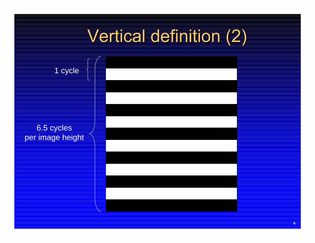
1 cycle
6.5 cyclesper image height

7
1 cycle
1.5 cyclesper image height

8
1 cycle
33.5 cyclesper image width

9
1 cycle6.5 cycles
per image width

10
1 cycle
1.5 cyclesper image width

11
+ =
13579
111315
2468
101214
Odd field Even field Complete image
1/60s 1/60s 1/30s
13
5
A
B
A
D
C
B
246
D
C
Odd lines Odd field flyback Even lines Even field flyback
Number of lines: 525Number of images: 30
Number of fields: 602 fields = 1 image

12
Horizontal scanning Horizontal flyback Vertical flyback
..1
3
5
7
9
11
13
15
17
19
2
4
6
8
10
12
14
16
18
C
D B.
A
.

13
100
75
50
25
0
Am
plitu
de %
White level
Blanking level
Maximum level
Video signal
Horizontal synchronism
Line N

14
even
odd

15
fh: Line frequency (15.750)
fv: Field frequency (60)
fv 2fhfh2fv
0f
f0 5 MHz

16
Microphone
TV camera
Audio Amplif.
FMmodulator
Sound carrier
RF Amplif.
Video Amplif.
Sync.generation
camaratime
base
Video adder
+ sync
AMmodulator
Video carrier
Video R.F.
Amplif.
VestigialLateral band
filter
+

17
0 1
1
0.5
0.5
Receive
r
Emitter
X
Y
Y=X1/2.8
Y=X2.8

18
Tuner FIAmplifier
Detector
GACDelayGAC
VideoAmplif.
Sounddetector
Sound Amplif.
Syncseparator
Sync. processing
Sync processing
Line oscilator
Fieldoscilator
LineoutputFieldoutput
Limiter Amplif.
19
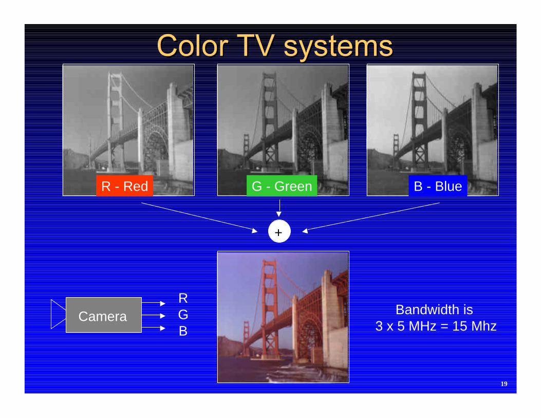
+
RGB
Camera Bandwidth is 3 x 5 MHz = 15 Mhz
B - BlueG - GreenR - Red

20
CameraRGB
Bandwidth is 7 Mhz
Y - Luminance
Y = 0.30R + 0.59G + 0.11Bu = 0.495 (B – Y)v = 0.877 (R - Y)
5 MHz1 MHz1 Mhz
u = 0.495 (B – Y) v = 0.877 (R - Y)

21
Y + R - Y = RY + G - Y = GY + B - Y = B
CameraRGB
Bandwidth is 7 Mhz
Y = 0.30R + 0.59G + 0.11BR - YB - Y
5 MHz1 MHz1 Mhz
R-Y = R - (0.30R + 0.59G + 0.11B) = 0.7R - 0.59G - 0.11B
B-Y = B - (0.30R + 0.59G + 0.11B) = -0.3R - 0.59G + 0.89B
ReceiverY
R - YB - Y
G - Y = -(0.3/0.59)(R - Y) - (0.11/0.59)(B - Y)
Screen

22
1.0 1.01.0 1.0 1.0
1.01.01.01.0
1.0 1.0 1.01.0
1.0
0.20
0.20
0.20
0.20
0 0
0 0
0 0 0
0 0
0 0
0 0
0 0
0 0
0.5
0.5
0.5
0.30 0.15 0.65 0.59 0.11 0.70 0.41 0.89
0.700.35 0.35
-0.59-0.11
-0.70-0.59
0.11
-0.30 -0.15 -0.15
0.41
-0.11
0.30
-0.41
0.11
-0.30 -0.15 -0.15 -0.59
0.89 0.30 0.59
-0.89
Whi
te
Gra
y Sat
urat
ed re
d (v
ery
brig
ht)
Sat
urat
ed r
ed(le
ss b
right
)
Des
atur
ated
red
Sat
urat
ed g
reen
Sat
urat
ed b
lue
Sat
urat
ed c
yan
Sat
urat
ed m
agen
ta
Sat
urat
ed y
ello
w
R
G
B
Y
R-Y
G-Y
B-Y

23
NTSC defines
I = 0.877 (R – Y) cos 33 – 0.493 (B – Y) sin 33
Q = 0.877 (R – Y) sin 33 + 0.493 (B – Y) cos 33
I Bandwidth: 1.5 Mhz
Q Bandwidth: 0.5 Mhz
Note: Next slides will use, (I,Q), (u,v) or (R-Y, B-Y) indistinctlySignals are not exactly the same, but concepts are.
There is a weighting factor applied

24
0.1 0.2 0.3 0.4 0.5 0.6 0.7
-0.1-0.2-0.3-0.4-0.5-0.6-0.7
0.1
0.2
0.3
0.4
0.5
0.6
0.7
-0.1
-0.2
-0.3
-0.4
-0.5
-0.6
-0.7
Magenta 61°
Blue 347°
Cyan 283°
Green241°
Yellow167°
Red103°
U 0.493 (B-Y)
V 0.877 (R-Y)
Hue
saturation

25
+90
Amplitudemodulation
subcarrieroscilator
+CHROMINANCE
I
Q
S(t) = I cos(ωst+33) + Q sin(ωst+33)
S(t)
Amplitudemodulator
3.58 Mhz

26
1.00.89
0.700.59
0.410.30
0.11
0.0
Whi
te
Cya
n
Gre
en
Mag
enta
Red
Blu
e
Bla
ck
Burst 10 ± 1 cycles
0.90
0.90
0.76
0.76
0.83
0.83
0.83
0.83
0.76
0.76
0.90
0.90
Luminance signal
Chrominance signal
Yel
low

27
0.90
0.90
0.76
0.76
0.83
0.83
0.90
0.90
0.83
0.83
0.76
0.76
0
1.0
0.2
0.4
0.6
0.8
1.2
1.4
-0.2
-0.4-0.33
1.33
100 %
75%
20 %
0
Car
rier
am
plitu
de

28
0.44
0.44
0.63
0.63
0.59
0.590.44
0.44
0.59
0.59
0.63
0.63
0
1.0
0.20.40.60.8
1.21.4
-0.2-0.4-0.33
1.33
100 %
75 %
20 %
0
Car
rier
am
plitu
de Black level
Yel
low
Whi
te
Cya
n
Cya
n
Mag
enta
Red
Blu
e
Bla
ck
White level

29
f (MHz)0 1 2 3 4 5
f (MHz)0 1 2 3 4 5
f (MHz)0 1 2 3 4 5
f (MHz)0 1 2 3 4 5
4. 43 (color subcarrier - PAL)3.58 (color subcarrier – NTSC)
u
v
Composite signal
Y
Bandwidth depends on (I,Q) or (u,v) signals
Bandwidth depends on (I,Q) or (u,v) signals

30
0.493 (B-Y)
0.877 (R-Y)
0.493 (B-Y)
-0.877 (R-Y)
Line n
Line n+1
φ
- φ
S(t) = (B-Y)sin(ωst) + (R-Y)cos(ωst)-
R – Y is switched each line to compensate for thephase errors (hue)

31
B-Y
R-Y
E n
E n+1
EMITTER
B-Y
R-Y
En
E n+1
Cn+1
C n
RECEIVER
ϕ
n+1C '
ϕ

32
l Component sampling
Applications: multimedia, Digital TV
l Composite signal sampling
Applications at the TV receiver
Image enhancement
Flicker reduction

33
ITU - 601 CIF QCIF
Sampled signals Y, u, v Y, u, v Y, u, v
Sampling frequency Mhz. (Y) 13.5 - (u,v) 6.75 (Y) 6.75 - (u,v) 3.375 (Y) 6.75 - (u,v) 3.375
Sampling structure orthogonal 1:1 orthogonal 1:1 orthogonal 1:1
Pixels / image (Y): 720 x 576 (Y): 352 x 288 (Y): 176 x 144 (u,v): 360 x 288 (u,v): 176 x 144 (u,v): 88 x 72
Bits/pixel 8 8 8