l-pro 4000 manual - erlphaseerlphase.com/downloads/manuals/l_pro_4000_manual.pdf · 79...
TRANSCRIPT
L-PRO 4000Transmission Line Protection Relay
User ManualVersion 2.5 Rev 1


D02706R02.50 L-PRO 4000 User Manual i
Preface
Information in this document is subject to change without notice.© 2015 ERLPhase Power Technologies Ltd. All rights reserved.Reproduction in any manner whatsoever without the written permission of ERLPhase Power Technologies Ltd. is strictly forbidden.This manual is part of a complete set of product documentation that includes detailed drawings and operation. Users should evaluate the information in the context of the complete set of product documentation and their particular applications. ERLPhase assumes no liability for any incidental, indirect or consequential damages arising from the use of this documentation.While all information presented is believed to be reliable and in accordance with accepted engineering practices, ERLPhase makes no warranties as to the completeness of the information.All trademarks used in association with B-PRO, B-PRO Multi Busbar, Multi Busbar Protection, F-PRO, iTMU, L-PRO, ProLogic, S-PRO, T-PRO, TESLA, I/O Expansion Module, TESLA Control Panel, Relay Control Panel, RecordGraph and RecordBase are trademarks of ERLPhase Power Technologies Ltd.
Windows® is a registered trademark of the Microsoft Corporation.HyperTerminal® is a registered trademark of Hilgraeve.Modbus® is a registered trademark of Modicon.
Contact Information
ERLPhase Power Technologies Ltd.Website: www.erlphase.comEmail: [email protected]
Technical SupportEmail: [email protected]: 1-204-477-0591

D02706R02.51 L-PRO 4000 User Manual iii
Using This Guide
This User Manual describes the installation and operation of the L-PRO line protection relay. It is intended to support the first time user and clarify the de-tails of the equipment.
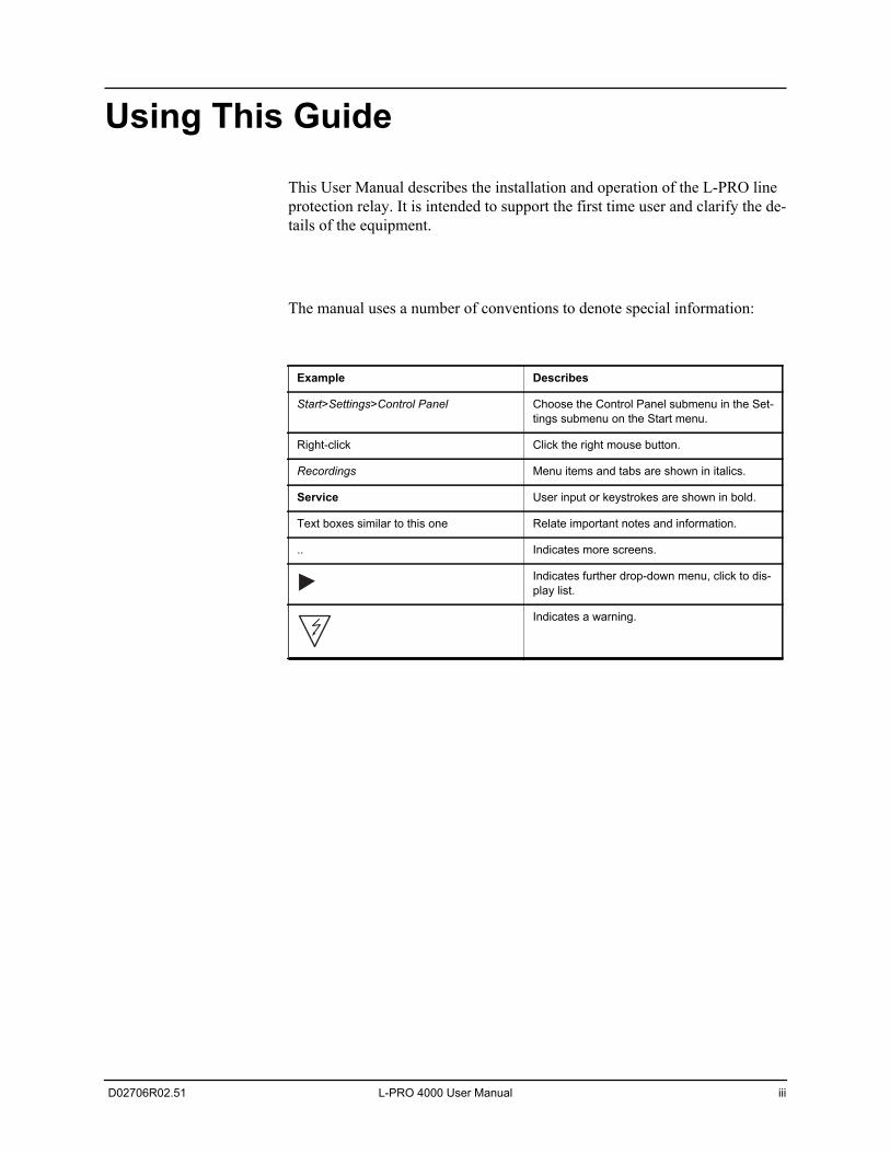
The manual uses a number of conventions to denote special information:
Example Describes
Start>Settings>Control Panel Choose the Control Panel submenu in the Set-tings submenu on the Start menu.
Right-click Click the right mouse button.
Recordings Menu items and tabs are shown in italics.
Service User input or keystrokes are shown in bold.
Text boxes similar to this one Relate important notes and information.
.. Indicates more screens.
Indicates further drop-down menu, click to dis-play list.
Indicates a warning.

D02706R02.51 L-PRO 4000 User Manual v
Table of Contents
Preface ......................................................................................iContact Information ...................................................................iUsing This Guide ..................................................................... iiiTable of Contents .....................................................................vAcronyms.................................................................................ixVersion Compatibility ...............................................................xiPC System Requirements and Software Installation ............. xiii
1 Overview ................................................................. 1-1Introduction ...................................................................... 1-1Front View........................................................................ 1-3Rear View ........................................................................ 1-4Model Options/Ordering................................................... 1-6
2 Setup and Communications.................................. 2-1Introduction ...................................................................... 2-1Power Supply................................................................... 2-1Time Sources................................................................... 2-2Communicating with the Relay Intelligent Electronic Device (IED)................................................................................. 2-2USB Link .......................................................................... 2-3Network Link .................................................................... 2-5Direct Serial Link.............................................................. 2-6Modem Link ..................................................................... 2-7Using HyperTerminal to Access the Relay’s Maintenance Menu ................................................................................ 2-9Firmware Update ........................................................... 2-12Setting the Baud Rate.................................................... 2-13Accessing the Relay’s SCADA Services........................ 2-14Communication Port Details .......................................... 2-15
3 Using the IED (Getting Started) ............................ 3-1Introduction ...................................................................... 3-1Start-up Sequence ........................................................... 3-1Interfacing with the Relay................................................. 3-1Front Panel Display.......................................................... 3-2Terminal Mode ................................................................. 3-8Relay Control Panel ......................................................... 3-8
4 Protection Functions and Specifications ............ 4-1
Table of Contents
vi L-PRO 4000 User Manual D02706R02.51
Protection and Recording Functions................................ 4-1Communication-Aided Scheme ..................................... 4-50Recording Functions ...................................................... 4-56Event Log....................................................................... 4-59Fault Log ........................................................................ 4-60
5 Data Communications ........................................... 5-1Introduction ...................................................................... 5-1SCADA Protocol .............................................................. 5-1IEC 61850 Communication .............................................. 5-7
6 Offliner Settings Software ..................................... 6-1Introduction ...................................................................... 6-1Offliner Features .............................................................. 6-2Offliner Keyboard Shortcuts............................................. 6-5Handling Backward Compatibility .................................... 6-6RecordBase View Software ............................................. 6-8Main Branches from the Tree View.................................. 6-9Settings From a Record ................................................. 6-30
7 Acceptance/Protection Function Test Guide ...... 7-1Introduction ...................................................................... 7-1Acceptance Testing ......................................................... 7-1L-PRO Acceptance Test Procedure Outline .................... 7-4
8 Installation .............................................................. 8-1Introduction ...................................................................... 8-1Physical Mounting............................................................ 8-1AC and DC Wiring............................................................ 8-1Communication Wiring..................................................... 8-1
Appendix A IED Specifications..................................... A-1Distance Element Operating Time Curves at Nominal Frequency ........................................................................A-8Frequency Element Operating Time Curves..................A-10External Input Pickup Filter ............................................A-12
Appendix B IED Settings and Ranges .........................B-1Settings and Ranges........................................................B-1
Appendix C Hardware Description ...............................C-1
Appendix D Event Messages .......................................D-1
Appendix E Modbus RTU Communication Protocol ....E-1
Appendix F DNP3 Device Profile ................................. F-1
Appendix G Mechanical Drawings ...............................G-1
Table of Contents
D02706R02.51 L-PRO 4000 User Manual vii
Appendix H Rear Panel Drawings................................H-1
Appendix I AC Schematic Drawings ............................. I-1
Appendix J DC Schematic Drawings ............................J-1
Appendix K Function Logic Diagram............................K-1
Appendix L L-PRO Setting Example ............................ L-1Switching Setting Groups................................................. L-279 Auto-recloser Examples.............................................. L-9
Appendix M Failure Modes ......................................... M-1Actions ............................................................................ M-1
Appendix N IEC61850 Implementation ........................N-1Protocol Implementation Conformance Statement (PICS) ..............................................................................N-1Model Implementation Conformance Statement (MICS)..............................................................................N-8Data Mapping Specifications .........................................N-56
Index ........................................................................................ 1

D02706R02.51 L-PRO 4000 User Manual ix
Acronyms
ASG - Active Setting Group
CCVT - Capacitance Coupled Voltage Transformer
CID - file extension (.CID) for Configured IED Description
CS - Control Switch
CT - Current Transformer
DCB - Directional Comparison Blocking
DCE - Data Communication Equipment
DIB - Digital Input Board
DIGIO - Digital Input/Output Board
DMDA - Dead Main Dead Aux
DMLA - Dead Main Live Aux
DSP - Digital signal processor
DTE - Data Terminal Equipment
GFPCB - Graphics Front Panel Comm Board
GFPDB - Graphics Front Panel Display Board
GPS - Global Positioning System
HMI - Human Machine Interface
ICD - file extension (.ICD) for IED Capability Description
IEC - International Electrotechnical Commission
IED - Intelligent Electronic Device
IP - Internet Protocol (IP) address
IRIG-B - Inter-range instrumentation group time codes
LE- Load Encroachment
LED - Light-emitting Diode
LHS - Left Hand Side
LMDA - Live Main Dead Aux
Acronyms
x L-PRO 4000 User Manual D02706R02.51
LOCB - L-PRO Output Contact Board
LOCBH - L-PRO Output Contact Board - HCFI
LOP - Loss of Potential
MPB - Main Processor Board
MPC - Micro Processor
PLC - Programmable Logic Controller
POTT - Permissive Over-reaching Transfer Trip
PUTT - Permissive Under-reaching Transfer Trip
PT - Permissive Trip
RAIB -Relay AC Analog Input Board
RASB -Relay AC Analog Sensor Boards
RHS - Right Hand Side
RPCB - Rear Panel Comm Board
RTOS - Real Time Operating System
RTU - Remote Terminal Unit
SCADA - Supervisory Control And Data Acquisition
SG - Setting Group
SIR ratio - Source Impedance Ratio
SOTF - Switch-On-To-Fault
TT - Transfer Trip
TUI - Terminal User Interface
UI - User Interface
VI - Virtual Input
WI - Weak Infeed
D02706R02.51 L-PRO 4000 User Manual xi
Version Compatibility
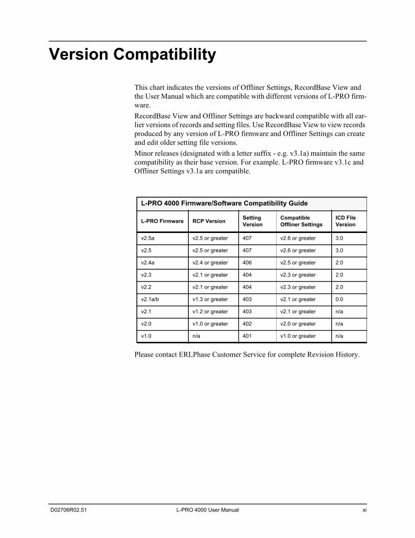
This chart indicates the versions of Offliner Settings, RecordBase View and the User Manual which are compatible with different versions of L-PRO firm-ware.RecordBase View and Offliner Settings are backward compatible with all ear-lier versions of records and setting files. Use RecordBase View to view records produced by any version of L-PRO firmware and Offliner Settings can create and edit older setting file versions.Minor releases (designated with a letter suffix - e.g. v3.1a) maintain the same compatibility as their base version. For example. L-PRO firmware v3.1c and Offliner Settings v3.1a are compatible.
Please contact ERLPhase Customer Service for complete Revision History.
L-PRO 4000 Firmware/Software Compatibility Guide
L-PRO Firmware RCP Version Setting Version
Compatible Offliner Settings
ICD File Version
v2.5a v2.5 or greater 407 v2.6 or greater 3.0
v2.5 v2.5 or greater 407 v2.6 or greater 3.0
v2.4a v2.4 or greater 406 v2.5 or greater 2.0
v2.3 v2.1 or greater 404 v2.3 or greater 2.0
v2.2 v2.1 or greater 404 v2.3 or greater 2.0
v2.1a/b v1.3 or greater 403 v2.1 or greater 0.0
v2.1 v1.2 or greater 403 v2.1 or greater n/a
v2.0 v1.0 or greater 402 v2.0 or greater n/a
v1.0 n/a 401 v1.0 or greater n/a

D02706R02.51 L-PRO 4000 User Manual xiii
PC System Requirements and Software Installation
HardwareThe minimum hardware requirements are: • 1 GHz processor
• 2 GB RAM
• 20 GB available hard disk space
• USB port
• Serial communication port
Operating SystemThe following software must be installed and functional prior to installing the applications:
• Microsoft Windows XP Professional Service Pack 3 or
• Microsoft Windows 7 Professional Service Pack 1
Relay Control Panel requires Windows XP SP3 (it will not work on earlier ver-sions of Windows).
Software InstallationThe CD-ROM contains software and the User Manual for the L-PRO Trans-mission Line Protection Relay.
Software is installed directly from the CD-ROM to a Windows PC. Alterna-tively, create installation diskettes to install software on computers without a CD-ROM drive.
The CD-ROM contains the following:
• L-PRO Offliner Settings: Offliner settings program for the relay
• L-PRO Firmware: Firmware and installation instructions
• L-PRO User Manual: L-PRO manual in PDF format
• L-PRO Function Logic Diagram: diagram in PDF format
• Relay Control Panel: software
• Relay Control Panel User Manual: manual in PDF format
• USB Driver
To Install Software on the ComputerInsert the CD-ROM in the drive. The CD-ROM should open automatically. If the CD-ROM does not open automatically, go to Windows Explorer and find the CD-ROM (usually on D drive). Open the ERLPhase.exe file to launch the CD-ROM.
PC System Requirements and Software Installation
xiv L-PRO 4000 User Manual D02706R02.51
To install the software on the computer, click the desired item on the screen. The installation program launches automatically. Installation may take a few minutes to start.
To view the L-PRO User Manual the user must have Adobe Acrobat on the computer. If a copy is needed, download a copy at www.adobe.com.
Anti-virus/Anti-spyware SoftwareIf an anti-virus/anti-spyware software on your local system identifies any of the ERLPhase applications as a “potential threat”, it will be necessary to con-figure your anti-virus/anti-software to classify it as “safe” for its proper oper-ation. Please consult the appropriate anti-virus/anti-spyware software documentation to determine the relevant procedure.
D02706R02.51 L-PRO 4000 User Manual 1-1
1 Overview
1.1 IntroductionThe L-PRO 4000 provides easy-to-use, state-of-the-art comprehensive dis-tance and directional line protection for medium to extra high voltage transmis-sion lines using communication-based schemes. It provides control, automation, metering, monitoring, fault oscillography, dynamic swing record-ing, event logging with advanced communications in a flexible cost effective package.
The primary protection is line protection with 5 zones of phase and ground dis-tance functions – user-defined Mho or Quadrilateral shapes and communica-tions based schemes (i.e. teleprotection or pilot schemes).
To provide a complete package of protection and control the relay supplies oth-er functions such as:
• 1.0 to 1.3 cycle operation at 80% reach, ideal for EHV transmission line applications
• Ring bus capability – breaker failure and individual breaker monitoring
• 4-shot recloser with dead line/dead bus control and sync check
• Single pole and three pole trip and reclose
• 24 statements of ProLogic addresses special protection needs
• Power Swing Blocking / Tripping
• Load Encroachment
• Switch-On-To-Fault function
• VT Supervision function
• CT Supervision function
• Over / Under Voltage functions
• 8 Setting Groups (SG) with setting group logic
• Back up Directional overcurrent and earth fault protection
• Over / Under / Rate of change of frequency devices
Relay Control Panel (RCP) is the Windows graphical user interface software tool provided with all 4000 series and higher (new generation) ERL relays to communicate, retrieve and manage records, event logs, fault logs, manage set-tings (identification, protection, SCADA etc.,), display real time metering val-ues, view, analyze, and export records in COMTRADE format.
In addition to the protection functions the relay provides fault recording (96 samples/cycle) to analyze faults and to review the operation of the overall pro-tection scheme. The relay also has low speed swing recording which can be used to analyze system stability. The triggers for fault recording are established
1 Overview
1-2 L-PRO 4000 User Manual D02706R02.51
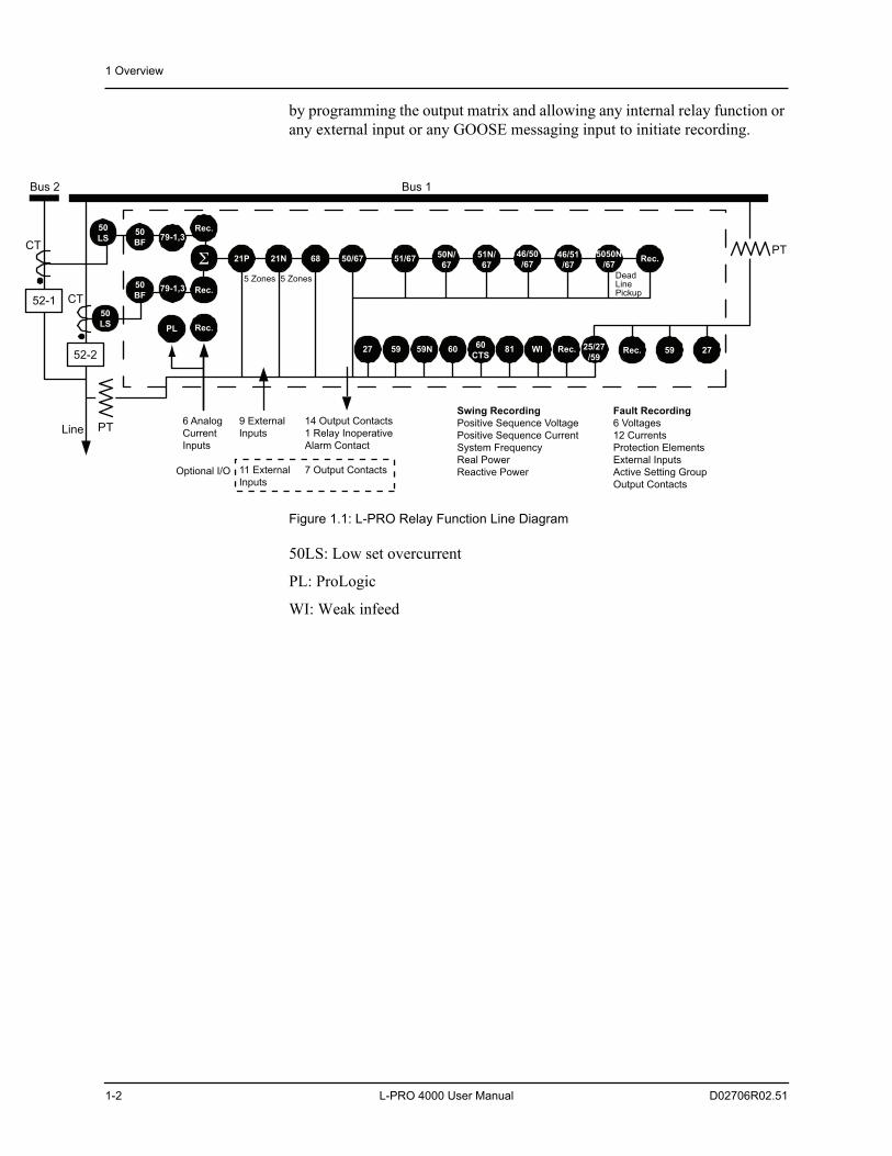
by programming the output matrix and allowing any internal relay function or any external input or any GOOSE messaging input to initiate recording.
Figure 1.1: L-PRO Relay Function Line Diagram
50LS: Low set overcurrent
PL: ProLogic
WI: Weak infeed
5050N
/67
27 59 60 WI Rec. 25/27
/59
21P 21N 68 50/67 51/6750N/
67
51N/
67
46/50
/67Rec.
46/51
/67
Bus 1
52-2
PT
PT
CT
Line
5 Zones 5 Zones DeadLinePickup
Fault Recording
6 Voltages
12 Currents
Protection Elements
External Inputs
Active Setting Group
Output Contacts
Swing Recording
Positive Sequence Voltage
Positive Sequence Current
System Frequency
Real Power
Reactive Power
6 Analog
Current
Inputs
14 Output Contacts
1 Relay Inoperative
Alarm Contact
7 Output Contacts
59 27
52-1
50
BF
50
BF
Σ
CT
Rec.
Rec.
Bus 2
9 External
Inputs
11 External
Inputs
Rec.
Rec.
79-1,3
79-1,3
81
50
LS
50
LSPL
Optional I/O
59N60
CTS
1 Overview
D02706R02.51 L-PRO 4000 User Manual 1-3
1.2 Front View
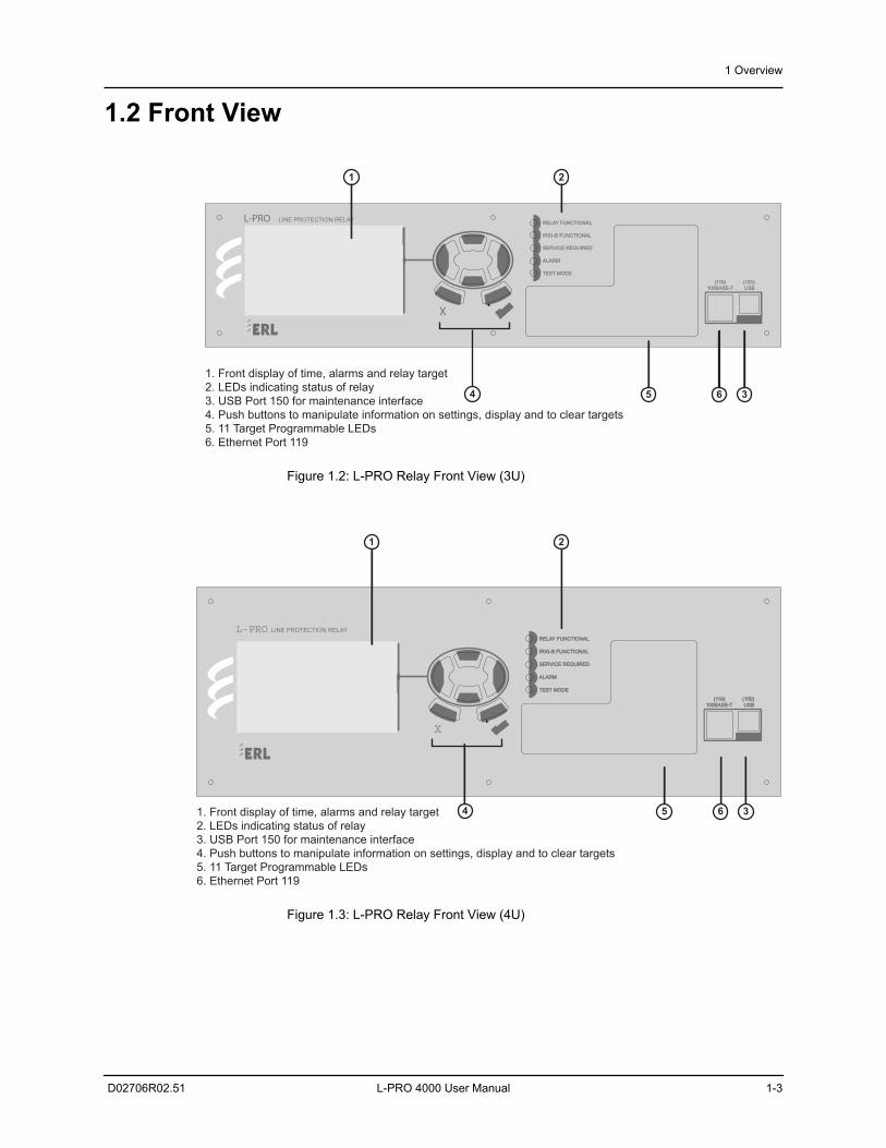
Figure 1.2: L-PRO Relay Front View (3U)
Figure 1.3: L-PRO Relay Front View (4U)
RELAY FUNCTIONAL
IRIG-B FUNCTIONAL
SERVICE REQUIRED
TEST MODE
ALARM
LINE PROTECTION RELAYL-PRO
X
100BASE-T
(119) (150)
USB
1 2
34 5 6
1. Front display of time, alarms and relay target
2. LEDs indicating status of relay
3. USB Port 150 for maintenance interface
4. Push buttons to manipulate information on settings, display and to clear targets
5. 11 Target Programmable LEDs
6. Ethernet Port 119
RELAY FUNCTIONAL
IRIG-B FUNCTIONAL
SERVICE REQUIRED
TEST MODE
ALARM
LINE PROTECTION RELAYL-PRO
X
100BASE-T(119) (150)
USB
1 2
34 5 61. Front display of time, alarms and relay target2. LEDs indicating status of relay3. USB Port 150 for maintenance interface4. Push buttons to manipulate information on settings, display and to clear targets5. 11 Target Programmable LEDs6. Ethernet Port 119
1 Overview
1-4 L-PRO 4000 User Manual D02706R02.51
1.3 Rear View
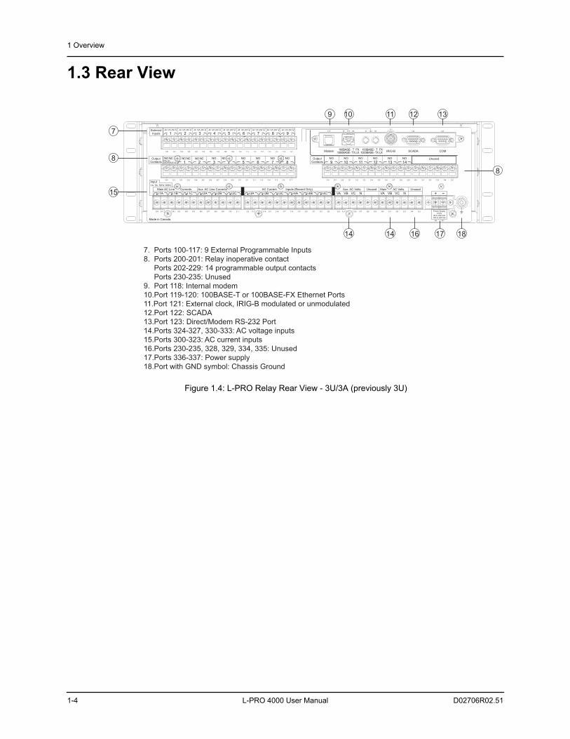
Figure 1.4: L-PRO Relay Rear View - 3U/3A (previously 3U)
Power Supply±10%
48 to 250 Vdc100 to 240 Vac
I1A I2A I3A I4AI1B I2B I3B I4BI1C I2C I3C I4C
Input1A 50Hz5A 60Hz
Main AC Line Currents
Made in Canada
AC Current Inputs (Record Only)Aux. AC Line Currents
300 312 324301 313 325302 314 326303 315 327304 316 328305 317 329306 318 330307 319 331308 320 332309 321 333310 322 334
336
311 323 335
337
VA VAVB VBVC VCN N
Aux. AC Volts Main AC VoltsUnused Unused
Unused
200 218201 219202 220203 221204 222205 223206 224207 225208 226209 227210 228211 229212 230213 231214 232215 233216 234217 235
RELAYINOPERATIVE
NCNONCNO NCNO NO NONO NO NO NO NO NO NO NO NO NOOutputContacts
OutputContacts6 7 81 2 3 9 10 11 12 13 144 5
1 2 3 4 5 6 7 8 9ExternalInputs
100 101 102 103 104 105 106 107 108 109 110 111 112 113 114 115 116 117
48 125 250 V 48 125 250 V 48 125 250 V 48 125 250 V 48 125 250 V 48 125 250 V 48 125 250 V 48 125 250 V 48 125 250 V
Modem IRIG-B SCADA COM100BASE-
1000BASE-FXTLXTX
100BASE-1000BASE-
FXTLXTX
RXRX TXTX118 119 120121
122 123
7. Ports 100-117: 9 External Programmable Inputs
8. Ports 200-201: Relay inoperative contact
Ports 202-229: 14 programmable output contacts
Ports 230-235: Unused
9. Port 118: Internal modem
10.Port 119-120: 100BASE-T or 100BASE-FX Ethernet Ports
11.Port 121: External clock, IRIG-B modulated or unmodulated
12.Port 122: SCADA
13.Port 123: Direct/Modem RS-232 Port
14.Ports 324-327, 330-333: AC voltage inputs
15.Ports 300-323: AC current inputs
16.Ports 230-235, 328, 329, 334, 335: Unused
17.Ports 336-337: Power supply
18.Port with GND symbol: Chassis Ground
9 1310 11 12
14 171614 18
8
15
7
8
1 Overview
D02706R02.51 L-PRO 4000 User Manual 1-5
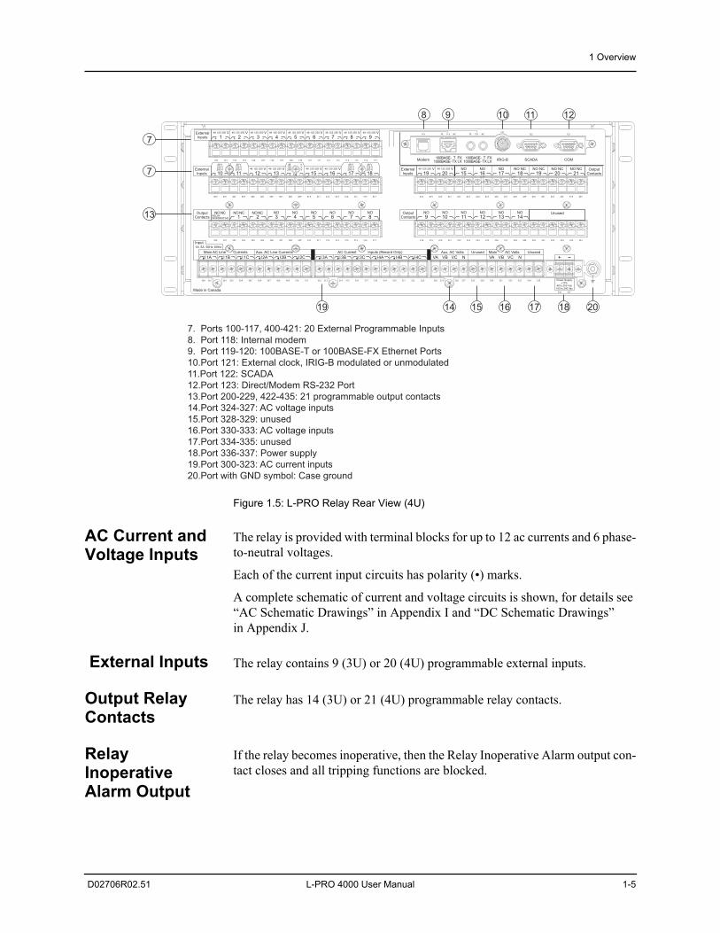
Figure 1.5: L-PRO Relay Rear View (4U)
AC Current and Voltage Inputs
The relay is provided with terminal blocks for up to 12 ac currents and 6 phase-to-neutral voltages.
Each of the current input circuits has polarity (•) marks.
A complete schematic of current and voltage circuits is shown, for details see “AC Schematic Drawings” in Appendix I and “DC Schematic Drawings” in Appendix J.
External Inputs The relay contains 9 (3U) or 20 (4U) programmable external inputs.
Output Relay Contacts
The relay has 14 (3U) or 21 (4U) programmable relay contacts.
Relay Inoperative Alarm Output
If the relay becomes inoperative, then the Relay Inoperative Alarm output con-tact closes and all tripping functions are blocked.
Power Supply±10%
48 to 250 Vdc100 to 240 Vac
I1A I2A I3A I4AI1B I2B I3B I4BI1C I2C I3C I4C
Input1A 50Hz5A 60Hz
Main AC Line Currents AC Current Inputs (Record Only)Aux. AC Line Currents
300 312 324301 313 325302 314 326303 315 327304 316 328305 317 329306 318 330307 319 331308 320 332309 321 333310 322 334
336
311 323 335
337
VA VAVB VBVC VCN N
Aux. AC Volts Main AC VoltsUnused Unused
Made in Canada
Unused
200 218201 219202 220203 221204 222205 223206 224207 225208 226209 227210 228211 229212 230213 231214 232215 233216 234217 235
RELAYINOPERATIVE
NCNONCNONCNO NO NO NO NO NO NO NO NO NO NO NO NOOutputContacts
OutputContacts6 7 81 2 3 4 9 10 11 12 13 145
19 2010 11 12 13 14 15 16 17 18NONO NO NO NC NO NC NO NC NO NC Output
Contacts1615 17 18 19 20 21ExternalInputs
ExternalInputs
400 418401 419402 420403 421404 422405 423406 424407 425408 426409 427410 428411 429412 430413 431414 432415 433416 434417 435
48 125 250 V 48 125 250 V48 125 250 V 48 125 250 V 48 125 250 V 48 125 250 V
48 V125 V250 V
48 V125 V250 V
48 V125 V250 V
48 V125 V250 V
48 VV125V250
1 2 3 4 5 6 7 8 9ExternalInputs
100 101 102 103 104 105 106 107 108 109 110 111 112 113 114 115 116 117
48 125 250 V 48 125 250 V 48 125 250 V 48 125 250 V 48 125 250 V 48 125 250 V 48 125 250 V 48 125 250 V 48 125 250 V
Modem IRIG-B SCADA COM100BASE-
1000BASE-FXTLXTX
100BASE-1000BASE-
FXTLXTX
RXRX TXTX118 119 120121
122 123
7. Ports 100-117, 400-421: 20 External Programmable Inputs
8. Port 118: Internal modem
9. Port 119-120: 100BASE-T or 100BASE-FX Ethernet Ports
10.Port 121: External clock, IRIG-B modulated or unmodulated
11.Port 122: SCADA
12.Port 123: Direct/Modem RS-232 Port
13.Port 200-229, 422-435: 21 programmable output contacts
14.Port 324-327: AC voltage inputs
15.Port 328-329: unused
16.Port 330-333: AC voltage inputs
17.Port 334-335: unused
18.Port 336-337: Power supply
19.Port 300-323: AC current inputs
20.Port with GND symbol: Case ground
8 129 10 11
1817 2019
7
13
7
14 15 16
1 Overview
1-6 L-PRO 4000 User Manual D02706R02.51
1.4 Model Options/OrderingThe relay is available as a horizontal mount, for details see “Mechanical Draw-ings” in Appendix G.
The relay is available with an optional internal modem card.
The two rear Ethernet ports can be ordered as one copper-one optical port or both optical ports or both copper ports. These ports on the rear panel are avail-able as either 100BASE-T (RJ-45) or 100BASE-FX (optical ST).
The Current Transformer (CT) inputs are 1 A nominal or 5 A nominal.
The external inputs are 48, 110/125 or 220/250 Vdc.
The system base frequency is either 50 Hz or 60 Hz.
The L-PRO 4000 is available in a standard 3U/3A (previously 3U) rack model or as 4U/4A (previously 4U) model with an optional I/O board as described above.
All of the above options must be specified at the time of ordering.
D02706R02.51 L-PRO 4000 User Manual 2-1
2 Setup and Communications
2.1 IntroductionThis chapter discusses setting up and communicating with the relay including the following:
• Power supply
• Inter-Range Instrumentation Group time codes (IRIG-B) time input
• Communicating with the relay using a network link, a direct serial link and a modem link (internal, external)
• Using Relay C
• ontrol Panel to access the relay’s user interface
• Using HyperTerminal to access the relay’s maintenance menu
• Setting the Baud rate
• Accessing the relay’s Supervisory Control And Data Acquisition (SCADA) services
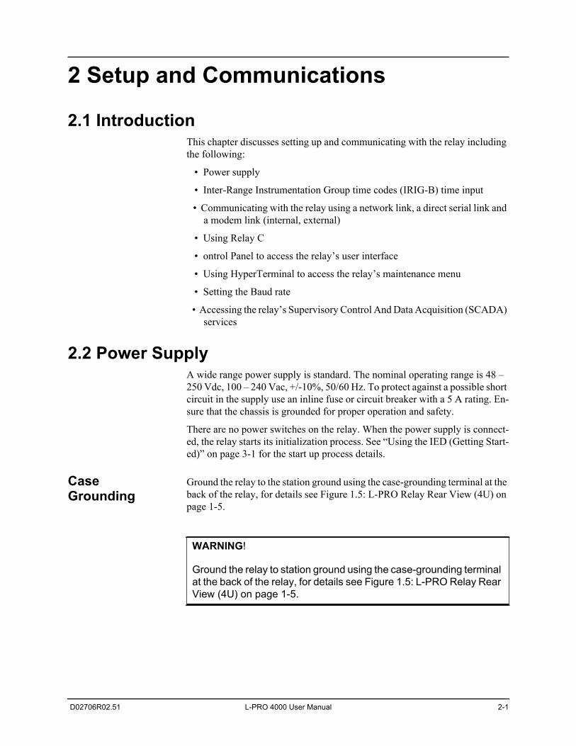
2.2 Power SupplyA wide range power supply is standard. The nominal operating range is 48 – 250 Vdc, 100 – 240 Vac, +/-10%, 50/60 Hz. To protect against a possible short circuit in the supply use an inline fuse or circuit breaker with a 5 A rating. En-sure that the chassis is grounded for proper operation and safety.
There are no power switches on the relay. When the power supply is connect-ed, the relay starts its initialization process. See “Using the IED (Getting Start-ed)” on page 3-1 for the start up process details.
Case Grounding
Ground the relay to the station ground using the case-grounding terminal at the back of the relay, for details see Figure 1.5: L-PRO Relay Rear View (4U) on page 1-5.
WARNING!
Ground the relay to station ground using the case-grounding terminal at the back of the relay, for details see Figure 1.5: L-PRO Relay Rear View (4U) on page 1-5.
2 Setup and Communications
2-2 L-PRO 4000 User Manual D02706R02.51
2.3 Time SourcesThe L-PRO 4000 Line Protection relay supports the use of modulated or un-modulated IRIG-B time signals (external), primary/secondary SNTP network based time synchronization (external) and manually configurable system time based on a free-running, internal oscillator. The internal free-running oscillator is always present on the IED and, in the absence of any external time source, will become the default mode of time synchronization.
An externally applied IRIG-B time source will have the highest order of pre-cedence, and will typically offer the highest available time accuracy, exceed-ing 1 μs after calibration, when derived from an external GPS satellite source. The L-PRO 4000 Line Protection relay will also process derived IRIG-B style signals generated from alternate time sources, using time quality information to differentiate. The ongoing presence of a valid IRIG-B time source is indicat-ed by an LED on the front panel of the IED and is evident in data records.
An SNTP time source has a lower order of precedence from a valid IRIG-B source. SNTP operation (primary and secondary) requires network access and the selection and configuration of suitable SNTP network sources. The SNTP time may be configured for re-synchronization cycles ranging from 15 minutes to 36 hours, adjusting the IED system time to an accuracy within +/- 1 second. No visual indication is provided on the IED front panel regarding the status of the SNTP synchronization however this information is available in data re-cords.
The IED comes equipped with an internal free-running oscillator used to gen-erate a 1 PPS time signal in the absence of any alternate available time source. Use of this oscillator as the primary IED time source requires manual time con-figuration, with the general accuracy subject to user input parameters, and is recommended primarily for stand-alone, unsynchronized applications. The in-ternal oscillator carries a lifetime accuracy (including temperature effects and aging) of +/-25 ppm.
2.4 Communicating with the Relay Intelligent Electronic Device (IED)
Connect to the relay to access its user interface and supervisory control and data acquisition (SCADA) services by:
• Front USB 2.0 interface (maintenance)
• 1 front and 2 rear Ethernet network links (user interface and SCADA)
• Direct serial link (user interface and SCADA)
• External or internal modem link (user interface only)
The relay has a front panel USB( Port 150) and 1 front Port 119 and 1 rear panel Ethernet port 119 and 1 rear panel Ethernet Port 120 and 2 rear serial Ports 122 and 123) to provide direct access to its user interface and SCADA services.
The relay’s user interface is accessed through the Relay Control Panel.
2 Setup and Communications
D02706R02.51 L-PRO 4000 User Manual 2-3
2.5 USB Link
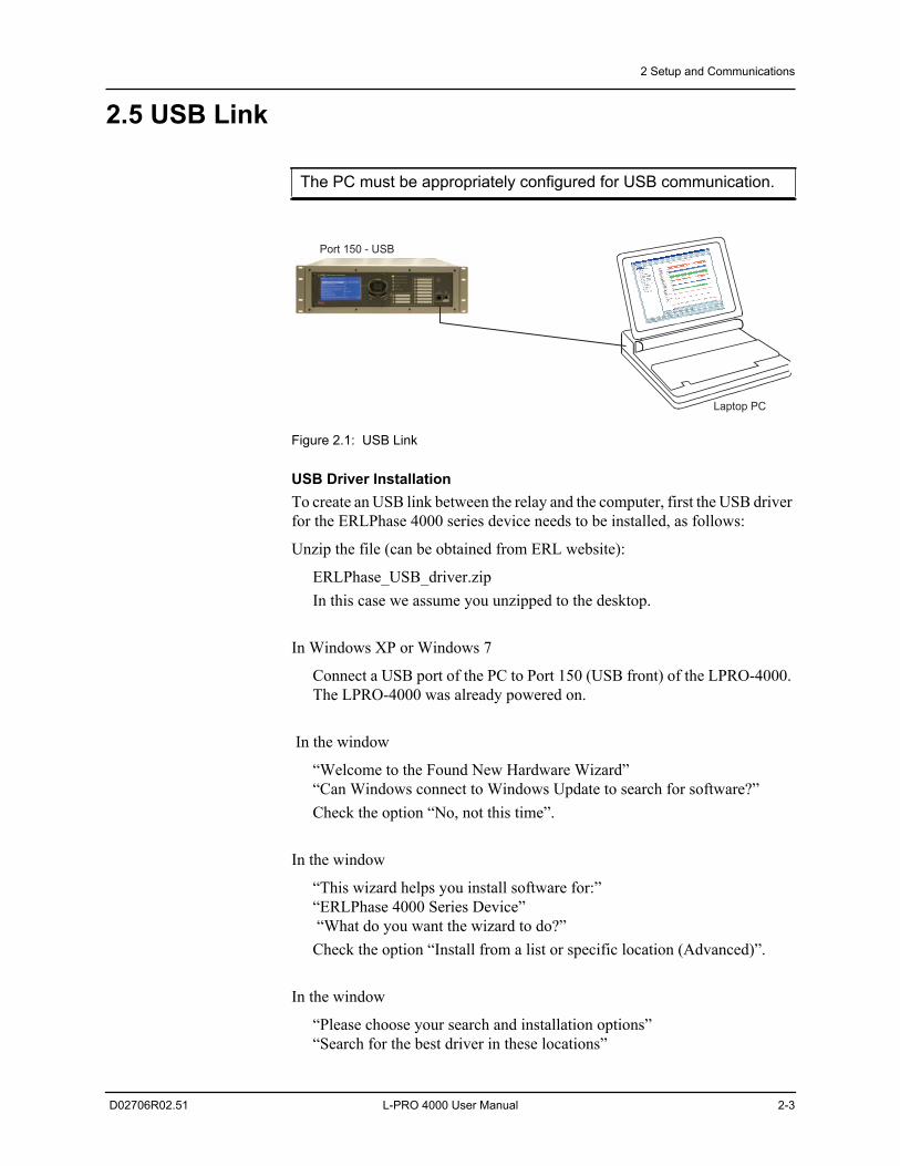
Figure 2.1: USB Link
USB Driver InstallationTo create an USB link between the relay and the computer, first the USB driver for the ERLPhase 4000 series device needs to be installed, as follows:
Unzip the file (can be obtained from ERL website):
ERLPhase_USB_driver.zipIn this case we assume you unzipped to the desktop.
In Windows XP or Windows 7
Connect a USB port of the PC to Port 150 (USB front) of the LPRO-4000. The LPRO-4000 was already powered on.
In the window
“Welcome to the Found New Hardware Wizard”“Can Windows connect to Windows Update to search for software?”Check the option “No, not this time”.
In the window
“This wizard helps you install software for:”“ERLPhase 4000 Series Device” “What do you want the wizard to do?”Check the option “Install from a list or specific location (Advanced)”.
In the window
“Please choose your search and installation options”“Search for the best driver in these locations”
The PC must be appropriately configured for USB communication.
Port 150 - USB
Laptop PC
2 Setup and Communications
2-4 L-PRO 4000 User Manual D02706R02.51
Uncheck the option “Search removable media (floppy, CD-ROM.)”.Check the option “Include this location in the search”.Browse for the following folder:C:\WINDOWS\tiinst\TUSB3410
In the window
“Hardware Installation”“The software you are installing for this hardware”“ERLPhase 4000 Series Device”“has not passed Windows Logo testing to verify its compatibility with Windows XP” or “Windows can’t verify the publisher”Hit Continue Anyway.
In the window
“Completing the Found New Hardware Wizard”“The wizard has finished installing the software for”
“ERLPhase 4000 Series Device”Hit Finish.
To verify the installation was successful, and to which comm port is the ERL-Phase 4000 Series Device configured, do the following:
In Windows XP
Start > Control Panel->Performance and Maintenance->System >Hard-ware > Device Manager > Portsor (if using Control Panel’s Classic View)Start > Control Panel > System > Hardware >Device Manager >Ports
In Windows 7 ‘small icons’ view, go to
Start>Control Panel>Device Manager>Ports.
Look for the port number associated to this device.
“ERLPhase 4000 Series Device”Look for a COM#, where “#” can be 1, 2, 3, etc. Leave the default settings for this port.
It is recommended to restart the PC after the USB driver installation.
The default baud rate for the relay USB Port 150 is 115200, however to double check it login to the relay display and go to:
Main Menu > System > Relay Comm Setup
2 Setup and Communications
D02706R02.51 L-PRO 4000 User Manual 2-5
2.6 Network Link
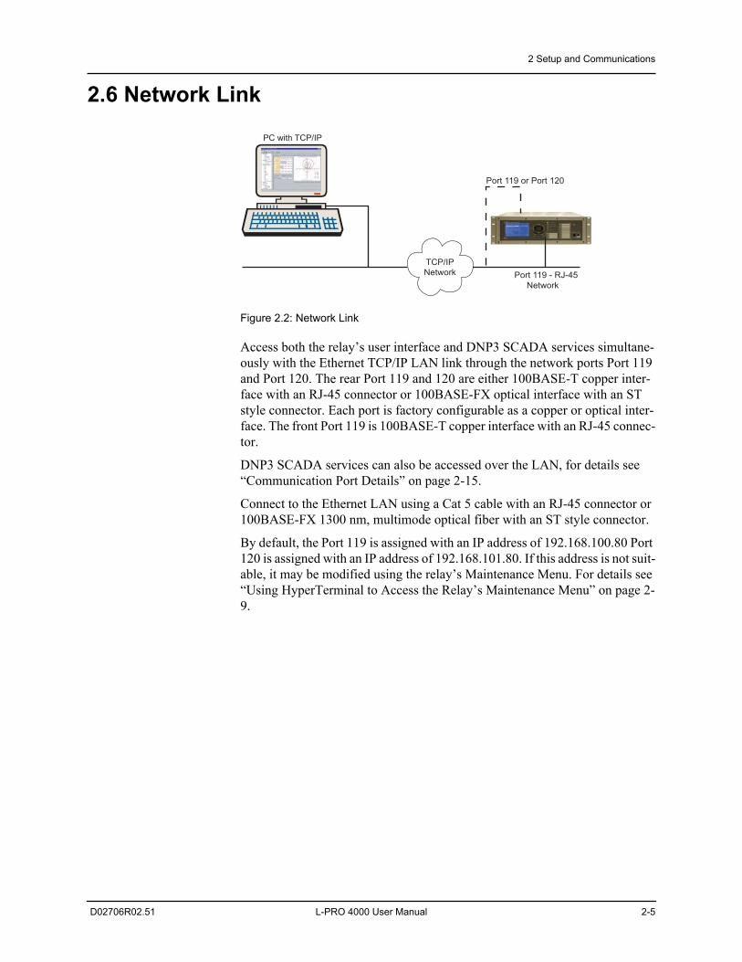
Figure 2.2: Network Link
Access both the relay’s user interface and DNP3 SCADA services simultane-ously with the Ethernet TCP/IP LAN link through the network ports Port 119 and Port 120. The rear Port 119 and 120 are either 100BASE-T copper inter-face with an RJ-45 connector or 100BASE-FX optical interface with an ST style connector. Each port is factory configurable as a copper or optical inter-face. The front Port 119 is 100BASE-T copper interface with an RJ-45 connec-tor.
DNP3 SCADA services can also be accessed over the LAN, for details see “Communication Port Details” on page 2-15.
Connect to the Ethernet LAN using a Cat 5 cable with an RJ-45 connector or 100BASE-FX 1300 nm, multimode optical fiber with an ST style connector.
By default, the Port 119 is assigned with an IP address of 192.168.100.80 Port 120 is assigned with an IP address of 192.168.101.80. If this address is not suit-able, it may be modified using the relay’s Maintenance Menu. For details see “Using HyperTerminal to Access the Relay’s Maintenance Menu” on page 2-9.
PC with TCP/IP
TCP/IP
Network Port 119 - RJ-45
Network
Port 119 or Port 120
2 Setup and Communications
2-6 L-PRO 4000 User Manual D02706R02.51
2.7 Direct Serial Link
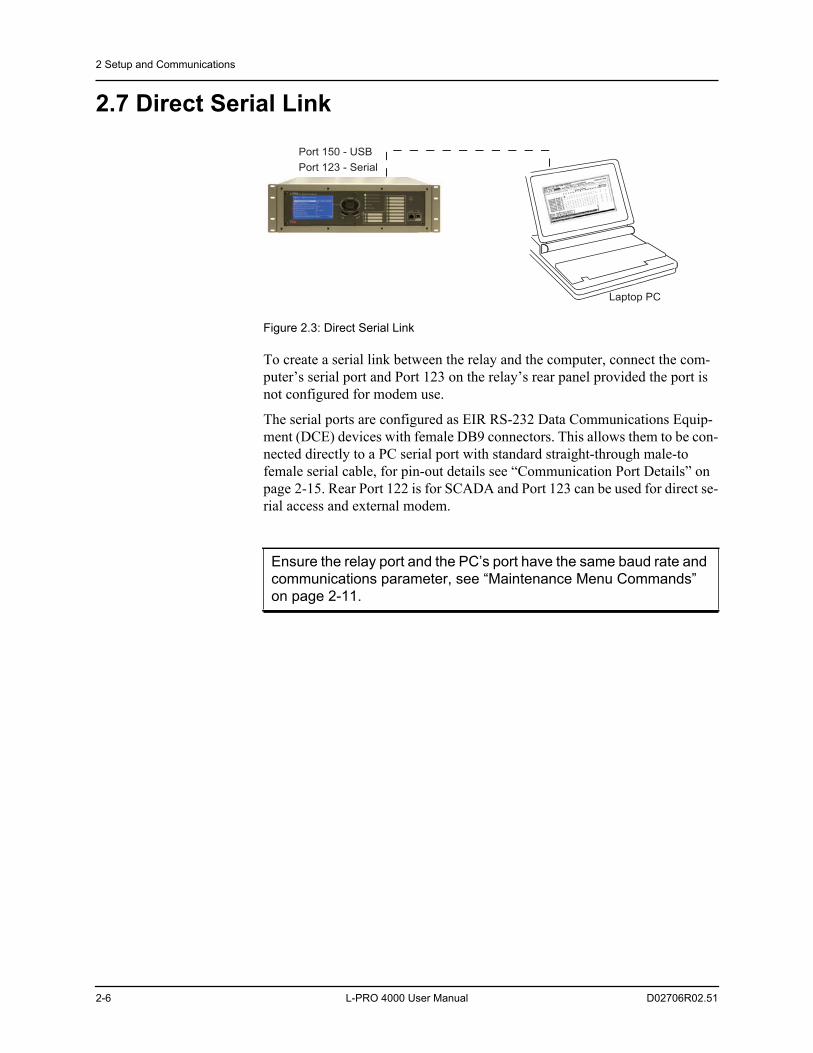
Figure 2.3: Direct Serial Link
To create a serial link between the relay and the computer, connect the com-puter’s serial port and Port 123 on the relay’s rear panel provided the port is not configured for modem use.
The serial ports are configured as EIR RS-232 Data Communications Equip-ment (DCE) devices with female DB9 connectors. This allows them to be con-nected directly to a PC serial port with standard straight-through male-to female serial cable, for pin-out details see “Communication Port Details” on page 2-15. Rear Port 122 is for SCADA and Port 123 can be used for direct se-rial access and external modem.
Ensure the relay port and the PC’s port have the same baud rate and communications parameter, see “Maintenance Menu Commands” on page 2-11.
Laptop PC
Port 123 - Serial
Port 150 - USB
2 Setup and Communications
D02706R02.51 L-PRO 4000 User Manual 2-7
2.8 Modem Link External
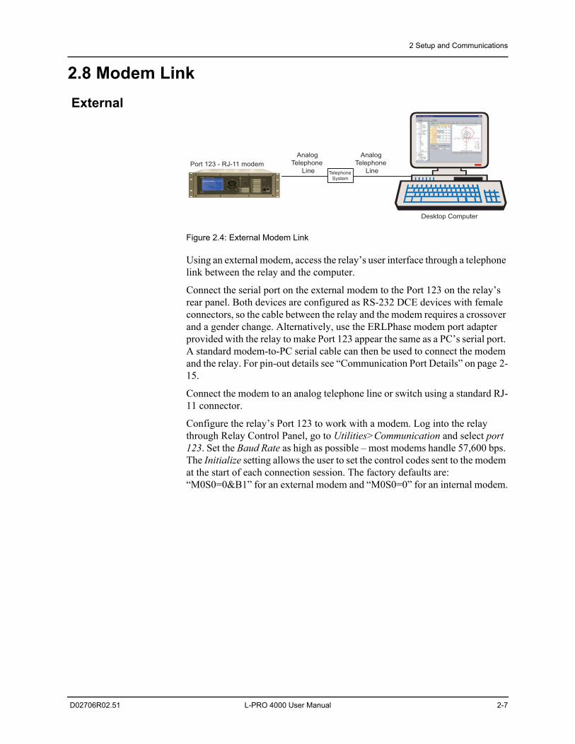
Figure 2.4: External Modem Link
Using an external modem, access the relay’s user interface through a telephone link between the relay and the computer.
Connect the serial port on the external modem to the Port 123 on the relay’s rear panel. Both devices are configured as RS-232 DCE devices with female connectors, so the cable between the relay and the modem requires a crossover and a gender change. Alternatively, use the ERLPhase modem port adapter provided with the relay to make Port 123 appear the same as a PC’s serial port. A standard modem-to-PC serial cable can then be used to connect the modem and the relay. For pin-out details see “Communication Port Details” on page 2-15.
Connect the modem to an analog telephone line or switch using a standard RJ-11 connector.
Configure the relay’s Port 123 to work with a modem. Log into the relay through Relay Control Panel, go to Utilities>Communication and select port 123. Set the Baud Rate as high as possible – most modems handle 57,600 bps. The Initialize setting allows the user to set the control codes sent to the modem at the start of each connection session. The factory defaults are: “M0S0=0&B1” for an external modem and “M0S0=0” for an internal modem.
Desktop Computer
Analog
Telephone
LinePort 123 - RJ-11 modem
Telephone
System
Analog
Telephone
Line
2 Setup and Communications
2-8 L-PRO 4000 User Manual D02706R02.51
Internal
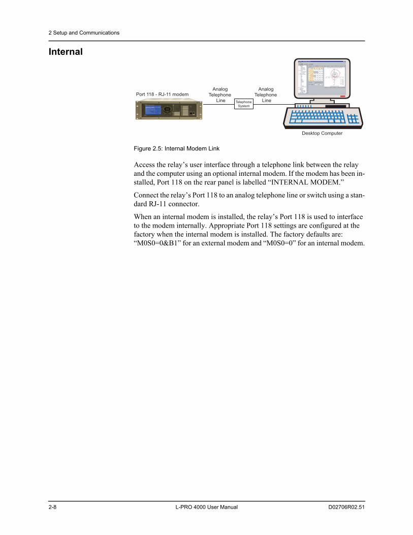
Figure 2.5: Internal Modem Link
Access the relay’s user interface through a telephone link between the relay and the computer using an optional internal modem. If the modem has been in-stalled, Port 118 on the rear panel is labelled “INTERNAL MODEM.”
Connect the relay’s Port 118 to an analog telephone line or switch using a stan-dard RJ-11 connector.
When an internal modem is installed, the relay’s Port 118 is used to interface to the modem internally. Appropriate Port 118 settings are configured at the factory when the internal modem is installed. The factory defaults are: “M0S0=0&B1” for an external modem and “M0S0=0” for an internal modem.
Desktop Computer
Analog
Telephone
Line
Port 118 - RJ-11 modem
Telephone
System
Analog
Telephone
Line
2 Setup and Communications
D02706R02.51 L-PRO 4000 User Manual 2-9
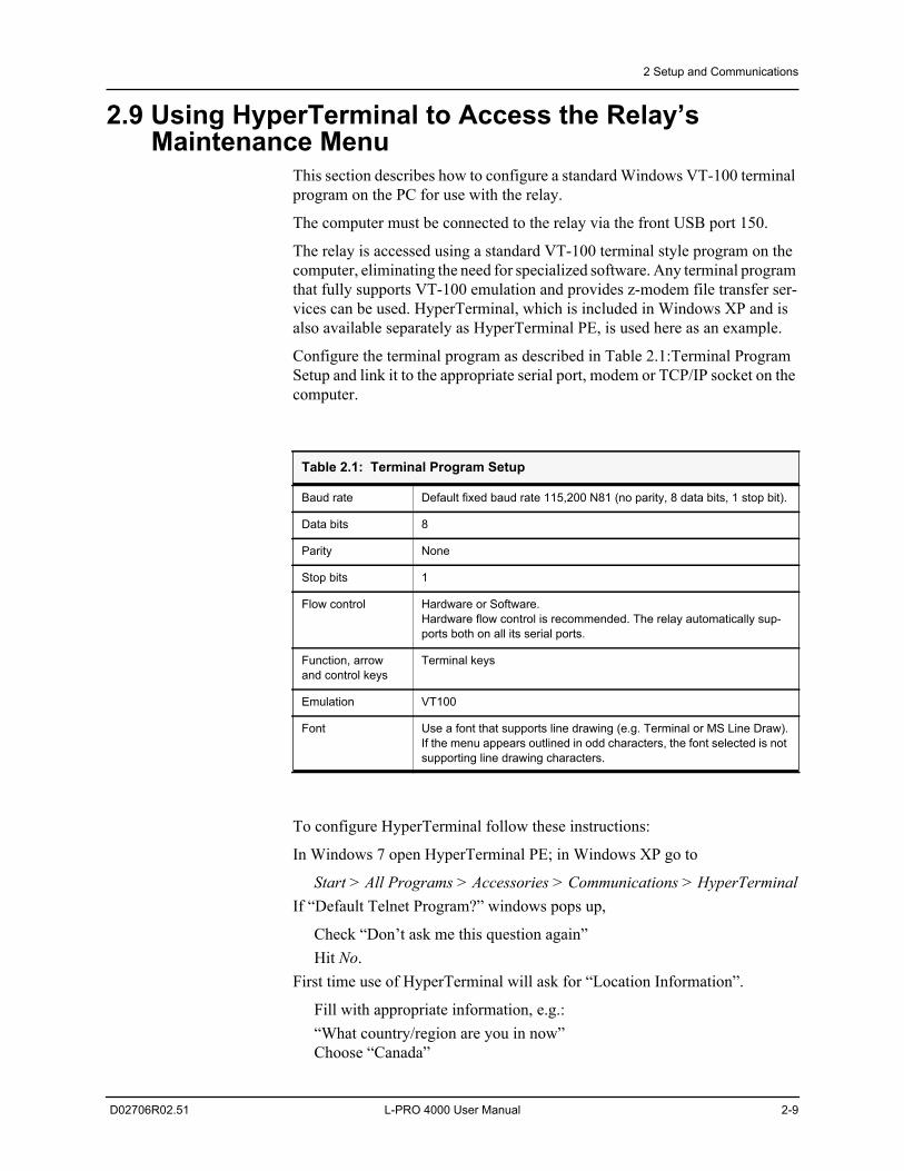
2.9 Using HyperTerminal to Access the Relay’s Maintenance Menu
This section describes how to configure a standard Windows VT-100 terminal program on the PC for use with the relay.
The computer must be connected to the relay via the front USB port 150.
The relay is accessed using a standard VT-100 terminal style program on the computer, eliminating the need for specialized software. Any terminal program that fully supports VT-100 emulation and provides z-modem file transfer ser-vices can be used. HyperTerminal, which is included in Windows XP and is also available separately as HyperTerminal PE, is used here as an example.
Configure the terminal program as described in Table 2.1:Terminal Program Setup and link it to the appropriate serial port, modem or TCP/IP socket on the computer.
To configure HyperTerminal follow these instructions:
In Windows 7 open HyperTerminal PE; in Windows XP go to
Start > All Programs > Accessories > Communications > HyperTerminalIf “Default Telnet Program?” windows pops up,
Check “Don’t ask me this question again”Hit No.
First time use of HyperTerminal will ask for “Location Information”.
Fill with appropriate information, e.g.:“What country/region are you in now”Choose “Canada”
Table 2.1: Terminal Program Setup
Baud rate Default fixed baud rate 115,200 N81 (no parity, 8 data bits, 1 stop bit).
Data bits 8
Parity None
Stop bits 1
Flow control Hardware or Software. Hardware flow control is recommended. The relay automatically sup-ports both on all its serial ports.
Function, arrow and control keys
Terminal keys
Emulation VT100
Font Use a font that supports line drawing (e.g. Terminal or MS Line Draw).If the menu appears outlined in odd characters, the font selected is not supporting line drawing characters.
2 Setup and Communications
2-10 L-PRO 4000 User Manual D02706R02.51
“What area code (or city code) are you are in now?”Enter “306”“If you need to specify a carrier code, what is it?”Enter “”, i.e. leave blank“If you dial a number to access an outside line, what is it?”Enter “”.“The phone system at this location uses:”Choose “Tone dialing”.Hit OK.
First time use of HyperTerminal will show “Phone and Modem Options”.
Hit Cancel.
HyperTerminal will show initially “Connection Description”.
Enter a name for the relay, e.g: “LPRO4000”.Hit OK.
In the window “Connect To”
“Connect using”Choose “COM#”, where “#” was obtained previously in Section 2.5 USB Link, after installing the USB driver.Let’s assume in this case it is COM3.
In the window “COM3 Properties” choose:
“115200”“8”“None”“1”“Hardware”Hit Apply then hit OK
At this time the connection should already be established.
Hit Enter in the terminal window.
2 Setup and Communications
D02706R02.51 L-PRO 4000 User Manual 2-11
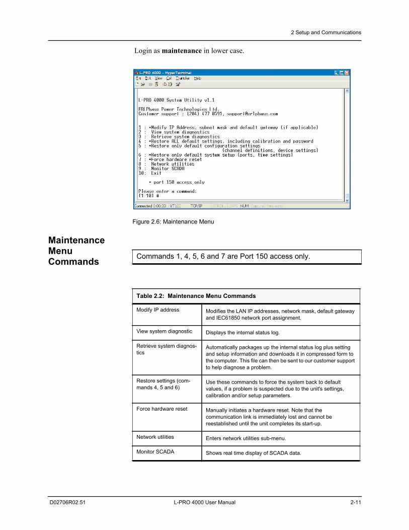
Login as maintenance in lower case.
Figure 2.6: Maintenance Menu
Maintenance Menu Commands Commands 1, 4, 5, 6 and 7 are Port 150 access only.
Table 2.2: Maintenance Menu Commands
Modify IP address Modifies the LAN IP addresses, network mask, default gateway and IEC61850 network port assignment.
View system diagnostic Displays the internal status log.
Retrieve system diagnos-tics
Automatically packages up the internal status log plus setting and setup information and downloads it in compressed form to the computer. This file can then be sent to our customer support to help diagnose a problem.
Restore settings (com-mands 4, 5 and 6)
Use these commands to force the system back to default values, if a problem is suspected due to the unit's settings, calibration and/or setup parameters.
Force hardware reset Manually initiates a hardware reset. Note that thecommunication link is immediately lost and cannot be reestablished until the unit completes its start-up.
Network utilities Enters network utilities sub-menu.
Monitor SCADA Shows real time display of SCADA data.
2 Setup and Communications
2-12 L-PRO 4000 User Manual D02706R02.51
2.10 Firmware UpdateThe relay has an update login that can be accessed by a connection through a VT100 terminal emulator (such as HyperTerminal). This login is available only from Port 150.
1. Use the terminal program to connect to Port 150.2. Select Enter, the terminal responds with a login prompt.3. Login as update in lower case.
The firmware update is used to update the relay’s software with maintenance or enhancement releases. Please see the L-PRO Firmware Update Procedure documentation that comes with the firmware update for instructions on how to update the firmware on the relay.
Table 2.3: Network Utilities Menu Commands
View protocol statistics View IP, TCP and UDP statistics
View active socket states View current states of active sockets
View routing tables View routing tables
Ping Check network connection to given point
Exit network utilities Exit network utilities menu and return to Maintenance Menu Commands
2 Setup and Communications
D02706R02.51 L-PRO 4000 User Manual 2-13
2.11 Setting the Baud Rate
Direct Serial Link
For a direct serial connection, both the relay and the computer must be set to the same baud rate. To change the baud rate of a relay serial port:1. The user needs to log into the relay as Change (any port) or Service (USB
port only) using RCP.2. Then choose Utilities>Communication tab.
Modem Link Unlike a direct serial link, the baud rates for a modem link do not have to be the same on the computer and on the relay. The modems automatically nego-tiate an optimal baud rate for their communication. The baud rate set on the relay only affects the rate at which the relay commu-nicates with the modem. Similarly, the baud rate set in HyperTerminal only af-fects the rate at which the computer communicates with its modem. Details on how to set these respective baud rates are described above, except that the user modifies the Port 123 baud rate on the relay and the properties of the modem in HyperTerminal.
The baud rate is available on the LCD screen from the top level menu selecting System then Relay Comm Setup.
2 Setup and Communications
2-14 L-PRO 4000 User Manual D02706R02.51
2.12 Accessing the Relay’s SCADA ServicesThe relay supports DNP3 (Level 2) and Modbus SCADA protocols as a stan-dard feature on all ERLPhase relays. DNP3 is available through a direct serial link or the Ethernet LAN on top of either TCP or UDP protocols. The Modbus implementation supports both Remote Terminal Unit (RTU) binary or ASCII modes and is available through a direct serial link.
The relay’s Port 122 is dedicated for use with Modbus or DNP3 serial proto-cols. Port 122 uses standard RS-232 signalling. An external RS-232<->RS-485 converter can also be used to connect to an RS-485 network.
For details on connecting to serial Port 122 see “Communicating with the Re-lay Intelligent Electronic Device (IED)” on page 2-2 and “Communication Port Details” on page 2-15.
The DNP3 protocol can also be run across the Ethernet LAN. Both DNP over TCP and DNP over UDP are supported. For details on connecting to the Ether-net LAN see “Network Link” on page 2-5.
Complete details on the Modbus and DNP3 protocol services can be found in the Appendices, for details see “Modbus RTU Communication Protocol” in Appendix E and “DNP3 Device Profile” in Appendix F
Protocol Selection
To select the desired SCADA protocol go to L-PRO 4000 Offliner SCADA communications section. Select the protocol and set the corresponding param-eters.
Communication Parameters
Port 122’s communication parameters are set in the L-PRO 4000 Offliner SCADA communications section Both the baud rate and the parity bit can be configured. The number of data bits and stop bits are determined automatically by the selected SCADA protocol. Modbus ASCII uses 7 data bits. Modbus RTU and DNP Serial use 8 data bits. All protocols use 1 stop bit except in the case where either Modbus protocol is used with no parity; this uses 2 stop bits, as defined in the Modbus standard.
Diagnostics Protocol monitor utilities are available to assist in resolving SCADA commu-nication difficulties such as incompatible baud rate or addressing. The utilities can be accessed through the Maintenance Menu Commands, see “Maintenance Menu Commands” on page 2-11
2 Setup and Communications
D02706R02.51 L-PRO 4000 User Manual 2-15
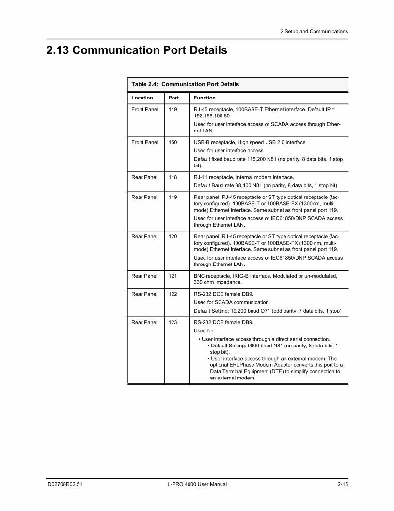
2.13 Communication Port Details
Table 2.4: Communication Port Details
Location Port Function
Front Panel 119 RJ-45 receptacle, 100BASE-T Ethernet interface. Default IP = 192.168.100.80Used for user interface access or SCADA access through Ether-net LAN.
Front Panel 150 USB-B receptacle, High speed USB 2.0 interfaceUsed for user interface accessDefault fixed baud rate 115,200 N81 (no parity, 8 data bits, 1 stop bit).
Rear Panel 118 RJ-11 receptacle, Internal modem interface.Default Baud rate 38,400 N81 (no parity, 8 data bits, 1 stop bit)
Rear Panel 119 Rear panel, RJ-45 receptacle or ST type optical receptacle (fac-tory configured). 100BASE-T or 100BASE-FX (1300nm, multi-mode) Ethernet interface. Same subnet as front panel port 119.Used for user interface access or IEC61850/DNP SCADA access through Ethernet LAN.
Rear Panel 120 Rear panel, RJ-45 receptacle or ST type optical receptacle (fac-tory configured). 100BASE-T or 100BASE-FX (1300 nm, multi-mode) Ethernet interface. Same subnet as front panel port 119.Used for user interface access or IEC61850/DNP SCADA access through Ethernet LAN.
Rear Panel 121 BNC receptacle, IRIG-B Interface. Modulated or un-modulated, 330 ohm impedance.
Rear Panel 122 RS-232 DCE female DB9.Used for SCADA communication.Default Setting: 19,200 baud O71 (odd parity, 7 data bits, 1 stop)
Rear Panel 123 RS-232 DCE female DB9. Used for:
• User interface access through a direct serial connection. • Default Setting: 9600 baud N81 (no parity, 8 data bits, 1 stop bit).
• User interface access through an external modem. The optional ERLPhase Modem Adapter converts this port to a Data Terminal Equipment (DTE) to simplify connection to an external modem.
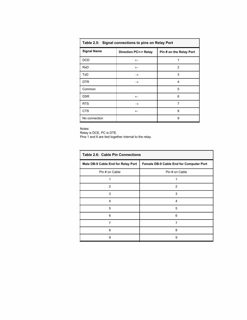
Notes:Relay is DCE, PC is DTE.Pins 1 and 6 are tied together internal to the relay.
Table 2.5: Signal connections to pins on Relay Port
Signal Name Direction PC<-> Relay Pin # on the Relay Port
DCD 1
RxD 2
TxD 3
DTR 4
Common 5
DSR 6
RTS 7
CTS 8
No connection 9
Table 2.6: Cable Pin Connections
Male DB-9 Cable End for Relay Port Female DB-9 Cable End for Computer Port
Pin # on Cable Pin # on Cable
1 1
2 2
3 3
4 4
5 5
6 6
7 7
8 8
9 9
2 Setup and Communications
D02706R02.51 L-PRO 4000 User Manual 2-17
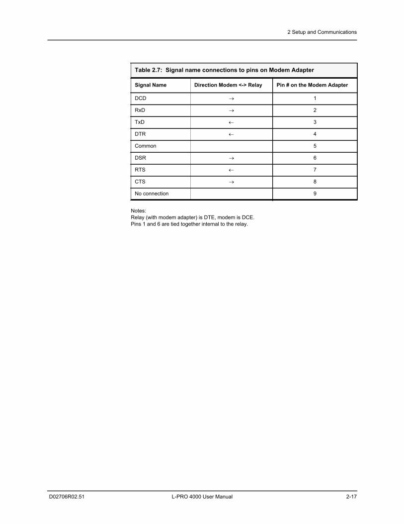
Notes:Relay (with modem adapter) is DTE, modem is DCE.Pins 1 and 6 are tied together internal to the relay.
Table 2.7: Signal name connections to pins on Modem Adapter
Signal Name Direction Modem <-> Relay Pin # on the Modem Adapter
DCD 1
RxD 2
TxD 3
DTR 4
Common 5
DSR 6
RTS 7
CTS 8
No connection 9

D02706R02.51 L-PRO 4000 User Manual 3-1
3 Using the IED (Getting Started)
3.1 IntroductionThis section provides information on the start-up sequence and ways to inter-face with the relay. Descriptions of the Front Panel Display, Terminal Mode and Metering Data are provided.
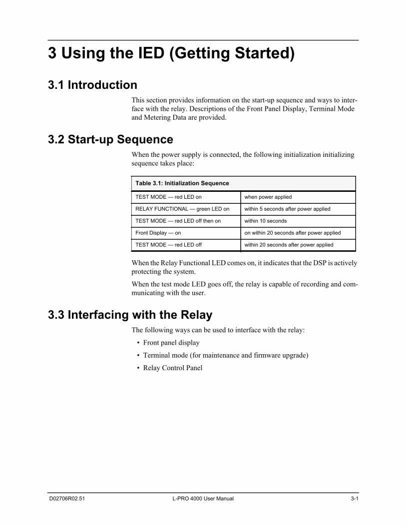
3.2 Start-up SequenceWhen the power supply is connected, the following initialization initializing sequence takes place:
When the Relay Functional LED comes on, it indicates that the DSP is actively protecting the system.
When the test mode LED goes off, the relay is capable of recording and com-municating with the user.
3.3 Interfacing with the RelayThe following ways can be used to interface with the relay:
• Front panel display
• Terminal mode (for maintenance and firmware upgrade)
• Relay Control Panel
Table 3.1: Initialization Sequence
TEST MODE — red LED on when power applied
RELAY FUNCTIONAL — green LED on within 5 seconds after power applied
TEST MODE — red LED off then on within 10 seconds
Front Display — on on within 20 seconds after power applied
TEST MODE — red LED off within 20 seconds after power applied
3 Using the IED (Getting Started)
3-2 L-PRO 4000 User Manual D02706R02.51
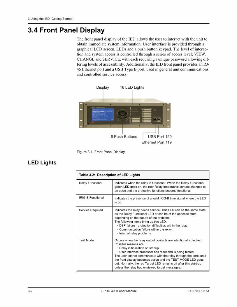
3.4 Front Panel DisplayThe front panel display of the IED allows the user to interact with the unit to obtain immediate system information. User interface is provided through a graphical LCD screen, LEDs and a push button keypad. The level of interac-tion and system access is controlled through a series of access level; VIEW, CHANGE and SERVICE, with each requiring a unique password allowing dif-fering levels of accessibility. Additionally, the IED front panel provides an RJ-45 Ethernet port and a USB Type B port, used in general unit communications and controlled service access.
Figure 3.1: Front Panel Display
LED Lights
6 Push Buttons
Display 16 LED Lights
USB Port 150
Ethernet Port 119
Table 3.2: Description of LED Lights
Relay Functional Indicates when the relay is functional. When the Relay Functional green LED goes on, the rear Relay Inoperative contact changes to an open and the protective functions become functional.
IRIG-B Functional Indicates the presence of a valid IRIG-B time signal where the LED is on.
Service Required Indicates the relay needs service. This LED can be the same state as the Relay Functional LED or can be of the opposite state depending on the nature of the problem. The following items bring up this LED:
• DSP failure - protection difficulties within the relay.• Communication failure within the relay.• Internal relay problems.
Test Mode Occurs when the relay output contacts are intentionally blocked. Possible reasons are:
• Relay initialization on startup• User interface processor has reset and is being tested.
The user cannot communicate with the relay through the ports until the front display becomes active and the TEST MODE LED goes out. Normally, the red Target LED remains off after this start-up unless the relay had unviewed target messages.
3 Using the IED (Getting Started)
D02706R02.51 L-PRO 4000 User Manual 3-3
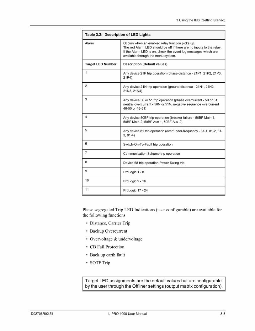
Phase segregated Trip LED Indications (user configurable) are available for the following functions
• Distance, Carrier Trip
• Backup Overcurrent
• Overvoltage & undervoltage
• CB Fail Protection
• Back up earth fault
• SOTF Trip
Alarm Occurs when an enabled relay function picks up.The red Alarm LED should be off if there are no inputs to the relay. If the Alarm LED is on, check the event log messages which are available through the menu system.
Target LED Number Description (Default values)
1 Any device 21P trip operation (phase distance - 21P1, 21P2, 21P3, 21P4)
2 Any device 21N trip operation (ground distance - 21N1, 21N2, 21N3, 21N4)
3 Any device 50 or 51 trip operation (phase overcurrent - 50 or 51, neutral overcurrent - 50N or 51N, negative sequence overcurrent 46-50 or 46-51)
4 Any device 50BF trip operation (breaker failure - 50BF Main-1, 50BF Main-2, 50BF Aux-1, 50BF Aux-2)
5 Any device 81 trip operation (over/under-frequency - 81-1, 81-2, 81-3, 81-4)
6 Switch-On-To-Fault trip operation
7 Communication Scheme trip operation
8 Device 68 trip operation Power Swing trip
9 ProLogic 1 - 8
10 ProLogic 9 - 16
11 ProLogic 17 - 24
Target LED assignments are the default values but are configurable by the user through the Offliner settings (output matrix configuration).
Table 3.2: Description of LED Lights
3 Using the IED (Getting Started)
3-4 L-PRO 4000 User Manual D02706R02.51
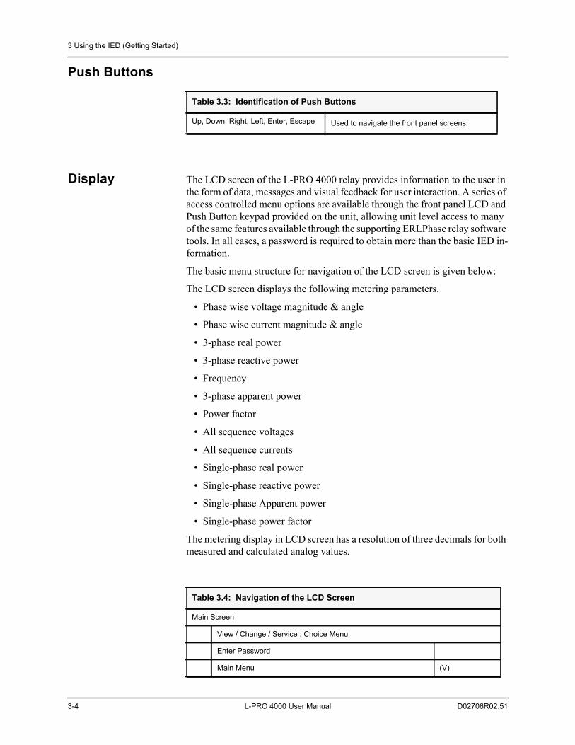
Push Buttons
Display The LCD screen of the L-PRO 4000 relay provides information to the user in the form of data, messages and visual feedback for user interaction. A series of access controlled menu options are available through the front panel LCD and Push Button keypad provided on the unit, allowing unit level access to many of the same features available through the supporting ERLPhase relay software tools. In all cases, a password is required to obtain more than the basic IED in-formation.
The basic menu structure for navigation of the LCD screen is given below:
The LCD screen displays the following metering parameters.
• Phase wise voltage magnitude & angle
• Phase wise current magnitude & angle
• 3-phase real power
• 3-phase reactive power
• Frequency
• 3-phase apparent power
• Power factor
• All sequence voltages
• All sequence currents
• Single-phase real power
• Single-phase reactive power
• Single-phase Apparent power
• Single-phase power factor
The metering display in LCD screen has a resolution of three decimals for both measured and calculated analog values.
Table 3.3: Identification of Push Buttons
Up, Down, Right, Left, Enter, Escape Used to navigate the front panel screens.
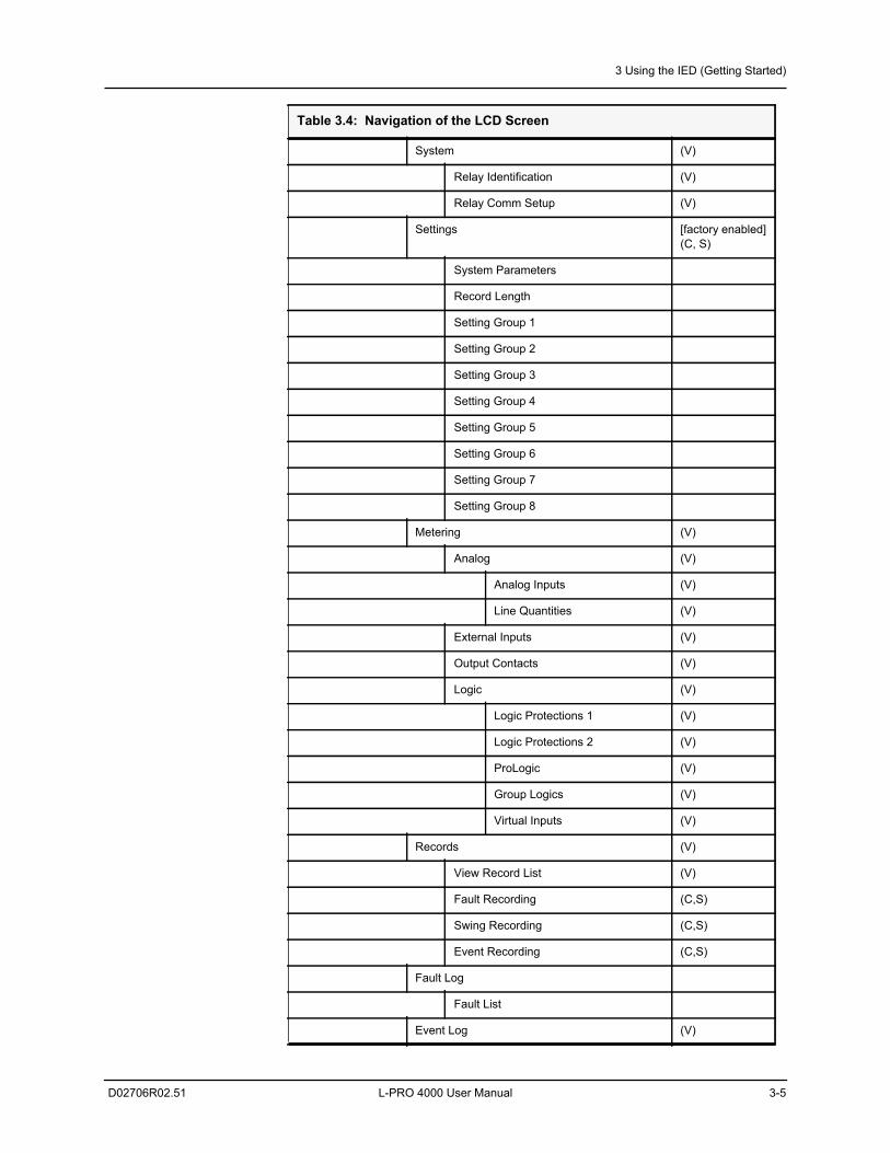
Table 3.4: Navigation of the LCD Screen
Main Screen
View / Change / Service : Choice Menu
Enter Password
Main Menu (V)
3 Using the IED (Getting Started)
D02706R02.51 L-PRO 4000 User Manual 3-5
System (V)
Relay Identification (V)
Relay Comm Setup (V)
Settings [factory enabled](C, S)
System Parameters
Record Length
Setting Group 1
Setting Group 2
Setting Group 3
Setting Group 4
Setting Group 5
Setting Group 6
Setting Group 7
Setting Group 8
Metering (V)
Analog (V)
Analog Inputs (V)
Line Quantities (V)
External Inputs (V)
Output Contacts (V)
Logic (V)
Logic Protections 1 (V)
Logic Protections 2 (V)
ProLogic (V)
Group Logics (V)
Virtual Inputs (V)
Records (V)
View Record List (V)
Fault Recording (C,S)
Swing Recording (C,S)
Event Recording (C,S)
Fault Log
Fault List
Event Log (V)
Table 3.4: Navigation of the LCD Screen
3 Using the IED (Getting Started)
3-6 L-PRO 4000 User Manual D02706R02.51
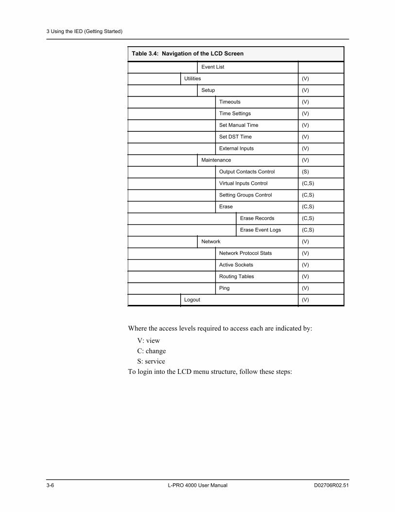
Where the access levels required to access each are indicated by:
V: viewC: changeS: service
To login into the LCD menu structure, follow these steps:
Event List
Utilities (V)
Setup (V)
Timeouts (V)
Time Settings (V)
Set Manual Time (V)
Set DST Time (V)
External Inputs (V)
Maintenance (V)
Output Contacts Control (S)
Virtual Inputs Control (C,S)
Setting Groups Control (C,S)
Erase (C,S)
Erase Records (C,S)
Erase Event Logs (C,S)
Network (V)
Network Protocol Stats (V)
Active Sockets (V)
Routing Tables (V)
Ping (V)
Logout (V)
Table 3.4: Navigation of the LCD Screen
3 Using the IED (Getting Started)
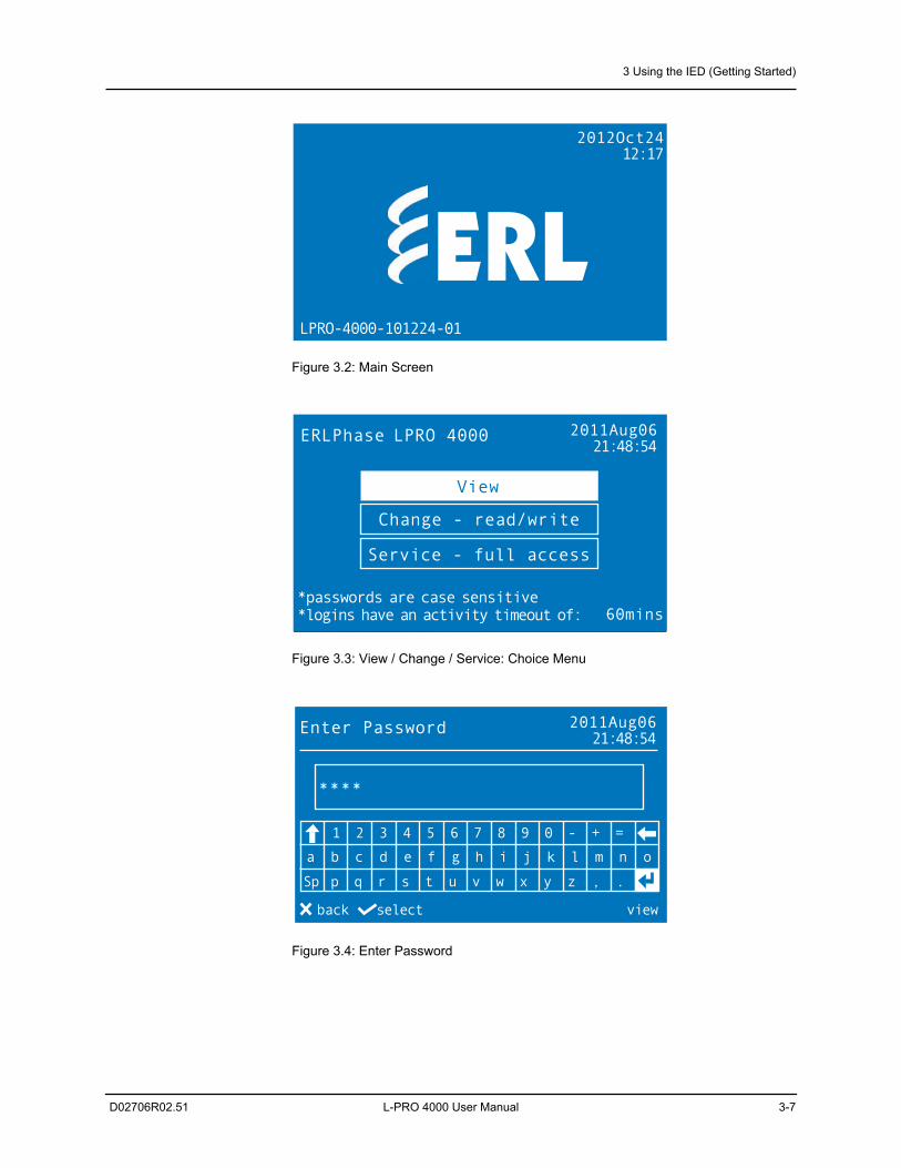
D02706R02.51 L-PRO 4000 User Manual 3-7
Figure 3.2: Main Screen
Figure 3.3: View / Change / Service: Choice Menu
Figure 3.4: Enter Password
2012Oct2412:17
LPRO-4000-101224-01
ERLPhase LPRO 4000 2011Aug0621:48:54
*passwords are case sensitive*logins have an activity timeout of: 60mins
View
Change - read/write
Service - full access
1 2 3 4 5 6 7 8 9 0 - + =
a b c d e f g h i j k l m n o
Enter Password 2011Aug0621:48:54
select view
Sp p q r s t u v w x y z , .
back
****
3 Using the IED (Getting Started)
3-8 L-PRO 4000 User Manual D02706R02.51
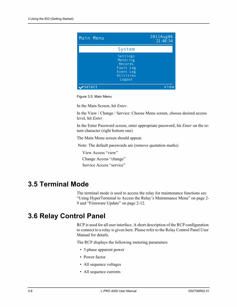
Figure 3.5: Main Menu
In the Main Screen, hit Enter.
In the View / Change / Service: Choose Menu screen, choose desired access level, hit Enter.
In the Enter Password screen, enter appropriate password, hit Enter on the re-turn character (right bottom one)
The Main Menu screen should appear.
Note: The default passwords are (remove quotation marks)
View Access “view”Change Access “change”Service Access “service”
3.5 Terminal ModeThe terminal mode is used to access the relay for maintenance functions see “Using HyperTerminal to Access the Relay’s Maintenance Menu” on page 2-9 and “Firmware Update” on page 2-12.
3.6 Relay Control PanelRCP is used for all user interface. A short description of the RCP configuration to connect to a relay is given here. Please refer to the Relay Control Panel User Manual for details.
The RCP displays the following metering parameters
• 3-phase apparent power
• Power factor
• All sequence voltages
• All sequence currents
Main Menu 2011Aug0621:48:54
select view
System
SettingsMeteringRecords
Fault LogEvent LogUtilitiesLogout
3 Using the IED (Getting Started)
D02706R02.51 L-PRO 4000 User Manual 3-9
• Single-phase real power
• Single-phase reactive power
• Single-phase Apparent power
• Single-phase power factor
The metering display in RCP has a resolution of three decimals for both mea-sured and calculated analog values.
Follow this sequence to configure RCP for USB link to the relay.
1. Execute.Relay Control Panel.exe
2. Execute.L-PRO 4000 Offliner.exe
3. Install Null Modem Driver.Please refer to the Relay Control Panel User Manual for details.
4. Run Relay Control Panel.Go to:Start > All Programs > ERLPhase > Relay Control Panel > Relay Control PanelFirst time RCP is run.Hit Add New.“Add New Relay”
Choose Communication > Direct Serial Link.Hit Get Information From Relay.Then RCP will communicate with the LPRO-4000 and retrieve in-formation to fill required fields.When this is done, hit Save Relay. If the window “Relay already exists...” pops up, you may need to re-name the relay changing the “Relay Name” in the “Relay Definition” category, before saving.
After first time, in “Select Relay”, choose relay and hit Connect.In “Relay Password Prompt”
Choose desired access level, enter appropriate passwordNote: Default passwords are listed below (remove the quotation marks)
View Access “view”Change Access “change”Service Access “service”
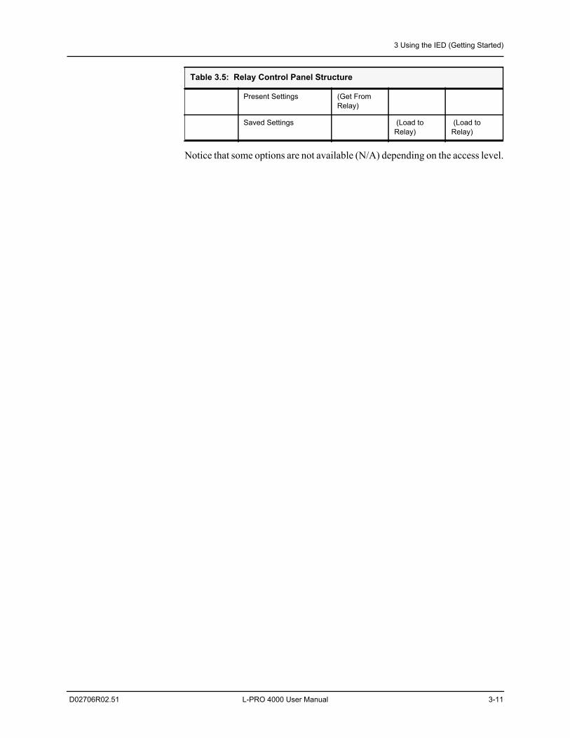
The basic structure of the Relay Control Panel information, including basic actions available, is given below:
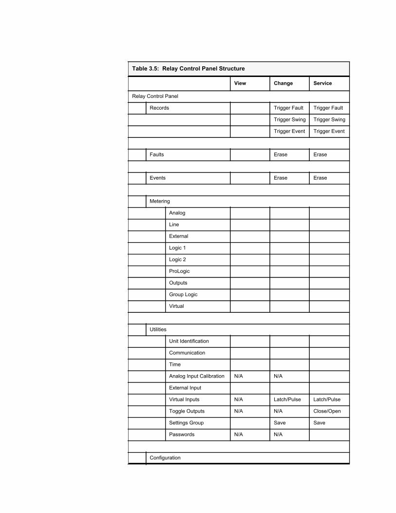
Table 3.5: Relay Control Panel Structure
View Change Service
Relay Control Panel
Records Trigger Fault Trigger Fault
Trigger Swing Trigger Swing
Trigger Event Trigger Event
Faults Erase Erase
Events Erase Erase
Metering
Analog
Line
External
Logic 1
Logic 2
ProLogic
Outputs
Group Logic
Virtual
Utilities
Unit Identification
Communication
Time
Analog Input Calibration N/A N/A
External Input
Virtual Inputs N/A Latch/Pulse Latch/Pulse
Toggle Outputs N/A N/A Close/Open
Settings Group Save Save
Passwords N/A N/A
Configuration
3 Using the IED (Getting Started)
D02706R02.51 L-PRO 4000 User Manual 3-11
Notice that some options are not available (N/A) depending on the access level.
Present Settings (Get From Relay)
Saved Settings (Load to Relay)
(Load to Relay)
Table 3.5: Relay Control Panel Structure

D02706R02.51 L-PRO 4000 User Manual 4-1
4 Protection Functions and Specifications
4.1 Protection and Recording FunctionsIntroduction This section describes the equations and algorithms of the relay protection
functions. All functions with time delay provide an alarm output when their pickup level is exceeded.
The following functions are exceptions: 27 Auxiliary, 27 Main, 59 Auxiliary, 59 Main, 25/27/59 Sync Check, 50LS Main, 50LS Auxiliary, 50BF Main, 50BF Auxiliary, 81 Frequency and ProLogic elements.
A complete list of the settings and their range values can be found in “IED Set-tings and Ranges” in Appendix B.
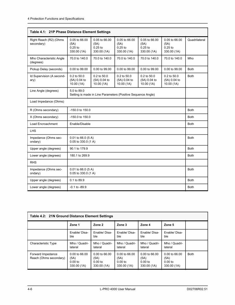
21P Phase/21N Ground Distance
The relay 21P contains 5 zones of phase distance elements; all 5 zones of 21P can be set to either Mho or Quadrilateral type. Note that only one type can be used at a time. The 21P can contain a mixture of Mho and Quadrilateral shapes, for example the 21P1 and 21P2 can be set to a Mho characteristic and the 21P3, 21P4 and 21P5 could be set to a Quadrilateral characteristic.
The relay 21N contains 5 zones of ground distance elements; all 5 zones of 21N can be set to either Mho or Quadrilateral type. Note that only one type can be used at a time. The 21N can contain a mixture of Mho and Quadrilateral shapes, for example the 21N1 and 21N2 can be set to a Mho characteristic and the 21N3, 21N4 and 21N5 could be set to a Quadrilateral characteristic.
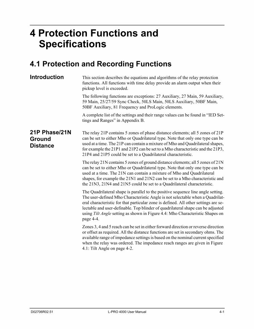
The Quadrilateral shape is parallel to the positive sequence line angle setting. The user-defined Mho Characteristic Angle is not selectable when a Quadrilat-eral characteristic for that particular zone is defined. All other settings are se-lectable and user-definable. Top blinder of quadrilateral shape can be adjusted using Tilt Angle setting as shown in Figure 4.4: Mho Characteristic Shapes on page 4-4.
Zones 3, 4 and 5 reach can be set in either forward direction or reverse direction or offset as required. All the distance functions are set in secondary ohms. The available range of impedance settings is based on the nominal current specified when the relay was ordered. The impedance reach ranges are given in Figure 4.1: Tilt Angle on page 4-2.
4 Protection Functions and Specifications
4-2 L-PRO 4000 User Manual D02706R02.51
Figure 4.1: Tilt Angle
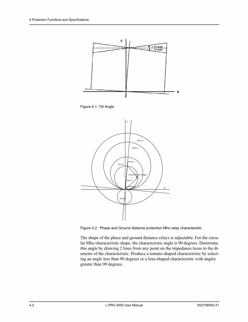
Figure 4.2: Phase and Ground distance protection Mho relay characteristic
The shape of the phase and ground distance relays is adjustable. For the circu-lar Mho characteristic shape, the characteristic angle is 90 degrees. Determine this angle by drawing 2 lines from any point on the impedance locus to the di-ameter of the characteristic. Produce a tomato-shaped characteristic by select-ing an angle less than 90 degrees or a lens-shaped characteristic with angles greater than 90 degrees.
R
X
Zone 5
Zone 3
Zone 2
Zone 1
Zone 4
Line Z1
Line Angle
Characteristic Angle
4 Protection Functions and Specifications
D02706R02.51 L-PRO 4000 User Manual 4-3
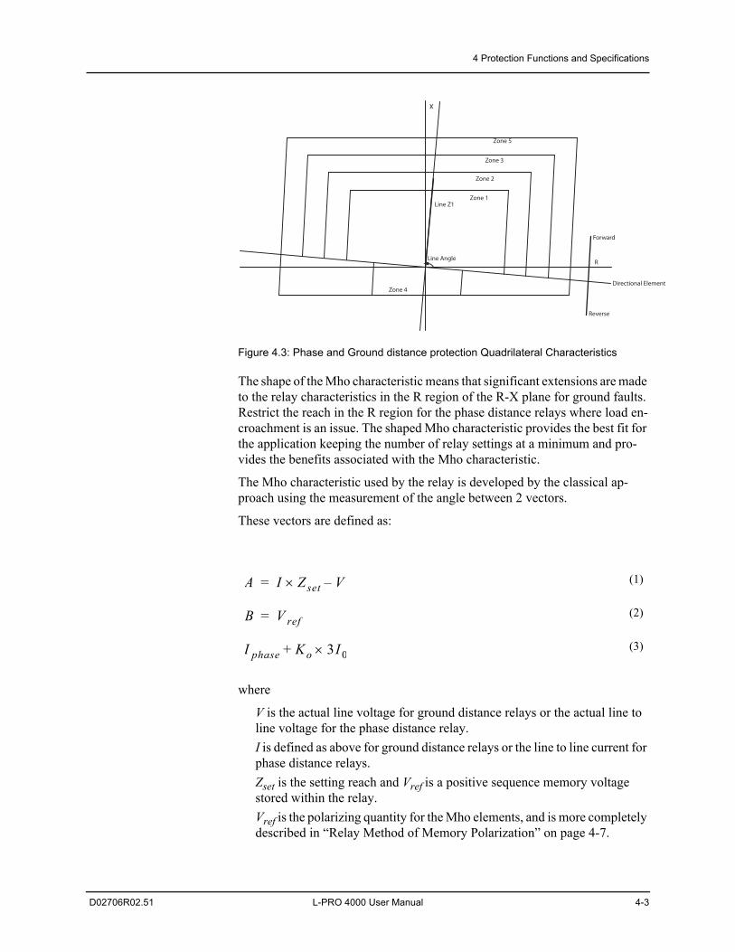
Figure 4.3: Phase and Ground distance protection Quadrilateral Characteristics
The shape of the Mho characteristic means that significant extensions are made to the relay characteristics in the R region of the R-X plane for ground faults. Restrict the reach in the R region for the phase distance relays where load en-croachment is an issue. The shaped Mho characteristic provides the best fit for the application keeping the number of relay settings at a minimum and pro-vides the benefits associated with the Mho characteristic.
The Mho characteristic used by the relay is developed by the classical ap-proach using the measurement of the angle between 2 vectors.
These vectors are defined as:
where
V is the actual line voltage for ground distance relays or the actual line to line voltage for the phase distance relay.I is defined as above for ground distance relays or the line to line current for phase distance relays. Zset is the setting reach and Vref is a positive sequence memory voltage stored within the relay.Vref is the polarizing quantity for the Mho elements, and is more completely described in “Relay Method of Memory Polarization” on page 4-7.
(1)
(2)
(3)
R
X
Zone 5
Zone 3
Zone 2
Zone 1
Zone 4
Line Angle
Line Z1
Forward
Reverse
Directional Element
A I Zset V–=
B V ref=
I phase Ko 3I 0+
4 Protection Functions and Specifications
4-4 L-PRO 4000 User Manual D02706R02.51
To make the reach of the ground distance relay relate to the line positive se-quence impedance the classical Ko factor is used.
This factor is defined as
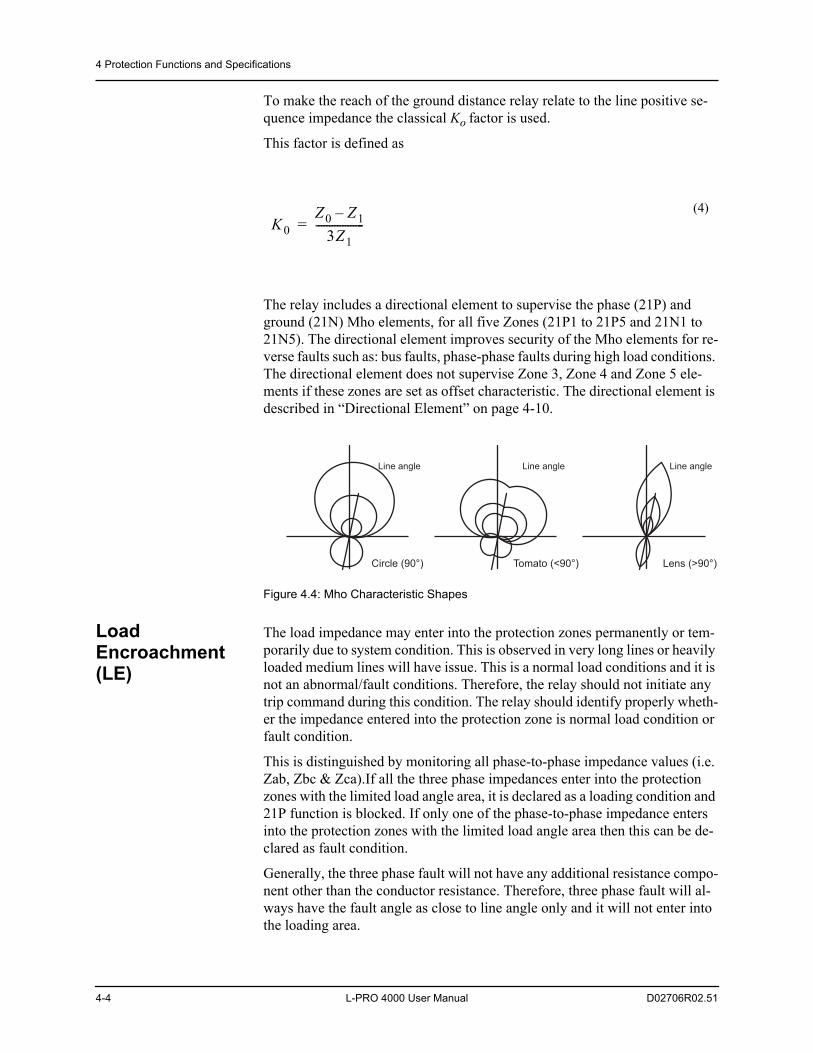
The relay includes a directional element to supervise the phase (21P) and ground (21N) Mho elements, for all five Zones (21P1 to 21P5 and 21N1 to 21N5). The directional element improves security of the Mho elements for re-verse faults such as: bus faults, phase-phase faults during high load conditions. The directional element does not supervise Zone 3, Zone 4 and Zone 5 ele-ments if these zones are set as offset characteristic. The directional element is described in “Directional Element” on page 4-10.
Figure 4.4: Mho Characteristic Shapes
Load Encroachment (LE)
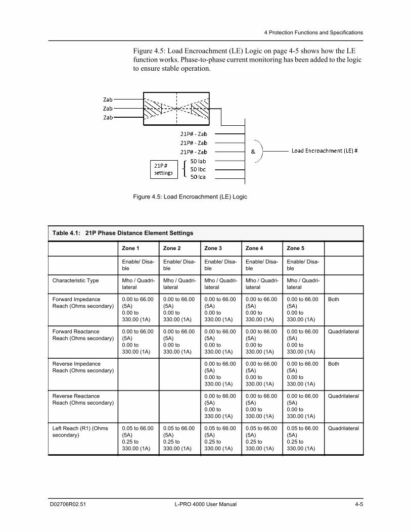
The load impedance may enter into the protection zones permanently or tem-porarily due to system condition. This is observed in very long lines or heavily loaded medium lines will have issue. This is a normal load conditions and it is not an abnormal/fault conditions. Therefore, the relay should not initiate any trip command during this condition. The relay should identify properly wheth-er the impedance entered into the protection zone is normal load condition or fault condition.
This is distinguished by monitoring all phase-to-phase impedance values (i.e. Zab, Zbc & Zca).If all the three phase impedances enter into the protection zones with the limited load angle area, it is declared as a loading condition and 21P function is blocked. If only one of the phase-to-phase impedance enters into the protection zones with the limited load angle area then this can be de-clared as fault condition.
Generally, the three phase fault will not have any additional resistance compo-nent other than the conductor resistance. Therefore, three phase fault will al-ways have the fault angle as close to line angle only and it will not enter into the loading area.
(4)K0
Z0 Z1–3Z1
------------------=
Line angle
Circle (90°)
Line angle
Tomato (<90°)
Line angle
Lens (>90°)
4 Protection Functions and Specifications
D02706R02.51 L-PRO 4000 User Manual 4-5
Figure 4.5: Load Encroachment (LE) Logic on page 4-5 shows how the LE function works. Phase-to-phase current monitoring has been added to the logic to ensure stable operation.
Figure 4.5: Load Encroachment (LE) Logic
Table 4.1: 21P Phase Distance Element Settings
Zone 1 Zone 2 Zone 3 Zone 4 Zone 5
Enable/ Disa-ble
Enable/ Disa-ble
Enable/ Disa-ble
Enable/ Disa-ble
Enable/ Disa-ble
Characteristic Type Mho / Quadri-lateral
Mho / Quadri-lateral
Mho / Quadri-lateral
Mho / Quadri-lateral
Mho / Quadri-lateral
Forward Impedance Reach (Ohms secondary)
0.00 to 66.00 (5A)0.00 to 330.00 (1A)
0.00 to 66.00 (5A)0.00 to 330.00 (1A)
0.00 to 66.00 (5A)0.00 to 330.00 (1A)
0.00 to 66.00 (5A)0.00 to 330.00 (1A)
0.00 to 66.00 (5A)0.00 to 330.00 (1A)
Both
Forward Reactance Reach (Ohms secondary)
0.00 to 66.00 (5A)0.00 to 330.00 (1A)
0.00 to 66.00 (5A)0.00 to 330.00 (1A)
0.00 to 66.00 (5A)0.00 to 330.00 (1A)
0.00 to 66.00 (5A)0.00 to 330.00 (1A)
0.00 to 66.00 (5A)0.00 to 330.00 (1A)
Quadrilateral
Reverse Impedance Reach (Ohms secondary)
0.00 to 66.00 (5A)0.00 to 330.00 (1A)
0.00 to 66.00 (5A)0.00 to 330.00 (1A)
0.00 to 66.00 (5A)0.00 to 330.00 (1A)
Both
Reverse Reactance Reach (Ohms secondary)
0.00 to 66.00 (5A)0.00 to 330.00 (1A)
0.00 to 66.00 (5A)0.00 to 330.00 (1A)
0.00 to 66.00 (5A)0.00 to 330.00 (1A)
Quadrilateral
Left Reach (R1) (Ohms secondary)
0.05 to 66.00 (5A)0.25 to 330.00 (1A)
0.05 to 66.00 (5A)0.25 to 330.00 (1A)
0.05 to 66.00 (5A)0.25 to 330.00 (1A)
0.05 to 66.00 (5A)0.25 to 330.00 (1A)
0.05 to 66.00 (5A)0.25 to 330.00 (1A)
Quadrilateral
4 Protection Functions and Specifications
4-6 L-PRO 4000 User Manual D02706R02.51
Right Reach (R2) (Ohms secondary)
0.05 to 66.00 (5A)0.25 to 330.00 (1A)
0.05 to 66.00 (5A)0.25 to 330.00 (1A)
0.05 to 66.00 (5A)0.25 to 330.00 (1A)
0.05 to 66.00 (5A)0.25 to 330.00 (1A)
0.05 to 66.00 (5A)0.25 to 330.00 (1A)
Quadrilateral
Mho Characteristic Angle (degrees)
70.0 to 140.0 70.0 to 140.0 70.0 to 140.0 70.0 to 140.0 70.0 to 140.0 Mho
Pickup Delay (seconds) 0.00 to 99.00 0.00 to 99.00 0.00 to 99.00 0.00 to 99.00 0.00 to 99.00 Both
Id Supervision (A second-ary)
0.2 to 50.0 (5A) 0.04 to 10.00 (1A)
0.2 to 50.0 (5A) 0.04 to 10.00 (1A)
0.2 to 50.0 (5A) 0.04 to 10.00 (1A)
0.2 to 50.0 (5A) 0.04 to 10.00 (1A)
0.2 to 50.0 (5A) 0.04 to 10.00 (1A)
Both
Line Angle (degrees) 5.0 to 89.0 Setting is made in Line Parameters (Positive Sequence Angle)
Load Impedance (Ohms)
R (Ohms secondary) -150.0 to 150.0 Both
X (Ohms secondary) -150.0 to 150.0 Both
Load Encroachment Enable/Disable Both
LHS
Impedance (Ohms sec-ondary)
0.01 to 66.0 (5 A)0.05 to 330.0 (1 A)
Both
Upper angle (degrees) 90.1 to 179.9 Both
Lower angle (degrees) 180.1 to 269.9 Both
RHS
Impedance (Ohms sec-ondary)
0.01 to 66.0 (5 A)0.05 to 330.0 (1 A)
Both
Upper angle (degrees) 0.1 to 89.9 Both
Lower angle (degrees) -0.1 to -89.9 Both
Table 4.1: 21P Phase Distance Element Settings
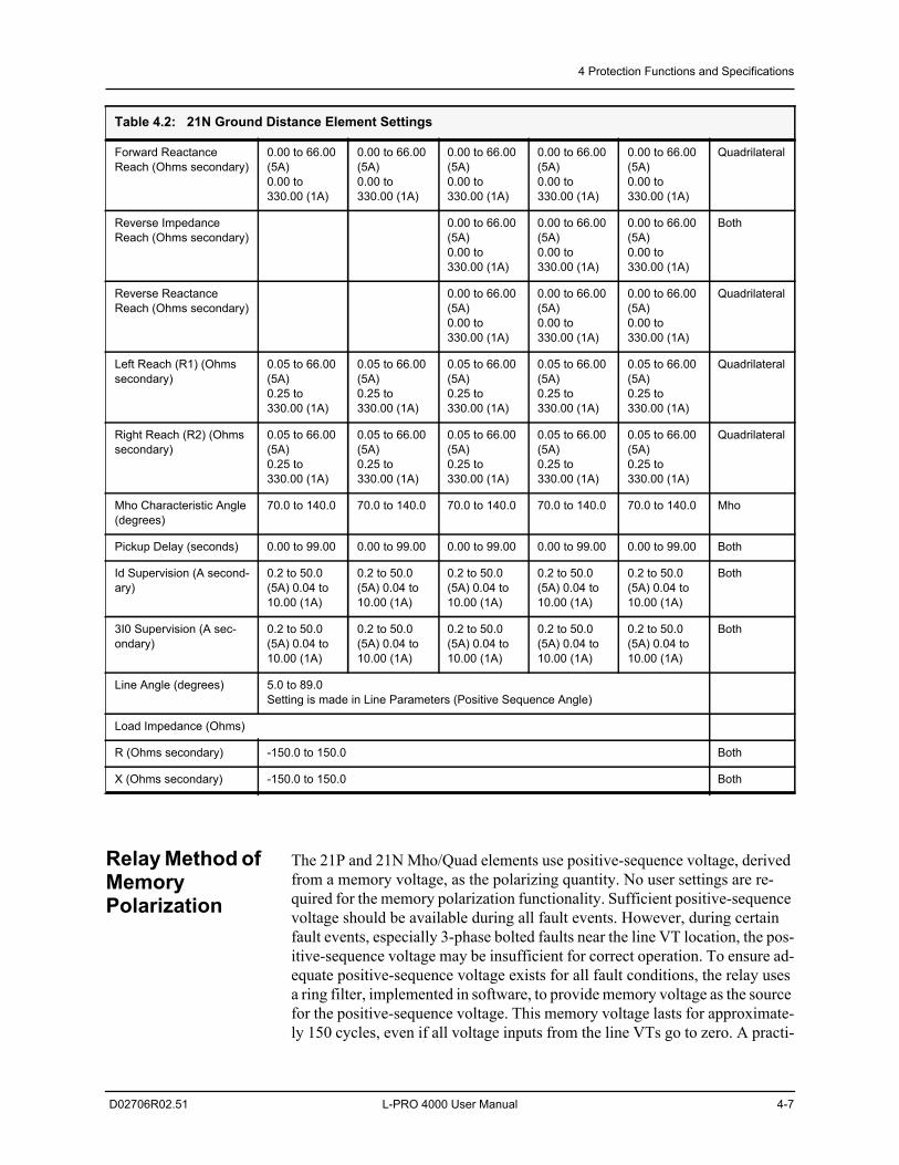
Table 4.2: 21N Ground Distance Element Settings
Zone 1 Zone 2 Zone 3 Zone 4 Zone 5
Enable/ Disa-ble
Enable/ Disa-ble
Enable/ Disa-ble
Enable/ Disa-ble
Enable/ Disa-ble
Characteristic Type Mho / Quadri-lateral
Mho / Quadri-lateral
Mho / Quadri-lateral
Mho / Quadri-lateral
Mho / Quadri-lateral
Forward Impedance Reach (Ohms secondary)
0.00 to 66.00 (5A)0.00 to 330.00 (1A)
0.00 to 66.00 (5A)0.00 to 330.00 (1A)
0.00 to 66.00 (5A)0.00 to 330.00 (1A)
0.00 to 66.00 (5A)0.00 to 330.00 (1A)
0.00 to 66.00 (5A)0.00 to 330.00 (1A)
Both
4 Protection Functions and Specifications
D02706R02.51 L-PRO 4000 User Manual 4-7
Relay Method of Memory Polarization
The 21P and 21N Mho/Quad elements use positive-sequence voltage, derived from a memory voltage, as the polarizing quantity. No user settings are re-quired for the memory polarization functionality. Sufficient positive-sequence voltage should be available during all fault events. However, during certain fault events, especially 3-phase bolted faults near the line VT location, the pos-itive-sequence voltage may be insufficient for correct operation. To ensure ad-equate positive-sequence voltage exists for all fault conditions, the relay uses a ring filter, implemented in software, to provide memory voltage as the source for the positive-sequence voltage. This memory voltage lasts for approximate-ly 150 cycles, even if all voltage inputs from the line VTs go to zero. A practi-
Forward Reactance Reach (Ohms secondary)
0.00 to 66.00 (5A)0.00 to 330.00 (1A)
0.00 to 66.00 (5A)0.00 to 330.00 (1A)
0.00 to 66.00 (5A)0.00 to 330.00 (1A)
0.00 to 66.00 (5A)0.00 to 330.00 (1A)
0.00 to 66.00 (5A)0.00 to 330.00 (1A)
Quadrilateral
Reverse Impedance Reach (Ohms secondary)
0.00 to 66.00 (5A)0.00 to 330.00 (1A)
0.00 to 66.00 (5A)0.00 to 330.00 (1A)
0.00 to 66.00 (5A)0.00 to 330.00 (1A)
Both
Reverse Reactance Reach (Ohms secondary)
0.00 to 66.00 (5A)0.00 to 330.00 (1A)
0.00 to 66.00 (5A)0.00 to 330.00 (1A)
0.00 to 66.00 (5A)0.00 to 330.00 (1A)
Quadrilateral
Left Reach (R1) (Ohms secondary)
0.05 to 66.00 (5A)0.25 to 330.00 (1A)
0.05 to 66.00 (5A)0.25 to 330.00 (1A)
0.05 to 66.00 (5A)0.25 to 330.00 (1A)
0.05 to 66.00 (5A)0.25 to 330.00 (1A)
0.05 to 66.00 (5A)0.25 to 330.00 (1A)
Quadrilateral
Right Reach (R2) (Ohms secondary)
0.05 to 66.00 (5A)0.25 to 330.00 (1A)
0.05 to 66.00 (5A)0.25 to 330.00 (1A)
0.05 to 66.00 (5A)0.25 to 330.00 (1A)
0.05 to 66.00 (5A)0.25 to 330.00 (1A)
0.05 to 66.00 (5A)0.25 to 330.00 (1A)
Quadrilateral
Mho Characteristic Angle (degrees)
70.0 to 140.0 70.0 to 140.0 70.0 to 140.0 70.0 to 140.0 70.0 to 140.0 Mho
Pickup Delay (seconds) 0.00 to 99.00 0.00 to 99.00 0.00 to 99.00 0.00 to 99.00 0.00 to 99.00 Both
Id Supervision (A second-ary)
0.2 to 50.0 (5A) 0.04 to 10.00 (1A)
0.2 to 50.0 (5A) 0.04 to 10.00 (1A)
0.2 to 50.0 (5A) 0.04 to 10.00 (1A)
0.2 to 50.0 (5A) 0.04 to 10.00 (1A)
0.2 to 50.0 (5A) 0.04 to 10.00 (1A)
Both
3I0 Supervision (A sec-ondary)
0.2 to 50.0 (5A) 0.04 to 10.00 (1A)
0.2 to 50.0 (5A) 0.04 to 10.00 (1A)
0.2 to 50.0 (5A) 0.04 to 10.00 (1A)
0.2 to 50.0 (5A) 0.04 to 10.00 (1A)
0.2 to 50.0 (5A) 0.04 to 10.00 (1A)
Both
Line Angle (degrees) 5.0 to 89.0 Setting is made in Line Parameters (Positive Sequence Angle)
Load Impedance (Ohms)
R (Ohms secondary) -150.0 to 150.0 Both
X (Ohms secondary) -150.0 to 150.0 Both
Table 4.2: 21N Ground Distance Element Settings
4 Protection Functions and Specifications
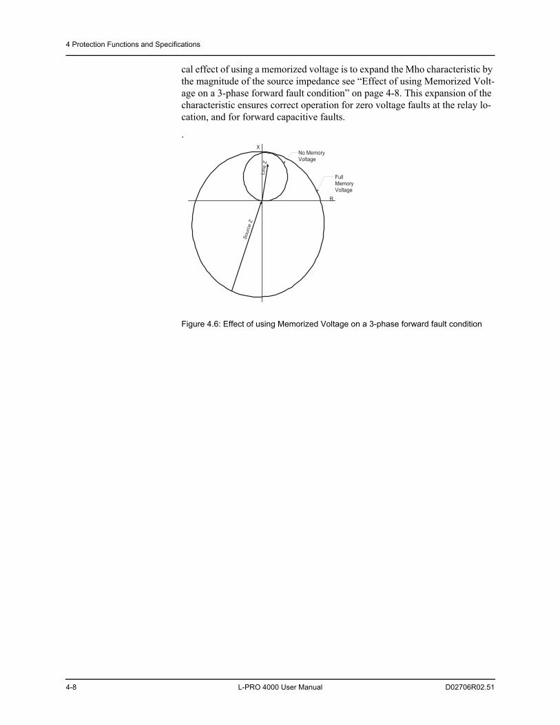
4-8 L-PRO 4000 User Manual D02706R02.51
cal effect of using a memorized voltage is to expand the Mho characteristic by the magnitude of the source impedance see “Effect of using Memorized Volt-age on a 3-phase forward fault condition” on page 4-8. This expansion of the characteristic ensures correct operation for zero voltage faults at the relay lo-cation, and for forward capacitive faults.
.
Figure 4.6: Effect of using Memorized Voltage on a 3-phase forward fault condition
R
X
Line
Z
Sou
rce
Z
No MemoryVoltage
FullMemoryVoltage
4 Protection Functions and Specifications
D02706R02.51 L-PRO 4000 User Manual 4-9
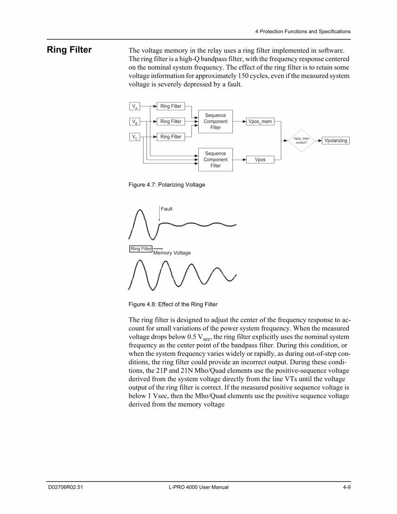
Ring Filter The voltage memory in the relay uses a ring filter implemented in software. The ring filter is a high-Q bandpass filter, with the frequency response centered on the nominal system frequency. The effect of the ring filter is to retain some voltage information for approximately 150 cycles, even if the measured system voltage is severely depressed by a fault.
Figure 4.7: Polarizing Voltage
Figure 4.8: Effect of the Ring Filter
The ring filter is designed to adjust the center of the frequency response to ac-count for small variations of the power system frequency. When the measured voltage drops below 0.5 Vsec, the ring filter explicitly uses the nominal system frequency as the center point of the bandpass filter. During this condition, or when the system frequency varies widely or rapidly, as during out-of-step con-ditions, the ring filter could provide an incorrect output. During these condi-tions, the 21P and 21N Mho/Quad elements use the positive-sequence voltage derived from the system voltage directly from the line VTs until the voltage output of the ring filter is correct. If the measured positive sequence voltage is below 1 Vsec, then the Mho/Quad elements use the positive sequence voltage derived from the memory voltage
VA Ring Filter
SequenceComponent
FilterVB
VC
Ring Filter
Ring Filter
Vpos_mem
SequenceComponent
FilterVpos
Vpos_memcorrect? Vpolarizing
Fault
Memory VoltageRing Filter
4 Protection Functions and Specifications
4-10 L-PRO 4000 User Manual D02706R02.51
Directional Element
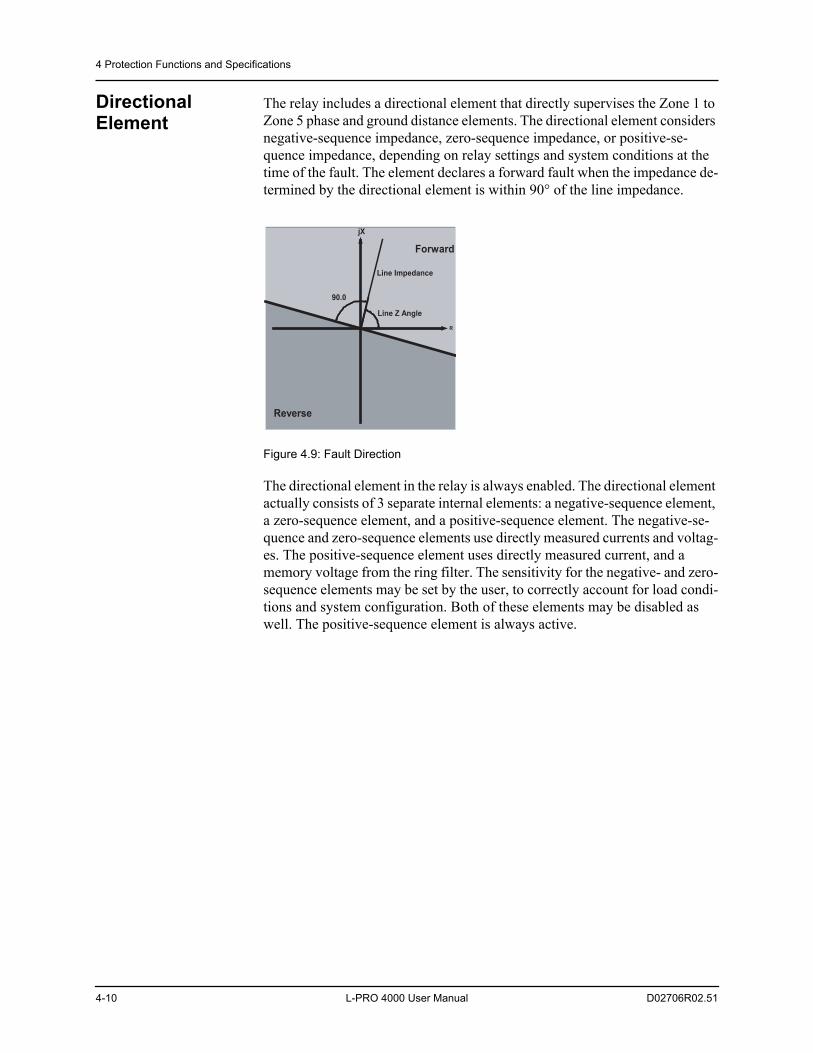
The relay includes a directional element that directly supervises the Zone 1 to Zone 5 phase and ground distance elements. The directional element considers negative-sequence impedance, zero-sequence impedance, or positive-se-quence impedance, depending on relay settings and system conditions at the time of the fault. The element declares a forward fault when the impedance de-termined by the directional element is within 90° of the line impedance.
Figure 4.9: Fault Direction
The directional element in the relay is always enabled. The directional element actually consists of 3 separate internal elements: a negative-sequence element, a zero-sequence element, and a positive-sequence element. The negative-se-quence and zero-sequence elements use directly measured currents and voltag-es. The positive-sequence element uses directly measured current, and a memory voltage from the ring filter. The sensitivity for the negative- and zero-sequence elements may be set by the user, to correctly account for load condi-tions and system configuration. Both of these elements may be disabled as well. The positive-sequence element is always active.
Reverse
Forward
Line Impedance
R
jX
90.0�
Line Z Angle
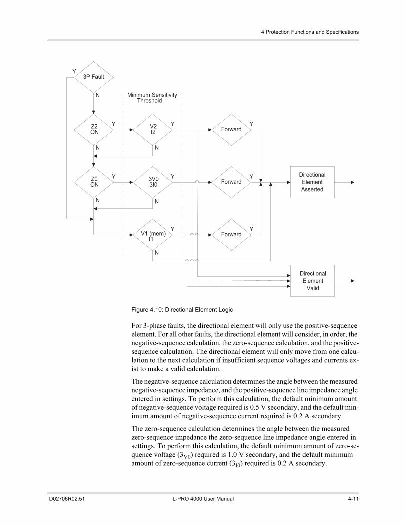
4 Protection Functions and Specifications
D02706R02.51 L-PRO 4000 User Manual 4-11
Figure 4.10: Directional Element Logic
For 3-phase faults, the directional element will only use the positive-sequence element. For all other faults, the directional element will consider, in order, the negative-sequence calculation, the zero-sequence calculation, and the positive-sequence calculation. The directional element will only move from one calcu-lation to the next calculation if insufficient sequence voltages and currents ex-ist to make a valid calculation.
The negative-sequence calculation determines the angle between the measured negative-sequence impedance, and the positive-sequence line impedance angle entered in settings. To perform this calculation, the default minimum amount of negative-sequence voltage required is 0.5 V secondary, and the default min-imum amount of negative-sequence current required is 0.2 A secondary.
The zero-sequence calculation determines the angle between the measured zero-sequence impedance the zero-sequence line impedance angle entered in settings. To perform this calculation, the default minimum amount of zero-se-quence voltage (3V0) required is 1.0 V secondary, and the default minimum amount of zero-sequence current (3I0) required is 0.2 A secondary.
3P Fault
Z2ON
Z0ON
V2I2
3V03I0
V1 (mem)I1
Forward
Forward
Forward
DirectionalElementAsserted
DirectionalElement
Valid
Y
Y
Y
Y
Y
Y
Y
Y
Y
N
N
N N
N
N
Minimum SensitivityThreshold
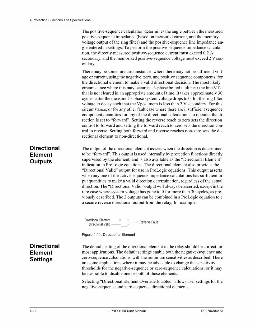
4 Protection Functions and Specifications
4-12 L-PRO 4000 User Manual D02706R02.51
The positive-sequence calculation determines the angle between the measured positive-sequence impedance (based on measured current, and the memory voltage output of the ring filter) and the positive-sequence line impedance an-gle entered in settings. To perform the positive-sequence impedance calcula-tion, the directly measured positive-sequence current must exceed 0.2 A secondary, and the memorized positive-sequence voltage must exceed 2 V sec-ondary.
There may be some rare circumstances where there may not be sufficient volt-age or current, using the negative, zero, and positive sequence components, for the directional element to make a valid directional decision. The most likely circumstance where this may occur is a 3-phase bolted fault near the line VTs, that is not cleared in an appropriate amount of time. It takes approximately 30 cycles, after the measured 3-phase system voltage drops to 0, for the ring filter voltage to decay such that the Vpos_mem is less than 2 V secondary. For this circumstance, or for any other fault case where there are insufficient sequence component quantities for any of the directional calculations to operate, the di-rection is set to “forward”. Setting the reverse reach to zero sets the direction control to forward and setting the forward reach to zero sets the direction con-trol to reverse. Setting both forward and reverse reaches non-zero sets the di-rectional element to non-directional.
Directional Element Outputs
The output of the directional element asserts when the direction is determined to be “forward”. This output is used internally by protection functions directly supervised by the element, and is also available as the “Directional Element” indication in ProLogic equations. The directional element also provides the “Directional Valid” output for use in ProLogic equations. This output asserts when any one of the active sequence impedance calculations has sufficient in-put quantities to make a valid direction determination, regardless of the actual direction. The “Directional Valid” output will always be asserted, except in the rare case where system voltage has gone to 0 for more than 30 cycles, as pre-viously described. The 2 outputs can be combined in a ProLogic equation to e a secure reverse directional output from the relay, for example.
Figure 4.11: Directional Element
Directional Element Settings
The default setting of the directional element in the relay should be correct for most applications. The default settings enable both the negative-sequence and zero-sequence calculations, with the minimum sensitivities as described. There are some applications where it may be advisable to change the sensitivity thresholds for the negative-sequence or zero-sequence calculations, or it may be desirable to disable one or both of these elements.
Selecting “Directional Element Override Enabled” allows user settings for the negative-sequence and zero-sequence directional elements.
Directional ElementDirectional Valid Reverse Fault
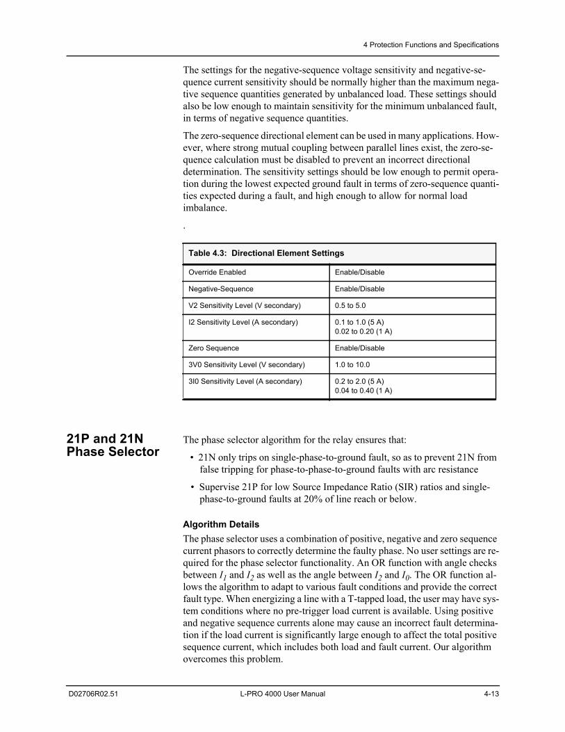
4 Protection Functions and Specifications
D02706R02.51 L-PRO 4000 User Manual 4-13
The settings for the negative-sequence voltage sensitivity and negative-se-quence current sensitivity should be normally higher than the maximum nega-tive sequence quantities generated by unbalanced load. These settings should also be low enough to maintain sensitivity for the minimum unbalanced fault, in terms of negative sequence quantities.
The zero-sequence directional element can be used in many applications. How-ever, where strong mutual coupling between parallel lines exist, the zero-se-quence calculation must be disabled to prevent an incorrect directional determination. The sensitivity settings should be low enough to permit opera-tion during the lowest expected ground fault in terms of zero-sequence quanti-ties expected during a fault, and high enough to allow for normal load imbalance.
.
21P and 21N Phase Selector
The phase selector algorithm for the relay ensures that:
• 21N only trips on single-phase-to-ground fault, so as to prevent 21N from false tripping for phase-to-phase-to-ground faults with arc resistance
• Supervise 21P for low Source Impedance Ratio (SIR) ratios and single-phase-to-ground faults at 20% of line reach or below.
Algorithm DetailsThe phase selector uses a combination of positive, negative and zero sequence current phasors to correctly determine the faulty phase. No user settings are re-quired for the phase selector functionality. An OR function with angle checks between I1 and I2 as well as the angle between I2 and I0. The OR function al-lows the algorithm to adapt to various fault conditions and provide the correct fault type. When energizing a line with a T-tapped load, the user may have sys-tem conditions where no pre-trigger load current is available. Using positive and negative sequence currents alone may cause an incorrect fault determina-tion if the load current is significantly large enough to affect the total positive sequence current, which includes both load and fault current. Our algorithm overcomes this problem.
Table 4.3: Directional Element Settings
Override Enabled Enable/Disable
Negative-Sequence Enable/Disable
V2 Sensitivity Level (V secondary) 0.5 to 5.0
I2 Sensitivity Level (A secondary) 0.1 to 1.0 (5 A)0.02 to 0.20 (1 A)
Zero Sequence Enable/Disable
3V0 Sensitivity Level (V secondary) 1.0 to 10.0
3I0 Sensitivity Level (A secondary) 0.2 to 2.0 (5 A)0.04 to 0.40 (1 A)
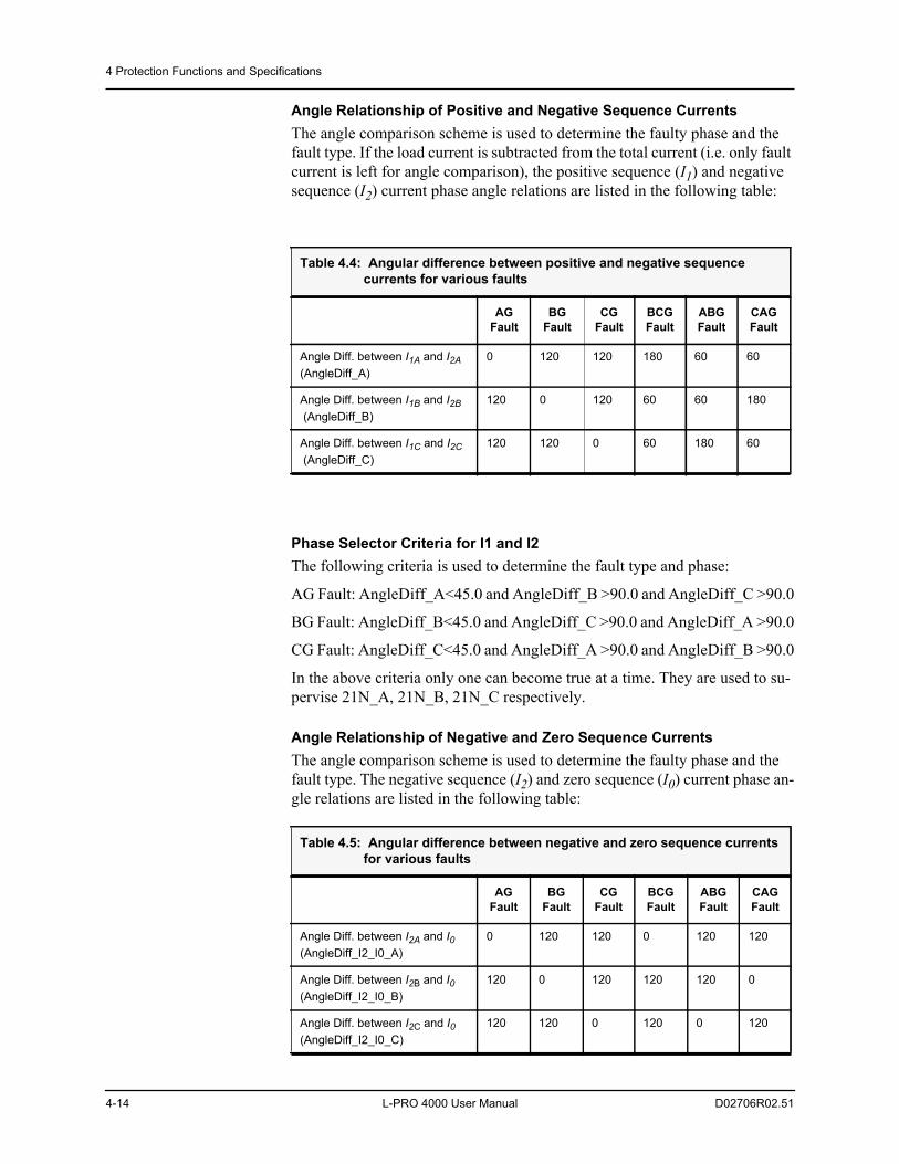
4 Protection Functions and Specifications
4-14 L-PRO 4000 User Manual D02706R02.51
Angle Relationship of Positive and Negative Sequence CurrentsThe angle comparison scheme is used to determine the faulty phase and the fault type. If the load current is subtracted from the total current (i.e. only fault current is left for angle comparison), the positive sequence (I1) and negative sequence (I2) current phase angle relations are listed in the following table:
Phase Selector Criteria for I1 and I2The following criteria is used to determine the fault type and phase:
AG Fault: AngleDiff_A<45.0 and AngleDiff_B >90.0 and AngleDiff_C >90.0
BG Fault: AngleDiff_B<45.0 and AngleDiff_C >90.0 and AngleDiff_A >90.0
CG Fault: AngleDiff_C<45.0 and AngleDiff_A >90.0 and AngleDiff_B >90.0
In the above criteria only one can become true at a time. They are used to su-pervise 21N_A, 21N_B, 21N_C respectively.
Angle Relationship of Negative and Zero Sequence CurrentsThe angle comparison scheme is used to determine the faulty phase and the fault type. The negative sequence (I2) and zero sequence (I0) current phase an-gle relations are listed in the following table:
Table 4.4: Angular difference between positive and negative sequence currents for various faults
AG Fault
BG Fault
CG Fault
BCG Fault
ABG Fault
CAG Fault
Angle Diff. between I1A and I2A (AngleDiff_A)
0 120 120 180 60 60
Angle Diff. between I1B and I2B (AngleDiff_B)
120 0 120 60 60 180
Angle Diff. between I1C and I2C (AngleDiff_C)
120 120 0 60 180 60
Table 4.5: Angular difference between negative and zero sequence currents for various faults
AG Fault
BG Fault
CG Fault
BCG Fault
ABG Fault
CAG Fault
Angle Diff. between I2A and I0(AngleDiff_I2_I0_A)
0 120 120 0 120 120
Angle Diff. between I2B and I0(AngleDiff_I2_I0_B)
120 0 120 120 120 0
Angle Diff. between I2C and I0(AngleDiff_I2_I0_C)
120 120 0 120 0 120
4 Protection Functions and Specifications
D02706R02.51 L-PRO 4000 User Manual 4-15
Phase Selector Criteria for I2 and I0The following criteria is used to determine the fault type and phase:
AG Fault: AngleDiff_I2_I0_A<25.0 degrees
BG Fault: AngleDiff_I2_I0_B<25.0 degrees
CG Fault: AngleDiff_I2_I0_C<25.0 degrees
Though AG type of fault will be declared for a BCG fault by the above angle criteria between I2 and I0, the characteristic of AG impedance prevents AG from tripping because the phase selector is used for supervision only, i.e. the phase selector is not a tripping device.
Device 21P SupervisionA 21P supervision logic is formed based on the above Phase Selector Criteria. The phase-to-phase distance element is only allowed to operate if the faulted phase is not involved with the element:
21P_AB Supervision = Not AG Fault and Not BG Fault
21P_BC Supervision = Not BG Fault and Not CG Fault
21P_CA Supervision = Not CG Fault and Not AG Fault
The Start of the Phase SelectorThe phase selector starts only when a fault occurs. The start definition is: if 3I0 is greater than the minimum of any enabled 21N zone’s 3I0 supervision level setting, begin the phase selector algorithm.
A buffer is used to track the pre-trigger load current, which is subtracted from the total current before checking the phase selector criteria.
During fault conditions the system frequency may change causing a drift in the angle difference being calculated by the phase selector. The locked pre-trigger load current vector is adjusted accordingly based on this angle difference be-tween the pre-trigger positive sequence voltage and the positive sequence volt-age during the fault. If the faulted positive sequence voltage shifts, the angle difference is taken into account. (i.e. the same angle relationship remains along the fault duration.)
Duration of the Phase Selector SupervisionThe maximum blocking time to 21N for a phase-phase-ground fault is from 2.0 seconds to x seconds, where x is the maximum pickup delay in enabled 21P2 to 21P5, and then plus 8 cycles (8 cycles is the maximum breaker opening).
This ensures that if 21P did not trip on the phase-phase-ground fault for some reason, 21N is allowed to trip on this fault after this maximum blocking time delay has expired.
4 Protection Functions and Specifications
4-16 L-PRO 4000 User Manual D02706R02.51
Ground Indicator in 21P Event Message3I0 is checked against the minimum of the following settings:
• 21N1: 3I0 supervision when it’s enabled
• 21N2: 3I0 supervision when it’s enabled
• 21N3: 3I0 supervision when it’s enabled
• 21N4: 3I0 supervision when it’s enabled
• 21N5: 3I0 supervision when its enabled
• 50N Pickup level when it’s enabled
• 51N Pickup level when it’s enabled
• 50N_67F when it’s selected as Scheme_Only or both ProLogic&Scheme
When 3I0 exceeds the minimum of the above values, a ground indicator “G” is put in the 21P event messages, e.g. “21P Trip ABG 123.1 km”.
Series Capacitor on 21 DevicesWhen a series capacitor is added to a transmission line, performance of 21 de-vices can be affected significantly due to the effects such as sub-harmonics, voltage inversion and current inversions. Series capacitor algorithm provides enhanced performances against the effect of series capacitors. The algorithm consists of two parts namely (i) sub-harmonic removal filter and (ii) modified directional function.
The sub-harmonic removal filter is a 5th order Infinite Impulse Response (IIR) filter. Upon enabling the series capacitor option, sub-harmonic removal filter will be activated.
Based on compensation factor settings (i.e. if compensation factor > 0), direc-tional function will be enabled. When the series capacitor is located at the end of the line, a compensation factor greater than zero should be used. In this case, voltage is measured from the line side PTs/CVTs. Reverse side voltage (esti-mated using line side voltage and phase currents) is used to determine the di-rectionality. When the series capacitor is located at the far end of the line or middle of the line, the compensation factor setting should be set to zero.
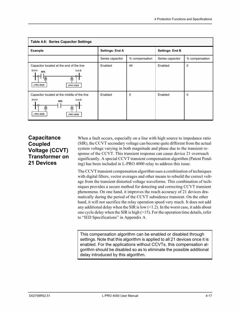
4 Protection Functions and Specifications
D02706R02.51 L-PRO 4000 User Manual 4-17
Capacitance Coupled Voltage (CCVT) Transformer on 21 Devices
When a fault occurs, especially on a line with high source to impedance ratio (SIR), the CCVT secondary voltage can become quite different from the actual system voltage varying in both magnitude and phase due to the transient re-sponse of the CCVT. This transient response can cause device 21 overreach significantly. A special CCVT transient compensation algorithm (Patent Pend-ing) has been included in L-PRO 4000 relay to address this issue.
The CCVT transient compensation algorithm uses a combination of techniques with digital filters, vector averages and other means to rebuild the correct volt-age from the transient distorted voltage waveforms. This combination of tech-niques provides a secure method for detecting and correcting CCVT transient phenomena. On one hand, it improves the reach accuracy of 21 devices dra-matically during the period of the CCVT subsidence transient. On the other hand, it will not sacrifice the relay operation speed very much. It does not add any additional delay when the SIR is low (<1.2). In the worst case, it adds about one cycle delay when the SIR is high (>15). For the operation time details, refer to “IED Specifications” in Appendix A.
Table 4.6: Series Capacitor Settings
Example Settings: End A Settings: End B
Series capacitor % compensation Series capacitor % compensation
Capacitor located at the end of the line Enabled 40 Enabled 0
Capacitor located at the middle of the line Enabled 0 Enabled 0
This compensation algorithm can be enabled or disabled through settings. Note that this algorithm is applied to all 21 devices once it is enabled. For the applications without CCVTs, this compensation al-gorithm should be disabled so as to eliminate the possible additional delay introduced by this algorithm.
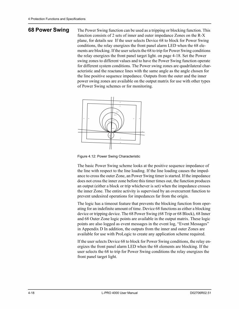
4 Protection Functions and Specifications
4-18 L-PRO 4000 User Manual D02706R02.51
68 Power Swing The Power Swing function can be used as a tripping or blocking function. This function consists of 2 sets of inner and outer impedance Zones on the R-X plane, for details see If the user selects Device 68 to block for Power Swing conditions, the relay energizes the front panel alarm LED when the 68 ele-ments are blocking. If the user selects the 68 to trip for Power Swing conditions the relay energizes the front panel target light. on page 4-18. Set the Power swing zones to different values and to have the Power Swing function operate for different system conditions. The Power swing zones are quadrilateral char-acteristic and the reactance lines with the same angle as the angle chosen for the line positive sequence impedance. Outputs from the outer and the inner power swing zones are available on the output matrix for use with other types of Power Swing schemes or for monitoring.
Figure 4.12: Power Swing Characteristic
The basic Power Swing scheme looks at the positive sequence impedance of the line with respect to the line loading. If the line loading causes the imped-ance to cross the outer Zone, an Power Swing timer is started. If the impedance does not cross the inner zone before this timer times out, the function produces an output (either a block or trip whichever is set) when the impedance crosses the inner Zone. The entire activity is supervised by an overcurrent function to prevent undesired operations for impedances far from the origin.
The logic has a timeout feature that prevents the blocking function from oper-ating for an indefinite amount of time. Device 68 functions as either a blocking device or tripping device. The 68 Power Swing (68 Trip or 68 Block), 68 Inner and 68 Outer Zone logic points are available in the output matrix. These logic points are also logged as event messages in the event log, “Event Messages” in Appendix D In addition, the outputs from the inner and outer Zones are available for use with ProLogic to create any application scheme required.
If the user selects Device 68 to block for Power Swing conditions, the relay en-ergizes the front panel alarm LED when the 68 elements are blocking. If the user selects the 68 to trip for Power Swing conditions the relay energizes the front panel target light.
Zone 5
Zone 3
Zone 2
Zone 1
Zone 4
Line Z1
Line AngleR
X
X3
X4
X2
X1
R4R3R2R1
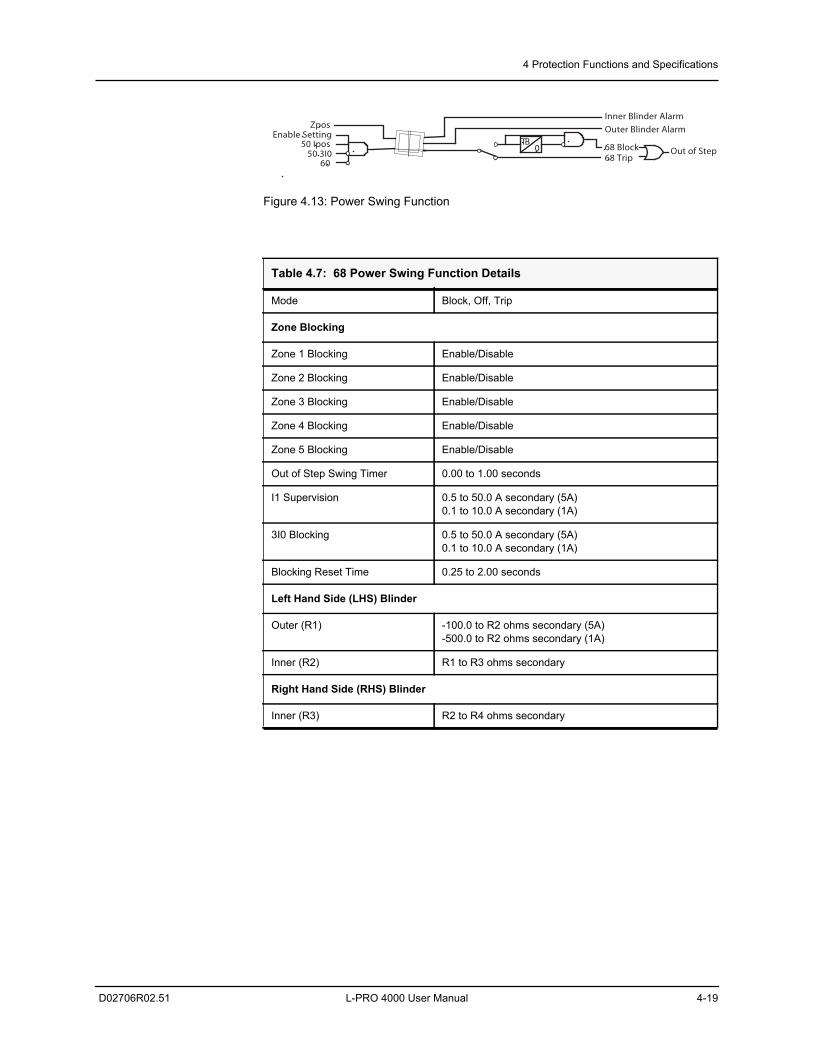
4 Protection Functions and Specifications
D02706R02.51 L-PRO 4000 User Manual 4-19
Figure 4.13: Power Swing Function
Table 4.7: 68 Power Swing Function Details
Mode Block, Off, Trip
Zone Blocking
Zone 1 Blocking Enable/Disable
Zone 2 Blocking Enable/Disable
Zone 3 Blocking Enable/Disable
Zone 4 Blocking Enable/Disable
Zone 5 Blocking Enable/Disable
Out of Step Swing Timer 0.00 to 1.00 seconds
I1 Supervision 0.5 to 50.0 A secondary (5A)0.1 to 10.0 A secondary (1A)
3I0 Blocking 0.5 to 50.0 A secondary (5A)0.1 to 10.0 A secondary (1A)
Blocking Reset Time 0.25 to 2.00 seconds
Left Hand Side (LHS) Blinder
Outer (R1) -100.0 to R2 ohms secondary (5A)-500.0 to R2 ohms secondary (1A)
Inner (R2) R1 to R3 ohms secondary
Right Hand Side (RHS) Blinder
Inner (R3) R2 to R4 ohms secondary
Enable Setting 50 Ipos
60 50 3I0
Zpos
TB0
68 Trip 68 Block
Inner Blinder Alarm
Outer Blinder Alarm
Out of Step
X
R
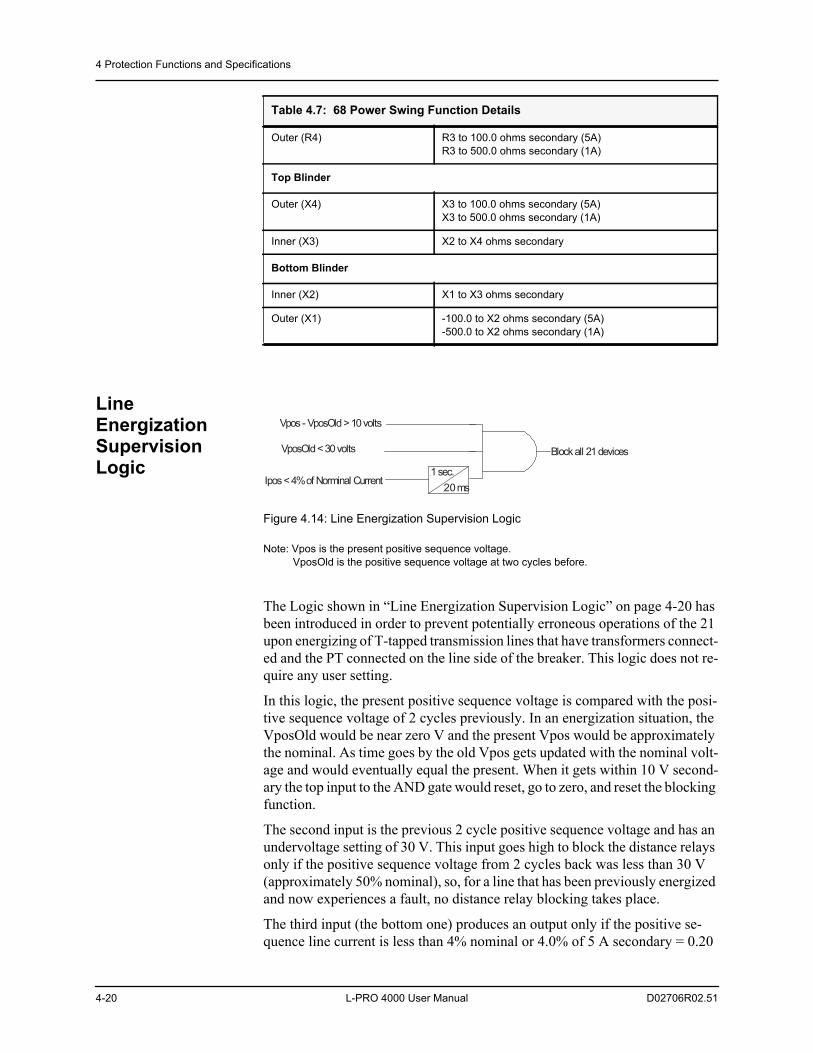
4 Protection Functions and Specifications
4-20 L-PRO 4000 User Manual D02706R02.51
Line Energization Supervision Logic
Figure 4.14: Line Energization Supervision Logic
Note: Vpos is the present positive sequence voltage. VposOld is the positive sequence voltage at two cycles before.
The Logic shown in “Line Energization Supervision Logic” on page 4-20 has been introduced in order to prevent potentially erroneous operations of the 21 upon energizing of T-tapped transmission lines that have transformers connect-ed and the PT connected on the line side of the breaker. This logic does not re-quire any user setting.
In this logic, the present positive sequence voltage is compared with the posi-tive sequence voltage of 2 cycles previously. In an energization situation, the VposOld would be near zero V and the present Vpos would be approximately the nominal. As time goes by the old Vpos gets updated with the nominal volt-age and would eventually equal the present. When it gets within 10 V second-ary the top input to the AND gate would reset, go to zero, and reset the blocking function.
The second input is the previous 2 cycle positive sequence voltage and has an undervoltage setting of 30 V. This input goes high to block the distance relays only if the positive sequence voltage from 2 cycles back was less than 30 V (approximately 50% nominal), so, for a line that has been previously energized and now experiences a fault, no distance relay blocking takes place.
The third input (the bottom one) produces an output only if the positive se-quence line current is less than 4% nominal or 4.0% of 5 A secondary = 0.20
Outer (R4) R3 to 100.0 ohms secondary (5A)R3 to 500.0 ohms secondary (1A)
Top Blinder
Outer (X4) X3 to 100.0 ohms secondary (5A)X3 to 500.0 ohms secondary (1A)
Inner (X3) X2 to X4 ohms secondary
Bottom Blinder
Inner (X2) X1 to X3 ohms secondary
Outer (X1) -100.0 to X2 ohms secondary (5A)-500.0 to X2 ohms secondary (1A)
Table 4.7: 68 Power Swing Function Details
Vpos - VposOld > 10 volts
1 sec.20 ms
VposOld < 30 volts
Ipos < 4% of Norminal Current
Block all 21 devices
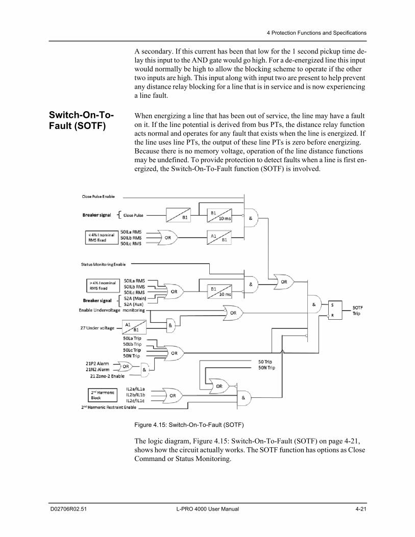
4 Protection Functions and Specifications
D02706R02.51 L-PRO 4000 User Manual 4-21
A secondary. If this current has been that low for the 1 second pickup time de-lay this input to the AND gate would go high. For a de-energized line this input would normally be high to allow the blocking scheme to operate if the other two inputs are high. This input along with input two are present to help prevent any distance relay blocking for a line that is in service and is now experiencing a line fault.
Switch-On-To-Fault (SOTF)
When energizing a line that has been out of service, the line may have a fault on it. If the line potential is derived from bus PTs, the distance relay function acts normal and operates for any fault that exists when the line is energized. If the line uses line PTs, the output of these line PTs is zero before energizing. Because there is no memory voltage, operation of the line distance functions may be undefined. To provide protection to detect faults when a line is first en-ergized, the Switch-On-To-Fault function (SOTF) is involved.
Figure 4.15: Switch-On-To-Fault (SOTF)
The logic diagram, Figure 4.15: Switch-On-To-Fault (SOTF) on page 4-21, shows how the circuit actually works. The SOTF function has options as Close Command or Status Monitoring.
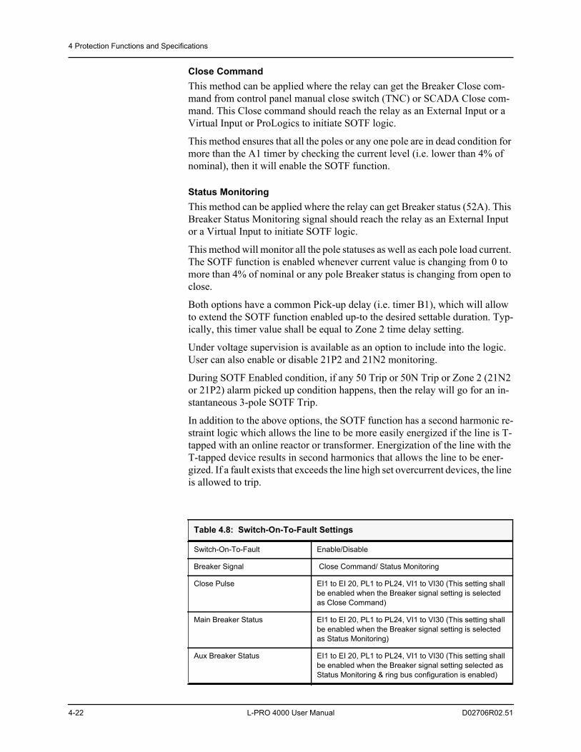
4 Protection Functions and Specifications
4-22 L-PRO 4000 User Manual D02706R02.51
Close CommandThis method can be applied where the relay can get the Breaker Close com-mand from control panel manual close switch (TNC) or SCADA Close com-mand. This Close command should reach the relay as an External Input or a Virtual Input or ProLogics to initiate SOTF logic.
This method ensures that all the poles or any one pole are in dead condition for more than the A1 timer by checking the current level (i.e. lower than 4% of nominal), then it will enable the SOTF function.
Status MonitoringThis method can be applied where the relay can get Breaker status (52A). This Breaker Status Monitoring signal should reach the relay as an External Input or a Virtual Input to initiate SOTF logic.
This method will monitor all the pole statuses as well as each pole load current. The SOTF function is enabled whenever current value is changing from 0 to more than 4% of nominal or any pole Breaker status is changing from open to close.
Both options have a common Pick-up delay (i.e. timer B1), which will allow to extend the SOTF function enabled up-to the desired settable duration. Typ-ically, this timer value shall be equal to Zone 2 time delay setting.
Under voltage supervision is available as an option to include into the logic. User can also enable or disable 21P2 and 21N2 monitoring.
During SOTF Enabled condition, if any 50 Trip or 50N Trip or Zone 2 (21N2 or 21P2) alarm picked up condition happens, then the relay will go for an in-stantaneous 3-pole SOTF Trip.
In addition to the above options, the SOTF function has a second harmonic re-straint logic which allows the line to be more easily energized if the line is T-tapped with an online reactor or transformer. Energization of the line with the T-tapped device results in second harmonics that allows the line to be ener-gized. If a fault exists that exceeds the line high set overcurrent devices, the line is allowed to trip.
Table 4.8: Switch-On-To-Fault Settings
Switch-On-To-Fault Enable/Disable
Breaker Signal Close Command/ Status Monitoring
Close Pulse EI1 to EI 20, PL1 to PL24, VI1 to VI30 (This setting shall be enabled when the Breaker signal setting is selected as Close Command)
Main Breaker Status EI1 to EI 20, PL1 to PL24, VI1 to VI30 (This setting shall be enabled when the Breaker signal setting is selected as Status Monitoring)
Aux Breaker Status EI1 to EI 20, PL1 to PL24, VI1 to VI30 (This setting shall be enabled when the Breaker signal setting selected as Status Monitoring & ring bus configuration is enabled)
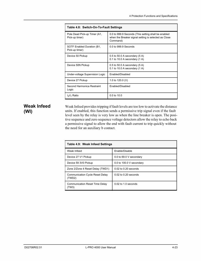
4 Protection Functions and Specifications
D02706R02.51 L-PRO 4000 User Manual 4-23
Weak Infeed (WI)
Weak Infeed provides tripping if fault levels are too low to activate the distance units. If enabled, this function sends a permissive trip signal even if the fault level seen by the relay is very low as when the line breaker is open. The posi-tive sequence and zero sequence voltage detectors allow the relay to echo back a permissive signal to allow the end with fault current to trip quickly without the need for an auxiliary b contact.
Pole Dead Pick-up Timer (A1, Pick-up timer)
0.0 to 999.9 Seconds (This setting shall be enabled when the Breaker signal setting is selected as Close Command)
SOTF Enabled Duration (B1, Pick-up timer)
0.0 to 999.9 Seconds
Device 50 Pickup 0.5 to 50.0 A secondary (5 A)0.1 to 10.0 A secondary (1 A)
Device 50N Pickup 0.5 to 50.0 A secondary (5 A)0.1 to 10.0 A secondary (1 A)
Under-voltage Supervision Logic Enabled/Disabled
Device 27 Pickup 1.0 to 120.0 (V)
Second Harmonica Restraint Logic
Enabled/Disabled
I2/I1 Ratio 0.0 to 10.0
Table 4.8: Switch-On-To-Fault Settings
Table 4.9: Weak Infeed Settings
Weak Infeed Enable/Disable
Device 27 V1 Pickup 0.0 to 69.0 V secondary
Device 59 3V0 Pickup 0.0 to 100.0 V secondary
Zone 2/Zone 4 Reset Delay (TWD1) 0.02 to 0.20 seconds
Communication Cycle Reset Delay (TWD2)
0.02 to 0.20 seconds
Communication Reset Time Delay (TW3)
0.02 to 1.0 seconds
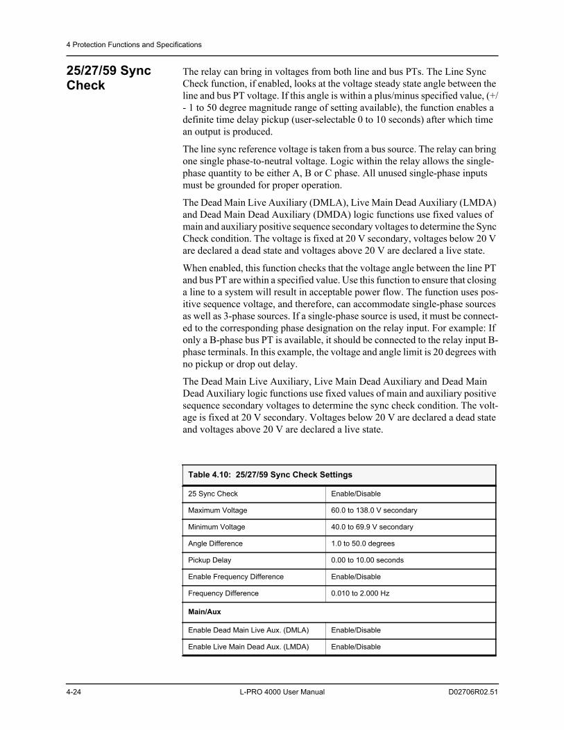
4 Protection Functions and Specifications
4-24 L-PRO 4000 User Manual D02706R02.51
25/27/59 Sync Check
The relay can bring in voltages from both line and bus PTs. The Line Sync Check function, if enabled, looks at the voltage steady state angle between the line and bus PT voltage. If this angle is within a plus/minus specified value, (+/- 1 to 50 degree magnitude range of setting available), the function enables a definite time delay pickup (user-selectable 0 to 10 seconds) after which time an output is produced.
The line sync reference voltage is taken from a bus source. The relay can bring one single phase-to-neutral voltage. Logic within the relay allows the single-phase quantity to be either A, B or C phase. All unused single-phase inputs must be grounded for proper operation.
The Dead Main Live Auxiliary (DMLA), Live Main Dead Auxiliary (LMDA) and Dead Main Dead Auxiliary (DMDA) logic functions use fixed values of main and auxiliary positive sequence secondary voltages to determine the Sync Check condition. The voltage is fixed at 20 V secondary, voltages below 20 V are declared a dead state and voltages above 20 V are declared a live state.
When enabled, this function checks that the voltage angle between the line PT and bus PT are within a specified value. Use this function to ensure that closing a line to a system will result in acceptable power flow. The function uses pos-itive sequence voltage, and therefore, can accommodate single-phase sources as well as 3-phase sources. If a single-phase source is used, it must be connect-ed to the corresponding phase designation on the relay input. For example: If only a B-phase bus PT is available, it should be connected to the relay input B-phase terminals. In this example, the voltage and angle limit is 20 degrees with no pickup or drop out delay.
The Dead Main Live Auxiliary, Live Main Dead Auxiliary and Dead Main Dead Auxiliary logic functions use fixed values of main and auxiliary positive sequence secondary voltages to determine the sync check condition. The volt-age is fixed at 20 V secondary. Voltages below 20 V are declared a dead state and voltages above 20 V are declared a live state.
Table 4.10: 25/27/59 Sync Check Settings
25 Sync Check Enable/Disable
Maximum Voltage 60.0 to 138.0 V secondary
Minimum Voltage 40.0 to 69.9 V secondary
Angle Difference 1.0 to 50.0 degrees
Pickup Delay 0.00 to 10.00 seconds
Enable Frequency Difference Enable/Disable
Frequency Difference 0.010 to 2.000 Hz
Main/Aux
Enable Dead Main Live Aux. (DMLA) Enable/Disable
Enable Live Main Dead Aux. (LMDA) Enable/Disable
4 Protection Functions and Specifications
D02706R02.51 L-PRO 4000 User Manual 4-25
79 Recloser The relay provides single-phase tripping and reclosing and 3-phase tripping and reclosing on the 4000 hardware platform.
The schemes available are user-programmable and consist of the following user setting options:
• 3-Phase Trip and Reclose Scheme
• 1-Phase/3-Phase Trip and Reclose Scheme
Please note that the user can select only one scheme at a time, although the user can change the scheme selected by using the setting groups within the setting software.
3-Phase Trip and Reclose SchemeThis scheme allows the relay to 3 phase trip always (even if the fault is single phase in nature) and reclose the 3 phases after a period of time. Up to 4 shots of reclosing is possible, depending upon the user recloser settings. The recloser logic control is capable of reclosing a single line breaker or two ring bus line breakers in a variety of sequences. The breaker reclosing sequence refers to the breakers as lead and follower breakers. The first breaker selected to reclose is called the lead breaker and the second breaker that is reclosed is called the fol-lower. The reclosing can be done with or without synch check supervision. The output matrix is used to determine the inputs and the outputs to the 3-phase 79 recloser. The line breaker (s) is deemed to be open if the current through it is below 4% of the nominal current rating. (For a 5 A rated relay, this is 0.2 A rms)
3-Phase Reclose TimersThe lead breaker open interval times are settable for each reclosing shot (T1 to T4) for the 3-phase recloser. The follow breaker open time interval is common for each reclosure attempt. This follower breaker reclose time can be set to use the 79 follower timer TF or the 79 reset timer TD. See L-PRO 4000 Function Logic Diagram for details.
Lead or Follower Breaker Logic The recloser setting options allow the lead breaker to be the main or auxiliary breaker. The recloser automatically selects the follower breaker into the lead position after the out of service time delay, TC is exceeded. If the follower breaker is removed from service, after the out of service time delay, TC, there is no further follower breaker reclose attempts. The breaker status is reset when the breaker status changes to closed for at least 10 seconds, or if the relay pow-er supply is toggled Off then On again. A breaker is considered to be closed if
Enable Dead Main Dead Aux. (DMDA) Enable/Disable
Table 4.10: 25/27/59 Sync Check Settings
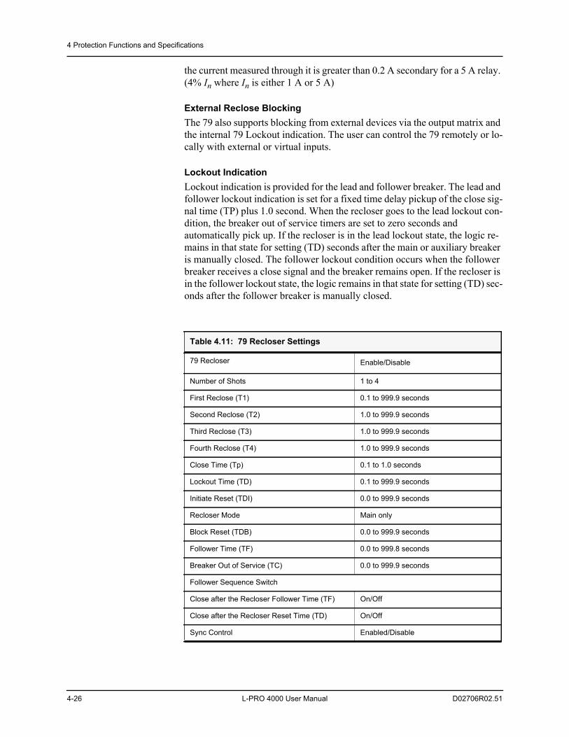
4 Protection Functions and Specifications
4-26 L-PRO 4000 User Manual D02706R02.51
the current measured through it is greater than 0.2 A secondary for a 5 A relay. (4% In where In is either 1 A or 5 A)
External Reclose BlockingThe 79 also supports blocking from external devices via the output matrix and the internal 79 Lockout indication. The user can control the 79 remotely or lo-cally with external or virtual inputs.
Lockout IndicationLockout indication is provided for the lead and follower breaker. The lead and follower lockout indication is set for a fixed time delay pickup of the close sig-nal time (TP) plus 1.0 second. When the recloser goes to the lead lockout con-dition, the breaker out of service timers are set to zero seconds and automatically pick up. If the recloser is in the lead lockout state, the logic re-mains in that state for setting (TD) seconds after the main or auxiliary breaker is manually closed. The follower lockout condition occurs when the follower breaker receives a close signal and the breaker remains open. If the recloser is in the follower lockout state, the logic remains in that state for setting (TD) sec-onds after the follower breaker is manually closed.
Table 4.11: 79 Recloser Settings
79 Recloser Enable/Disable
Number of Shots 1 to 4
First Reclose (T1) 0.1 to 999.9 seconds
Second Reclose (T2) 1.0 to 999.9 seconds
Third Reclose (T3) 1.0 to 999.9 seconds
Fourth Reclose (T4) 1.0 to 999.9 seconds
Close Time (Tp) 0.1 to 1.0 seconds
Lockout Time (TD) 0.1 to 999.9 seconds
Initiate Reset (TDI) 0.0 to 999.9 seconds
Recloser Mode Main only
Block Reset (TDB) 0.0 to 999.9 seconds
Follower Time (TF) 0.0 to 999.8 seconds
Breaker Out of Service (TC) 0.0 to 999.9 seconds
Follower Sequence Switch
Close after the Recloser Follower Time (TF) On/Off
Close after the Recloser Reset Time (TD) On/Off
Sync Control Enabled/Disable
4 Protection Functions and Specifications
D02706R02.51 L-PRO 4000 User Manual 4-27
The recloser provides flexibility with lead and follower breaker options. The lead breaker is in the main or auxiliary position. This allows the user to control the lead circuit breaker with complete Dead Main Live Auxiliary, Live Main Dead Auxiliary, Dead Main Dead Auxiliary or Live Main Live Auxiliary su-pervision (angle limit and voltage limit). The user also has the ability to control the 79 remotely or locally with external or virtual inputs. The 79 recloser mon-itors the breaker contact “a” status and automatically moves the follower breaker into the lead position when the lead breaker is removed from service, after an out-of-service time delay setting. For details of auto-recloser examples see “L-PRO Setting Example” in Appendix L.
Sync ControlThe flexibility provided with device 79 allows the user to control 1 or 2 circuit breakers with complete Dead Main Live Auxiliary, Live Main Dead Auxiliary, Dead Main Dead Auxiliary or Live Main Live Auxiliary supervision (slip fre-quency). Sync control is provided on the lead breaker only, because the follow-er breaker always recloses after the lead breaker has successfully closed. ProLogic can be used to supervise follower breaker closing attempts if an ex-ternal input is used to signal that the follower breaker has a valid sync check signal from an external device (e.g. PLC).
Operation of the Relay with the Single-Phase Trip and Reclose Scheme SettingThis setting allows the relay to trip only the faulted phase if the fault is single phase in nature, then initiate a reclose of that phase after a line dead time. The reason for this is that many faults are transient in nature, such as those caused by lightening. The trip of the faulted phase, and that the trip of the faulted phase then reclosing it some time later, should in many cases allow the line to return into service. The benefit of this scheme is that approximately one half of the power flow on the line (before the fault occurs) can be sent down the line dur-ing the open phase condition, promoting system stability and eliminating the need to resynchronize the line.
It should be noted that employing this scheme means that the high voltage line breakers must be capable of opening and reclosing in a single phase mode and that additional equipment such as line and neutral reactors must be installed on the line in order to allow the scheme to work correctly. A thorough systems study on the line and surrounding equipment must be performed in order that appropriate scheme settings be determined to obtain satisfactory performance of this scheme.
In operation, the Single-Phase Trip Setting blocks 79-3 from any attempts to reclose on a 3 Phase basis. If a single phase fault occurs on the line, the faulted phase is identified and only that phase is opened. After a period of time as de-fined by the pickup time of timer T1 in the single phase recloser 79-1, that phase will be reclosed. If the fault starts as a single phase fault and then evolves into a multiphase fault, or commutates to a different phase while the first phase is open, the line will 3 phase trip and reclosing will be inhibited. If the first sin-gle phase fault is detected, then reclosed upon, and if the fault persists, the line will 3-phase trip and lockout. Timer TD5 dropout time determines how soon a
4 Protection Functions and Specifications
4-28 L-PRO 4000 User Manual D02706R02.51
subsequent single line to ground fault can occur after the first one in order for the line to attempt another single phase trip and reclosure. If a single phase fault is detected and that phase opens but fails to reclose before timer TM times out, the line will 3-phase trip and lockout. It is important therefore that timer TM be set longer in duration than the single phase recloser time. Only one sin-gle phase reclose is attempted. If upon reclosure the fault persists, before timer TD5 has had a chance to dropout, the line will 3-phase trip and lockout. To get the line out of a locked out state, the line must be manually reclosed and stay in service for longer than the single phase lockout timer TD reset.
Protection functions that can initiate a single phase trip and reclose are defined by the user in the output matrix setting screen. The user has full control to dic-tate which protection functions should initiate the recloser logic. Time delayed trips for instance may be considered backup functions where recloser initiation is undesired. In this case these types of operations can be set to block any at-tempted reclosures in any of the chosen reclosure schemes. These protection functions can also be set to initiate transient fault or dynamic swing recordings and breaker failure initiations on the output matrix as well.
During the single pole open condition while in the single pole tripping mode, unbalanced line load current will create negative and zero sequence line quan-tities. In order to override these unbalances, provisions have been made in the relay logic to allow the user to apply modified protective relay settings to the line protections that will be automatically applied while the line is in a phase open condition. These settings can be determined through load flow and fault study cases for the protected line. Once the line phase recloses, the protective settings that have been modified will return to their original settings. In this way, protection security can be maintained while the line goes through a single phase trip and reclose operation.
The drawing for the single phase reclosing logic is shown on the L-PRO 4000 Function Logic Diagram.
Single-Phase/3-Phase Trip and Reclose Scheme With this scheme setting, the relay will trip and reclose a single phase for an initial Single Phase fault and will trip and reclose for a Three Phase or multi-phase fault. Only one attempt to reclose will occur if the fault is permanent in nature before lockout will occur.
If sufficient time takes place between the first fault and subsequent new line faults, as determined by the TD4 and TD5 dropout times, the protection will try to keep the line in service by tripping and reclosing the line as required.
It should be noted that the relay has two types of reclosers, a single phase type 79-1 and a 3-phase type 79-3 recloser.
The single phase recloser has only one shot, determined by timer T1. This time delay applies for both the Single Phase Scheme and for the Single Phase/Three Phase Scheme settings.
The 3-phase recloser has a common setting for the first reclose of the Three Phase or the Single Phase/Three Phase Trip and Reclose Schemes.
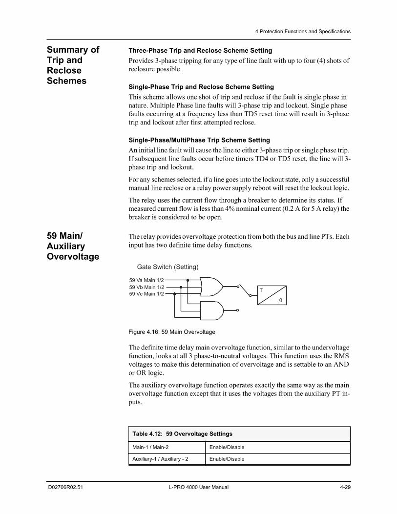
4 Protection Functions and Specifications
D02706R02.51 L-PRO 4000 User Manual 4-29
Summary of Trip and Reclose Schemes
Three-Phase Trip and Reclose Scheme Setting Provides 3-phase tripping for any type of line fault with up to four (4) shots of reclosure possible.
Single-Phase Trip and Reclose Scheme SettingThis scheme allows one shot of trip and reclose if the fault is single phase in nature. Multiple Phase line faults will 3-phase trip and lockout. Single phase faults occurring at a frequency less than TD5 reset time will result in 3-phase trip and lockout after first attempted reclose.
Single-Phase/MultiPhase Trip Scheme SettingAn initial line fault will cause the line to either 3-phase trip or single phase trip. If subsequent line faults occur before timers TD4 or TD5 reset, the line will 3-phase trip and lockout.
For any schemes selected, if a line goes into the lockout state, only a successful manual line reclose or a relay power supply reboot will reset the lockout logic.
The relay uses the current flow through a breaker to determine its status. If measured current flow is less than 4% nominal current (0.2 A for 5 A relay) the breaker is considered to be open.
59 Main/Auxiliary Overvoltage
The relay provides overvoltage protection from both the bus and line PTs. Each input has two definite time delay functions.
Figure 4.16: 59 Main Overvoltage
The definite time delay main overvoltage function, similar to the undervoltage function, looks at all 3 phase-to-neutral voltages. This function uses the RMS voltages to make this determination of overvoltage and is settable to an AND or OR logic.
The auxiliary overvoltage function operates exactly the same way as the main overvoltage function except that it uses the voltages from the auxiliary PT in-puts.
Table 4.12: 59 Overvoltage Settings
Main-1 / Main-2 Enable/Disable
Auxiliary-1 / Auxiliary - 2 Enable/Disable
59 Va Main 1/2
59 Vb Main 1/2
59 Vc Main 1/2T
0
Gate Switch (Setting)
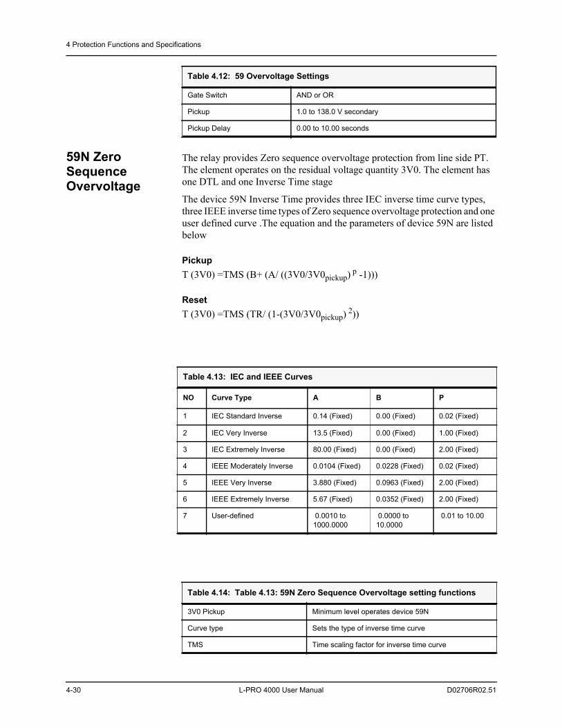
4 Protection Functions and Specifications
4-30 L-PRO 4000 User Manual D02706R02.51
59N Zero Sequence Overvoltage
The relay provides Zero sequence overvoltage protection from line side PT. The element operates on the residual voltage quantity 3V0. The element has one DTL and one Inverse Time stage
The device 59N Inverse Time provides three IEC inverse time curve types, three IEEE inverse time types of Zero sequence overvoltage protection and one user defined curve .The equation and the parameters of device 59N are listed below
PickupT (3V0) =TMS (B+ (A/ ((3V0/3V0pickup) p -1)))
ResetT (3V0) =TMS (TR/ (1-(3V0/3V0pickup) 2))
Gate Switch AND or OR
Pickup 1.0 to 138.0 V secondary
Pickup Delay 0.00 to 10.00 seconds
Table 4.12: 59 Overvoltage Settings
Table 4.13: IEC and IEEE Curves
NO Curve Type A B P
1 IEC Standard Inverse 0.14 (Fixed) 0.00 (Fixed) 0.02 (Fixed)
2 IEC Very Inverse 13.5 (Fixed) 0.00 (Fixed) 1.00 (Fixed)
3 IEC Extremely Inverse 80.00 (Fixed) 0.00 (Fixed) 2.00 (Fixed)
4 IEEE Moderately Inverse 0.0104 (Fixed) 0.0228 (Fixed) 0.02 (Fixed)
5 IEEE Very Inverse 3.880 (Fixed) 0.0963 (Fixed) 2.00 (Fixed)
6 IEEE Extremely Inverse 5.67 (Fixed) 0.0352 (Fixed) 2.00 (Fixed)
7 User-defined 0.0010 to 1000.0000
0.0000 to 10.0000
0.01 to 10.00
Table 4.14: Table 4.13: 59N Zero Sequence Overvoltage setting functions
3V0 Pickup Minimum level operates device 59N
Curve type Sets the type of inverse time curve
TMS Time scaling factor for inverse time curve
4 Protection Functions and Specifications
D02706R02.51 L-PRO 4000 User Manual 4-31
A, B, p Parameters for defining the curve
TR Factor for altering the reset time
Table 4.15: 59N Zero sequence overvoltage setting ranges
59N Inverse Time Delay Enable/Disable
Pickup (Volt) 5.00 to 150.00
Curve Type See Table 4.12: IEC and IEEE curves
TMS 0.01 to 10.00
A 0.0010 to 1000.0
B 0.0000 to 10.0
p 0.01 to 10.0
TR 0.10 to 100.0
59N Definite Time Delay Enable/Disable
Pickup (Volt) 5.00 to 150.00
Pickup Delay (Sec) 0.00 to 99.99
Table 4.14: Table 4.13: 59N Zero Sequence Overvoltage setting functions
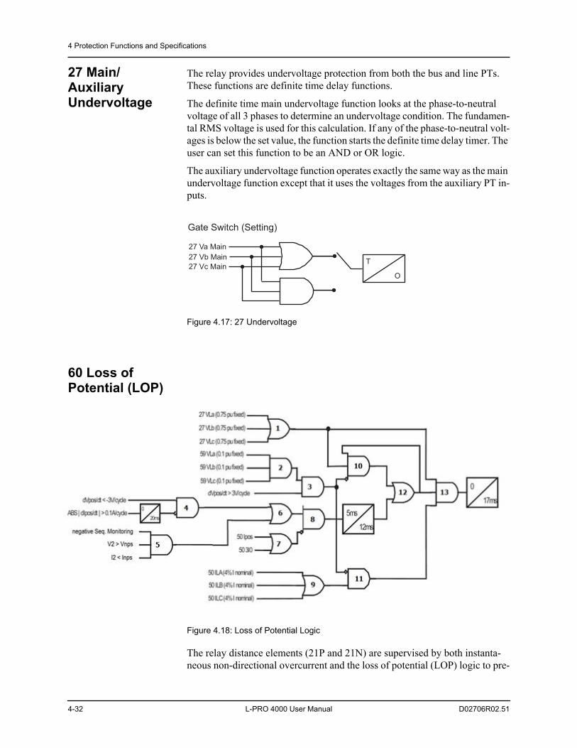
4 Protection Functions and Specifications
4-32 L-PRO 4000 User Manual D02706R02.51
27 Main/Auxiliary Undervoltage
The relay provides undervoltage protection from both the bus and line PTs. These functions are definite time delay functions.
The definite time main undervoltage function looks at the phase-to-neutral voltage of all 3 phases to determine an undervoltage condition. The fundamen-tal RMS voltage is used for this calculation. If any of the phase-to-neutral volt-ages is below the set value, the function starts the definite time delay timer. The user can set this function to be an AND or OR logic.
The auxiliary undervoltage function operates exactly the same way as the main undervoltage function except that it uses the voltages from the auxiliary PT in-puts.
Figure 4.17: 27 Undervoltage
60 Loss of Potential (LOP)
Figure 4.18: Loss of Potential Logic
The relay distance elements (21P and 21N) are supervised by both instanta-neous non-directional overcurrent and the loss of potential (LOP) logic to pre-
27 Va Main
27 Vb Main
27 Vc MainT
O
Gate Switch (Setting)
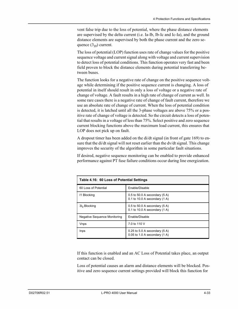
4 Protection Functions and Specifications
D02706R02.51 L-PRO 4000 User Manual 4-33
vent false trip due to the loss of potential, where the phase distance elements are supervised by the delta current (i.e. Ia-Ib, Ib-Ic and Ic-Ia), and the ground distance elements are supervised by both the phase current and the zero se-quence (3I0) current.
The loss of potential (LOP) function uses rate of change values for the positive sequence voltage and current signal along with voltage and current supervision to detect loss of potential conditions. This function operates very fast and been field proven to block the distance elements during potential transferring be-tween buses.
The function looks for a negative rate of change on the positive sequence volt-age while determining if the positive sequence current is changing. A loss of potential in itself should result in only a loss of voltage or a negative rate of change of voltage. A fault results in a high rate of change of current as well. In some rare cases there is a negative rate of change of fault current, therefore we use an absolute rate of change of current. When the loss of potential condition is detected, it is latched until all the 3-phase voltages are above 75% or a pos-itive rate of change of voltage is detected. So the circuit detects a loss of poten-tial that results in a voltage of less than 75%. Select positive and zero sequence current blocking functions above the maximum load current, this ensures that LOP does not pick up on fault.
A dropout timer has been added on the di/dt signal (in front of gate 169) to en-sure that the di/dt signal will not reset earlier than the dv/dt signal. This change improves the security of the algorithm in some particular fault situations.
If desired, negative sequence monitoring can be enabled to provide enhanced performance against PT fuse failure conditions occur during line energization.
If this function is enabled and an AC Loss of Potential takes place, an output contact can be closed.
Loss of potential causes an alarm and distance elements will be blocked. Pos-itive and zero sequence current settings provided will block this function for
Table 4.16: 60 Loss of Potential Settings
60 Loss of Potential Enable/Disable
I1 Blocking 0.5 to 50.0 A secondary (5 A)0.1 to 10.0 A secondary (1 A)
3I0 Blocking 0.5 to 50.0 A secondary (5 A)0.1 to 10.0 A secondary (1 A)
Negative Sequence Monitoring Enable/Disable
Vnps 7.0 to 110 V
Inps 0.25 to 5.0 A secondary (5 A)0.05 to 1.0 A secondary (1 A)
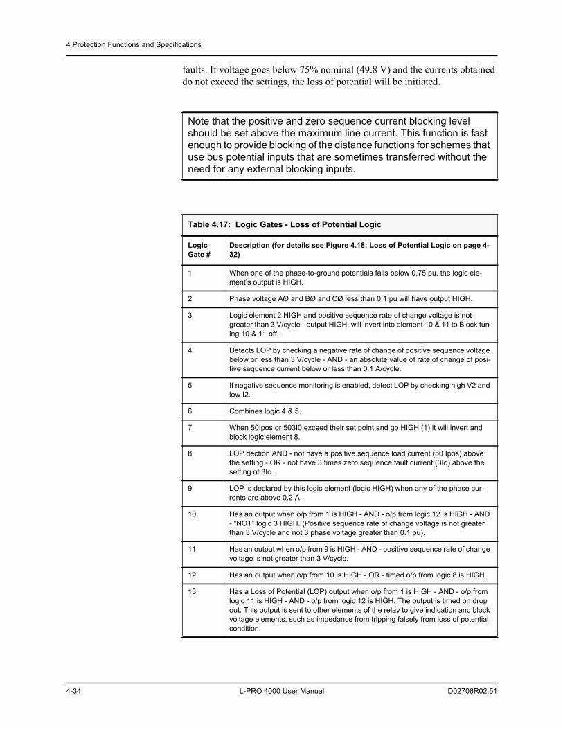
4 Protection Functions and Specifications
4-34 L-PRO 4000 User Manual D02706R02.51
faults. If voltage goes below 75% nominal (49.8 V) and the currents obtained do not exceed the settings, the loss of potential will be initiated.
Note that the positive and zero sequence current blocking level should be set above the maximum line current. This function is fast enough to provide blocking of the distance functions for schemes that use bus potential inputs that are sometimes transferred without the need for any external blocking inputs.
Table 4.17: Logic Gates - Loss of Potential Logic
Logic Gate #
Description (for details see Figure 4.18: Loss of Potential Logic on page 4-32)
1 When one of the phase-to-ground potentials falls below 0.75 pu, the logic ele-ment’s output is HIGH.
2 Phase voltage AØ and BØ and CØ less than 0.1 pu will have output HIGH.
3 Logic element 2 HIGH and positive sequence rate of change voltage is not greater than 3 V/cycle - output HIGH, will invert into element 10 & 11 to Block tun-ing 10 & 11 off.
4 Detects LOP by checking a negative rate of change of positive sequence voltage below or less than 3 V/cycle - AND - an absolute value of rate of change of posi-tive sequence current below or less than 0.1 A/cycle.
5 If negative sequence monitoring is enabled, detect LOP by checking high V2 and low I2.
6 Combines logic 4 & 5.
7 When 50Ipos or 503I0 exceed their set point and go HIGH (1) it will invert and block logic element 8.
8 LOP dection AND - not have a positive sequence load current (50 Ipos) above the setting.- OR - not have 3 times zero sequence fault current (3Io) above the setting of 3Io.
9 LOP is declared by this logic element (logic HIGH) when any of the phase cur-rents are above 0.2 A.
10 Has an output when o/p from 1 is HIGH - AND - o/p from logic 12 is HIGH - AND - “NOT” logic 3 HIGH. (Positive sequence rate of change voltage is not greater than 3 V/cycle and not 3 phase voltage greater than 0.1 pu).
11 Has an output when o/p from 9 is HIGH - AND - positive sequence rate of change voltage is not greater than 3 V/cycle.
12 Has an output when o/p from 10 is HIGH - OR - timed o/p from logic 8 is HIGH.
13 Has a Loss of Potential (LOP) output when o/p from 1 is HIGH - AND - o/p from logic 11 is HIGH - AND - o/p from logic 12 is HIGH. The output is timed on drop out. This output is sent to other elements of the relay to give indication and block voltage elements, such as impedance from tripping falsely from loss of potential condition.
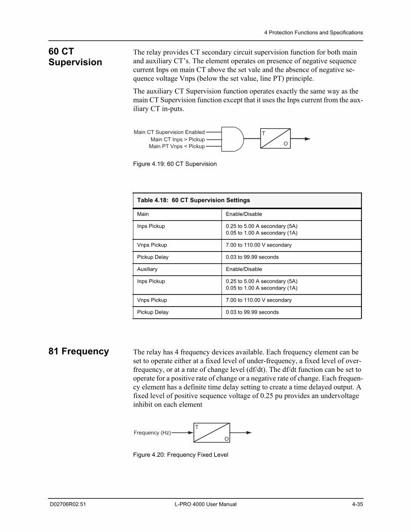
4 Protection Functions and Specifications
D02706R02.51 L-PRO 4000 User Manual 4-35
60 CT Supervision
The relay provides CT secondary circuit supervision function for both main and auxiliary CT’s. The element operates on presence of negative sequence current Inps on main CT above the set vale and the absence of negative se-quence voltage Vnps (below the set value, line PT) principle.
The auxiliary CT Supervision function operates exactly the same way as the main CT Supervision function except that it uses the Inps current from the aux-iliary CT in-puts.
Figure 4.19: 60 CT Supervision
81 Frequency The relay has 4 frequency devices available. Each frequency element can be set to operate either at a fixed level of under-frequency, a fixed level of over-frequency, or at a rate of change level (df/dt). The df/dt function can be set to operate for a positive rate of change or a negative rate of change. Each frequen-cy element has a definite time delay setting to create a time delayed output. A fixed level of positive sequence voltage of 0.25 pu provides an undervoltage inhibit on each element
Figure 4.20: Frequency Fixed Level
Table 4.18: 60 CT Supervision Settings
Main Enable/Disable
Inps Pickup 0.25 to 5.00 A secondary (5A)0.05 to 1.00 A secondary (1A)
Vnps Pickup 7.00 to 110.00 V secondary
Pickup Delay 0.03 to 99.99 seconds
Auxiliary Enable/Disable
Inps Pickup 0.25 to 5.00 A secondary (5A)0.05 to 1.00 A secondary (1A)
Vnps Pickup 7.00 to 110.00 V secondary
Pickup Delay 0.03 to 99.99 seconds
Main CT Supervision EnabledMain CT Inps > Pickup
Main PT Vnps < Pickup
T
O
T
O
Frequency (Hz)
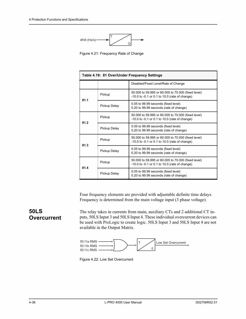
4 Protection Functions and Specifications
4-36 L-PRO 4000 User Manual D02706R02.51
Figure 4.21: Frequency Rate of Change
Four frequency elements are provided with adjustable definite time delays. Frequency is determined from the main voltage input (3 phase voltage).
50LS Overcurrent
The relay takes in currents from main, auxiliary CTs and 2 additional CT in-puts, 50LS Input 3 and 50LS Input 4. These individual overcurrent devices can be used with ProLogic to create logic. 50LS Input 3 and 50LS Input 4 are not available in the Output Matrix.
Figure 4.22: Low Set Overcurrent
Table 4.19: 81 Over/Under Frequency Settings
Disabled/Fixed Level/Rate of Change
81.1
Pickup 50.000 to 59.995 or 60.005 to 70.000 (fixed level)-10.0 to -0.1 or 0.1 to 10.0 (rate of change)
Pickup Delay 0.05 to 99.99 seconds (fixed level)0.20 to 99.99 seconds (rate of change)
81.2
Pickup 50.000 to 59.995 or 60.005 to 70.000 (fixed level)-10.0 to -0.1 or 0.1 to 10.0 (rate of change)
Pickup Delay 0.05 to 99.99 seconds (fixed level)0.20 to 99.99 seconds (rate of change)
81.3
Pickup 50.000 to 59.995 or 60.005 to 70.000 (fixed level)-10.0 to -0.1 or 0.1 to 10.0 (rate of change)
Pickup Delay 0.05 to 99.99 seconds (fixed level)0.20 to 99.99 seconds (rate of change)
81.4
Pickup 50.000 to 59.995 or 60.005 to 70.000 (fixed level)-10.0 to -0.1 or 0.1 to 10.0 (rate of change)
Pickup Delay 0.05 to 99.99 seconds (fixed level)0.20 to 99.99 seconds (rate of change)
T
O
df/dt (Hz/s)
50 I1a RMS
50 I1b RMS
50 I1c RMS 0
T Low Set Overcurrent
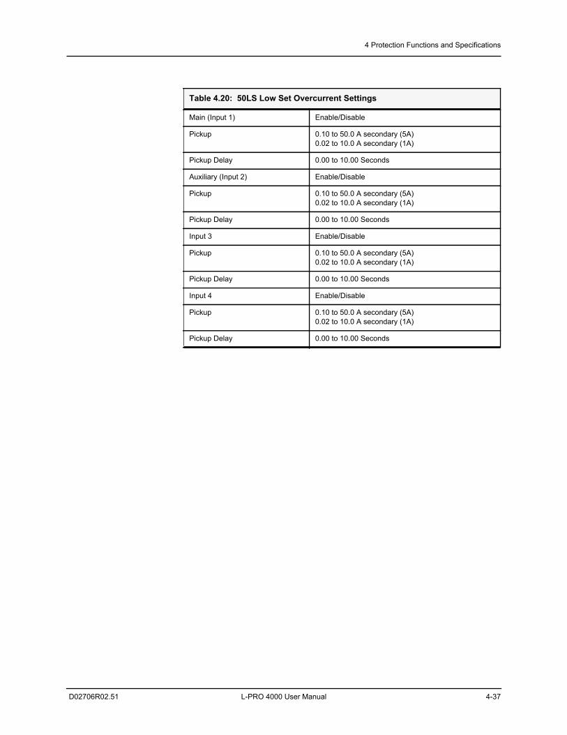
4 Protection Functions and Specifications
D02706R02.51 L-PRO 4000 User Manual 4-37
Table 4.20: 50LS Low Set Overcurrent Settings
Main (Input 1) Enable/Disable
Pickup 0.10 to 50.0 A secondary (5A)0.02 to 10.0 A secondary (1A)
Pickup Delay 0.00 to 10.00 Seconds
Auxiliary (Input 2) Enable/Disable
Pickup 0.10 to 50.0 A secondary (5A)0.02 to 10.0 A secondary (1A)
Pickup Delay 0.00 to 10.00 Seconds
Input 3 Enable/Disable
Pickup 0.10 to 50.0 A secondary (5A)0.02 to 10.0 A secondary (1A)
Pickup Delay 0.00 to 10.00 Seconds
Input 4 Enable/Disable
Pickup 0.10 to 50.0 A secondary (5A)0.02 to 10.0 A secondary (1A)
Pickup Delay 0.00 to 10.00 Seconds
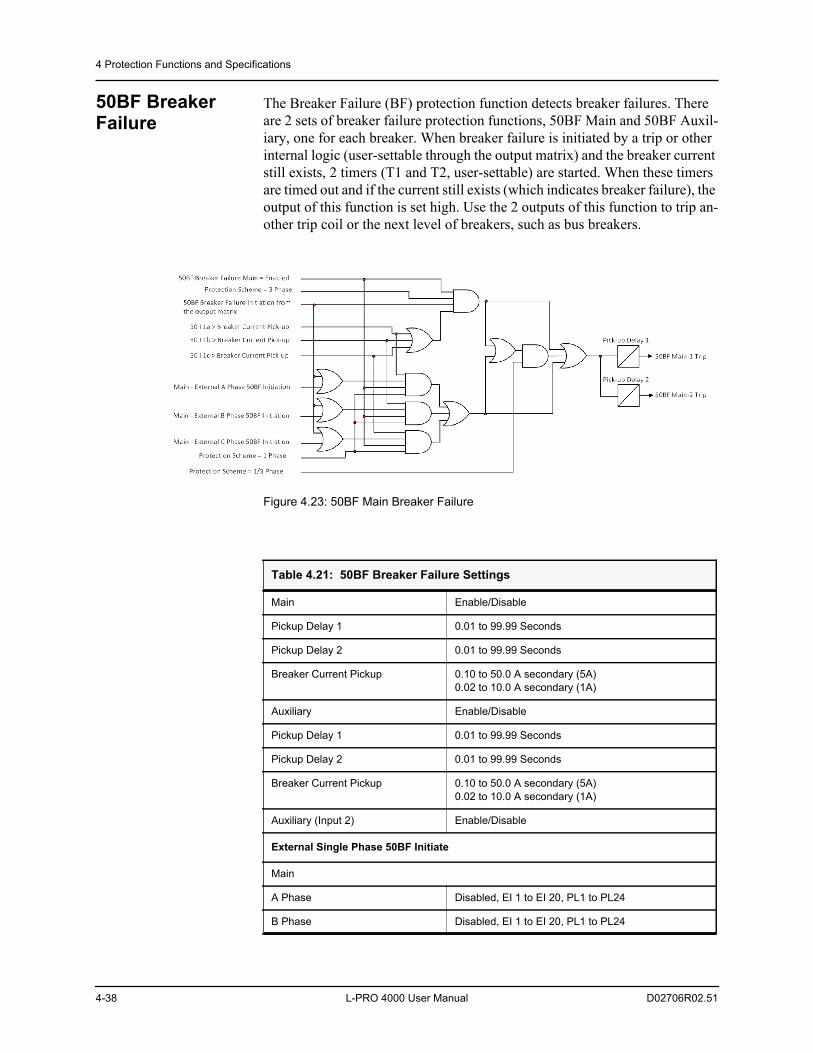
4 Protection Functions and Specifications
4-38 L-PRO 4000 User Manual D02706R02.51
50BF Breaker Failure
The Breaker Failure (BF) protection function detects breaker failures. There are 2 sets of breaker failure protection functions, 50BF Main and 50BF Auxil-iary, one for each breaker. When breaker failure is initiated by a trip or other internal logic (user-settable through the output matrix) and the breaker current still exists, 2 timers (T1 and T2, user-settable) are started. When these timers are timed out and if the current still exists (which indicates breaker failure), the output of this function is set high. Use the 2 outputs of this function to trip an-other trip coil or the next level of breakers, such as bus breakers.
Figure 4.23: 50BF Main Breaker Failure
Table 4.21: 50BF Breaker Failure Settings
Main Enable/Disable
Pickup Delay 1 0.01 to 99.99 Seconds
Pickup Delay 2 0.01 to 99.99 Seconds
Breaker Current Pickup 0.10 to 50.0 A secondary (5A)0.02 to 10.0 A secondary (1A)
Auxiliary Enable/Disable
Pickup Delay 1 0.01 to 99.99 Seconds
Pickup Delay 2 0.01 to 99.99 Seconds
Breaker Current Pickup 0.10 to 50.0 A secondary (5A)0.02 to 10.0 A secondary (1A)
Auxiliary (Input 2) Enable/Disable
External Single Phase 50BF Initiate
Main
A Phase Disabled, EI 1 to EI 20, PL1 to PL24
B Phase Disabled, EI 1 to EI 20, PL1 to PL24
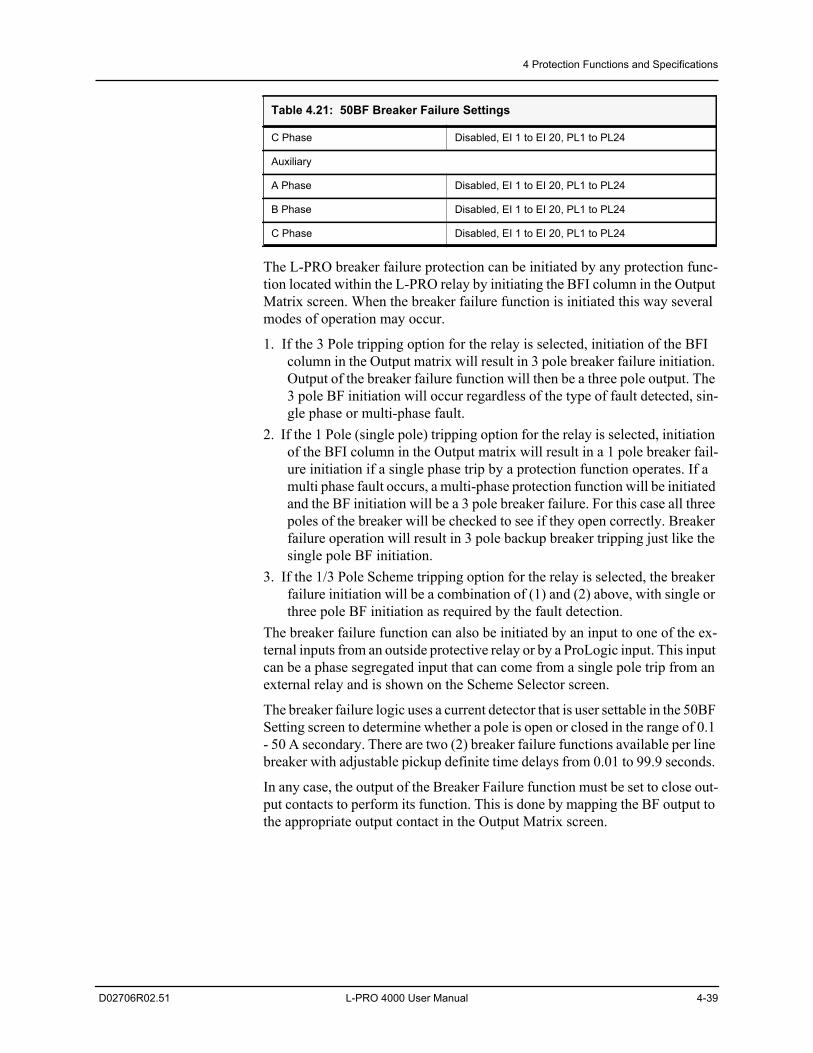
4 Protection Functions and Specifications
D02706R02.51 L-PRO 4000 User Manual 4-39
The L-PRO breaker failure protection can be initiated by any protection func-tion located within the L-PRO relay by initiating the BFI column in the Output Matrix screen. When the breaker failure function is initiated this way several modes of operation may occur.
1. If the 3 Pole tripping option for the relay is selected, initiation of the BFI column in the Output matrix will result in 3 pole breaker failure initiation. Output of the breaker failure function will then be a three pole output. The 3 pole BF initiation will occur regardless of the type of fault detected, sin-gle phase or multi-phase fault.
2. If the 1 Pole (single pole) tripping option for the relay is selected, initiation of the BFI column in the Output matrix will result in a 1 pole breaker fail-ure initiation if a single phase trip by a protection function operates. If a multi phase fault occurs, a multi-phase protection function will be initiated and the BF initiation will be a 3 pole breaker failure. For this case all three poles of the breaker will be checked to see if they open correctly. Breaker failure operation will result in 3 pole backup breaker tripping just like the single pole BF initiation.
3. If the 1/3 Pole Scheme tripping option for the relay is selected, the breaker failure initiation will be a combination of (1) and (2) above, with single or three pole BF initiation as required by the fault detection.
The breaker failure function can also be initiated by an input to one of the ex-ternal inputs from an outside protective relay or by a ProLogic input. This input can be a phase segregated input that can come from a single pole trip from an external relay and is shown on the Scheme Selector screen.
The breaker failure logic uses a current detector that is user settable in the 50BF Setting screen to determine whether a pole is open or closed in the range of 0.1 - 50 A secondary. There are two (2) breaker failure functions available per line breaker with adjustable pickup definite time delays from 0.01 to 99.9 seconds.
In any case, the output of the Breaker Failure function must be set to close out-put contacts to perform its function. This is done by mapping the BF output to the appropriate output contact in the Output Matrix screen.
C Phase Disabled, EI 1 to EI 20, PL1 to PL24
Auxiliary
A Phase Disabled, EI 1 to EI 20, PL1 to PL24
B Phase Disabled, EI 1 to EI 20, PL1 to PL24
C Phase Disabled, EI 1 to EI 20, PL1 to PL24
Table 4.21: 50BF Breaker Failure Settings
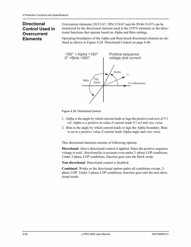
4 Protection Functions and Specifications
4-40 L-PRO 4000 User Manual D02706R02.51
Directional Control Used in Overcurrent Elements
Overcurrent elements (50/51/67, 50N/51N/67 and 46-50/46-51/67) can be monitored by the directional element used in the 21P/N elements or the direc-tional functions that operate based on Alpha and Beta settings.
Operating boundaries of the Alpha and Beta based directional element are de-fined as shown in Figure 4.24: Directional Control on page 4-40.
Figure 4.24: Directional Control
1. Alpha is the angle by which current leads or lags the positive real axis of V1 ref. Alpha is a positive in value if current leads V1 ref and vice versa.
2. Beta is the angle by which current leads or lags the Alpha boundary. Beta is set to a positive value if current leads Alpha angle and vice versa.
This directional function consists of following options.
Directional: Above directional control is applied. Since the positive sequence voltage is used , directionality is accurate even under 2- phase LOP conditions. Under 3-phase LOP conditions, function goes into the block mode.
Non-directional: Directional control is disabled.
Combined: Works as the directional option under all conditions except, 3-phase LOP. Under 3-phase LOP conditions, function goes into the non-direc-tional mode.
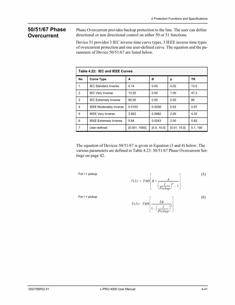
4 Protection Functions and Specifications
D02706R02.51 L-PRO 4000 User Manual 4-41
50/51/67 Phase Overcurrent
Phase Overcurrent provides backup protection to the line. The user can define directional or non directional control on either 50 or 51 functions.
Device 51 provides 3 IEC inverse time curve types, 3 IEEE inverse time types of overcurrent protection and one user-defined curve. The equation and the pa-rameters of Device 50/51/67 are listed below.
The equation of Devices 50/51/67 is given in Equation (3 and 4) below. The various parameters are defined in Table 4.23: 50/51/67 Phase Overcurrent Set-tings on page 42.
Table 4.22: IEC and IEEE Curves
No Curve Type A B p TR
1 IEC Standard Inverse 0.14 0.00 0.02 13.5
2 IEC Very Inverse 13.50 0.00 1.00 47.3
3 IEC Extremely Inverse 80.00 0.00 2.00 80
4 IEEE Moderately Inverse 0.0103 0.0228 0.02 0.97
5 IEEE Very Inverse 3.922 0.0982 2.00 4.32
6 IEEE Extremely Inverse 5.64 0.0243 2.00 5.82
7 User-defined [0.001, 1000] [0.0, 10.0] [0.01, 10.0] 0.1, 100
For I > pickup (5)
For I < pickup (6)
T I TMS B AI
Pickup------------------ p
1–------------------------------------+=
T I TMS TR
1 IPickup------------------ 2
–-----------------------------------=
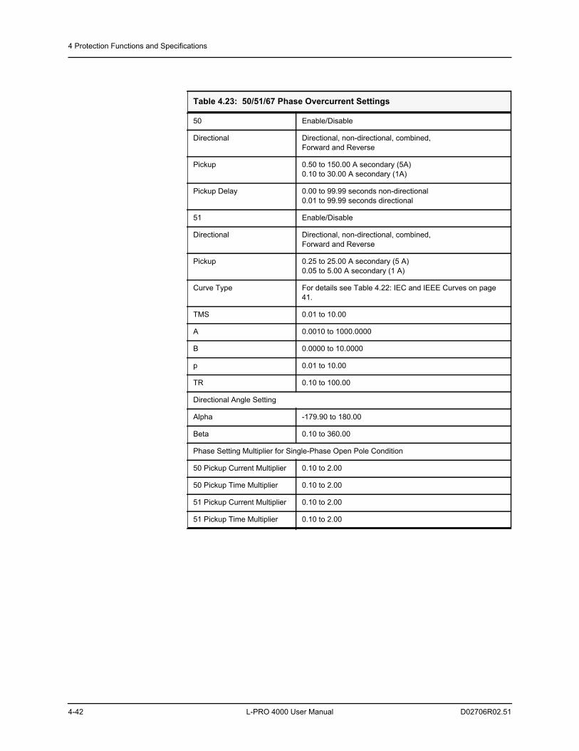
4 Protection Functions and Specifications
4-42 L-PRO 4000 User Manual D02706R02.51
Table 4.23: 50/51/67 Phase Overcurrent Settings
50 Enable/Disable
Directional Directional, non-directional, combined,Forward and Reverse
Pickup 0.50 to 150.00 A secondary (5A)0.10 to 30.00 A secondary (1A)
Pickup Delay 0.00 to 99.99 seconds non-directional0.01 to 99.99 seconds directional
51 Enable/Disable
Directional Directional, non-directional, combined,Forward and Reverse
Pickup 0.25 to 25.00 A secondary (5 A)0.05 to 5.00 A secondary (1 A)
Curve Type For details see Table 4.22: IEC and IEEE Curves on page 41.
TMS 0.01 to 10.00
A 0.0010 to 1000.0000
B 0.0000 to 10.0000
p 0.01 to 10.00
TR 0.10 to 100.00
Directional Angle Setting
Alpha -179.90 to 180.00
Beta 0.10 to 360.00
Phase Setting Multiplier for Single-Phase Open Pole Condition
50 Pickup Current Multiplier 0.10 to 2.00
50 Pickup Time Multiplier 0.10 to 2.00
51 Pickup Current Multiplier 0.10 to 2.00
51 Pickup Time Multiplier 0.10 to 2.00
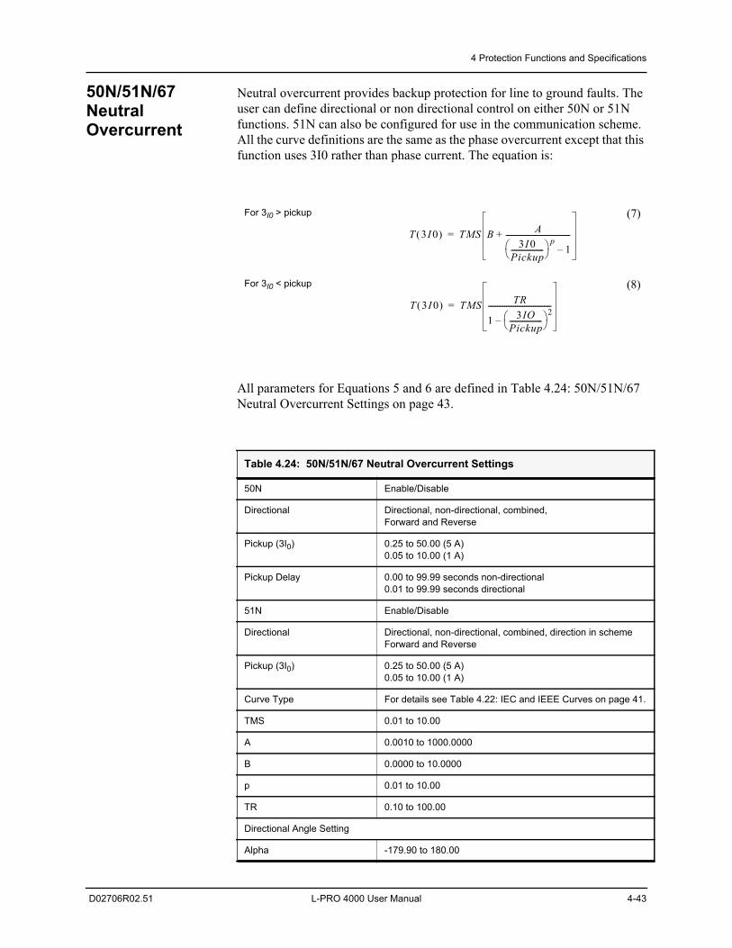
4 Protection Functions and Specifications
D02706R02.51 L-PRO 4000 User Manual 4-43
50N/51N/67 Neutral Overcurrent
Neutral overcurrent provides backup protection for line to ground faults. The user can define directional or non directional control on either 50N or 51N functions. 51N can also be configured for use in the communication scheme. All the curve definitions are the same as the phase overcurrent except that this function uses 3I0 rather than phase current. The equation is:
All parameters for Equations 5 and 6 are defined in Table 4.24: 50N/51N/67 Neutral Overcurrent Settings on page 43.
For 3I0 > pickup (7)
For 3I0 < pickup (8)
Table 4.24: 50N/51N/67 Neutral Overcurrent Settings
50N Enable/Disable
Directional Directional, non-directional, combined,Forward and Reverse
Pickup (3I0) 0.25 to 50.00 (5 A)0.05 to 10.00 (1 A)
Pickup Delay 0.00 to 99.99 seconds non-directional0.01 to 99.99 seconds directional
51N Enable/Disable
Directional Directional, non-directional, combined, direction in schemeForward and Reverse
Pickup (3I0) 0.25 to 50.00 (5 A)0.05 to 10.00 (1 A)
Curve Type For details see Table 4.22: IEC and IEEE Curves on page 41.
TMS 0.01 to 10.00
A 0.0010 to 1000.0000
B 0.0000 to 10.0000
p 0.01 to 10.00
TR 0.10 to 100.00
Directional Angle Setting
Alpha -179.90 to 180.00
T 3I 0 TMS B A3I 0
Pickup------------------ p
1–------------------------------------+=
T 3I 0 TMS TR
1 3IOPickup------------------ 2
–-----------------------------------=
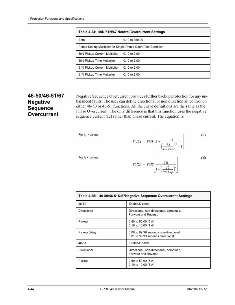
4 Protection Functions and Specifications
4-44 L-PRO 4000 User Manual D02706R02.51
46-50/46-51/67 Negative Sequence Overcurrent
Negative Sequence Overcurrent provides further backup protection for any un-balanced faults. The user can define directional or non direction all control on either 46-50 or 46-51 functions. All the curve definitions are the same as the Phase Overcurrent. The only difference is that this function uses the negative sequence current (I2) rather than phase current. The equation is:
Beta 0.10 to 360.00
Phase Setting Multiplier for Single Phase Open Pole Condition
50N Pickup Current Multiplier 0.10 to 2.00
50N Pickup Time Multiplier 0.10 to 2.00
51N Pickup Current Multiplier 0.10 to 2.00
51N Pickup Time Multiplier 0.10 to 2.00
Table 4.24: 50N/51N/67 Neutral Overcurrent Settings
For I2 > pickup (9)
For I2 < pickup (10)
Table 4.25: 46-50/46-51N/67Negative Sequence Overcurrent Settings
46-50 Enable/Disable
Directional Directional, non-directional, combined,Forward and Reverse
Pickup 0.50 to 50.00 (5 A)0.10 to 10.00 (1 A)
Pickup Delay 0.00 to 99.99 seconds non-directional0.01 to 99.99 seconds directional
46-51 Enable/Disable
Directional Directional, non-directional, combined,Forward and Reverse
Pickup 0.50 to 50.00 (5 A)0.10 to 10.00 (1 A)
T I 2 TMS B AI 2
Pickup------------------ p
1–------------------------------------+=
T I 2 TMS TR
1 I 2Pickup------------------ 2
–-----------------------------------=
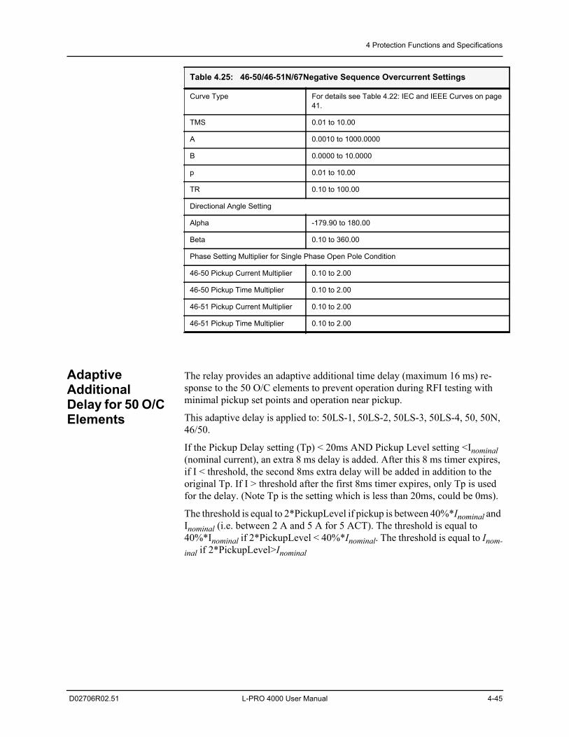
4 Protection Functions and Specifications
D02706R02.51 L-PRO 4000 User Manual 4-45
Adaptive Additional Delay for 50 O/C Elements
The relay provides an adaptive additional time delay (maximum 16 ms) re-sponse to the 50 O/C elements to prevent operation during RFI testing with minimal pickup set points and operation near pickup.
This adaptive delay is applied to: 50LS-1, 50LS-2, 50LS-3, 50LS-4, 50, 50N, 46/50.
If the Pickup Delay setting (Tp) < 20ms AND Pickup Level setting <Inominal (nominal current), an extra 8 ms delay is added. After this 8 ms timer expires, if I < threshold, the second 8ms extra delay will be added in addition to the original Tp. If I > threshold after the first 8ms timer expires, only Tp is used for the delay. (Note Tp is the setting which is less than 20ms, could be 0ms).
The threshold is equal to 2*PickupLevel if pickup is between 40%*Inominal and Inominal (i.e. between 2 A and 5 A for 5 ACT). The threshold is equal to 40%*Inominal if 2*PickupLevel < 40%*Inominal. The threshold is equal to Inom-inal if 2*PickupLevel>Inominal
Curve Type For details see Table 4.22: IEC and IEEE Curves on page 41.
TMS 0.01 to 10.00
A 0.0010 to 1000.0000
B 0.0000 to 10.0000
p 0.01 to 10.00
TR 0.10 to 100.00
Directional Angle Setting
Alpha -179.90 to 180.00
Beta 0.10 to 360.00
Phase Setting Multiplier for Single Phase Open Pole Condition
46-50 Pickup Current Multiplier 0.10 to 2.00
46-50 Pickup Time Multiplier 0.10 to 2.00
46-51 Pickup Current Multiplier 0.10 to 2.00
46-51 Pickup Time Multiplier 0.10 to 2.00
Table 4.25: 46-50/46-51N/67Negative Sequence Overcurrent Settings
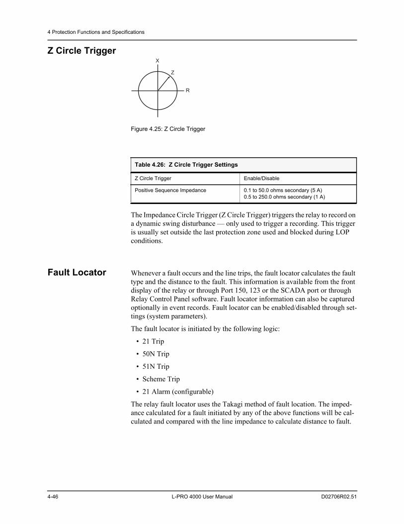
4 Protection Functions and Specifications
4-46 L-PRO 4000 User Manual D02706R02.51
Z Circle Trigger
Figure 4.25: Z Circle Trigger
The Impedance Circle Trigger (Z Circle Trigger) triggers the relay to record on a dynamic swing disturbance — only used to trigger a recording. This trigger is usually set outside the last protection zone used and blocked during LOP conditions.
Fault Locator Whenever a fault occurs and the line trips, the fault locator calculates the fault type and the distance to the fault. This information is available from the front display of the relay or through Port 150, 123 or the SCADA port or through Relay Control Panel software. Fault locator information can also be captured optionally in event records. Fault locator can be enabled/disabled through set-tings (system parameters).
The fault locator is initiated by the following logic:
• 21 Trip
• 50N Trip
• 51N Trip
• Scheme Trip
• 21 Alarm (configurable)
The relay fault locator uses the Takagi method of fault location. The imped-ance calculated for a fault initiated by any of the above functions will be cal-culated and compared with the line impedance to calculate distance to fault.
Table 4.26: Z Circle Trigger Settings
Z Circle Trigger Enable/Disable
Positive Sequence Impedance 0.1 to 50.0 ohms secondary (5 A)0.5 to 250.0 ohms secondary (1 A)
X
Z
R
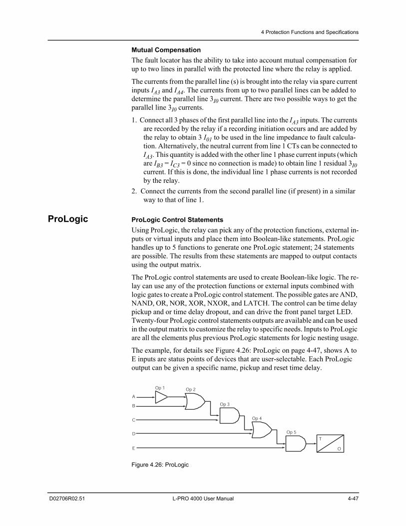
4 Protection Functions and Specifications
D02706R02.51 L-PRO 4000 User Manual 4-47
Mutual CompensationThe fault locator has the ability to take into account mutual compensation for up to two lines in parallel with the protected line where the relay is applied.
The currents from the parallel line (s) is brought into the relay via spare current inputs IA3 and IA4. The currents from up to two parallel lines can be added to determine the parallel line 3I0 current. There are two possible ways to get the parallel line 3I0 currents.
1. Connect all 3 phases of the first parallel line into the IA3 inputs. The currents are recorded by the relay if a recording initiation occurs and are added by the relay to obtain 3 I01 to be used in the line impedance to fault calcula-tion. Alternatively, the neutral current from line 1 CTs can be connected to IA3. This quantity is added with the other line 1 phase current inputs (which are IB3 = IC3 = 0 since no connection is made) to obtain line 1 residual 3I0 current. If this is done, the individual line 1 phase currents is not recorded by the relay.
2. Connect the currents from the second parallel line (if present) in a similar way to that of line 1.
ProLogic ProLogic Control StatementsUsing ProLogic, the relay can pick any of the protection functions, external in-puts or virtual inputs and place them into Boolean-like statements. ProLogic handles up to 5 functions to generate one ProLogic statement; 24 statements are possible. The results from these statements are mapped to output contacts using the output matrix.
The ProLogic control statements are used to create Boolean-like logic. The re-lay can use any of the protection functions or external inputs combined with logic gates to create a ProLogic control statement. The possible gates are AND, NAND, OR, NOR, XOR, NXOR, and LATCH. The control can be time delay pickup and or time delay dropout, and can drive the front panel target LED. Twenty-four ProLogic control statements outputs are available and can be used in the output matrix to customize the relay to specific needs. Inputs to ProLogic are all the elements plus previous ProLogic statements for logic nesting usage.
The example, for details see Figure 4.26: ProLogic on page 4-47, shows A to E inputs are status points of devices that are user-selectable. Each ProLogic output can be given a specific name, pickup and reset time delay.
Figure 4.26: ProLogic
T
O
A
B
C
D
E
Op 1 Op 2
Op 3
Op 4
Op 5
4 Protection Functions and Specifications
4-48 L-PRO 4000 User Manual D02706R02.51
Group Logic Group Logic Control StatementsThe relay has 8 Setting Groups (SG). The user can change all relay setting pa-rameters except the physical connections such as input or output parameters in each setting group. Setting group changes are performed by using any one of the 16 available Group Logic statements per setting group. The Group Logic statements are similar to the ProLogic statements with the following excep-tions – the sole function is to activate one of the 8 setting groups and the pro-cessing is in a slower half second cycle. Group Logic inputs statements are driven from ProLogic or any external input or virtual input or from previous Group Logic statements. Each Group Logic statement includes 5 inputs (with Boolean statements), one latch state and one pickup delay timer. The Active Setting Group (ASG) is viewed from the Terminal Mode, the front panel or from a record stored by the relay, the ASG is stored with the record).
Group Logic ProcessingThe 16 Group Logic statements reside in a slower processing thread within the relay protection algorithms. The processing cycle happens once every half sec-ond (0.5 second). When using ProLogic statements remember that a latch or dropout timer should be used if the initiating condition does not last at least 0.5 seconds. In the example following, we will create a definite pulse length using ProLogic, for details see “L-PRO Setting Example” in Appendix L.
Default Setting GroupThe relay uses Setting Group 1 as the factory default setting group and retains the current active setting group in memory. This allows the relay to use the last active setting group prior to interruption of relay power as the default setting group following power up.
Change Active GroupThe user can at any time change the active setting group. When initiating a set-ting group change, this change takes precedence over an automatic setting group change.
Table 4.27: ProLogic Setting Functions
Name Give the ProLogic a meaningful name
Pickup Delay Delay time from pickup to operate
Dropout Delay Delay time from dropout to a ProLogic status of low
A, B, C, D, E Relay elements as input statements
Operators Boolean-type logic gates
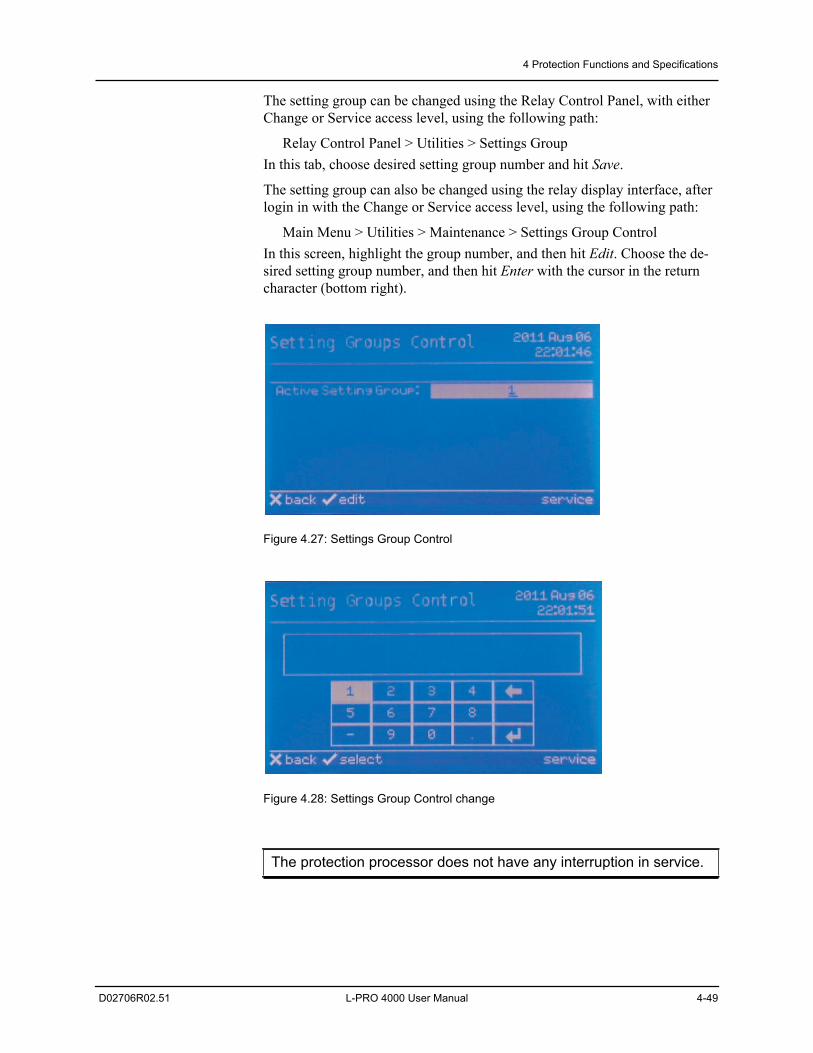
4 Protection Functions and Specifications
D02706R02.51 L-PRO 4000 User Manual 4-49
The setting group can be changed using the Relay Control Panel, with either Change or Service access level, using the following path:
Relay Control Panel > Utilities > Settings GroupIn this tab, choose desired setting group number and hit Save.
The setting group can also be changed using the relay display interface, after login in with the Change or Service access level, using the following path:
Main Menu > Utilities > Maintenance > Settings Group ControlIn this screen, highlight the group number, and then hit Edit. Choose the de-sired setting group number, and then hit Enter with the cursor in the return character (bottom right).
Figure 4.27: Settings Group Control
Figure 4.28: Settings Group Control change
The protection processor does not have any interruption in service.
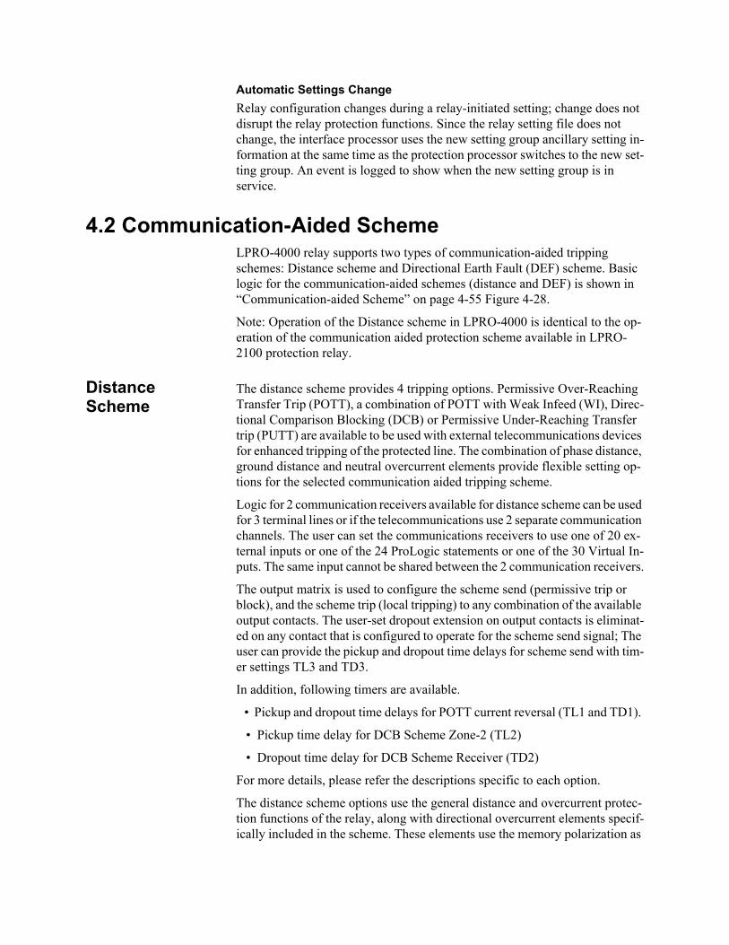
Automatic Settings ChangeRelay configuration changes during a relay-initiated setting; change does not disrupt the relay protection functions. Since the relay setting file does not change, the interface processor uses the new setting group ancillary setting in-formation at the same time as the protection processor switches to the new set-ting group. An event is logged to show when the new setting group is in service.
4.2 Communication-Aided SchemeLPRO-4000 relay supports two types of communication-aided tripping schemes: Distance scheme and Directional Earth Fault (DEF) scheme. Basic logic for the communication-aided schemes (distance and DEF) is shown in “Communication-aided Scheme” on page 4-55 Figure 4-28.
Note: Operation of the Distance scheme in LPRO-4000 is identical to the op-eration of the communication aided protection scheme available in LPRO-2100 protection relay.
Distance Scheme
The distance scheme provides 4 tripping options. Permissive Over-Reaching Transfer Trip (POTT), a combination of POTT with Weak Infeed (WI), Direc-tional Comparison Blocking (DCB) or Permissive Under-Reaching Transfer trip (PUTT) are available to be used with external telecommunications devices for enhanced tripping of the protected line. The combination of phase distance, ground distance and neutral overcurrent elements provide flexible setting op-tions for the selected communication aided tripping scheme.
Logic for 2 communication receivers available for distance scheme can be used for 3 terminal lines or if the telecommunications use 2 separate communication channels. The user can set the communications receivers to use one of 20 ex-ternal inputs or one of the 24 ProLogic statements or one of the 30 Virtual In-puts. The same input cannot be shared between the 2 communication receivers.
The output matrix is used to configure the scheme send (permissive trip or block), and the scheme trip (local tripping) to any combination of the available output contacts. The user-set dropout extension on output contacts is eliminat-ed on any contact that is configured to operate for the scheme send signal; The user can provide the pickup and dropout time delays for scheme send with tim-er settings TL3 and TD3.
In addition, following timers are available.
• Pickup and dropout time delays for POTT current reversal (TL1 and TD1).
• Pickup time delay for DCB Scheme Zone-2 (TL2)
• Dropout time delay for DCB Scheme Receiver (TD2)
For more details, please refer the descriptions specific to each option.
The distance scheme options use the general distance and overcurrent protec-tion functions of the relay, along with directional overcurrent elements specif-ically included in the scheme. These elements use the memory polarization as
4 Protection Functions and Specifications
D02706R02.51 L-PRO 4000 User Manual 4-51
described in the “Relay Method of Memory Polarization” on page 4-7 and the directional element as described in “Directional Element” on page 4-10.
50/51N - OC Carrier Trip and Block Logic
The carrier trip logic is traditionally initiated by the Zone 2 distance elements, but the relay provides 2 directional neutral overcurrent elements that can be used in addition to the Zone 2 distance elements. The device 51N time over-current element, and the 50N/67F instantaneous overcurrent if enabled can be configured to drive the carrier trip logic. The 51N is configured in the 50N/51N screen, while the 50N/67F is configured in the scheme selector screen, both el-ements are forward directional elements.
The scheme selector can also be configured to enable the 50N/67F and 50N/ 67R directional overcurrent elements as inputs to ProLogic statements. The 50N/67F element can be set to either forward directional or non-directional when selecting the action, “ProLogic Only”.
If the pickup delay setting (Tp) < 9 ms, then 9 ms will be used for the delay. Otherwise Tp will be used for the delay. This change is always applied regard-less of the direction setting (Non-dir, FWD, REV) and the 3I0 pickup level.
Note: If the directional element cannot determine a valid direction, the direc-tion is set to “forward”, the 50N/67F may operate, and the 50N/67R element is blocked. See “Directional Element” on page 4-10.
POTT Logic The POTT logic is used for tripping schemes where the local end over-reaches the remote end for forward fault conditions, for details see Figure 4.29: Com-munication-aided Scheme on page 4-55. The local end sends a permissive trip signal to the remote end when one of the forward directional elements operates.
The scheme send signal (permissive transfer trip send) is time delayed by timer setting TL3; the local end is required to sense a forward fault for durations greater than TL3. The local end does not produce a scheme trip output unless the remote has detected a forward directional fault and sends the similar per-missive trip signal to the local end. The local end senses a permissive trip re-ceive signal and the scheme trip closes the output contacts and removes the fault contribution from the local end. The remote end acts in a similar fashion and the fault contribution is removed from the remote end.
Current reversal logic guards against incorrect permissive tripping for installa-tions with parallel lines where one end of the un-faulted line is contributing fault current and the other end of the un-faulted line is over-reaching and send-ing a permissive trip signal. The local reverse directional elements are used with the permissive receive signal from the remote end to form the blocking logic. The blocking logic is time delayed by timer setting TL1; the local end is required to sense reverse faults while receiving the remote permissive trip for durations greater than TL1. The blocking logic continues to block the scheme send and scheme trip signals when the reverse fault detection or permissive trip receive signals go low. Timer setting TD1 determines the current reversal block extension time.
For line terminals with a weak source, fault conditions could occur on the pro-tected line where no elements operate at the weak source. Weak infeed (WI)
4 Protection Functions and Specifications
4-52 L-PRO 4000 User Manual D02706R02.51
logic enables the relay to protect lines where one end of the line has no source or has a very weak source. The WI scheme can only be enabled if the user has selected the POTT scheme otherwise it is disabled. If enabled, the WI feature enhances the POTT tripping logic.
WI enables the POTT scheme to quickly isolate line faults where one end of the line has a high source of impedance.
During fault conditions where no weak source elements pick up the WI logic echoes back the permissive transfer trip signal received by the weak source. If a permissive transfer trip is received from the remote line end, AND 110, AND 111 and OR 115 echo a POTT signal back to the remote end. The permissive transfer trip signal is required to last for durations greater than 20 ms. A 3 ms time delay pickup and time delay dropout timer TWD2 determine the amount of time between permissive transfer trip receive signals that the scheme echoes back. If the permissive transfer trip receive signal is constantly high the WI logic only echoes back for a time equal to TWD3 plus 3ms. If the PT signal being received resets then starts up again, after timer setting TWD2, a new per-missive transfer trip signal echoes back.
The WI logic blocks when forward or reverse faults are detected, the logic is also blocked for a loss of potential condition. During a reverse or a forward fault condition, the Zone 2, Zone 4, 51N, or 50N/67 elements could pick up. If any of these functions pick up, they block the WI scheme by putting a high in-put into inverted input of AND 110. The blocking condition is required last for durations greater than 6 ms. The blocking logic continues to block the scheme send and scheme trip signals when the fault detection or loss of potential sig-nals go low. Timer setting TWD1 determines the block extension time. TWD1 should be set to coordinate with the communication-reset time of the PT signal. It should be set greater than the time it takes for the remote end’s Zone 2 to re-set and for the PT channel to reset.
Timer setting TWD2 should be set to a time that prevents chattering of the communications channel. If TWD2 is allowed to reset before the remote end (strong source) clears the fault and stops sending the permissive transfer trip signal the WI echoes back another block of permissive transfer trip send.
The WI logic is also used to provide local tripping if both ends of the line are to be isolated. The line voltages provide supervision with a positive sequence under-voltage element (27V1) and a zero sequence over-voltage element (59V0). If a permissive transfer trip is received from the remote line end, AND 110, AND 112, OR 113 and OR 119 provide a local tripping signal.
DCB Logic The DCB logic is used for tripping schemes where the local end over-reaches the remote end for forward fault conditions, for details see Figure 4.29: Com-munication-aided Scheme on page 55. Typically DCB is used when the com-munications link may be disrupted during fault conditions, for example power line carrier.
The local end sends a block trip signal to the remote end when one of the en-abled reverse directional elements operates. The scheme send signal (block trip send) is time delayed by timer setting TL3, the local end is required to sense a
4 Protection Functions and Specifications
D02706R02.51 L-PRO 4000 User Manual 4-53
reverse fault for durations greater than TL3. If one of the forward directional elements operates the blocking logic does not operate. For forward directional fault conditions the DCB logic is time delayed by timer setting TL2. The for-ward fault condition has to last for durations greater than TL2. The local end does not produce a scheme trip output if the remote has detected a reverse di-rectional fault and sends the similar block trip signal to the local end. The local end senses a block trip receive signal and the scheme trip logic is disabled with no intentional delay. Current reversal logic guards against incorrect local trip-ping for installations with parallel lines where one end of the un-faulted line is contributing fault current and the other end of the un-faulted line is reverse reaching and sending a block trip signal. The local forward directional ele-ments are supervised by the block receive signal from the remote end to form the blocking logic. The blocking logic reset is time delayed by timer setting TD2; the local end is required to receive the remote block trip for durations greater than 0 ms. The blocking logic continues to block the scheme trip signals when the block trip receive signal goes low. Typically the block reset timer TD2 is set longer than the forward directional elements reset time.
PUTT Logic The PUTT logic is used for tripping schemes where the local end under-reach the remote end for close in forward fault conditions, for details see Figure 4.29: Communication-aided Scheme on page 55. The local end sends a permissive trip signal to the remote end when one of the forward directional elements op-erates (Zone 1 distance elements). The scheme send signal (permissive transfer trip send) is time delayed by timer setting TL3, the local end is required to sense a forward fault for durations greater than TL3. The remote end does not produce a scheme trip output unless a forward directional fault is detected and the local end has sent the permissive trip signal. The remote end senses a per-missive trip receive signal and the scheme trip closes the output contacts and removes the fault contribution from the remote end. The remote end can act quicker for fault conditions where the Zone 2 faults would be time delayed un-less the close in fault condition was not transferred by the scheme send.
DEF Scheme Although the 51N time overcurrent element and the 50N/67F instantaneous overcurrent element can be enabled as an option in the distance scheme (see above), it may not be desired for some applications due to the high sensitivity in overcurrent elements. For such applications, the DEF scheme can be used as an option. The DEF scheme provides Zone-2 monitoring to provide an extra security to the logic.
The DEF scheme provides the options “Permissive tripping” and “Blocking”. One communication receiver is available for the DEF scheme. The user can set the communications receiver to use one of 20 external inputs or one of the 24 ProLogic statements or one of the 24 Virtual Inputs.
Similar to the distance scheme, the output matrix is used to configure the scheme send (permissive trip or block), and the scheme trip (local tripping) to any combination of the available output contacts. The user-set dropout exten-sion on output contacts is eliminated on any contact that is configured to oper-ate for the scheme send signal; The user can provide the pickup and dropout time delay for scheme send with timer settings TL6 and TD6.
4 Protection Functions and Specifications
4-54 L-PRO 4000 User Manual D02706R02.51
Permissive Logic
Permissive scheme logic allows rapid fault clearing for sensitive earth fault conditions occurred within the protected line.
The local end sends a permissive trip signal to the remote end when the direc-tional element of overcurrent device recognizes a forward fault, for details see Figure 4.29: Communication-aided Scheme on page 55. The scheme send sig-nal (permissive transfer trip send) is time delayed by timer setting TL6, the lo-cal end is required to sense a forward fault for durations greater than TL6. The remote end does not produce a scheme trip output unless a forward directional ground fault is detected with 21N Zone2 pickup and the local end has sent the permissive trip signal.
Blocking Logic The basic operation of the block logic is very similar to the DCB logic in the distance scheme except the directionality is purely based on the overcurrent el-ement. Typically blocking logic is used when the communications link may be disrupted during fault conditions, for example power line carrier.
The local end sends a block trip signal to the remote end when the reverse di-rectional element operates. The scheme send signal (block trip send) is time de-layed by timer setting TL6, the local end is required to sense a reverse fault for durations greater than TL6. If one of the forward directional elements operates the blocking logic does not operate. For forward directional fault conditions the block logic is time delayed by 50 ms. The forward fault condition has to last for durations greater than 50ms. The local end does not produce a scheme trip output if the remote has detected a reverse directional fault and sends the similar block trip signal to the local end.
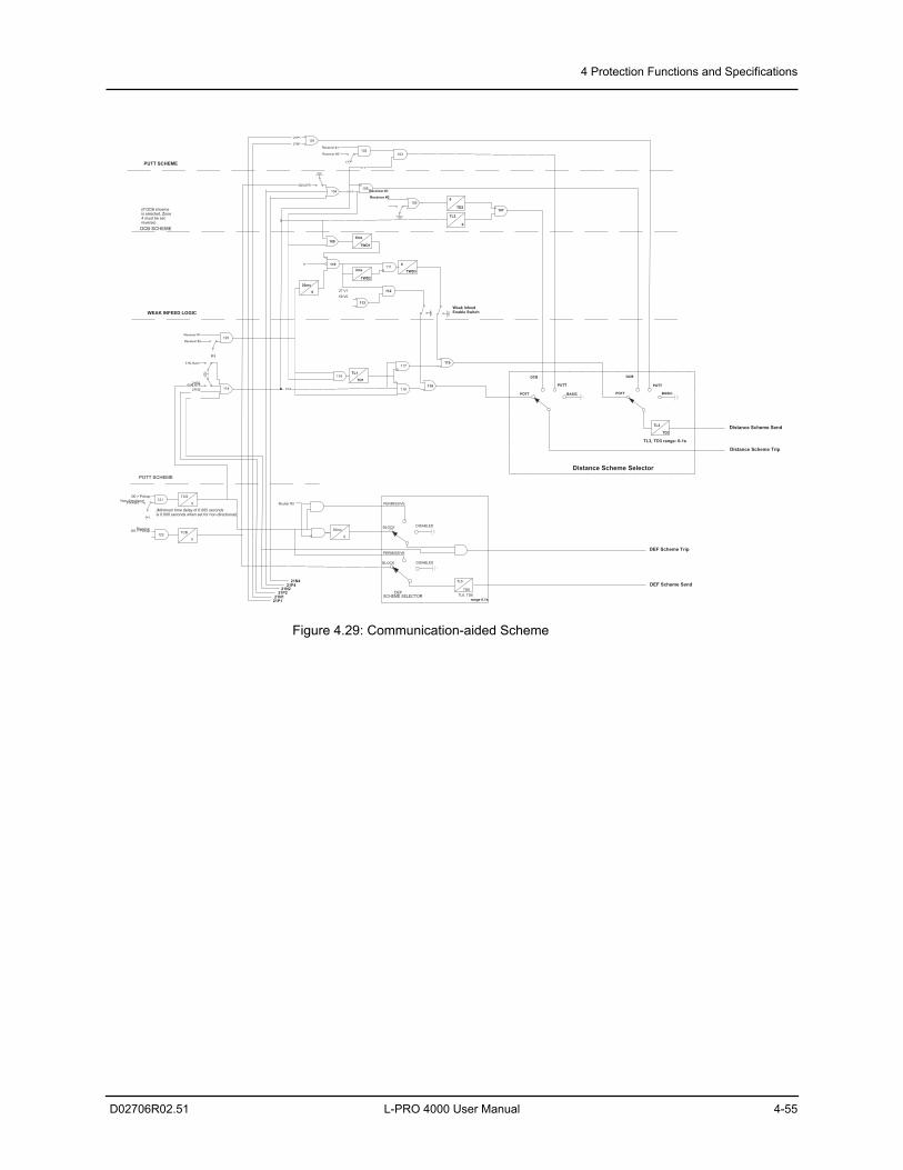
4 Protection Functions and Specifications
D02706R02.51 L-PRO 4000 User Manual 4-55
Figure 4.29: Communication-aided Scheme
PUTT SCHEME
DCB SCHEME
WEAK INFEED LOGIC
113
111
(If DCB shceme is selected, Zone 4 must be set reverse)
0
TWD33ms
TWD2
POTT SCHEME
118
117
Distance Scheme Send
102
104105
106
108
110
114
6ms
TWD1
TL2
0
103
0
TD2107
Receiver #1
Receiver #2
11220ms
0
60
27 V1 59 V0
120Receiver #1
Receiver #2
(+)
51N Alarm
50N-67F 21P2
21N2
50N-67R
101
TL1
TD1116
21-4 R
21-2
21-2 119
115
Weak Infeed Enable Switch
Receiver #1
Receiver #2
(+)
POTT BASIC
Distance Scheme Selector
PUTT
TL3, TD3 range: 0-1s
DCB
TL3
TD3
POTT BASIC
PUTT
DCB
Distance Scheme Trip
1213I0 > Pickup
Forward
(+)
Non-directional TCS
0
1223I0 > Pickup Reverse
TCB
0
21N1
21P1
(Minimum time delay of 0.005 secondsis 0.000 seconds when set for non-directional)
50ms
0
TL6
TD6TL6, TD6
range 0.1s
Router #3 PERMISSIVE
BLOCK DISABLED
DISABLED
DEF Scheme Trip
DEF Scheme Send
PERMISSIVE
BLOCK
DEFSCHEME SELECTOR
21N421P4
21N221P2
21N121P1
4 Protection Functions and Specifications
4-56 L-PRO 4000 User Manual D02706R02.51
4.3 Recording FunctionsIntroduction The relay has high speed fault recording and logging functions to allow the
user to analyze faults and to review the operation of the overall protection scheme. Slow speed swing recording can be used to analyze system stability. If the relay has reached its recording capacity, new records overwrite the oldest records.
Fault Recording The relay provides DFR-quality fault recording, capturing input signal wave-forms and external input states at a rate of 96 samples per cycle. Each record also contains the timing of the internal logic produced by the relay (e.g. Device 51 trip). Obtain this information by uploading the records from the relay via the Relay Control Panel file transfer process and view them with RecordBase View software.
The quantities recorded are:
• 18 analog channels (6 voltages and 12 currents) @ 96 samples/cycle which captures up to the 25th harmonic
• External inputs @ 1 ms resolution
• Protection element output signals @ 8 samples/cycle
• ProLogic signals @ 8 samples/cycle
• Active setting group
The recorded protection element output signals includes Phase segregated Start and Trip signals of the Distance trip, Backup Overcurrent, Back up Earth Fault, Overvoltage, Undervoltage and CB Fail Protection.
Parameters that are user-selectable with respect to recording transients:
• Record length (0.2 to 10.0 seconds => 12 to 600 cycles @ 60 Hz Base) with automatic extension to capture successive triggers
• Recorder triggering by any internal logic or external input signal (e.g. 52 A)
• Pre trigger time configurable between 0.10 to 2.00 seconds
4 Protection Functions and Specifications
D02706R02.51 L-PRO 4000 User Manual 4-57
Swing Recording
The relay records dynamic system responses allowing the user to analyze sys-tem stability and to provide a larger context for fault analysis. Swing records contain positive sequence phasor measurements and system frequency calcu-lated at a rate of 1 phasor per cycle. Swing records can extend to 2 minutes in duration.
The quantities recorded are:
• Positive sequence impedance (magnitude)
• Positive sequence voltage (magnitude)
• Positive sequence current (magnitude)
• 3-Phase Reactive Power (Vars)
• 3-Phase Real Power (Watts)
Event Recording
The event recording provides permanent storage for the event log. The user can create an event record automatically or manually. When the event auto save is enabled, an event record is created approximately every 250 events.
The user can initiate an event manually through the Relay Control Panel.
Record Initiation
Recording can be initiated automatically by the relay when a fault or abnormal condition is detected. Set the relay to initiate a fault record on activation of any of its trip or alarm functions or on assertion of any external digital inputs.
The assignment of fault record initiation to the various relay functions is done through the relay’s Output Matrix settings.
A recording can also be initiated manually through the Relay Control Panel. The commands Trigger Fault, Trigger Swing and Trigger Event are available under the following path:
Relay Control Panel > RecordsAlso the relay display provides the option to initiate Fault Recording, under the following path:
Main Menu > Records > Fault Recording
A swing record can take a couple of minutes to produce due to the long post-trigger time.

Record Duration and Extension
The length of each record is determined by the Record Length setting. Tran-sient record lengths can be set between 0.2 and 10.0 seconds; swing record lengths can be set between 60 and 120 seconds. Pre-trigger times are configu-rable between 0.10 to 2.00 seconds for transient records and fixed at 30 sec-onds for swing records and are included as part of the normal record length.
The relay automatically extends a record as required to capture consecutive triggers that are close together. If a trigger occurs while a recording is in prog-ress, the record is extended to include the full post-trigger time of subsequent triggers, up to a maximum length —12.0 seconds for transient records; 180 seconds for swing records. If a trigger occurs before the end of a record caused by a previous trigger, but too late to allow sufficient post-trigger time in a max-imum extended record, a new overlapping record is created.
The normal record length settings are accessible under the Record Length heading of the relay settings, and can be set with the Offliner Settings software.
Record Storage The relay compresses records on the fly, achieving a typical lossless compres-sion rate of 4:1. As a result, the relay can store up to 75 x 2 second transient records, or up to 75 x 120 seconds swing records, or a combination of 75 tran-sient, swing and optionally event records. If the storage is full, new records au-tomatically overwrite the oldest, ensuring that the recording function is always available.
Record Retrieval and Deletion
A listing of stored records is available through the Relay Control Panel under the Records > List menu. The listing transfers records to a connected PC and deletes them from storage.
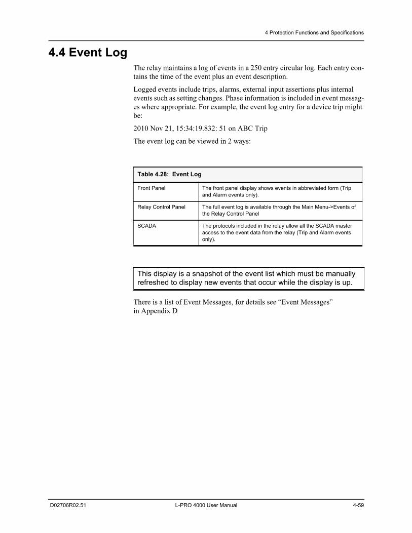
4 Protection Functions and Specifications
D02706R02.51 L-PRO 4000 User Manual 4-59
4.4 Event LogThe relay maintains a log of events in a 250 entry circular log. Each entry con-tains the time of the event plus an event description.
Logged events include trips, alarms, external input assertions plus internal events such as setting changes. Phase information is included in event messag-es where appropriate. For example, the event log entry for a device trip might be:
2010 Nov 21, 15:34:19.832: 51 on ABC Trip
The event log can be viewed in 2 ways:
There is a list of Event Messages, for details see “Event Messages” in Appendix D
Table 4.28: Event Log
Front Panel The front panel display shows events in abbreviated form (Trip and Alarm events only).
Relay Control Panel The full event log is available through the Main Menu->Events of the Relay Control Panel
SCADA The protocols included in the relay allow all the SCADA master access to the event data from the relay (Trip and Alarm events only).
This display is a snapshot of the event list which must be manually refreshed to display new events that occur while the display is up.
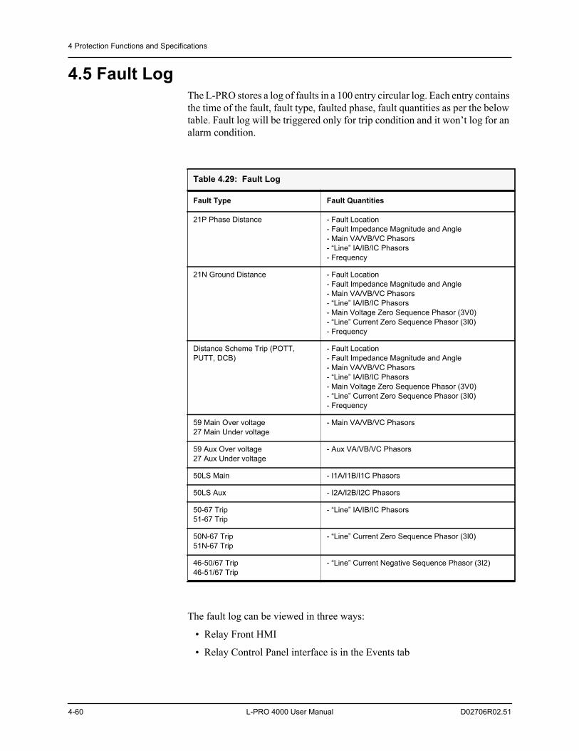
4 Protection Functions and Specifications
4-60 L-PRO 4000 User Manual D02706R02.51
4.5 Fault LogThe L-PRO stores a log of faults in a 100 entry circular log. Each entry contains the time of the fault, fault type, faulted phase, fault quantities as per the below table. Fault log will be triggered only for trip condition and it won’t log for an alarm condition.
The fault log can be viewed in three ways:
• Relay Front HMI
• Relay Control Panel interface is in the Events tab
Table 4.29: Fault Log
Fault Type Fault Quantities
21P Phase Distance - Fault Location- Fault Impedance Magnitude and Angle- Main VA/VB/VC Phasors- “Line” IA/IB/IC Phasors- Frequency
21N Ground Distance - Fault Location- Fault Impedance Magnitude and Angle- Main VA/VB/VC Phasors- “Line” IA/IB/IC Phasors- Main Voltage Zero Sequence Phasor (3V0)- “Line” Current Zero Sequence Phasor (3I0)- Frequency
Distance Scheme Trip (POTT, PUTT, DCB)
- Fault Location- Fault Impedance Magnitude and Angle- Main VA/VB/VC Phasors- “Line” IA/IB/IC Phasors- Main Voltage Zero Sequence Phasor (3V0)- “Line” Current Zero Sequence Phasor (3I0)- Frequency
59 Main Over voltage27 Main Under voltage
- Main VA/VB/VC Phasors
59 Aux Over voltage27 Aux Under voltage
- Aux VA/VB/VC Phasors
50LS Main - I1A/I1B/I1C Phasors
50LS Aux - I2A/I2B/I2C Phasors
50-67 Trip51-67 Trip
- “Line” IA/IB/IC Phasors
50N-67 Trip51N-67 Trip
- “Line” Current Zero Sequence Phasor (3I0)
46-50/67 Trip46-51/67 Trip
- “Line” Current Negative Sequence Phasor (3I2)
4 Protection Functions and Specifications
D02706R02.51 L-PRO 4000 User Manual 4-61
• 61850 SCADA protocol included in the L-PRO allow the SCADA client access to Trip event data

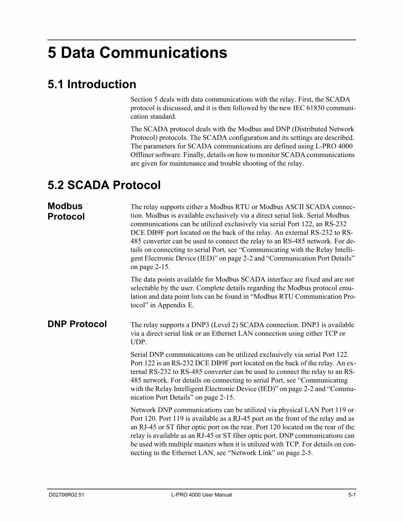
D02706R02.51 L-PRO 4000 User Manual 5-1
5 Data Communications
5.1 IntroductionSection 5 deals with data communications with the relay. First, the SCADA protocol is discussed, and it is then followed by the new IEC 61850 communi-cation standard.
The SCADA protocol deals with the Modbus and DNP (Distributed Network Protocol) protocols. The SCADA configuration and its settings are described. The parameters for SCADA communications are defined using L-PRO 4000 Offliner software. Finally, details on how to monitor SCADA communications are given for maintenance and trouble shooting of the relay.
5.2 SCADA ProtocolModbus Protocol
The relay supports either a Modbus RTU or Modbus ASCII SCADA connec-tion. Modbus is available exclusively via a direct serial link. Serial Modbus communications can be utilized exclusively via serial Port 122, an RS-232 DCE DB9F port located on the back of the relay. An external RS-232 to RS-485 converter can be used to connect the relay to an RS-485 network. For de-tails on connecting to serial Port, see “Communicating with the Relay Intelli-gent Electronic Device (IED)” on page 2-2 and “Communication Port Details” on page 2-15.
The data points available for Modbus SCADA interface are fixed and are not selectable by the user. Complete details regarding the Modbus protocol emu-lation and data point lists can be found in “Modbus RTU Communication Pro-tocol” in Appendix E.
DNP Protocol The relay supports a DNP3 (Level 2) SCADA connection. DNP3 is available via a direct serial link or an Ethernet LAN connection using either TCP or UDP.
Serial DNP communications can be utilized exclusively via serial Port 122. Port 122 is an RS-232 DCE DB9F port located on the back of the relay. An ex-ternal RS-232 to RS-485 converter can be used to connect the relay to an RS-485 network. For details on connecting to serial Port, see “Communicating with the Relay Intelligent Electronic Device (IED)” on page 2-2 and “Commu-nication Port Details” on page 2-15.
Network DNP communications can be utilized via physical LAN Port 119 or Port 120. Port 119 is available as a RJ-45 port on the front of the relay and as an RJ-45 or ST fiber optic port on the rear. Port 120 located on the rear of the relay is available as an RJ-45 or ST fiber optic port. DNP communications can be used with multiple masters when it is utilized with TCP. For details on con-necting to the Ethernet LAN, see “Network Link” on page 2-5.
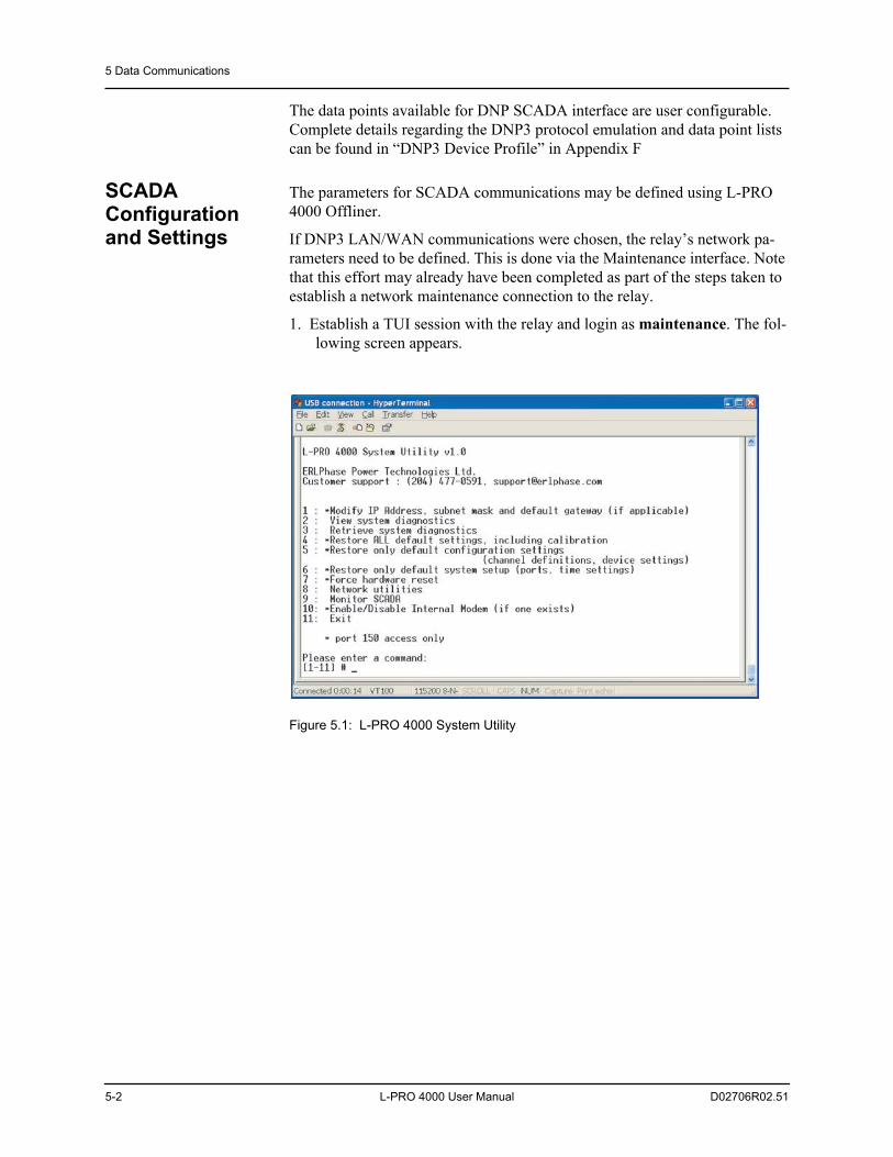
5 Data Communications
5-2 L-PRO 4000 User Manual D02706R02.51
The data points available for DNP SCADA interface are user configurable. Complete details regarding the DNP3 protocol emulation and data point lists can be found in “DNP3 Device Profile” in Appendix F
SCADA Configuration and Settings
The parameters for SCADA communications may be defined using L-PRO 4000 Offliner.
If DNP3 LAN/WAN communications were chosen, the relay’s network pa-rameters need to be defined. This is done via the Maintenance interface. Note that this effort may already have been completed as part of the steps taken to establish a network maintenance connection to the relay.
1. Establish a TUI session with the relay and login as maintenance. The fol-lowing screen appears.
Figure 5.1: L-PRO 4000 System Utility
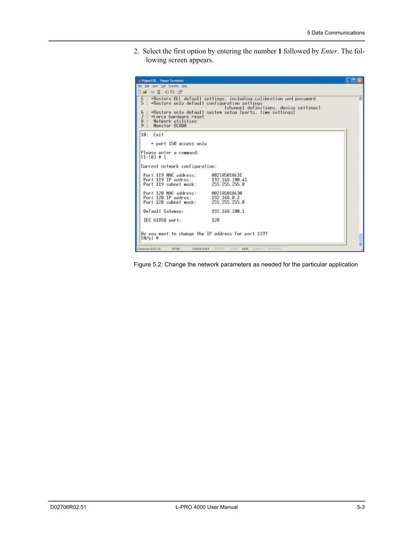
5 Data Communications
D02706R02.51 L-PRO 4000 User Manual 5-3
2. Select the first option by entering the number 1 followed by Enter. The fol-lowing screen appears.
Figure 5.2: Change the network parameters as needed for the particular application
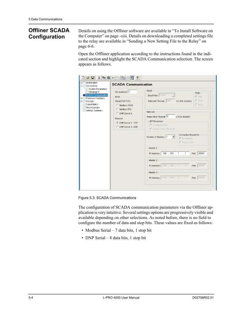
5 Data Communications
5-4 L-PRO 4000 User Manual D02706R02.51
Offliner SCADA Configuration
Details on using the Offliner software are available in “To Install Software on the Computer” on page -xiii. Details on downloading a completed settings file to the relay are available in “Sending a New Setting File to the Relay” on page 6-6.
Open the Offliner application according to the instructions found in the indi-cated section and highlight the SCADA Communication selection. The screen appears as follows.
Figure 5.3: SCADA Communications
The configuration of SCADA communication parameters via the Offliner ap-plication is very intuitive. Several settings options are progressively visible and available depending on other selections. As noted before, there is no field to configure the number of data and stop bits. These values are fixed as follows:
• Modbus Serial – 7 data bits, 1 stop bit
• DNP Serial – 8 data bits, 1 stop bit
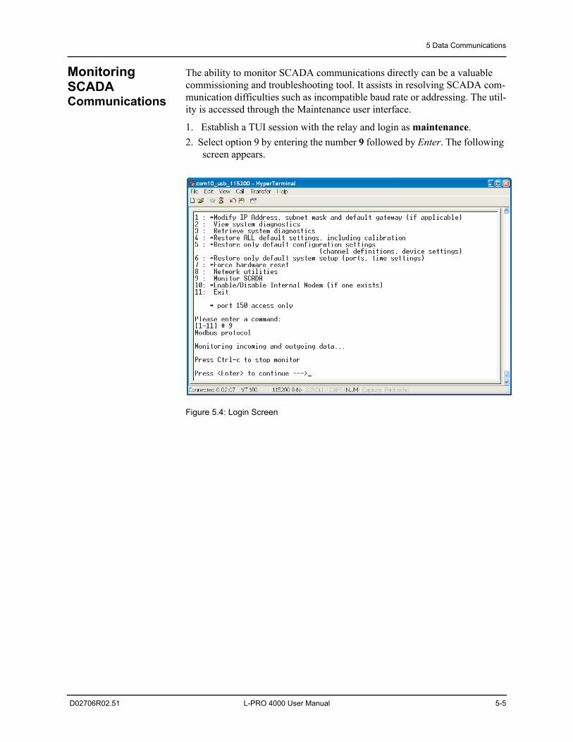
5 Data Communications
D02706R02.51 L-PRO 4000 User Manual 5-5
Monitoring SCADA Communications
The ability to monitor SCADA communications directly can be a valuable commissioning and troubleshooting tool. It assists in resolving SCADA com-munication difficulties such as incompatible baud rate or addressing. The util-ity is accessed through the Maintenance user interface.
1. Establish a TUI session with the relay and login as maintenance. 2. Select option 9 by entering the number 9 followed by Enter. The following
screen appears.
Figure 5.4: Login Screen
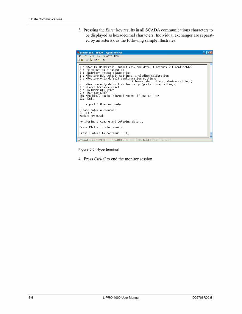
5 Data Communications
5-6 L-PRO 4000 User Manual D02706R02.51
3. Pressing the Enter key results in all SCADA communications characters to be displayed as hexadecimal characters. Individual exchanges are separat-ed by an asterisk as the following sample illustrates.
Figure 5.5: Hyperterminal
4. Press Ctrl-C to end the monitor session.
5 Data Communications
D02706R02.51 L-PRO 4000 User Manual 5-7
5.3 IEC 61850 CommunicationThe IEC 61850 Standard
The Smart Grid is transforming the electrical power industry by using digital technology to deliver electricity in a more intelligent, efficient and controlled way. Embedded control and communication devices are central to this trans-formation by adding intelligent automation to electrical networks.
The IEC 61850 standard defines a new protocol that permits substation equip-ment to communicate with each other. Like many other well-known manufac-turers, ERLPhase Power Technologies is dedicated to using IEC 61850-based devices that can be used as part of an open and versatile communications net-work for substation automation.
The IEC 61850 defines an Ethernet-based protocol used in substations for data communication. Substations implement a number of controllers for protection, measurement, detection, alarms, and monitoring. System implementation is of-ten slowed down by the fact that the controllers produced by different manu-facturers are incompatible, since they do not support the same communication protocols. The problems associated with this incompatibility are quite serious, and result in increased costs for protocol integration and system maintenance.
Implementation Details
The L-PRO 4000 conforms to IEC 61850-8-1, commonly referred to as Station Bus Protocol. Implementation includes the following documents (“IEC61850 Implementation” in Appendix N’ on page Appendix N-1):
• Protocol Implementation Conformance Statement
• Model Implementation Conformance Statement
• Tissues Conformance Statement
All configurable IEC61850 parameters are available via the Maintenance in-terface. Note that this effort may already have been completed as part of the steps taken to establish a network maintenance connection to the relay.
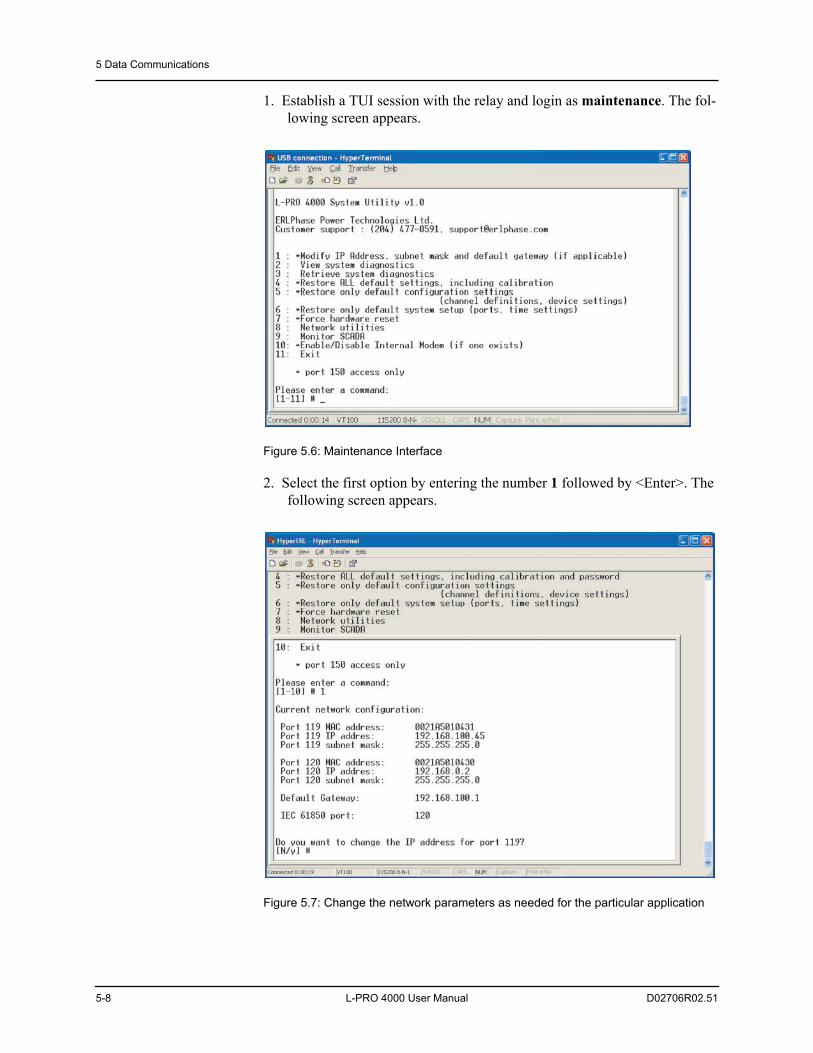
5 Data Communications
5-8 L-PRO 4000 User Manual D02706R02.51
1. Establish a TUI session with the relay and login as maintenance. The fol-lowing screen appears.
Figure 5.6: Maintenance Interface
2. Select the first option by entering the number 1 followed by <Enter>. The following screen appears.
Figure 5.7: Change the network parameters as needed for the particular application
5 Data Communications
D02706R02.51 L-PRO 4000 User Manual 5-9
Note that unit’s IP address can be used on the IEC61850 client side for unique unit identification instead of a physical device “PD Name”. The publisher con-figuration is fixed and defined in the ICD file and available for reading to any IEC61850 client. Subscriber functionality is also fixed and supported for the Virtual Inputs only.

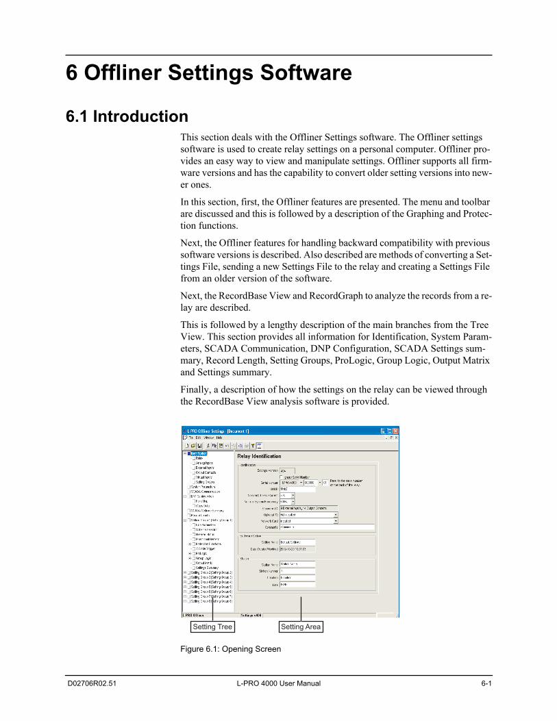
D02706R02.51 L-PRO 4000 User Manual 6-1
6 Offliner Settings Software
6.1 IntroductionThis section deals with the Offliner Settings software. The Offliner settings software is used to create relay settings on a personal computer. Offliner pro-vides an easy way to view and manipulate settings. Offliner supports all firm-ware versions and has the capability to convert older setting versions into new-er ones.
In this section, first, the Offliner features are presented. The menu and toolbar are discussed and this is followed by a description of the Graphing and Protec-tion functions.
Next, the Offliner features for handling backward compatibility with previous software versions is described. Also described are methods of converting a Set-tings File, sending a new Settings File to the relay and creating a Settings File from an older version of the software.
Next, the RecordBase View and RecordGraph to analyze the records from a re-lay are described.
This is followed by a lengthy description of the main branches from the Tree View. This section provides all information for Identification, System Param-eters, SCADA Communication, DNP Configuration, SCADA Settings sum-mary, Record Length, Setting Groups, ProLogic, Group Logic, Output Matrix and Settings summary.
Finally, a description of how the settings on the relay can be viewed through the RecordBase View analysis software is provided.
Figure 6.1: Opening Screen
Setting Tree Setting Area
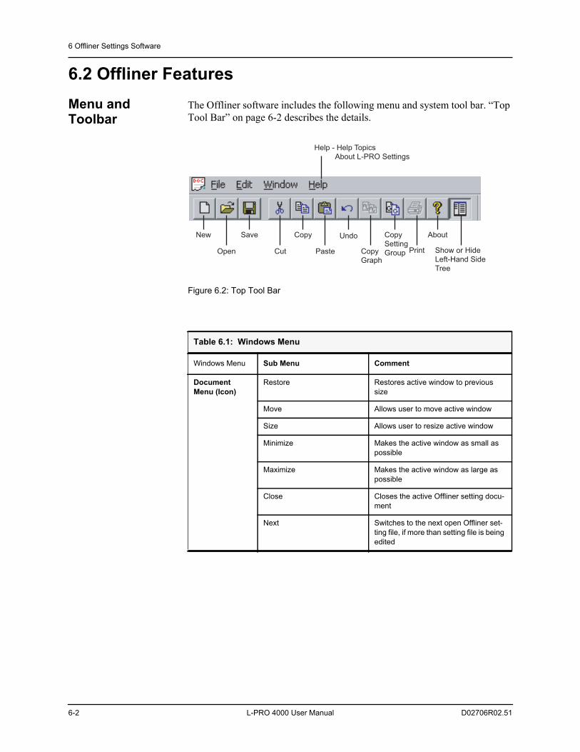
6 Offliner Settings Software
6-2 L-PRO 4000 User Manual D02706R02.51
6.2 Offliner FeaturesMenu and Toolbar
The Offliner software includes the following menu and system tool bar. “Top Tool Bar” on page 6-2 describes the details.
Figure 6.2: Top Tool Bar
Table 6.1: Windows Menu
Windows Menu Sub Menu Comment
Document Menu (Icon)
Restore Restores active window to previous size
Move Allows user to move active window
Size Allows user to resize active window
Minimize Makes the active window as small as possible
Maximize Makes the active window as large as possible
Close Closes the active Offliner setting docu-ment
Next Switches to the next open Offliner set-ting file, if more than setting file is being edited
Help - Help Topics
About L-PRO Settings
New Save Copy Undo About
Show or Hide
Left-Hand Side
Tree
Open Cut Paste Print
Copy
Setting
GroupCopy
Graph
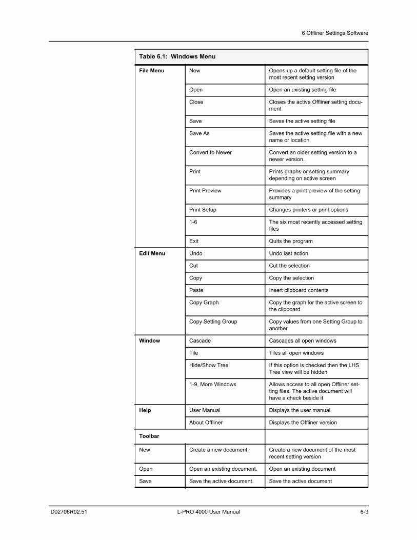
6 Offliner Settings Software
D02706R02.51 L-PRO 4000 User Manual 6-3
File Menu New Opens up a default setting file of the most recent setting version
Open Open an existing setting file
Close Closes the active Offliner setting docu-ment
Save Saves the active setting file
Save As Saves the active setting file with a new name or location
Convert to Newer Convert an older setting version to a newer version.
Print Prints graphs or setting summary depending on active screen
Print Preview Provides a print preview of the setting summary
Print Setup Changes printers or print options
1-6 The six most recently accessed setting files
Exit Quits the program
Edit Menu Undo Undo last action
Cut Cut the selection
Copy Copy the selection
Paste Insert clipboard contents
Copy Graph Copy the graph for the active screen to the clipboard
Copy Setting Group Copy values from one Setting Group to another
Window Cascade Cascades all open windows
Tile Tiles all open windows
Hide/Show Tree If this option is checked then the LHS Tree view will be hidden
1-9, More Windows Allows access to all open Offliner set-ting files. The active document will have a check beside it
Help User Manual Displays the user manual
About Offliner Displays the Offliner version
Toolbar
New Create a new document. Create a new document of the most recent setting version
Open Open an existing document. Open an existing document
Save Save the active document. Save the active document
Table 6.1: Windows Menu
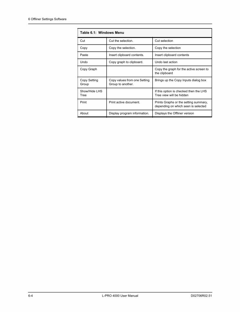
6 Offliner Settings Software
6-4 L-PRO 4000 User Manual D02706R02.51
Cut Cut the selection. Cut selection
Copy Copy the selection. Copy the selection
Paste Insert clipboard contents. Insert clipboard contents
Undo Copy graph to clipboard. Undo last action
Copy Graph Copy the graph for the active screen to the clipboard
Copy Setting Group
Copy values from one Setting Group to another.
Brings up the Copy Inputs dialog box
Show/Hide LHS Tree
If this option is checked then the LHS Tree view will be hidden
Print Print active document. Prints Graphs or the setting summary, depending on which seen is selected
About Display program information. Displays the Offliner version
Table 6.1: Windows Menu
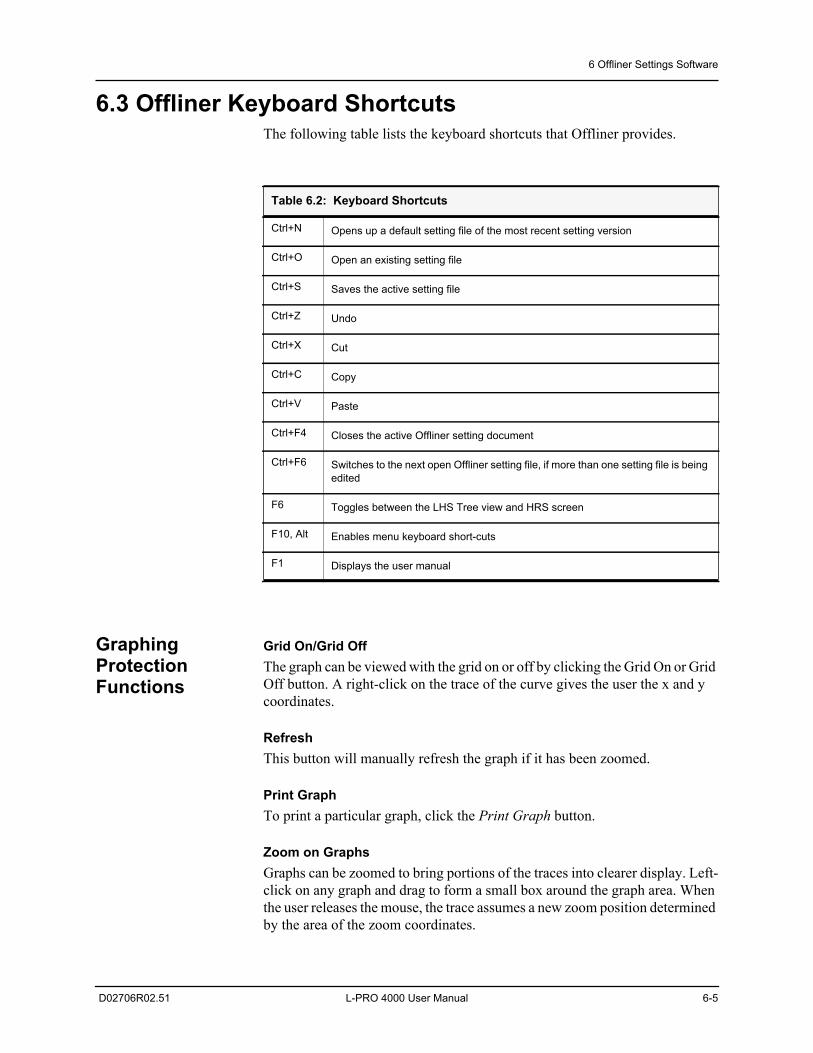
6 Offliner Settings Software
D02706R02.51 L-PRO 4000 User Manual 6-5
6.3 Offliner Keyboard ShortcutsThe following table lists the keyboard shortcuts that Offliner provides.
Graphing Protection Functions
Grid On/Grid OffThe graph can be viewed with the grid on or off by clicking the Grid On or Grid Off button. A right-click on the trace of the curve gives the user the x and y coordinates.
RefreshThis button will manually refresh the graph if it has been zoomed.
Print GraphTo print a particular graph, click the Print Graph button.
Zoom on GraphsGraphs can be zoomed to bring portions of the traces into clearer display. Left-click on any graph and drag to form a small box around the graph area. When the user releases the mouse, the trace assumes a new zoom position determined by the area of the zoom coordinates.
Table 6.2: Keyboard Shortcuts
Ctrl+N Opens up a default setting file of the most recent setting version
Ctrl+O Open an existing setting file
Ctrl+S Saves the active setting file
Ctrl+Z Undo
Ctrl+X Cut
Ctrl+C Copy
Ctrl+V Paste
Ctrl+F4 Closes the active Offliner setting document
Ctrl+F6 Switches to the next open Offliner setting file, if more than one setting file is being edited
F6 Toggles between the LHS Tree view and HRS screen
F10, Alt Enables menu keyboard short-cuts
F1 Displays the user manual
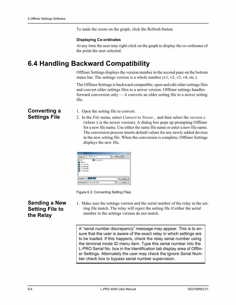
6 Offliner Settings Software
6-6 L-PRO 4000 User Manual D02706R02.51
To undo the zoom on the graph, click the Refresh button.
Displaying Co-ordinatesAt any time the user may right-click on the graph to display the co-ordinates of the point the user selected.
6.4 Handling Backward CompatibilityOffliner Settings displays the version number in the second pane on the bottom status bar. The settings version is a whole number (v1, v2, v3, v4, etc.).
The Offliner Settings is backward compatible; open and edit older settings files and convert older settings files to a newer version. Offliner settings handles forward conversion only — it converts an older setting file to a newer setting file.
Converting a Settings File
1. Open the setting file to convert. 2. In the File menu, select Convert to Newer... and then select the version x
(where x is the newer version). A dialog box pops up prompting Offliner for a new file name. Use either the same file name or enter a new file name. The conversion process inserts default values for any newly added devices in the new setting file. When the conversion is complete, Offliner Settings displays the new file.
Figure 6.3: Converting Setting Files
Sending a New Setting File to the Relay
1. Make sure the settings version and the serial number of the relay in the set-ting file match. The relay will reject the setting file if either the serial number or the settings version do not match.
A “serial number discrepancy” message may appear. This is to en-sure that the user is aware of the exact relay in which settings are to be loaded. If this happens, check the relay serial number using the terminal mode ID menu item. Type this serial number into the L-PRO Serial No. box in the Identification tab display area of Offlin-er Settings. Alternately the user may check the Ignore Serial Num-ber check box to bypass serial number supervision.
6 Offliner Settings Software
D02706R02.51 L-PRO 4000 User Manual 6-7
2. Check the serial number and the settings version of the relay. The Device Serial Number and Required Settings Version on the Identification screen indicate the serial number and the settings version of the relay.
Creating a Setting File from an Older Version
1. Offliner Settings displays a default setting file on start up showing the set-tings version in the bottom status bar. As an example L-PRO Offliner is shipped with a set of default sample files of older settings versions. These sample files are “v1 sample.lps”, “v2 sample.lps”, “v3 sample.lps”, etc. Each sample file contains default values of an older settings version. For a new installation these sample files are placed in the default directory C:\Program Files\ERLPhase\L-PRO Offliner Settings, or the user can choose the path during the Offliner software installation. If an older ver-sion of L-PRO Offliner was previously installed on the PC, then the default directory may be C:\Program Files\APT\L-PRO Offliner Settings. Open a sample file of the desired version. Use File/Save As to save the sample file to a new file name. Then edit the setting file and the serial number, save it and load it into the relay.
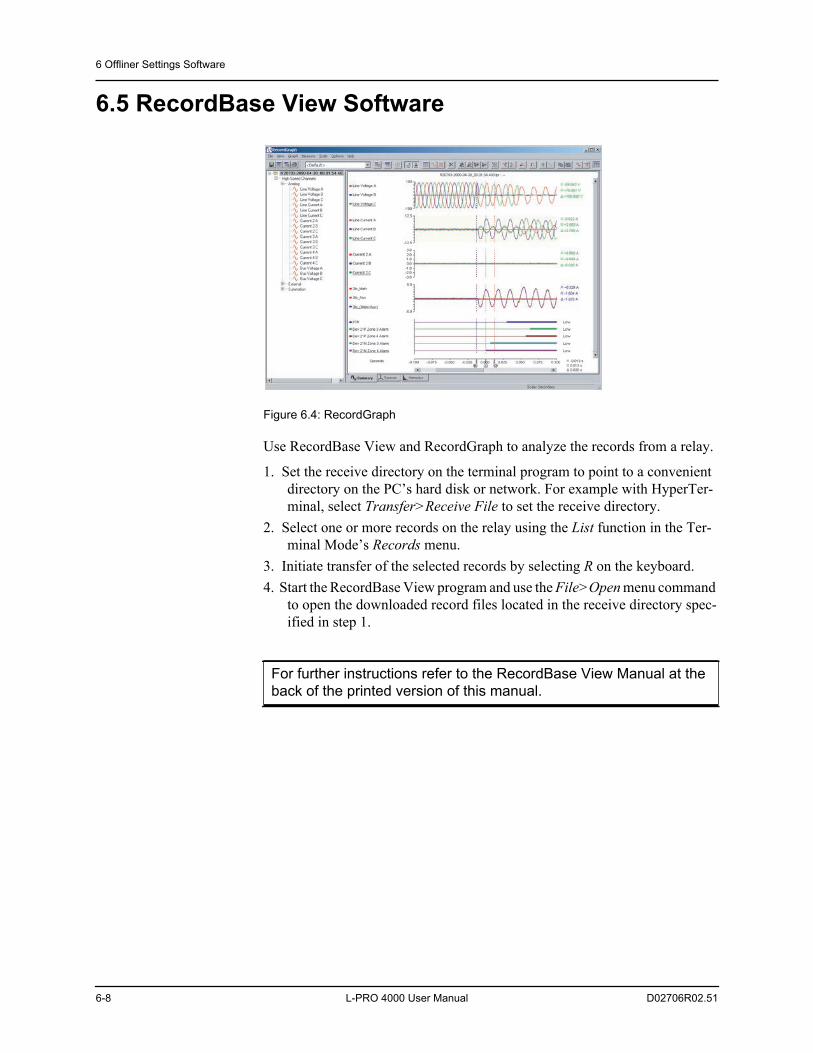
6 Offliner Settings Software
6-8 L-PRO 4000 User Manual D02706R02.51
6.5 RecordBase View Software
Figure 6.4: RecordGraph
Use RecordBase View and RecordGraph to analyze the records from a relay.
1. Set the receive directory on the terminal program to point to a convenient directory on the PC’s hard disk or network. For example with HyperTer-minal, select Transfer>Receive File to set the receive directory.
2. Select one or more records on the relay using the List function in the Ter-minal Mode’s Records menu.
3. Initiate transfer of the selected records by selecting R on the keyboard.4. Start the RecordBase View program and use the File>Open menu command
to open the downloaded record files located in the receive directory spec-ified in step 1.
For further instructions refer to the RecordBase View Manual at the back of the printed version of this manual.
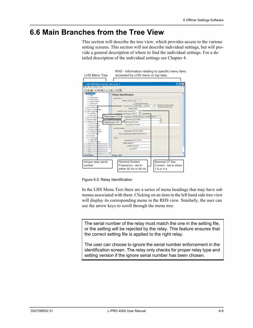
6 Offliner Settings Software
D02706R02.51 L-PRO 4000 User Manual 6-9
6.6 Main Branches from the Tree ViewThis section will describe the tree view, which provides access to the various setting screens. This section will not describe individual settings, but will pro-vide a general description of where to find the individual settings. For a de-tailed description of the individual settings see Chapter 4.
Figure 6.5: Relay Identification
In the LHS Menu Tree there are a series of menu headings that may have sub menus associated with them. Clicking on an item in the left hand side tree view will display its corresponding menu in the RHS view. Similarly, the user can use the arrow keys to scroll through the menu tree.
The serial number of the relay must match the one in the setting file, or the setting will be rejected by the relay. This feature ensures that the correct setting file is applied to the right relay.
The user can choose to ignore the serial number enforcement in the identification screen. The relay only checks for proper relay type and setting version if the ignore serial number has been chosen.
LHS Menu TreeRHS - Information relating to specific menu Item,accessed by LHS menu or top tabs.
Standard I/O
Optional I/O
Unique relay serialnumber
Nominal SystemFrequency - set toeither 50 Hz or 60 Hz
Nominal CT Sec.Current - set to either 1 A or 5 A
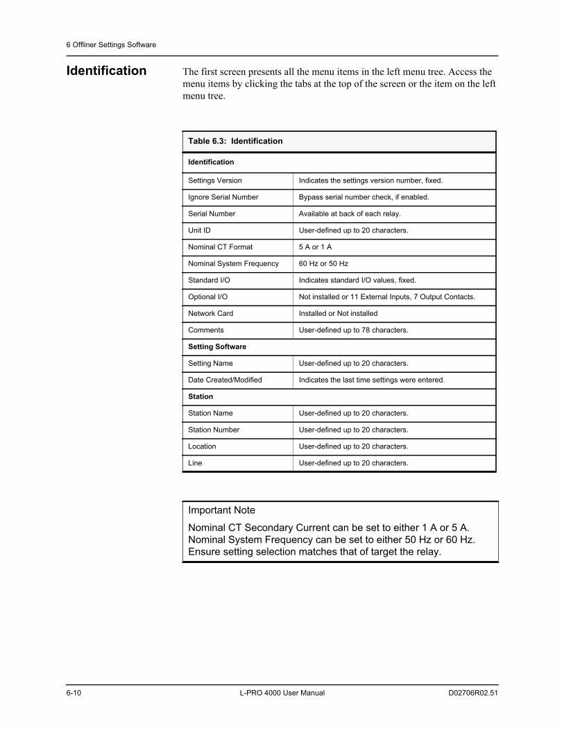
6 Offliner Settings Software
6-10 L-PRO 4000 User Manual D02706R02.51
Identification The first screen presents all the menu items in the left menu tree. Access the menu items by clicking the tabs at the top of the screen or the item on the left menu tree.
Table 6.3: Identification
Identification
Settings Version Indicates the settings version number, fixed.
Ignore Serial Number Bypass serial number check, if enabled.
Serial Number Available at back of each relay.
Unit ID User-defined up to 20 characters.
Nominal CT Format 5 A or 1 A
Nominal System Frequency 60 Hz or 50 Hz
Standard I/O Indicates standard I/O values, fixed.
Optional I/O Not installed or 11 External Inputs, 7 Output Contacts.
Network Card Installed or Not installed
Comments User-defined up to 78 characters.
Setting Software
Setting Name User-defined up to 20 characters.
Date Created/Modified Indicates the last time settings were entered.
Station
Station Name User-defined up to 20 characters.
Station Number User-defined up to 20 characters.
Location User-defined up to 20 characters.
Line User-defined up to 20 characters.
Important Note
Nominal CT Secondary Current can be set to either 1 A or 5 A.Nominal System Frequency can be set to either 50 Hz or 60 Hz.Ensure setting selection matches that of target the relay.
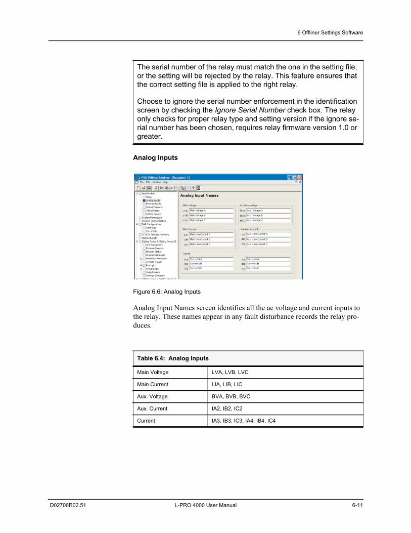
6 Offliner Settings Software
D02706R02.51 L-PRO 4000 User Manual 6-11
Analog Inputs
Figure 6.6: Analog Inputs
Analog Input Names screen identifies all the ac voltage and current inputs to the relay. These names appear in any fault disturbance records the relay pro-duces.
The serial number of the relay must match the one in the setting file, or the setting will be rejected by the relay. This feature ensures that the correct setting file is applied to the right relay.
Choose to ignore the serial number enforcement in the identification screen by checking the Ignore Serial Number check box. The relay only checks for proper relay type and setting version if the ignore se-rial number has been chosen, requires relay firmware version 1.0 or greater.
Table 6.4: Analog Inputs
Main Voltage LVA, LVB, LVC
Main Current LIA, LIB, LIC
Aux. Voltage BVA, BVB, BVC
Aux. Current IA2, IB2, IC2
Current IA3, IB3, IC3, IA4, IB4, IC4
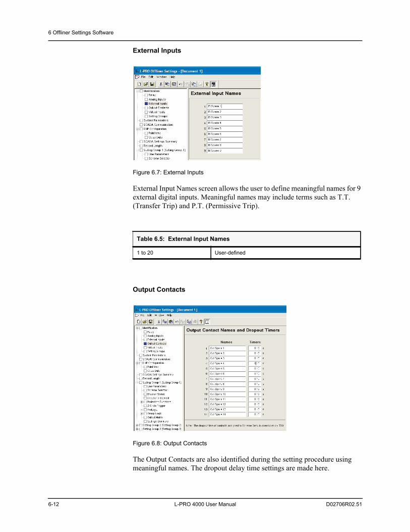
6 Offliner Settings Software
6-12 L-PRO 4000 User Manual D02706R02.51
External Inputs
Figure 6.7: External Inputs
External Input Names screen allows the user to define meaningful names for 9 external digital inputs. Meaningful names may include terms such as T.T. (Transfer Trip) and P.T. (Permissive Trip).
Output Contacts
Figure 6.8: Output Contacts
The Output Contacts are also identified during the setting procedure using meaningful names. The dropout delay time settings are made here.
Table 6.5: External Input Names
1 to 20 User-defined
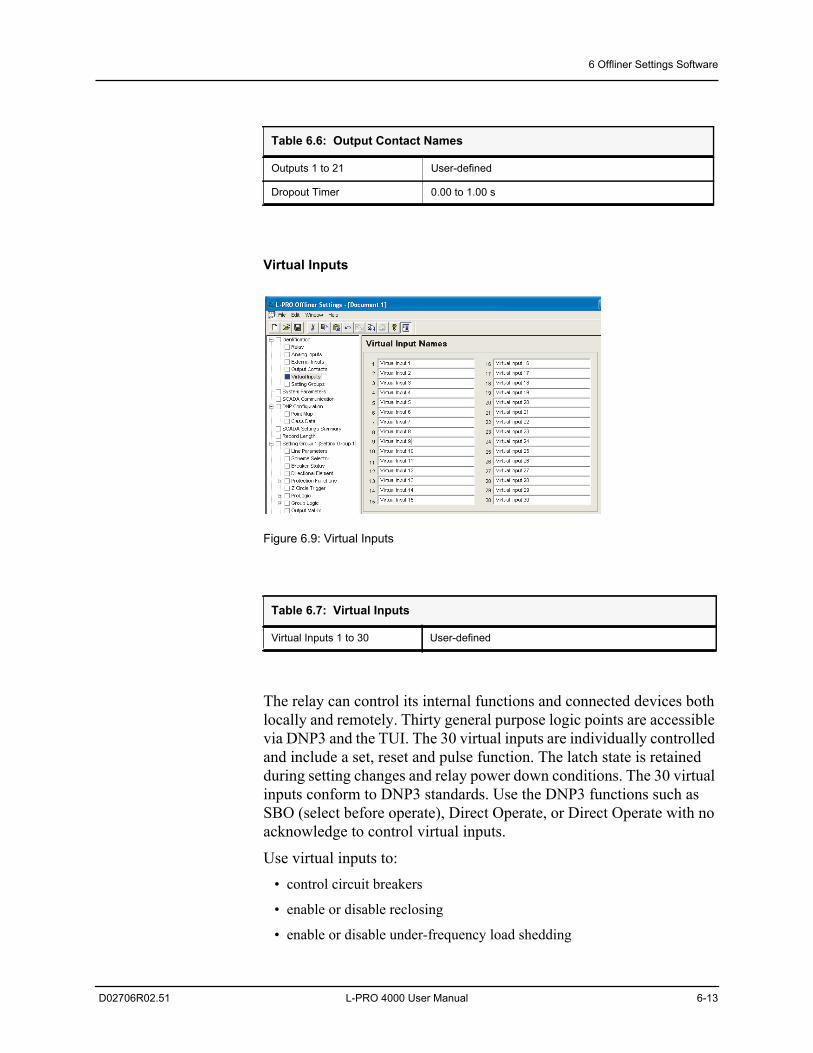
6 Offliner Settings Software
D02706R02.51 L-PRO 4000 User Manual 6-13
Virtual Inputs
Figure 6.9: Virtual Inputs
The relay can control its internal functions and connected devices both locally and remotely. Thirty general purpose logic points are accessible via DNP3 and the TUI. The 30 virtual inputs are individually controlled and include a set, reset and pulse function. The latch state is retained during setting changes and relay power down conditions. The 30 virtual inputs conform to DNP3 standards. Use the DNP3 functions such as SBO (select before operate), Direct Operate, or Direct Operate with no acknowledge to control virtual inputs.
Use virtual inputs to: • control circuit breakers
• enable or disable reclosing
• enable or disable under-frequency load shedding
Table 6.6: Output Contact Names
Outputs 1 to 21 User-defined
Dropout Timer 0.00 to 1.00 s
Table 6.7: Virtual Inputs
Virtual Inputs 1 to 30 User-defined
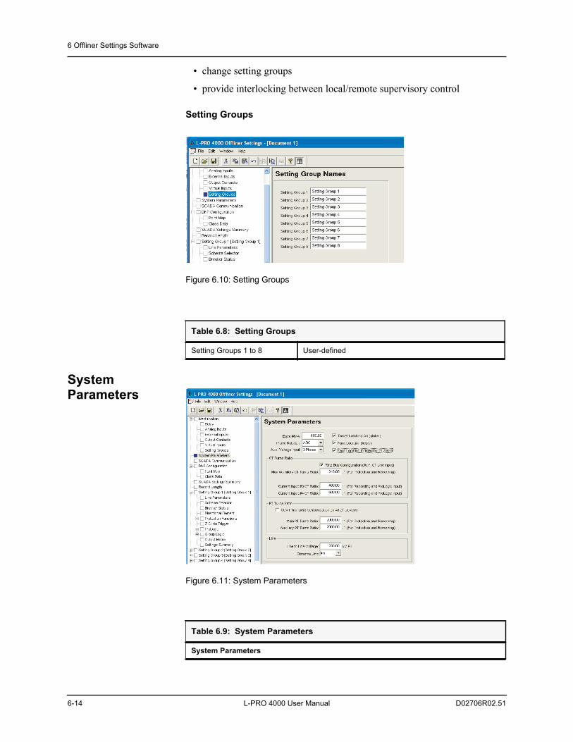
6 Offliner Settings Software
6-14 L-PRO 4000 User Manual D02706R02.51
• change setting groups
• provide interlocking between local/remote supervisory control
Setting Groups
Figure 6.10: Setting Groups
System Parameters
Figure 6.11: System Parameters
Table 6.8: Setting Groups
Setting Groups 1 to 8 User-defined
Table 6.9: System Parameters
System Parameters
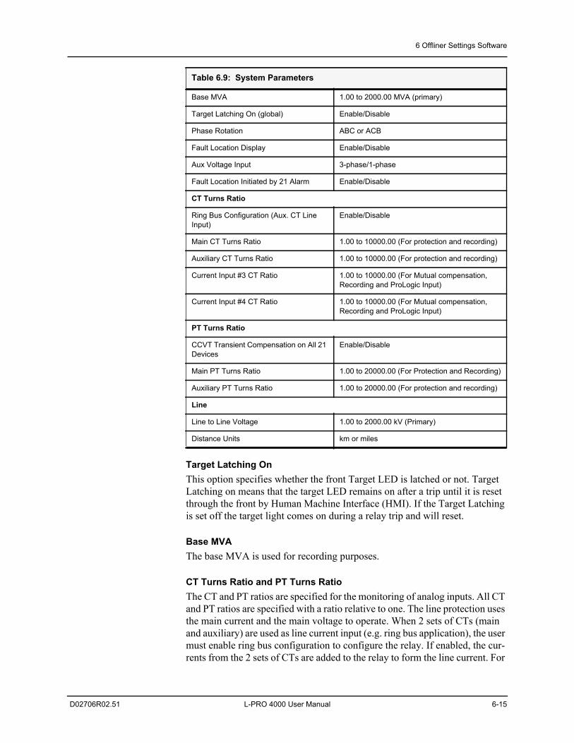
6 Offliner Settings Software
D02706R02.51 L-PRO 4000 User Manual 6-15
Target Latching OnThis option specifies whether the front Target LED is latched or not. Target Latching on means that the target LED remains on after a trip until it is reset through the front by Human Machine Interface (HMI). If the Target Latching is set off the target light comes on during a relay trip and will reset.
Base MVA The base MVA is used for recording purposes.
CT Turns Ratio and PT Turns RatioThe CT and PT ratios are specified for the monitoring of analog inputs. All CT and PT ratios are specified with a ratio relative to one. The line protection uses the main current and the main voltage to operate. When 2 sets of CTs (main and auxiliary) are used as line current input (e.g. ring bus application), the user must enable ring bus configuration to configure the relay. If enabled, the cur-rents from the 2 sets of CTs are added to the relay to form the line current. For
Base MVA 1.00 to 2000.00 MVA (primary)
Target Latching On (global) Enable/Disable
Phase Rotation ABC or ACB
Fault Location Display Enable/Disable
Aux Voltage Input 3-phase/1-phase
Fault Location Initiated by 21 Alarm Enable/Disable
CT Turns Ratio
Ring Bus Configuration (Aux. CT Line Input)
Enable/Disable
Main CT Turns Ratio 1.00 to 10000.00 (For protection and recording)
Auxiliary CT Turns Ratio 1.00 to 10000.00 (For protection and recording)
Current Input #3 CT Ratio 1.00 to 10000.00 (For Mutual compensation, Recording and ProLogic Input)
Current Input #4 CT Ratio 1.00 to 10000.00 (For Mutual compensation, Recording and ProLogic Input)
PT Turns Ratio
CCVT Transient Compensation on All 21 Devices
Enable/Disable
Main PT Turns Ratio 1.00 to 20000.00 (For Protection and Recording)
Auxiliary PT Turns Ratio 1.00 to 20000.00 (For protection and recording)
Line
Line to Line Voltage 1.00 to 2000.00 kV (Primary)
Distance Units km or miles
Table 6.9: System Parameters
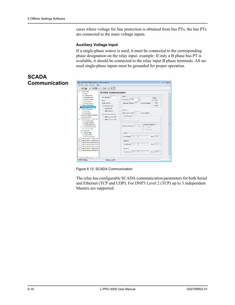
6 Offliner Settings Software
6-16 L-PRO 4000 User Manual D02706R02.51
cases where voltage for line protection is obtained from bus PTs, the bus PTs are connected to the main voltage inputs.
Auxiliary Voltage InputIf a single-phase source is used, it must be connected to the corresponding phase designation on the relay input. example: If only a B phase bus PT is available, it should be connected to the relay input B phase terminals. All un-used single-phase inputs must be grounded for proper operation.
SCADA Communication
Figure 6.12: SCADA Communication
The relay has configurable SCADA communication parameters for both Serial and Ethernet (TCP and UDP). For DNP3 Level 2 (TCP) up to 3 independent Masters are supported.
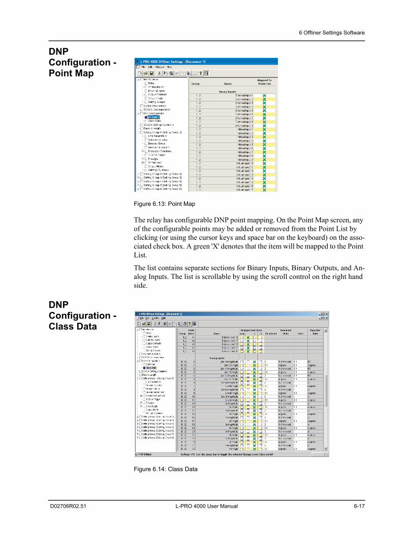
6 Offliner Settings Software
D02706R02.51 L-PRO 4000 User Manual 6-17
DNP Configuration - Point Map
Figure 6.13: Point Map
The relay has configurable DNP point mapping. On the Point Map screen, any of the configurable points may be added or removed from the Point List by clicking (or using the cursor keys and space bar on the keyboard) on the asso-ciated check box. A green 'X' denotes that the item will be mapped to the Point List.
The list contains separate sections for Binary Inputs, Binary Outputs, and An-alog Inputs. The list is scrollable by using the scroll control on the right hand side.
DNP Configuration - Class Data
Figure 6.14: Class Data
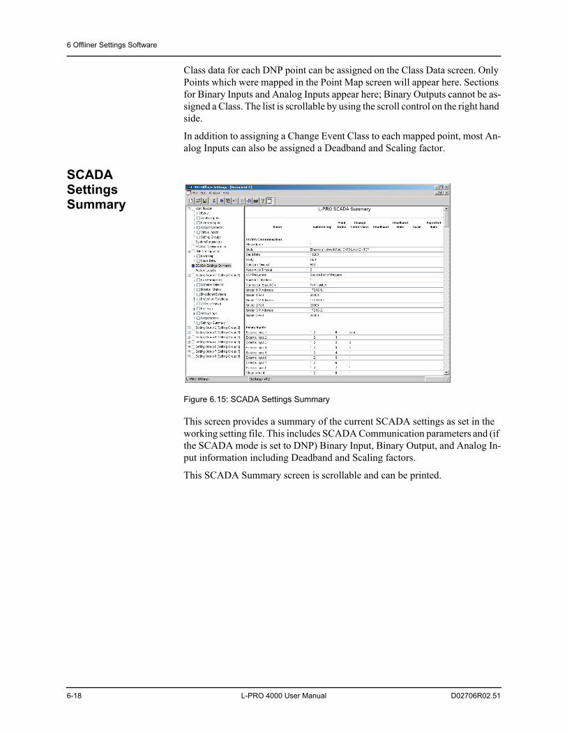
6 Offliner Settings Software
6-18 L-PRO 4000 User Manual D02706R02.51
Class data for each DNP point can be assigned on the Class Data screen. Only Points which were mapped in the Point Map screen will appear here. Sections for Binary Inputs and Analog Inputs appear here; Binary Outputs cannot be as-signed a Class. The list is scrollable by using the scroll control on the right hand side.
In addition to assigning a Change Event Class to each mapped point, most An-alog Inputs can also be assigned a Deadband and Scaling factor.
SCADA Settings Summary
Figure 6.15: SCADA Settings Summary
This screen provides a summary of the current SCADA settings as set in the working setting file. This includes SCADA Communication parameters and (if the SCADA mode is set to DNP) Binary Input, Binary Output, and Analog In-put information including Deadband and Scaling factors.
This SCADA Summary screen is scrollable and can be printed.
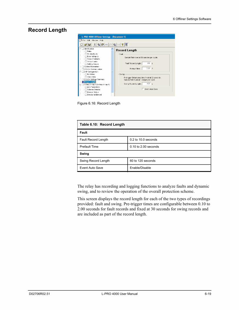
6 Offliner Settings Software
D02706R02.51 L-PRO 4000 User Manual 6-19
Record Length
Figure 6.16: Record Length
The relay has recording and logging functions to analyze faults and dynamic swing, and to review the operation of the overall protection scheme.
This screen displays the record length for each of the two types of recordings provided: fault and swing. Pre-trigger times are configurable between 0.10 to 2.00 seconds for fault records and fixed at 30 seconds for swing records and are included as part of the record length.
Table 6.10: Record Length
Fault
Fault Record Length 0.2 to 10.0 seconds
Prefault Time 0.10 to 2.00 seconds
Swing
Swing Record Length 60 to 120 seconds
Event Auto Save Enable/Disable
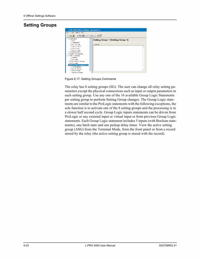
6 Offliner Settings Software
6-20 L-PRO 4000 User Manual D02706R02.51
Setting Groups
Figure 6.17: Setting Groups Comments
The relay has 8 setting groups (SG). The user can change all relay setting pa-rameters except the physical connections such as input or output parameters in each setting group. Use any one of the 16 available Group Logic Statements per setting group to perform Setting Group changes. The Group Logic state-ments are similar to the ProLogic statements with the following exceptions, the sole function is to activate one of the 8 setting groups and the processing is in a slower half second cycle. Group Logic inputs statements can be driven from ProLogic or any external input or virtual input or from previous Group Logic statements. Each Group Logic statement includes 5 inputs (with Boolean state-ments), one latch state and one pickup delay timer. View the active setting group (ASG) from the Terminal Mode, from the front panel or from a record stored by the relay (the active setting group is stored with the record).
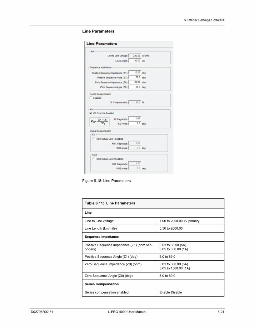
6 Offliner Settings Software
D02706R02.51 L-PRO 4000 User Manual 6-21
Line Parameters
Figure 6.18: Line Parameters
Table 6.11: Line Parameters
Line
Line to Line voltage 1.00 to 2000.00 kV primary
Line Length (km/mile) 0.50 to 2000.00
Sequence Impedance
Positive Sequence Impedance (Z1) (ohm sec-ondary)
0.01 to 66.00 (5A)0.05 to 330.00 (1A)
Positive Sequence Angle (Z1) (deg) 5.0 to 89.0
Zero Sequence Impedance (Z0) (ohm) 0.01 to 300.00 (5A)0.05 to 1500.00 (1A)
Zero Sequence Angle (Z0) (deg) 5.0 to 89.0
Series Compensation
Series compensation enabled Enable Disable
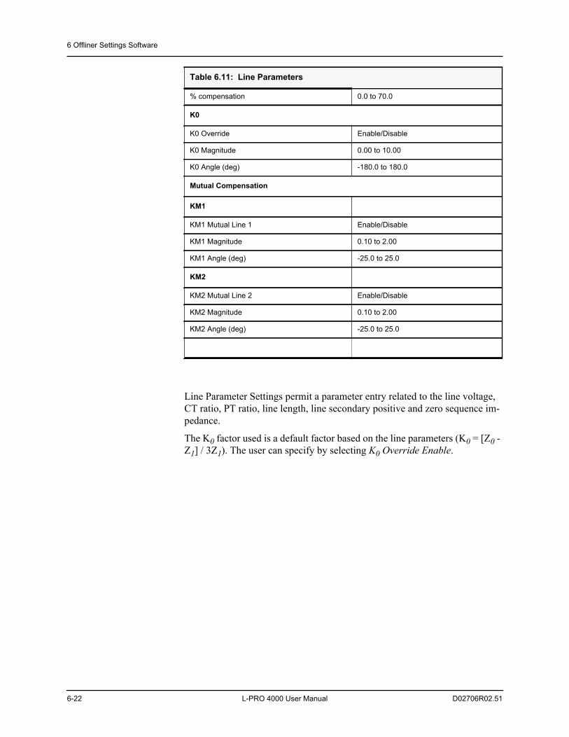
6 Offliner Settings Software
6-22 L-PRO 4000 User Manual D02706R02.51
Line Parameter Settings permit a parameter entry related to the line voltage, CT ratio, PT ratio, line length, line secondary positive and zero sequence im-pedance.
The K0 factor used is a default factor based on the line parameters (K0 = [Z0 - Z1] / 3Z1). The user can specify by selecting K0 Override Enable.
% compensation 0.0 to 70.0
K0
K0 Override Enable/Disable
K0 Magnitude 0.00 to 10.00
K0 Angle (deg) -180.0 to 180.0
Mutual Compensation
KM1
KM1 Mutual Line 1 Enable/Disable
KM1 Magnitude 0.10 to 2.00
KM1 Angle (deg) -25.0 to 25.0
KM2
KM2 Mutual Line 2 Enable/Disable
KM2 Magnitude 0.10 to 2.00
KM2 Angle (deg) -25.0 to 25.0
Table 6.11: Line Parameters
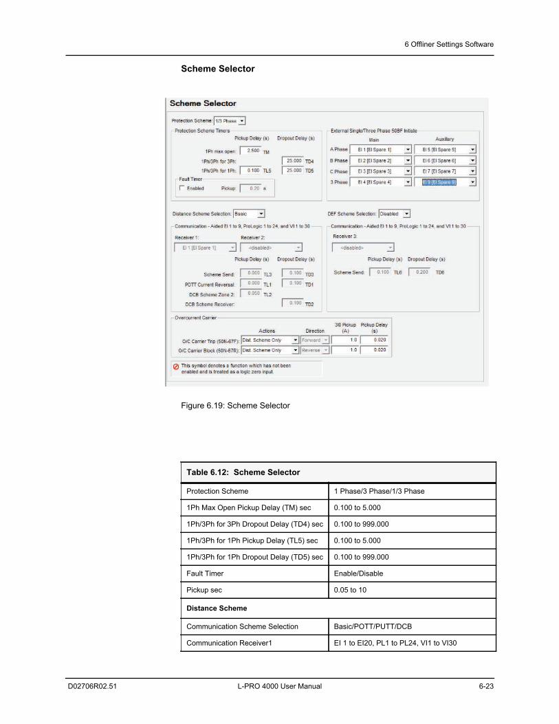
6 Offliner Settings Software
D02706R02.51 L-PRO 4000 User Manual 6-23
Scheme Selector
Figure 6.19: Scheme Selector
Table 6.12: Scheme Selector
Protection Scheme 1 Phase/3 Phase/1/3 Phase
1Ph Max Open Pickup Delay (TM) sec 0.100 to 5.000
1Ph/3Ph for 3Ph Dropout Delay (TD4) sec 0.100 to 999.000
1Ph/3Ph for 1Ph Pickup Delay (TL5) sec 0.100 to 5.000
1Ph/3Ph for 1Ph Dropout Delay (TD5) sec 0.100 to 999.000
Fault Timer Enable/Disable
Pickup sec 0.05 to 10
Distance Scheme
Communication Scheme Selection Basic/POTT/PUTT/DCB
Communication Receiver1 EI 1 to EI20, PL1 to PL24, VI1 to VI30
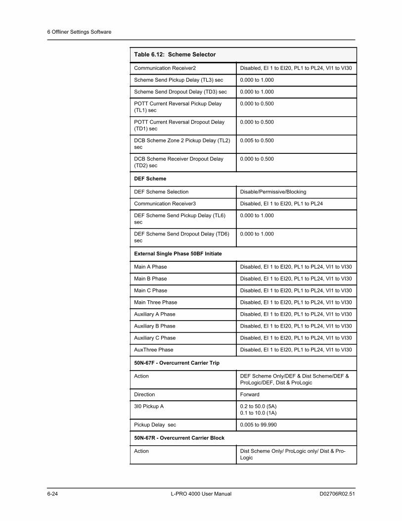
6 Offliner Settings Software
6-24 L-PRO 4000 User Manual D02706R02.51
Communication Receiver2 Disabled, EI 1 to EI20, PL1 to PL24, VI1 to VI30
Scheme Send Pickup Delay (TL3) sec 0.000 to 1.000
Scheme Send Dropout Delay (TD3) sec 0.000 to 1.000
POTT Current Reversal Pickup Delay (TL1) sec
0.000 to 0.500
POTT Current Reversal Dropout Delay (TD1) sec
0.000 to 0.500
DCB Scheme Zone 2 Pickup Delay (TL2) sec
0.005 to 0.500
DCB Scheme Receiver Dropout Delay (TD2) sec
0.000 to 0.500
DEF Scheme
DEF Scheme Selection Disable/Permissive/Blocking
Communication Receiver3 Disabled, EI 1 to EI20, PL1 to PL24
DEF Scheme Send Pickup Delay (TL6) sec
0.000 to 1.000
DEF Scheme Send Dropout Delay (TD6) sec
0.000 to 1.000
External Single Phase 50BF Initiate
Main A Phase Disabled, EI 1 to EI20, PL1 to PL24, VI1 to VI30
Main B Phase Disabled, EI 1 to EI20, PL1 to PL24, VI1 to VI30
Main C Phase Disabled, EI 1 to EI20, PL1 to PL24, VI1 to VI30
Main Three Phase Disabled, EI 1 to EI20, PL1 to PL24, VI1 to VI30
Auxiliary A Phase Disabled, EI 1 to EI20, PL1 to PL24, VI1 to VI30
Auxiliary B Phase Disabled, EI 1 to EI20, PL1 to PL24, VI1 to VI30
Auxiliary C Phase Disabled, EI 1 to EI20, PL1 to PL24, VI1 to VI30
AuxThree Phase Disabled, EI 1 to EI20, PL1 to PL24, VI1 to VI30
50N-67F - Overcurrent Carrier Trip
Action DEF Scheme Only/DEF & Dist Scheme/DEF & ProLogic/DEF, Dist & ProLogic
Direction Forward
3I0 Pickup A 0.2 to 50.0 (5A)0.1 to 10.0 (1A)
Pickup Delay sec 0.005 to 99.990
50N-67R - Overcurrent Carrier Block
Action Dist Scheme Only/ ProLogic only/ Dist & Pro-Logic
Table 6.12: Scheme Selector
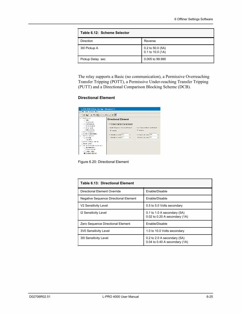
6 Offliner Settings Software
D02706R02.51 L-PRO 4000 User Manual 6-25
The relay supports a Basic (no communication), a Permissive Overreaching Transfer Tripping (POTT), a Permissive Under-reaching Transfer Tripping (PUTT) and a Directional Comparison Blocking Scheme (DCB).
Directional Element
Figure 6.20: Directional Element
Direction Reverse
3I0 Pickup A 0.2 to 50.0 (5A)0.1 to 10.0 (1A)
Pickup Delay sec 0.005 to 99.990
Table 6.13: Directional Element
Directional Element Override Enable/Disable
Negative Sequence Directional Element Enable/Disable
V2 Sensitivity Level 0.5 to 5.0 Volts secondary
I2 Sensitivity Level 0.1 to 1.0 A secondary (5A)0.02 to 0.20 A secondary (1A)
Zero Sequence Directional Element Enable/Disable
3V0 Sensitivity Level 1.0 to 10.0 Volts secondary
3I0 Sensitivity Level 0.2 to 2.0 A secondary (5A)0.04 to 0.40 A secondary (1A)
Table 6.12: Scheme Selector
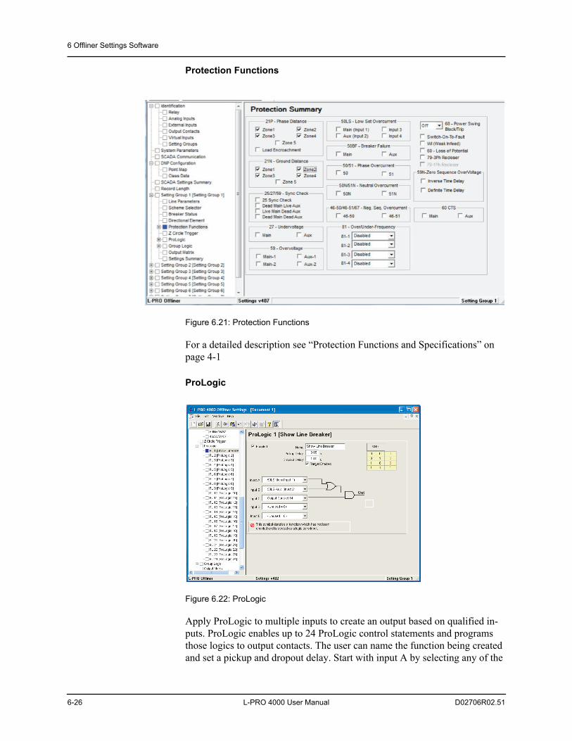
6 Offliner Settings Software
6-26 L-PRO 4000 User Manual D02706R02.51
Protection Functions
Figure 6.21: Protection Functions
For a detailed description see “Protection Functions and Specifications” on page 4-1
ProLogic
Figure 6.22: ProLogic
Apply ProLogic to multiple inputs to create an output based on qualified in-puts. ProLogic enables up to 24 ProLogic control statements and programs those logics to output contacts. The user can name the function being created and set a pickup and dropout delay. Start with input A by selecting any of the
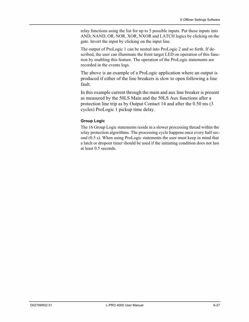
6 Offliner Settings Software
D02706R02.51 L-PRO 4000 User Manual 6-27
relay functions using the list for up to 5 possible inputs. Put these inputs into AND, NAND, OR, NOR, XOR, NXOR and LATCH logics by clicking on the gate. Invert the input by clicking on the input line.
The output of ProLogic 1 can be nested into ProLogic 2 and so forth. If de-scribed, the user can illuminate the front target LED on operation of this func-tion by enabling this feature. The operation of the ProLogic statements are recorded in the events logs.
The above is an example of a ProLogic application where an output is produced if either of the line breakers is slow to open following a line fault.
In this example current through the main and aux line breaker is present as measured by the 50LS Main and the 50LS Aux functions after a protection line trip as by Output Contact 14 and after the 0.50 ms (3 cycles) ProLogic 1 pickup time delay.
Group LogicThe 16 Group Logic statements reside in a slower processing thread within the relay protection algorithms. The processing cycle happens once every half sec-ond (0.5 s). When using ProLogic statements the user must keep in mind that a latch or dropout timer should be used if the initiating condition does not last at least 0.5 seconds.
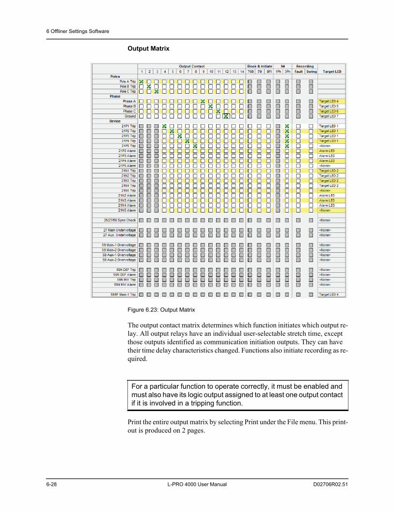
6 Offliner Settings Software
6-28 L-PRO 4000 User Manual D02706R02.51
Output Matrix
Figure 6.23: Output Matrix
The output contact matrix determines which function initiates which output re-lay. All output relays have an individual user-selectable stretch time, except those outputs identified as communication initiation outputs. They can have their time delay characteristics changed. Functions also initiate recording as re-quired.
Print the entire output matrix by selecting Print under the File menu. This print-out is produced on 2 pages.
For a particular function to operate correctly, it must be enabled and must also have its logic output assigned to at least one output contact if it is involved in a tripping function.
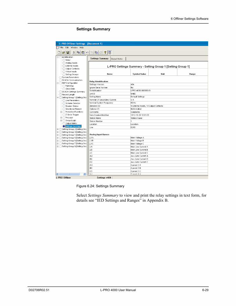
6 Offliner Settings Software
D02706R02.51 L-PRO 4000 User Manual 6-29
Settings Summary
Figure 6.24: Settings Summary
Select Settings Summary to view and print the relay settings in text form, for details see “IED Settings and Ranges” in Appendix B.
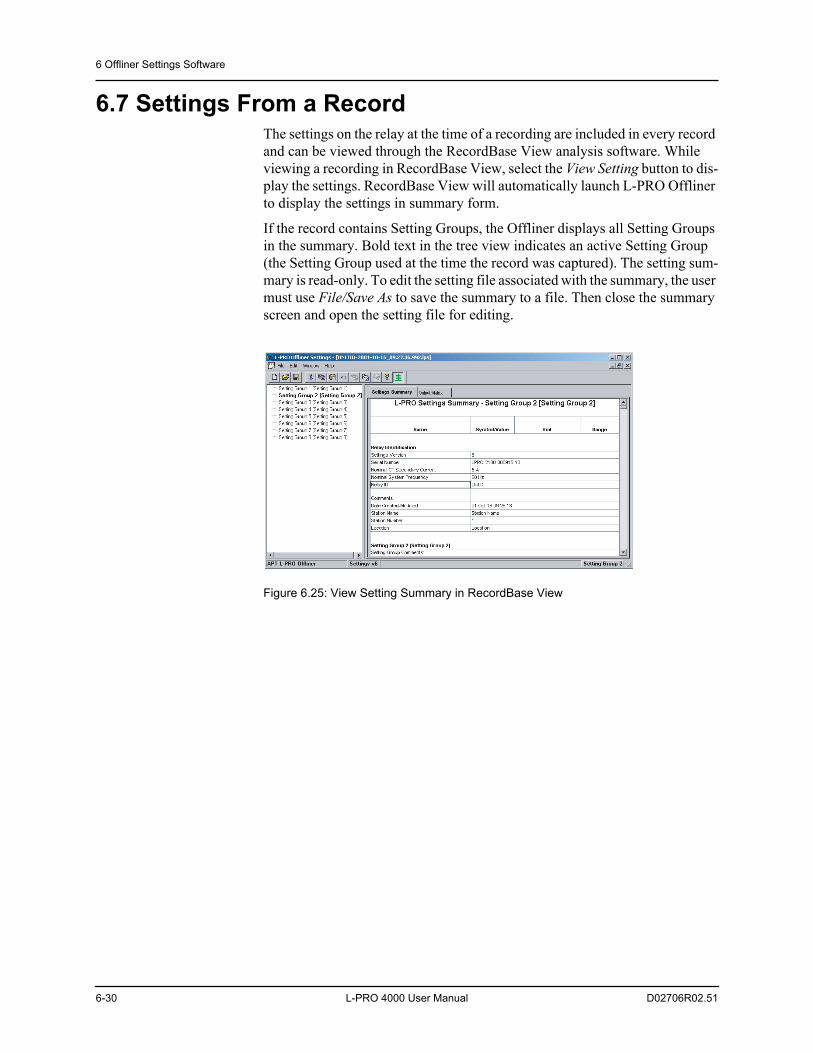
6 Offliner Settings Software
6-30 L-PRO 4000 User Manual D02706R02.51
6.7 Settings From a RecordThe settings on the relay at the time of a recording are included in every record and can be viewed through the RecordBase View analysis software. While viewing a recording in RecordBase View, select the View Setting button to dis-play the settings. RecordBase View will automatically launch L-PRO Offliner to display the settings in summary form.
If the record contains Setting Groups, the Offliner displays all Setting Groups in the summary. Bold text in the tree view indicates an active Setting Group (the Setting Group used at the time the record was captured). The setting sum-mary is read-only. To edit the setting file associated with the summary, the user must use File/Save As to save the summary to a file. Then close the summary screen and open the setting file for editing.
Figure 6.25: View Setting Summary in RecordBase View
D02706R02.51 L-PRO 4000 User Manual 7-1
7 Acceptance/Protection Function Test Guide
7.1 IntroductionThe acceptance test section is a guide for testing any and all protection ele-ments in the relay. These tests should be performed upon first delivery of the relay, prior to applying in-service settings. Once in-service settings are applied, ERLPhase recommends that the user test enabled functions to ensure the de-signed application is fulfilled.
This section deals with the Acceptance Testing and the L-PRO Acceptance Test Procedure.
First, the acceptance testing describes the test equipment requirements, calibra-tion methods, testing the external inputs and testing the output relay contacts.
Next, a step-by-step test procedure for testing all the relay devices is outlined.
7.2 Acceptance TestingERLPhase relays are fully tested before leaving the factory. A visual inspec-tion of the relay and its packaging is recommended on receipt to ensure the re-lay was not damaged during shipping.
Generally an analog metering check, as well as testing the I/O (External Inputs and Output Contacts) is sufficient to ensure the functionality of the relay. Fur-ther tests can be performed on delivery and acceptance of the purchaser’s op-tion according to the published relay specifications in “IED Settings and Ranges” in Appendix B.
Test Equipment Requirements
• 3 ac voltage sources (variable frequency capability)
• 3 ac current sources
• 1 ohmmeter
• 1 - 125 Vdc test supply
The electronics in the relay contain static sensitive devices and are not user-serviceable. If the front of the relay is opened for any reason exposing the electronics, take extreme care to ensure that the user and the relay are solidly grounded.
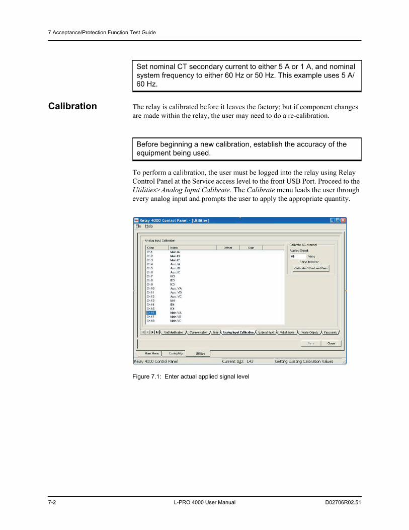
7 Acceptance/Protection Function Test Guide
7-2 L-PRO 4000 User Manual D02706R02.51
Calibration The relay is calibrated before it leaves the factory; but if component changes are made within the relay, the user may need to do a re-calibration.
To perform a calibration, the user must be logged into the relay using Relay Control Panel at the Service access level to the front USB Port. Proceed to the Utilities>Analog Input Calibrate. The Calibrate menu leads the user through every analog input and prompts the user to apply the appropriate quantity.
Figure 7.1: Enter actual applied signal level
Set nominal CT secondary current to either 5 A or 1 A, and nominal system frequency to either 60 Hz or 50 Hz. This example uses 5 A/60 Hz.
Before beginning a new calibration, establish the accuracy of the equipment being used.
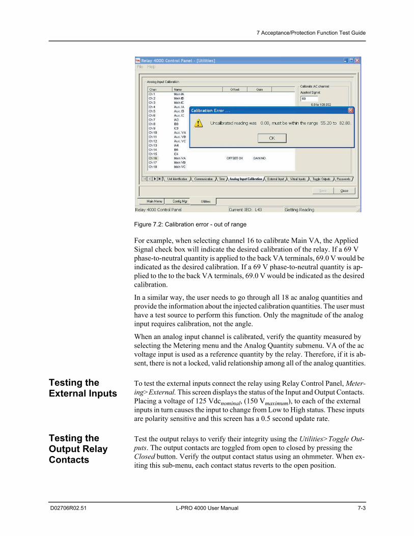
7 Acceptance/Protection Function Test Guide
D02706R02.51 L-PRO 4000 User Manual 7-3
Figure 7.2: Calibration error - out of range
For example, when selecting channel 16 to calibrate Main VA, the Applied Signal check box will indicate the desired calibration of the relay. If a 69 V phase-to-neutral quantity is applied to the back VA terminals, 69.0 V would be indicated as the desired calibration. If a 69 V phase-to-neutral quantity is ap-plied to the to the back VA terminals, 69.0 V would be indicated as the desired calibration.
In a similar way, the user needs to go through all 18 ac analog quantities and provide the information about the injected calibration quantities. The user must have a test source to perform this function. Only the magnitude of the analog input requires calibration, not the angle.
When an analog input channel is calibrated, verify the quantity measured by selecting the Metering menu and the Analog Quantity submenu. VA of the ac voltage input is used as a reference quantity by the relay. Therefore, if it is ab-sent, there is not a locked, valid relationship among all of the analog quantities.
Testing the External Inputs
To test the external inputs connect the relay using Relay Control Panel, Meter-ing>External. This screen displays the status of the Input and Output Contacts. Placing a voltage of 125 Vdcnominal, (150 Vmaximum), to each of the external inputs in turn causes the input to change from Low to High status. These inputs are polarity sensitive and this screen has a 0.5 second update rate.
Testing the Output Relay Contacts
Test the output relays to verify their integrity using the Utilities>Toggle Out-puts. The output contacts are toggled from open to closed by pressing the Closed button. Verify the output contact status using an ohmmeter. When ex-iting this sub-menu, each contact status reverts to the open position.
7 Acceptance/Protection Function Test Guide
7-4 L-PRO 4000 User Manual D02706R02.51
7.3 L-PRO Acceptance Test Procedure OutlineDevices to Test • 60 AC Loss of Potential
• 21P Phase-to-Phase Impedance
• 21N Phase-to-Neutral Impedance
• Load Encroachment
• Weak Infeed
• Switch-On-To-Fault
• 68 Power Swing
• 27 Undervoltage
• 59 Overvoltage
• 50N/51N Neutral Overcurrent
• 50/51 Phase Overcurrent
• 46-50/46-51 Negative Sequence Overcurrent
• 50LS Low Set Definite Time Overcurrent
• 50BF Breaker Fail
• Example of Inputs 3 and 4 being used for Breaker Fail
• 81 Over/Under/Rate of Change of Frequency
• 25C Sync Check
• 79 Recloser
• 79-1-3 single pole trip device number
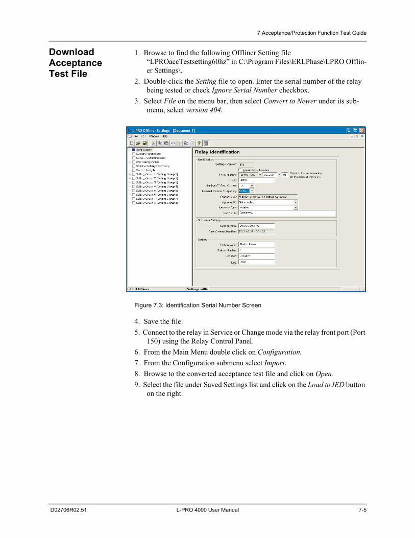
7 Acceptance/Protection Function Test Guide
D02706R02.51 L-PRO 4000 User Manual 7-5
Download Acceptance Test File
1. Browse to find the following Offliner Setting file “LPROaccTestsetting60hz” in C:\Program Files\ERLPhase\LPRO Offlin-er Settings\.
2. Double-click the Setting file to open. Enter the serial number of the relay being tested or check Ignore Serial Number checkbox.
3. Select File on the menu bar, then select Convert to Newer under its sub-menu, select version 404.
Figure 7.3: Identification Serial Number Screen
4. Save the file.5. Connect to the relay in Service or Change mode via the relay front port (Port
150) using the Relay Control Panel.6. From the Main Menu double click on Configuration.7. From the Configuration submenu select Import.8. Browse to the converted acceptance test file and click on Open.9. Select the file under Saved Settings list and click on the Load to IED button
on the right.
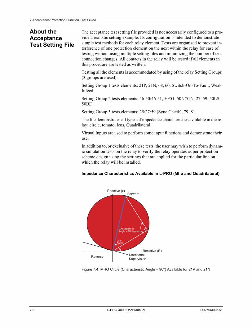
7 Acceptance/Protection Function Test Guide
7-6 L-PRO 4000 User Manual D02706R02.51
About the Acceptance Test Setting File
The acceptance test setting file provided is not necessarily configured to a pro-vide a realistic setting example. Its configuration is intended to demonstrate simple test methods for each relay element. Tests are organized to prevent in-terference of one protection element on the next within the relay for ease of testing without using multiple setting files and minimizing the number of test connection changes. All contacts in the relay will be tested if all elements in this procedure are tested as written.
Testing all the elements is accommodated by using of the relay Setting Groups (3 groups are used).
Setting Group 1 tests elements: 21P, 21N, 68, 60, Switch-On-To-Fault, Weak Infeed
Setting Group 2 tests elements: 46-50/46-51, 50/51, 50N/51N, 27, 59, 50LS, 50BF
Setting Group 3 tests elements: 25/27/59 (Sync Check), 79, 81
The file demonstrates all types of impedance characteristics available in the re-lay: circle, tomato, lens, Quadrilateral.
Virtual Inputs are used to perform some input functions and demonstrate their use.
In addition to, or exclusive of these tests, the user may wish to perform dynam-ic simulation tests on the relay to verify the relay operates as per protection scheme design using the settings that are applied for the particular line on which the relay will be installed.
Impedance Characteristics Available in L-PRO (Mho and Quadrilateral)
Figure 7.4: MHO Circle (Characteristic Angle = 90) Available for 21P and 21N
Reactive (x)
Resistive (R)
Reverse DirectionalSupervision
Forward
CharacteristicAngle = 90 degrees
LineAngle
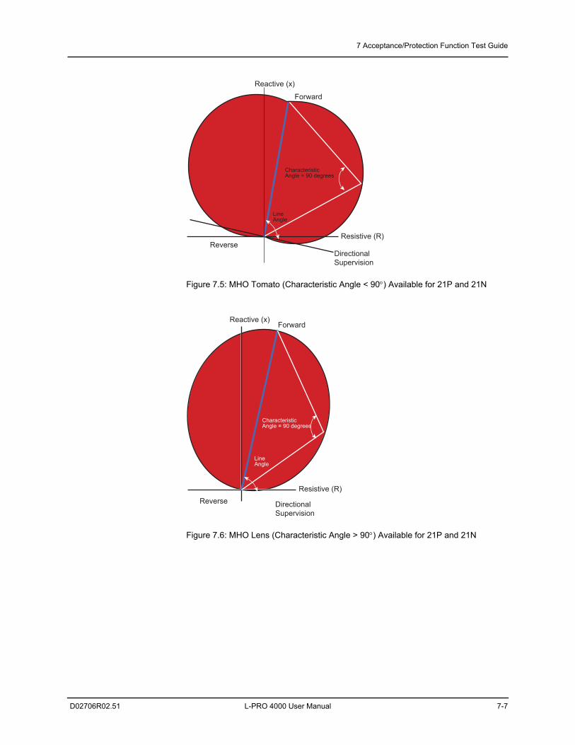
7 Acceptance/Protection Function Test Guide
D02706R02.51 L-PRO 4000 User Manual 7-7
Figure 7.5: MHO Tomato (Characteristic Angle < 90) Available for 21P and 21N
Figure 7.6: MHO Lens (Characteristic Angle > 90) Available for 21P and 21N
Reactive (x)
Resistive (R)Reverse
DirectionalSupervision
Forward
CharacteristicAngle = 90 degrees
LineAngle
Reactive (x)
Resistive (R)Reverse Directional
Supervision
Forward
CharacteristicAngle = 90 degrees
LineAngle
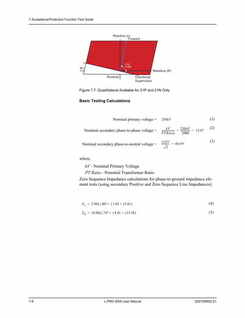
7 Acceptance/Protection Function Test Guide
7-8 L-PRO 4000 User Manual D02706R02.51
Figure 7.7: Quadrilateral Available for 21P and 21N Only
Basic Testing Calculations
where
kV - Nominal Primary VoltagePT Ratio - Potential Transformer Ratio
Zero Sequence Impedance calculations for phase-to-ground impedance ele-ment tests (using secondary Positive and Zero Sequence Line Impedances):
Nominal primary voltage = (1)
Nominal secondary phase-to-phase voltage = (2)
Nominal secondary phase-to-neutral voltage =(3)
(4)
(5)
Reactive (x)
Resistive (R)
Reverse DirectionalSupervision
Forward
LineAngle
R1
230kV
kVPTRatio---------------------- 230kV
2000---------------- 115V==
115V3
------------- 66.4V=
Z1 5.9 80 1.03 j5.81+ ==
Z0 16.0 74 4.41 j15.38+ ==
7 Acceptance/Protection Function Test Guide
D02706R02.51 L-PRO 4000 User Manual 7-9
The multiplier used to compensate phase-to-ground impedances:
21N Reach SettingsZone 1 Reach: Mho 4.72
Zone 2 Reach: Quadrilateral X: 7.38 , R: 6.00
Zone 3 Reach: Mho Forward 17.7 , Reverse 0.50
Zone 4 Reach: Mho Forward 0.00 , Reverse 4.72
Compensated 21N1 setting 4.72 (Zone 1 phase-to-ground compensated Mho impedance):
where
Z1 - Positive Sequence ImpedanceZ2 - Negative Sequence ImpedanceK0 - Factor
(6)
1 + K0 = (1 + 0.57-9.5) = (1 + 0.562 – j0.094) = (1.562 – j0.094) = 1.5693.5
(7)
(8)
K0Z0 Z1–3 Z1------------------=
3.38 j9.57+17.7 80
------------------------------ 10.15 70.5217.7 80
---------------------------------- 0.57 9.5– ===
4.41 1.03– j15.38 j5.81– + 3 5.9 80
------------------------------------------------------------------------------------=
4.72 80 1.569 3.5– 7.40 76.5=
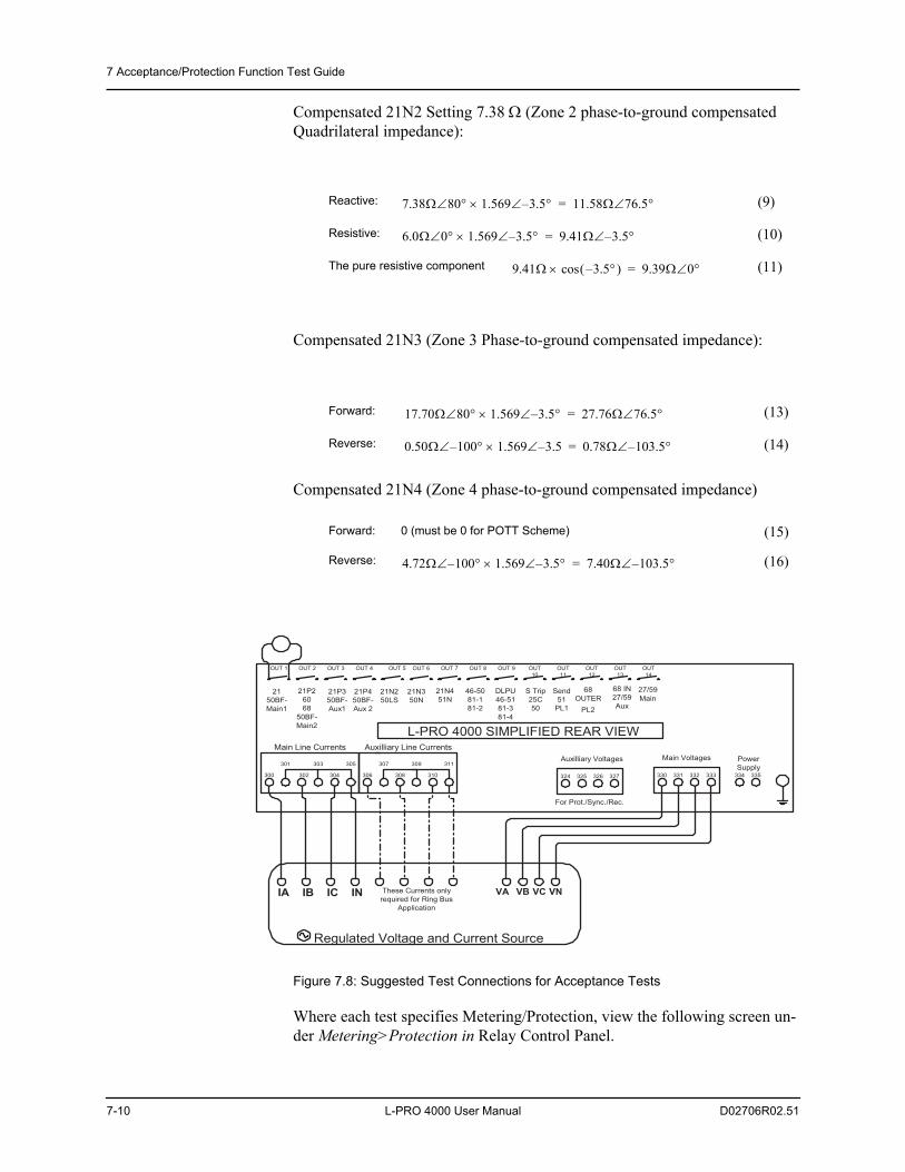
7 Acceptance/Protection Function Test Guide
7-10 L-PRO 4000 User Manual D02706R02.51
Compensated 21N2 Setting 7.38 (Zone 2 phase-to-ground compensated Quadrilateral impedance):
Compensated 21N3 (Zone 3 Phase-to-ground compensated impedance):
Compensated 21N4 (Zone 4 phase-to-ground compensated impedance)
Figure 7.8: Suggested Test Connections for Acceptance Tests
Where each test specifies Metering/Protection, view the following screen un-der Metering>Protection in Relay Control Panel.
Reactive: (9)
Resistive: (10)
The pure resistive component (11)
Forward: (13)
Reverse: (14)
Forward: 0 (must be 0 for POTT Scheme) (15)
Reverse: (16)
7.38 80 1.569 3.5– 11.58 76.5=
6.0 0 1.569 3.5– 9.41 3.5–=
9.41 3.5– cos 9.39 0=
17.70 80 1.569 3.5– 27.76 76.5=
0.50 100– 1.569 3.5– 0.78 103.5–=
4.72 100– 1.569 3.5– 7.40 103.5–=
L-PRO 4000 SIMPLIFIED REAR VIEW
OUT 1 OUT 2 OUT 3 OUT 4 OUT 5 OUT 6 OUT 7 OUT 8 OUT 9 OUT10
OUT11
OUT12
OUT13
OUT14
2150BF-Main1
21P26068
50BF-Main2
21P350BF-Aux1
21P450BF-Aux 2
21N250LS
21N350N
21N451N
46-5081-181-2
DLPU46-5181-381-4
68OUTER
PL2
300
301
302
303
304
305
306
307
308
309
310
311PowerSupply
334 335
Main Line Currents Auxilliary Line CurrentsMain Voltages
Regulated Voltage and Current Source
IA IB IC IN These Currents onlyrequired for Ring Bus
Application
VA VB VC VN
330 331 332 333324 325 326 327
Auxilliary Voltages
For Prot./Sync./Rec.
68 IN27/59Aux
S Trip25C50
Send51
PL1
27/59Main
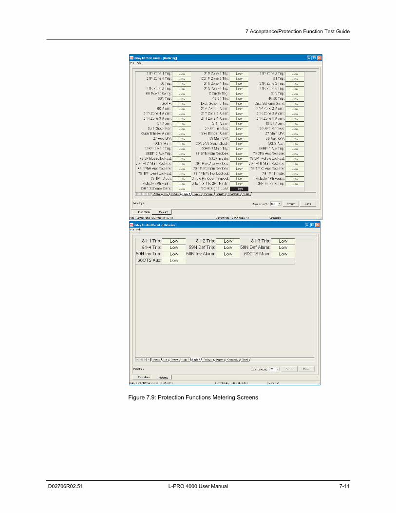
7 Acceptance/Protection Function Test Guide
D02706R02.51 L-PRO 4000 User Manual 7-11
Figure 7.9: Protection Functions Metering Screens
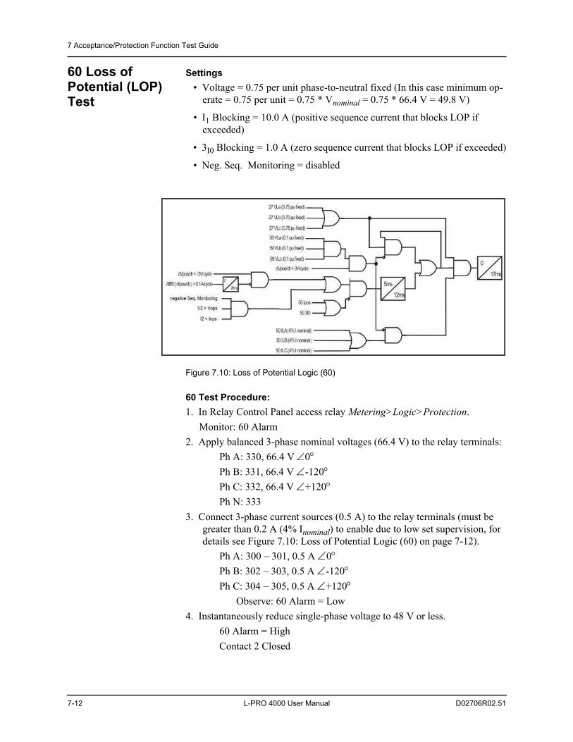
7 Acceptance/Protection Function Test Guide
7-12 L-PRO 4000 User Manual D02706R02.51
60 Loss of Potential (LOP) Test
Settings • Voltage = 0.75 per unit phase-to-neutral fixed (In this case minimum op-
erate = 0.75 per unit = 0.75 * Vnominal = 0.75 * 66.4 V = 49.8 V)
• I1 Blocking = 10.0 A (positive sequence current that blocks LOP if exceeded)
• 3I0 Blocking = 1.0 A (zero sequence current that blocks LOP if exceeded)
• Neg. Seq. Monitoring = disabled
Figure 7.10: Loss of Potential Logic (60)
60 Test Procedure:1. In Relay Control Panel access relay Metering>Logic>Protection.
Monitor: 60 Alarm2. Apply balanced 3-phase nominal voltages (66.4 V) to the relay terminals:
Ph A: 330, 66.4 V 0Ph B: 331, 66.4 V -120Ph C: 332, 66.4 V +120Ph N: 333
3. Connect 3-phase current sources (0.5 A) to the relay terminals (must be greater than 0.2 A (4% Inominal) to enable due to low set supervision, for details see Figure 7.10: Loss of Potential Logic (60) on page 7-12).
Ph A: 300 – 301, 0.5 A 0Ph B: 302 – 303, 0.5 A -120Ph C: 304 – 305, 0.5 A +120
Observe: 60 Alarm = Low4. Instantaneously reduce single-phase voltage to 48 V or less.
60 Alarm = HighContact 2 Closed
7 Acceptance/Protection Function Test Guide
D02706R02.51 L-PRO 4000 User Manual 7-13
Testing the LOP I1 Supervision:1. Restore 3-phase voltages to 66.4 V.
Observe 60 Alarm = LowContact 2 = Open
2. Increase balanced 3-phase currents to 10.1 A per phase.3. Reduce single-phase voltage to 0.
Observe 60 Alarm remains lowObserve Contact 2 remains open
4. Reduce currents to 0.
Testing the LOP 3IO Supervision1. Restore 3-phase voltages to 66.4 V.
Observe 60 Alarm = LowContact 2 = Open
2. Increase any single-phase current to 1.1 A.3. Reduce single-phase voltage to 0.
Observe 60 Alarm remains low.Observe Contact 2 remains open.
4. Reduce all sources to 0.
Testing Negative Seq. Supervision1. Instantaneously, apply following signals
Voltages:Ph A: 330, 66.4 V < 0Ph B: 331, 0 VPh C: 332, 0 VPh N:333
Currents:Ph A: 300 – 301, 0.5A < 0Ph A: 302 – 303, 0.5A < -120Ph A: 304 – 305, 0.5A < +120
Observe 60 Alarm = Low2. Reduce all sources to 0.3. Change settings as given below.
Enable Neg. Seq. Monitoring Vnps = 10.0 VInps = 0.5 A
4. Repeat, step 1. Observe 60 Alarm = High
5. Reduce all sources to 0.End of 60 test.
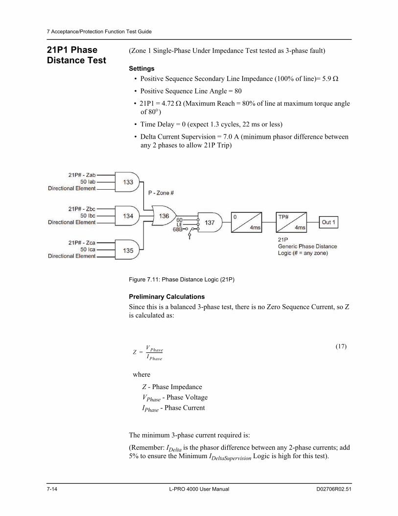
7 Acceptance/Protection Function Test Guide
7-14 L-PRO 4000 User Manual D02706R02.51
21P1 Phase Distance Test
(Zone 1 Single-Phase Under Impedance Test tested as 3-phase fault)
Settings • Positive Sequence Secondary Line Impedance (100% of line)= 5.9
• Positive Sequence Line Angle = 80
• 21P1 = 4.72 (Maximum Reach = 80% of line at maximum torque angle of 80)
• Time Delay = 0 (expect 1.3 cycles, 22 ms or less)
• Delta Current Supervision = 7.0 A (minimum phasor difference between any 2 phases to allow 21P Trip)
Figure 7.11: Phase Distance Logic (21P)
Preliminary CalculationsSince this is a balanced 3-phase test, there is no Zero Sequence Current, so Z is calculated as:
The minimum 3-phase current required is:
(Remember: IDelta is the phasor difference between any 2-phase currents; add 5% to ensure the Minimum IDeltaSupervision Logic is high for this test).
where
Z - Phase ImpedanceVPhase - Phase VoltageIPhase - Phase Current
(17)Z
V PhaseI Phase-----------------=
7 Acceptance/Protection Function Test Guide
D02706R02.51 L-PRO 4000 User Manual 7-15
21P1 Test Procedure1. In Relay Control Panel access relay Metering>Logic>Protection.
Monitor 21P1 Zone 1Trip2. Apply balanced 3-phase nominal voltages (66.4 V) to the relay terminals.
Ph A: 330, 66.4 V 0Ph B: 331, 66.4 V -120Ph C: 332, 66.4 V +120Ph N: 333
3. Connect 3-phase current sources (4.24 A lagging voltages by 80) to the relay terminals:
Ph A: 300 – 301, 4.24 A 0Ph B: 302 – 303, 4.24 A Ph C: 304 – 305, 4.24 A
Observe 21P1 Trip = Low4. Simultaneously reduce 3-phase voltages.
At 21.0 to 19.0 V (expect 20.0 V) 21 Trip = High (Note that Contact 1 will probably close earlier than 21-1 Trip going high, because Z2 and Z3 trip elements are mapped to the same output contact, and the length of time this fault will be ap-plied.)
Testing the Zone 1 Phase Time Delay1. Monitor (Timer Stop) on normally open Output Contact 1 (202 – 203).2. Set timer to start from 3-phase amp current transition (i.e. current off to on).3. Apply (keep on) balanced 3-phase voltages (20.0 V) to the relay terminals.
Ph A: 330, 20.0 V Ph B: 331, 20.0 V -120Ph C: 332, 20.0 V +120Ph N: 333
4. Apply 3-phase currents from 0 to 5.3 A to start the timer (this is 80% of Zone 1 Reach = 64% of the line = 12.4 miles).
where
Imin- Minimum Current settingIDeltaSupervision - Phase difference between any 2-phase currents
(18)I min
I DeltaSupervision 105 percent
3----------------------------------------------------------------------------- 7.0 1.05
3------------------------ 4.24amps===
7 Acceptance/Protection Function Test Guide
7-16 L-PRO 4000 User Manual D02706R02.51
Ph A: 300 –301, 5.3 A –-80Ph B: 302 –303, 5.3 A – -200Ph C: 303 –304, 5.3 A – +40Expect operating time less than 1.3 cycles with CCVT algorithm dis-abled.
End of 21P1 test.
21P2 Phase Distance Test
Zone 2 Phase Under Impedance tested as 2-phase fault
Settings • Positive Sequence Secondary Line Impedance (100% of line) = 5.9 Pos-
itive Sequence Line Angle (Z1) = 80
• 21P2= 7.38 (Maximum Reach = 125% of line, 24.25 miles at maximum torque angle of 80)
• Time Delay = 400 ms (expect 1.0 to 1.3 cycle additional delay due to in-herent detection and contact times)
• Delta Current Supervision = 3.0 A (minimum phasor difference between any 2 phases to allow 21P2 Trip)
This test example shows how to test for a phase-to-phase fault.
Determine the voltage and current quantities required to perform this test.
1. Determine the minimum current required (as per Idelta supervision setting).2. Determine an appropriate fault voltage to use for the test.3. Determine the 3-phase voltage phasors required to create the fault voltage.
1. Minimum current required for this test:I delta Supervision Setting (the phasor difference of 2 phases) = 3.0 A. Cur-rent is injected into polarity of B-phase and out of polarity of C-phase. Therefore B-phase and C-phase currents are equal in magnitude but 180 out of phase.
The minimum delta current required = 3.0 A; add 5% to ensure supervision is met:
Since B-phase = C-phase, actual minimum current required is equal to
(19)
(20)
3.0 105 percent 3.2A=
3.22
------- 1.6A=
7 Acceptance/Protection Function Test Guide
D02706R02.51 L-PRO 4000 User Manual 7-17
2. Use the minimum test current to determine what voltage would be appro-priate for this test.
From Equation (21) we can derive the formula:
And using appropriate values, the Minimum Fault Voltage is
(21)
(22)
where
VFaultMin - Minimum Fault VoltageITestMin - Minimum Fault Test Current
(23)
ZV FaultMin
2 I TestMin-----------------------------=
V FaultMin Z 2 I TestMin=
V FaultMin 7.38 2 1.6A 23.6V==
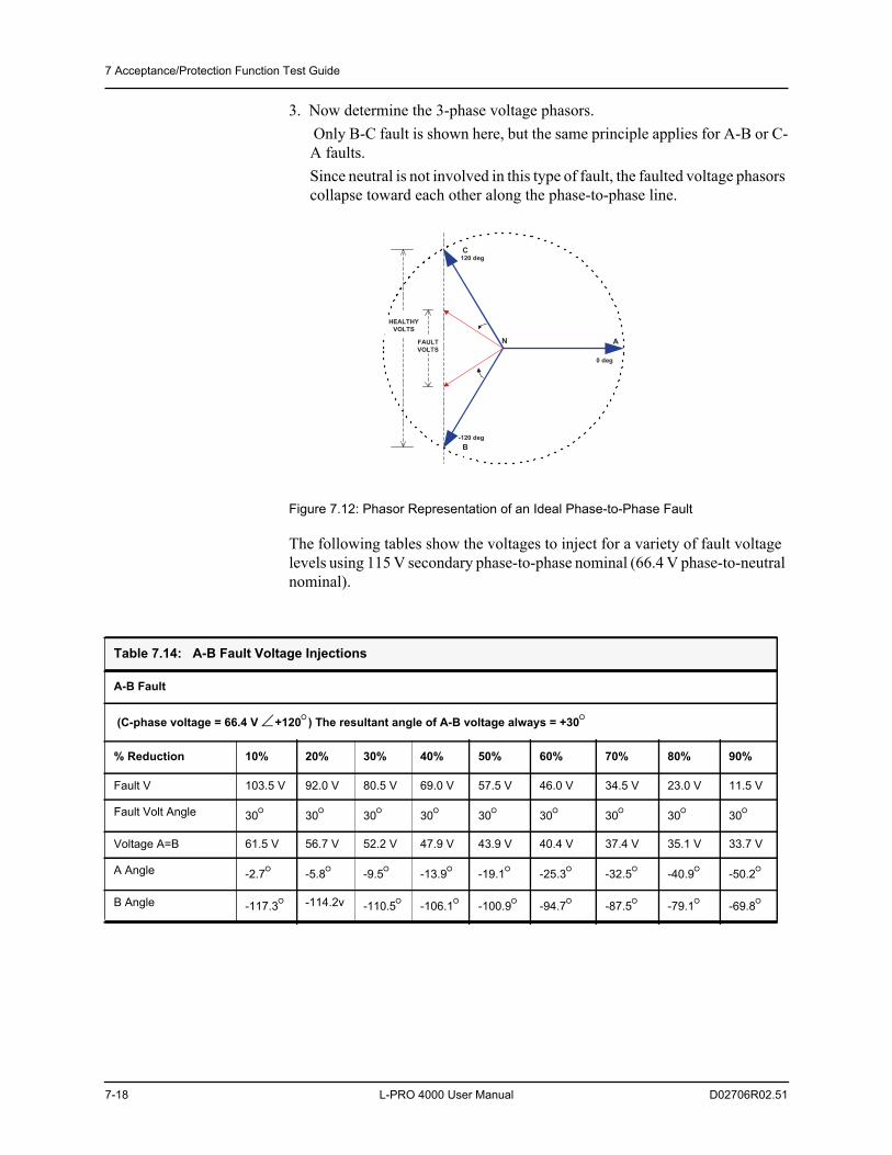
7 Acceptance/Protection Function Test Guide
7-18 L-PRO 4000 User Manual D02706R02.51
3. Now determine the 3-phase voltage phasors. Only B-C fault is shown here, but the same principle applies for A-B or C-A faults.Since neutral is not involved in this type of fault, the faulted voltage phasors collapse toward each other along the phase-to-phase line.
Figure 7.12: Phasor Representation of an Ideal Phase-to-Phase Fault
The following tables show the voltages to inject for a variety of fault voltage levels using 115 V secondary phase-to-phase nominal (66.4 V phase-to-neutral nominal).
0 deg
FAULTVOLTS
HEALTHYVOLTS
-120 deg
120 deg
A
B
C
N
Table 7.14: A-B Fault Voltage Injections
A-B Fault
(C-phase voltage = 66.4 V +120) The resultant angle of A-B voltage always = +30
% Reduction 10% 20% 30% 40% 50% 60% 70% 80% 90%
Fault V 103.5 V 92.0 V 80.5 V 69.0 V 57.5 V 46.0 V 34.5 V 23.0 V 11.5 V
Fault Volt Angle 30 30 30 30 30 30 30 30 30
Voltage A=B 61.5 V 56.7 V 52.2 V 47.9 V 43.9 V 40.4 V 37.4 V 35.1 V 33.7 V
A Angle -2.7 -5.8 -9.5 -13.9 -19.1 -25.3 -32.5 -40.9 -50.2
B Angle -117.3 -114.2v -110.5 -106.1 -100.9 -94.7 -87.5 -79.1 -69.8
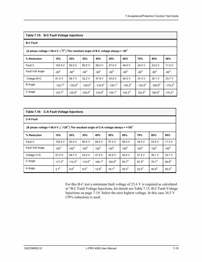
7 Acceptance/Protection Function Test Guide
D02706R02.51 L-PRO 4000 User Manual 7-19
For this B-C test a minimum fault voltage of 23.6 V is required as calculated in “B-C Fault Voltage Injections, for details see Table 7.15: B-C Fault Voltage Injections on page 7-19. Select the next highest voltage. In this case 34.5 V (70% reduction) is used.
Table 7.15: B-C Fault Voltage Injections
B-C Fault
(A phase voltage = 66.4 V) The resultant angle of B-C voltage always = -90
% Reduction 10% 20% 30% 40% 50% 60% 70% 80% 90%
Fault V 103.5 V 92.0 V 80.5 V 69.0 V 57.5 V 46.0 V 34.5 V 23.0 V 11.5 V
Fault Volt Angle -90 -90 -90 -90 -90 -90 -90 -90 -90
Voltage B=C 61.5 V 56.7 V 52.2 V 47.9 V 43.9 V 40.4 V 37.4 V 35.1 V 33.7 V
B Angle -122.7 -125.8 -129.5 -133.9 -139.1 -145.3 -152.5 -160.9 -170.2
C Angle 122.7 125.8 129.5 133.9 139.1 145.3 152.5 160.9 170.2
Table 7.16: C-A Fault Voltage Injections
C-A Fault
(B phase voltage = 66.4 V -120) The resultant angle of C-A voltage always = +150
% Reduction 10% 20% 30% 40% 50% 60% 70% 80% 90%
Fault V 103.5 V 92.0 V 80.5 V 69.0 V 57.5 V 46.0 V 34.5 V 23.0 V 11.5 V
Fault Volt Angle 150 150 150 150 150 150 150 150 150
Voltage C=A 61.5 V 56.7 V 52.2 V 47.9 V 43.9 V 40.4 V 37.4 V 35.1 V 33.7 V
C Angle 117.3 114.2 110.5 106.1 100.9 94.7 87.5 79.1 69.8
A Angle 2.7 5.8 9.5 13.9 19.1 25.3 32.5 40.9 50.2
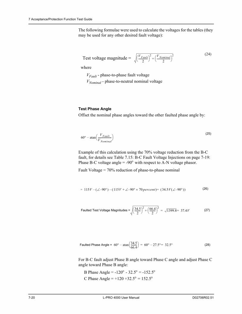
7 Acceptance/Protection Function Test Guide
7-20 L-PRO 4000 User Manual D02706R02.51
The following formulae were used to calculate the voltages for the tables (they may be used for any other desired fault voltage):
Test Phase AngleOffset the nominal phase angles toward the other faulted phase angle by:
Example of this calculation using the 70% voltage reduction from the B-C fault, for details see Table 7.15: B-C Fault Voltage Injections on page 7-19: Phase B-C voltage angle = -90 with respect to A-N voltage phasor.
Fault Voltage = 70% reduction of phase-to-phase nominal
For B-C fault adjust Phase B angle toward Phase C angle and adjust Phase C angle toward Phase B angle:
B Phase Angle = -120 - 32.5 = -152.5C Phase Angle = +120 +32.5 = 152.5
where
VFault - phase-to-phase fault voltageVNominal - phase-to-neutral nominal voltage
(24)
(25)
(26)
(27)
(28)
V Fault2
----------------
2 V Nominal2
-----------------------
2+Test voltage magnitude =
60V Fault
V Nominal----------------------- atan–
115V= 90– – 115V 90 70 percent–+ 34.5V 90– =–
34.52
---------- 2 66.4
2---------- 2
+ 1399.8 37.4V==Faulted Test Voltage Magnitudes =
Faulted Phase Angle = 60 34.566.4---------- atan– 60 27.5 32.5=–=
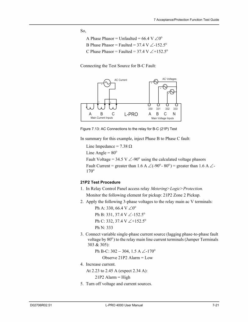
7 Acceptance/Protection Function Test Guide
D02706R02.51 L-PRO 4000 User Manual 7-21
So,
A Phase Phasor = Unfaulted = 66.4 V 0B Phase Phasor = Faulted = 37.4 V -152.5C Phase Phasor = Faulted = 37.4 V +152.5
Connecting the Test Source for B-C Fault:
Figure 7.13: AC Connections to the relay for B-C (21P) Test
In summary for this example, inject Phase B to Phase C fault:
Line Impedance = 7.38 Line Angle = 80Fault Voltage = 34.5 V -90 using the calculated voltage phasorsFault Current = greater than 1.6 A (-90- 80) = greater than 1.6 A -170
21P2 Test Procedure1. In Relay Control Panel access relay Metering>Logic>Protection.
Monitor the following element for pickup: 21P2 Zone 2 Pickup.2. Apply the following 3-phase voltages to the relay main ac V terminals:
Ph A: 330, 66.4 V 0Ph B: 331, 37.4 V -152.5Ph C: 332, 37.4 V +152.5Ph N: 333
3. Connect variable single-phase current source (lagging phase-to-phase fault voltage by 80) to the relay main line current terminals (Jumper Terminals 303 & 305):
Ph B-C: 302 –304, 1.5 A -170Observe 21P2 Alarm = Low
4. Increase current.At 2.23 to 2.45 A (expect 2.34 A):
21P2 Alarm = High 5. Turn off voltage and current sources.
330
A B C A B C NMain Current Inputs Main Voltage Inputs
L-PRO331 333332
AC Current AC Voltages
++
+
+
+
+
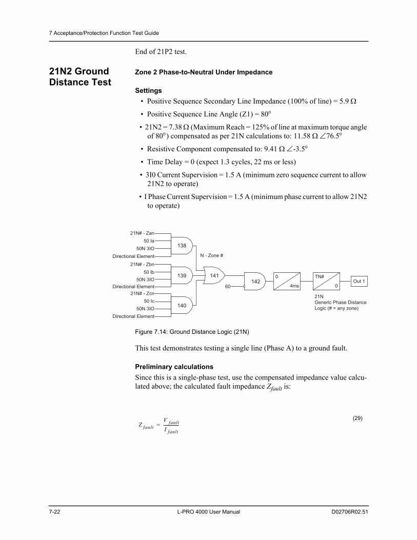
7 Acceptance/Protection Function Test Guide
7-22 L-PRO 4000 User Manual D02706R02.51
End of 21P2 test.
21N2 Ground Distance Test
Zone 2 Phase-to-Neutral Under Impedance
Settings • Positive Sequence Secondary Line Impedance (100% of line) = 5.9
• Positive Sequence Line Angle (Z1) = 80
• 21N2 = 7.38 (Maximum Reach = 125% of line at maximum torque angle of 80) compensated as per 21N calculations to: 11.58 76.5
• Resistive Component compensated to: 9.41 -3.5
• Time Delay = 0 (expect 1.3 cycles, 22 ms or less)
• 3I0 Current Supervision = 1.5 A (minimum zero sequence current to allow 21N2 to operate)
• I Phase Current Supervision = 1.5 A (minimum phase current to allow 21N2 to operate)
Figure 7.14: Ground Distance Logic (21N)
This test demonstrates testing a single line (Phase A) to a ground fault.
Preliminary calculationsSince this is a single-phase test, use the compensated impedance value calcu-lated above; the calculated fault impedance Zfault is:
0
4ms
21N# - Zan
50 Ia
Directional Element
21N# - Zbn
50 Ib
Directional Element
21N# - Zcn
50 Ic
Directional Element
N - Zone #
60
TN#
0Out 1
21N
Generic Phase Distance
Logic (# = any zone)50N 3IO
50N 3IO
50N 3IO
142141
138
139
140
(29)Z fault
V faultI fault---------------=
7 Acceptance/Protection Function Test Guide
D02706R02.51 L-PRO 4000 User Manual 7-23
The minimum single-phase current required is:
(Remember: Testing single-phase, so need to exceed the greater of Iphase and 3Io supervision settings; add 5% to ensure the minimum supervision logic is high for this test):
This element has been set for Quadrilateral characteristic.
21N2 Reactive Test Procedure1. In Relay Control Panel access relay Metering>Logic>Protection.
Monitor: 21N2 Zone 2 Pickup2. Apply balanced 3-phase nominal voltages (66.4 V) to the relay terminals.
Ph A: 330, 66.4 V 0Ph B: 331, 66.4 V -120Ph C: 332, 66.4 V +120Ph N: 333
3. Connect single-phase current source to the relay terminals.Ph A: 300 –301, 1.58 A -76.5
Observe 21N2 Pickup = Low4. Reduce Phase A voltage.
At 17.4 to 19.2 V (expect 18.3 V):21N2 Pickup = High (After 400 ms: 21N2 Trip = High)
21N2 Resistive Test Procedure1. In Relay Control Panel access relay Metering>Logic>Protection.
Monitor: 21N2 Zone 2 Pickup 2. Apply balanced 3-phase nominal voltages (66.4 V) to the relay terminals.
Ph A: 330, 66.4 V 0Ph B: 331, 66.4 V -120Ph C: 332, 66.4 V +120Ph N: 333
3. Connect single -phase current source to the relay terminals.Ph A: 300 –301, 1.58 A +3.5
Observe 21N2 Pickup = Low4. Reduce Phase A voltage.
At 15.6 to 14.2 V (expect 14.9 V).21N2 Pickup = High After 400 ms: 21N2 Trip = High
(30)IMin = (Greater of Iphase and 3Io Supervision)x105% = 1.5x1.05 = 1.58A
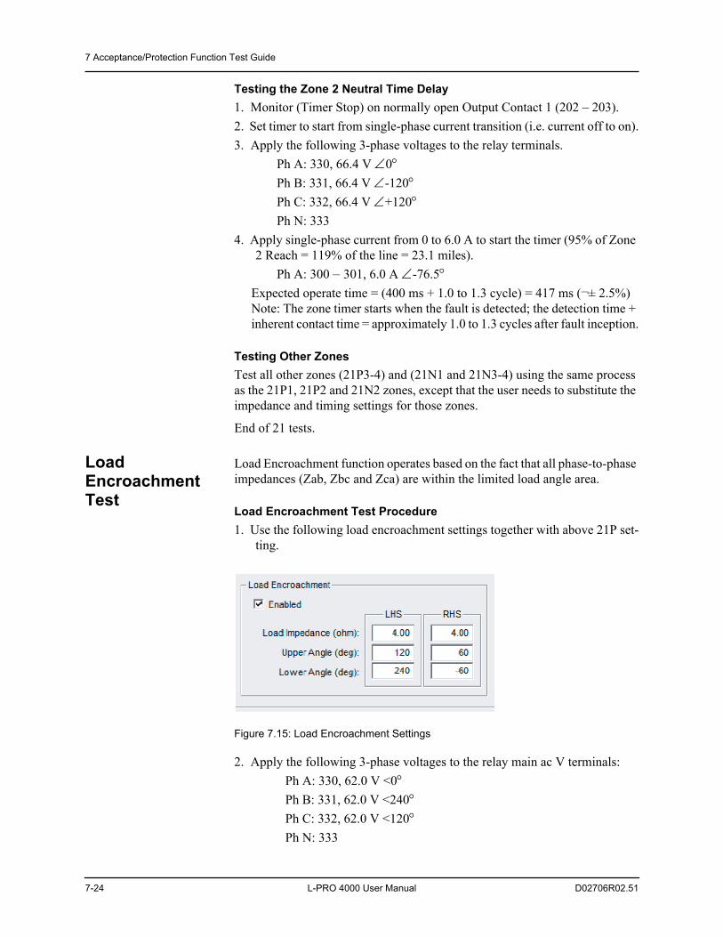
7 Acceptance/Protection Function Test Guide
7-24 L-PRO 4000 User Manual D02706R02.51
Testing the Zone 2 Neutral Time Delay1. Monitor (Timer Stop) on normally open Output Contact 1 (202 – 203).2. Set timer to start from single-phase current transition (i.e. current off to on).3. Apply the following 3-phase voltages to the relay terminals.
Ph A: 330, 66.4 V 0Ph B: 331, 66.4 V -120Ph C: 332, 66.4 V +120Ph N: 333
4. Apply single-phase current from 0 to 6.0 A to start the timer (95% of Zone 2 Reach = 119% of the line = 23.1 miles).
Ph A: 300 –301, 6.0 A -76.5Expected operate time = (400 ms + 1.0 to 1.3 cycle) = 417 ms (¬± 2.5%) Note: The zone timer starts when the fault is detected; the detection time + inherent contact time = approximately 1.0 to 1.3 cycles after fault inception.
Testing Other ZonesTest all other zones (21P3-4) and (21N1 and 21N3-4) using the same process as the 21P1, 21P2 and 21N2 zones, except that the user needs to substitute the impedance and timing settings for those zones.
End of 21 tests.
Load Encroachment Test
Load Encroachment function operates based on the fact that all phase-to-phase impedances (Zab, Zbc and Zca) are within the limited load angle area.
Load Encroachment Test Procedure1. Use the following load encroachment settings together with above 21P set-
ting.
Figure 7.15: Load Encroachment Settings
2. Apply the following 3-phase voltages to the relay main ac V terminals:Ph A: 330, 62.0 V <0Ph B: 331, 62.0 V <240Ph C: 332, 62.0 V <120Ph N: 333
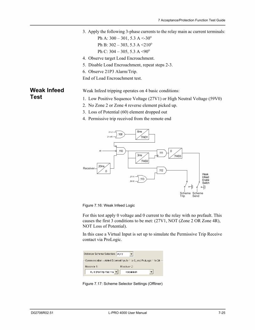
7 Acceptance/Protection Function Test Guide
D02706R02.51 L-PRO 4000 User Manual 7-25
3. Apply the following 3-phase currents to the relay main ac current terminals:Ph A: 300 – 301, 5.3 A <-30Ph B: 302 – 303, 5.3 A <210Ph C: 304 – 305, 5.3 A <90
4. Observe target Load Encroachment.5. Disable Load Encroachment, repeat steps 2-3. 6. Observe 21P3 Alarm/Trip.End of Load Encroachment test.
Weak Infeed Test
Weak Infeed tripping operates on 4 basic conditions:
1. Low Positive Sequence Voltage (27V1) or High Neutral Voltage (59V0)2. No Zone 2 or Zone 4 reverse element picked up.3. Loss of Potential (60) element dropped out4. Permissive trip received from the remote end
Figure 7.16: Weak Infeed Logic
For this test apply 0 voltage and 0 current to the relay with no prefault. This causes the first 3 conditions to be met: (27V1, NOT (Zone 2 OR Zone 4R), NOT Loss of Potential).
In this case a Virtual Input is set up to simulate the Permissive Trip Receive contact via ProLogic.
Figure 7.17: Scheme Selector Settings (Offliner)
113
1110
TWD33ms
TWD2
108
110
6ms
TWD1
112
20ms
0
60
27 V1
59 V0
Weak Infeed EnableSwitch
21-2
21-4R
Receiver
SchemeTrip
SchemeSend
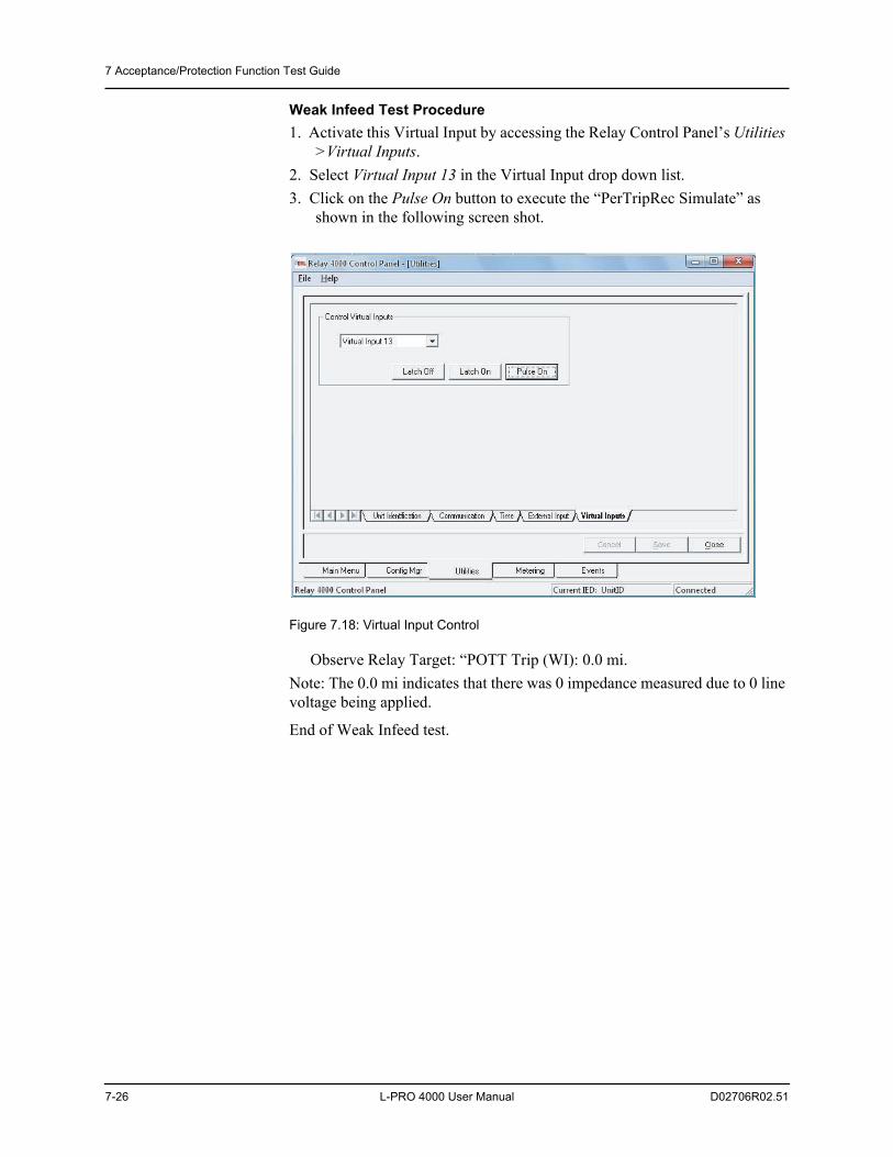
7 Acceptance/Protection Function Test Guide
7-26 L-PRO 4000 User Manual D02706R02.51
Weak Infeed Test Procedure1. Activate this Virtual Input by accessing the Relay Control Panel’s Utilities
>Virtual Inputs.2. Select Virtual Input 13 in the Virtual Input drop down list.3. Click on the Pulse On button to execute the “PerTripRec Simulate” as
shown in the following screen shot.
Figure 7.18: Virtual Input Control
Observe Relay Target: “POTT Trip (WI): 0.0 mi.Note: The 0.0 mi indicates that there was 0 impedance measured due to 0 line voltage being applied.
End of Weak Infeed test.
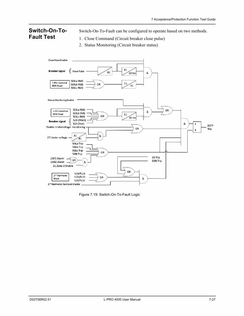
7 Acceptance/Protection Function Test Guide
D02706R02.51 L-PRO 4000 User Manual 7-27
Switch-On-To-Fault Test
Switch-On-To-Fault can be configured to operate based on two methods.
1. Close Command (Circuit breaker close pulse)2. Status Monitoring (Circuit breaker status)
Figure 7.19: Switch-On-To-Fault Logic
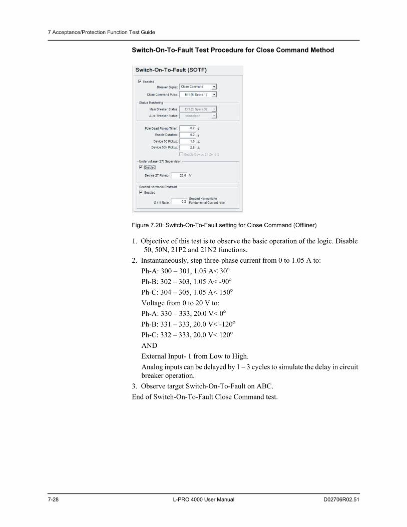
7 Acceptance/Protection Function Test Guide
7-28 L-PRO 4000 User Manual D02706R02.51
Switch-On-To-Fault Test Procedure for Close Command Method
Figure 7.20: Switch-On-To-Fault setting for Close Command (Offliner)
1. Objective of this test is to observe the basic operation of the logic. Disable 50, 50N, 21P2 and 21N2 functions.
2. Instantaneously, step three-phase current from 0 to 1.05 A to:Ph-A: 300 – 301, 1.05 A< 30Ph-B: 302 – 303, 1.05 A< -90Ph-C: 304 – 305, 1.05 A< 150Voltage from 0 to 20 V to:Ph-A: 330 – 333, 20.0 V< 0Ph-B: 331 – 333, 20.0 V< -120Ph-C: 332 – 333, 20.0 V< 120ANDExternal Input- 1 from Low to High.Analog inputs can be delayed by 1 – 3 cycles to simulate the delay in circuit breaker operation.
3. Observe target Switch-On-To-Fault on ABC.End of Switch-On-To-Fault Close Command test.
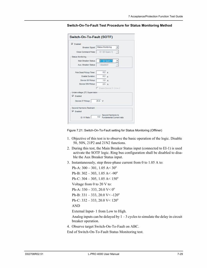
7 Acceptance/Protection Function Test Guide
D02706R02.51 L-PRO 4000 User Manual 7-29
Switch-On-To-Fault Test Procedure for Status Monitoring Method
Figure 7.21: Switch-On-To-Fault setting for Status Monitoring (Offliner)
1. Objective of this test is to observe the basic operation of the logic. Disable 50, 50N, 21P2 and 21N2 functions.
2. During this test, the Main Breaker Status input (connected to EI-1) is used activate the SOTF logic. Ring bus configuration shall be disabled to disa-ble the Aux Breaker Status input.
3. Instantaneously, step three-phase current from 0 to 1.05 A to:Ph-A: 300 – 301, 1.05 A< 30Ph-B: 302 – 303, 1.05 A< -90Ph-C: 304 – 305, 1.05 A< 150Voltage from 0 to 20 V to:Ph-A: 330 – 333, 20.0 V< 0Ph-B: 331 – 333, 20.0 V< -120Ph-C: 332 – 333, 20.0 V< 120ANDExternal Input- 1 from Low to High.Analog inputs can be delayed by 1 – 3 cycles to simulate the delay in circuit breaker operation.
4. Observe target Switch-On-To-Fault on ABC.End of Switch-On-To-Fault Status Monitoring test.
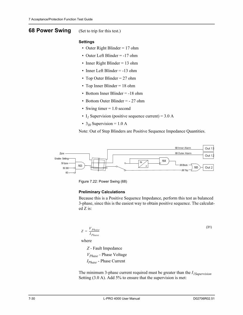
7 Acceptance/Protection Function Test Guide
7-30 L-PRO 4000 User Manual D02706R02.51
68 Power Swing (Set to trip for this test.)
Settings • Outer Right Blinder = 17 ohm
• Outer Left Blinder = -17 ohm
• Inner Right Blinder = 13 ohm
• Inner Left Blinder = -13 ohm
• Top Outer Blinder = 27 ohm
• Top Inner Blinder = 18 ohm
• Bottom Inner Blinder = -18 ohm
• Bottom Outer Blinder = - 27 ohm
• Swing timer = 1.0 second
• I1 Supervision (positive sequence current) = 3.0 A
• 3I0 Supervision = 1.0 A
Note: Out of Step Blinders are Positive Sequence Impedance Quantities.
Figure 7.22: Power Swing (68)
Preliminary CalculationsBecause this is a Positive Sequence Impedance, perform this test as balanced 3-phase, since this is the easiest way to obtain positive sequence. The calculat-ed Z is:
The minimum 3-phase current required must be greater than the I1Supervision Setting (3.0 A). Add 5% to ensure that the supervision is met:
Enable Setting
50 Ipos
60
50 3I0 163
Zpos
164TB
0
68 Trip
68 Block 165 Out 2
Out 13
Out 12
68 Inner Alarm
68 Outer Alarm
X
R
where
Z - Fault ImpedanceVPhase - Phase VoltageIPhase - Phase Current
(31)Z
V PhaseI Phase-----------------=
7 Acceptance/Protection Function Test Guide
D02706R02.51 L-PRO 4000 User Manual 7-31
68 Outer Right Test Procedure1. In Relay Control Panel access relay Metering>Logic>Protection.
Monitor: 68 OutBlinder AlarmContact 12 with an ohmmeter
2. Apply balanced 3-phase nominal voltages (66.4 V) to the relay terminals.Ph A: 330, 66.4 V 0Ph B: 331, 66.4 V -120Ph C: 332, 66.4 V +120Ph N: 333
3. Connect 3-phase current sources (3.15 A in phase with voltages) to the relay terminals: Ph A: 300 –301, 3.15 A 0
Ph B: 302 – 303, 3.15 A -120Ph C: 303 –304, 3.15 A +120
Observe 68 OutBlinder Alarm = LowContact 12 = Open
4. Simultaneously increase (ramp up) 3-phase currents.At 3.72 to 4.10 A (expect 3.91A):
68 OutBlinder Alarm = HighContact 12 = Closed
End of 68 Outer test.
68 Inner Left Test Procedure1. In Relay Control Panel access relay Metering>Logic>Protection.
Monitor:68 InnBlinder Alarm.Output Contact 13 with an ohmmeter.
2. Apply balanced 3-phase nominal voltages (66.4 V) to the relay terminals:Ph A: 330, 66.4 V 0Ph B: 331, 66.4 V -120Ph C: 332, 66.4 V +120Ph N: 333
where
IMin - Minimum Current I1Supervision - Positive Sequence Supervision current setting
(32)IMin = I1Supervision x 105% = 3.0 x 1.05 = 3.15A
7 Acceptance/Protection Function Test Guide
7-32 L-PRO 4000 User Manual D02706R02.51
3. Connect 3-phase current sources (3.15 A 180 from voltages) to the relay terminals.
Ph A: 300 –301, 3.15 A 180Ph B: 302 –303, 3.15 A +60Ph C: 304 –305, 3.15 A -60Observe 68 InnBlinder Alarm = LowContact 13 = Open
4. Simultaneously increase (ramp up) 3-phase currents.At 4.86 to 5.36 A (expect 5.11 A):
68 InnBlinder Alarm = HighContact 13 = Closed
Testing the 68 Swing Timer Delay1. Monitor (Timer Stop) on normally open Output Contact 2 (204 –205).2. Test at impedance between Inner and Outer Right Blinders = 15 03. Set timer to start from 3-phase current transition (i.e. current off to on).4. Apply (keep on) balanced 3-phase voltages (66.4 V) to the relay terminals.
Ph A: 330, 66.4 V 0Ph B: 331, 66.4 V -120Ph C: 332, 66.4 V +120Ph N: 333
5. Apply 3-phase currents from 0 to 4.43 A to start the timer.Ph A: 300 – 301, 4.43 A 0Ph B: 302 – 303, 4.43 A -120Ph C: 304 – 305, 4.43 A 120
Expect operating time 1.0 second + inherent 1.0 to 1.3 cycle detection time.Observe target: “Out Of Step: Trip”.
End of 68 Swing Timer test.
Change Setting Group
For the next group of tests using the Acceptance Test file change to Setting Group 2.
1. In Relay Control Panel access Utilities>Virtual Inputs.2. Select corresponding virtual input for “Switch to SG2”.3. Click on Pulse On button to execute the command.4. The Active Setting Group will become Group 2.
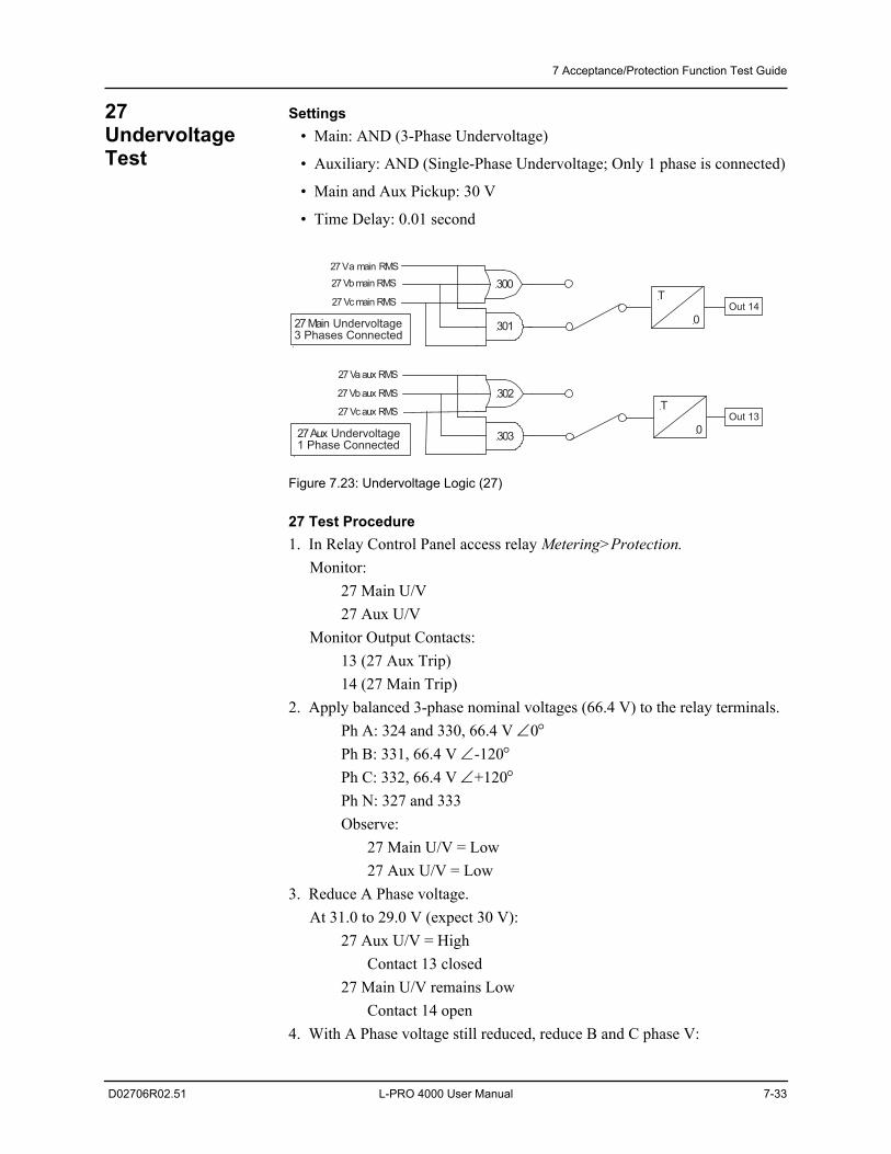
7 Acceptance/Protection Function Test Guide
D02706R02.51 L-PRO 4000 User Manual 7-33
27 Undervoltage Test
Settings • Main: AND (3-Phase Undervoltage)
• Auxiliary: AND (Single-Phase Undervoltage; Only 1 phase is connected)
• Main and Aux Pickup: 30 V
• Time Delay: 0.01 second
Figure 7.23: Undervoltage Logic (27)
27 Test Procedure1. In Relay Control Panel access relay Metering>Protection.
Monitor: 27 Main U/V27 Aux U/V
Monitor Output Contacts:13 (27 Aux Trip)14 (27 Main Trip)
2. Apply balanced 3-phase nominal voltages (66.4 V) to the relay terminals.Ph A: 324 and 330, 66.4 V 0Ph B: 331, 66.4 V -120Ph C: 332, 66.4 V +120Ph N: 327 and 333Observe:
27 Main U/V = Low27 Aux U/V = Low
3. Reduce A Phase voltage.At 31.0 to 29.0 V (expect 30 V):
27 Aux U/V = High Contact 13 closed
27 Main U/V remains Low Contact 14 open
4. With A Phase voltage still reduced, reduce B and C phase V:
27 Aux Undervoltage1 Phase Connected
T
0
T
0
300
301
302
303
27 Va aux RMS
27 Vb aux RMS
27 Vc aux RMS
27 Vb main RMS
27 Vc main RMS
27 Main Undervoltage3 Phases Connected
Out 14
Out 13
27 Va main RMS
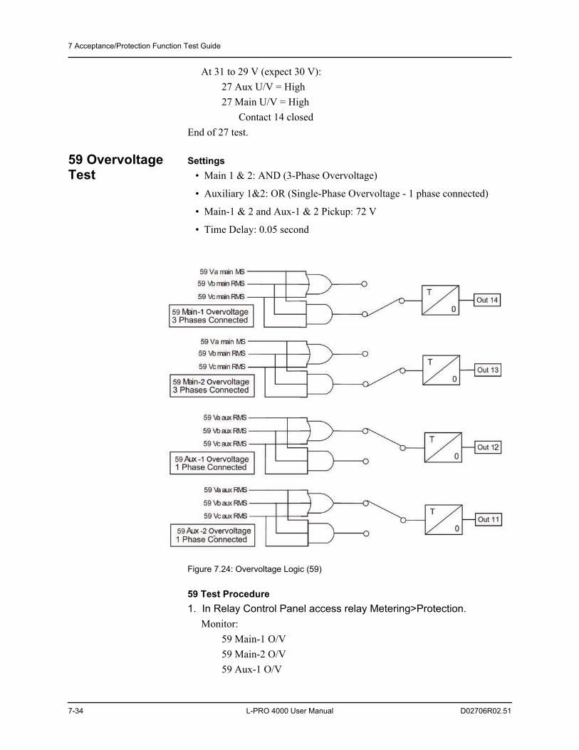
7 Acceptance/Protection Function Test Guide
7-34 L-PRO 4000 User Manual D02706R02.51
At 31 to 29 V (expect 30 V): 27 Aux U/V = High27 Main U/V = High
Contact 14 closedEnd of 27 test.
59 Overvoltage Test
Settings • Main 1 & 2: AND (3-Phase Overvoltage)
• Auxiliary 1&2: OR (Single-Phase Overvoltage - 1 phase connected)
• Main-1 & 2 and Aux-1 & 2 Pickup: 72 V
• Time Delay: 0.05 second
Figure 7.24: Overvoltage Logic (59)
59 Test Procedure1. In Relay Control Panel access relay Metering>Protection.
Monitor:59 Main-1 O/V59 Main-2 O/V59 Aux-1 O/V
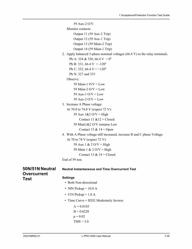
7 Acceptance/Protection Function Test Guide
D02706R02.51 L-PRO 4000 User Manual 7-35
59 Aux-2 O/VMonitor contacts:
Output 11 (59 Aux-2 Trip)Output 12 (59 Aux-1 Trip)Output 13 (59 Main-2 Trip)Output 14 (59 Main-1 Trip)
2. Apply balanced 3-phase nominal voltages (66.4 V) to the relay terminals. Ph A: 324 & 330, 66.4 V < 0 Ph B: 331, 66.4 V < -120 Ph C: 332, 66.4 V < +120 Ph N: 327 and 333Observe:
59 Main-1 O/V = Low59 Main-2 O/V = Low59 Aux-1 O/V = Low59 Aux-2 O/V = Low
3. Increase A Phase voltage:At 70.0 to 74.0 V (expect 72 V):
59 Aux 1&2 O/V = HighContact 11 &12 = Closed
59 Main1&2 O/V remains LowContact 13 & 14 = Open
4. With A Phase voltage still increased, increase B and C phase Voltage.At 70 to 74 V (expect 72 V):
59 Aux 1 & 2 O/V = High59 Main 1 & 2 O/V = High
Contact 13 & 14 = ClosedEnd of 59 test.
50N/51N Neutral Overcurrent Test
Neutral Instantaneous and Time Overcurrent Test
Settings • Both Non-directional
• 50N Pickup = 10.0 A
• 51N Pickup = 1.0 A
• Time Curve = IEEE Moderately Inverse
A = 0.0103B = 0.0228p = 0.02TMS = 3.0
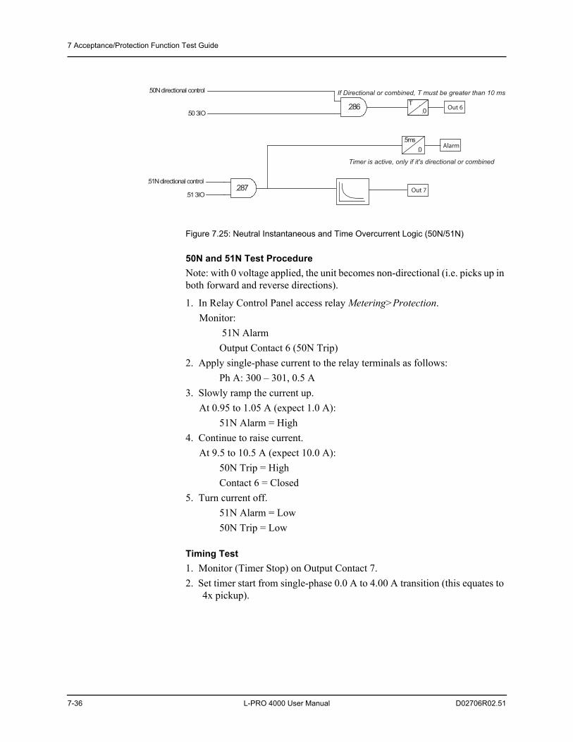
7 Acceptance/Protection Function Test Guide
7-36 L-PRO 4000 User Manual D02706R02.51
Figure 7.25: Neutral Instantaneous and Time Overcurrent Logic (50N/51N)
50N and 51N Test ProcedureNote: with 0 voltage applied, the unit becomes non-directional (i.e. picks up in both forward and reverse directions).
1. In Relay Control Panel access relay Metering>Protection.Monitor:
51N AlarmOutput Contact 6 (50N Trip)
2. Apply single-phase current to the relay terminals as follows:Ph A: 300 – 301, 0.5 A
3. Slowly ramp the current up.At 0.95 to 1.05 A (expect 1.0 A):
51N Alarm = High4. Continue to raise current.
At 9.5 to 10.5 A (expect 10.0 A):50N Trip = High Contact 6 = Closed
5. Turn current off.51N Alarm = Low50N Trip = Low
Timing Test1. Monitor (Timer Stop) on Output Contact 7.2. Set timer start from single-phase 0.0 A to 4.00 A transition (this equates to
4x pickup).
0
50 3IO 286
If Directional or combined, T must be greater than 10 ms
5ms
T
0
Timer is active, only if it's directional or combined
28751 3IO
50N directional control
51N directional control
Out 6
Alarm
Out 7
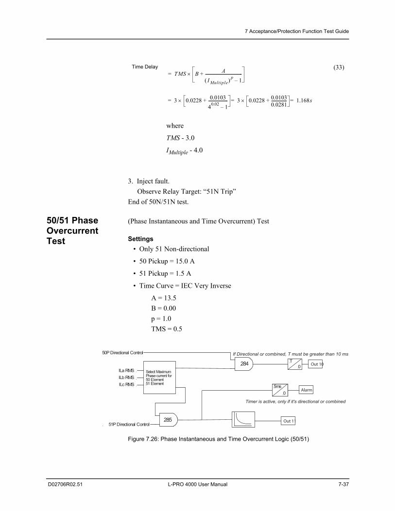
7 Acceptance/Protection Function Test Guide
D02706R02.51 L-PRO 4000 User Manual 7-37
3. Inject fault.Observe Relay Target: “51N Trip”
End of 50N/51N test.
50/51 Phase Overcurrent Test
(Phase Instantaneous and Time Overcurrent) Test
Settings • Only 51 Non-directional
• 50 Pickup = 15.0 A
• 51 Pickup = 1.5 A
• Time Curve = IEC Very Inverse
A = 13.5B = 0.00p = 1.0TMS = 0.5
Figure 7.26: Phase Instantaneous and Time Overcurrent Logic (50/51)
Time Delay
where
TMS - 3.0
IMultiple - 4.0
(33)TMS B A
I Multiple p 1–--------------------------------------+=
3 0.0228 0.010340.02 1–--------------------+ 3 0.0228 0.0103
0.0281----------------+ 1.168s===
0
284
If Directional or combined, T must be greater than 10 ms
5ms
T
0
Timer is active, only if it's directional or combined
285
Select MaximumPhase current for50 Element51 Element
ILa RMS
ILb RMS
ILc RMS
51P Directional Control
50P Directional Control
Out 10
Alarm
Out 11
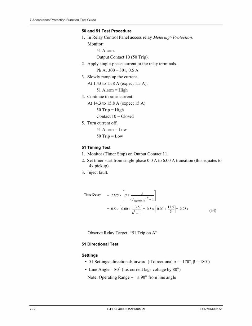
7 Acceptance/Protection Function Test Guide
7-38 L-PRO 4000 User Manual D02706R02.51
50 and 51 Test Procedure1. In Relay Control Panel access relay Metering>Protection.
Monitor:51 Alarm.Output Contact 10 (50 Trip).
2. Apply single-phase current to the relay terminals.Ph A: 300 – 301, 0.5 A
3. Slowly ramp up the current.At 1.43 to 1.58 A (expect 1.5 A):
51 Alarm = High 4. Continue to raise current.
At 14.3 to 15.8 A (expect 15 A):50 Trip = High Contact 10 = Closed
5. Turn current off.51 Alarm = Low50 Trip = Low
51 Timing Test1. Monitor (Timer Stop) on Output Contact 11.2. Set timer start from single-phase 0.0 A to 6.00 A transition (this equates to
4x pickup).3. Inject fault.
Observe Relay Target: “51 Trip on A”
51 Directional Test
Settings • 51 Settings: directional/forward (if directional α = -170º, β = 180º)
• Line Angle = 80 (i.e. current lags voltage by 80)
Note: Operating Range = ± 90 from line angle
Time Delay
(34)
TMS B AI multiple p 1–
-------------------------------------+=
0.5 0.00 13.541 1–--------------+ 0.5 0.00 13.5
3----------+ 2.25s===
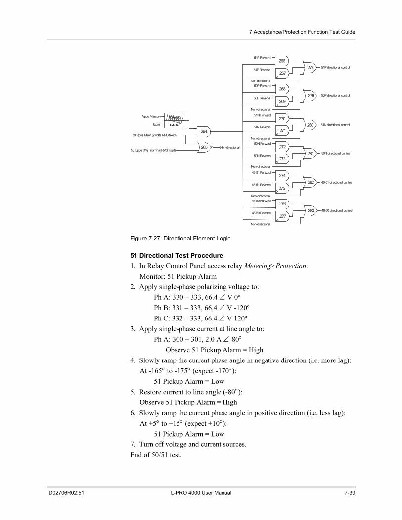
7 Acceptance/Protection Function Test Guide
D02706R02.51 L-PRO 4000 User Manual 7-39
Figure 7.27: Directional Element Logic
51 Directional Test Procedure1. In Relay Control Panel access relay Metering>Protection.
Monitor: 51 Pickup Alarm2. Apply single-phase polarizing voltage to:
Ph A: 330 – 333, 66.4 V 0ºPh B: 331 – 333, 66.4 V -120ºPh C: 332 – 333, 66.4 V 120º
3. Apply single-phase current at line angle to:Ph A: 300 –301, 2.0 A -80
Observe 51 Pickup Alarm = High4. Slowly ramp the current phase angle in negative direction (i.e. more lag):
At -165 to -175 (expect -170):51 Pickup Alarm = Low
5. Restore current to line angle (-80):Observe 51 Pickup Alarm = High
6. Slowly ramp the current phase angle in positive direction (i.e. less lag): At +5 to +15 (expect +10):
51 Pickup Alarm = Low7. Turn off voltage and current sources.End of 50/51 test.
FORWARD
REVERSE
Vpos Memory
ILpos
59 Vpos Main (2 volts RMS fixed)
50 ILpos (4% I nominal RMS fixed)
Non-directional
51P Reverse
51P Forward
Non-directional
50P Reverse
50P Forward
Non-directional
51N Reverse
51N Forward
Non-directional
50N Reverse
50N Forward
Non-directional
46-51 Reverse
46-51 Forward
46-50 Reverse
46-50 Forward
51P directional control
50P directional control
50N directional control
51N directional control
46-51 directional control
46-50 directional control
264
265
266
267
268
269
270
271
272
273
274
275
276
277
278
279
280
281
282
283
Non-directional
Non-directional
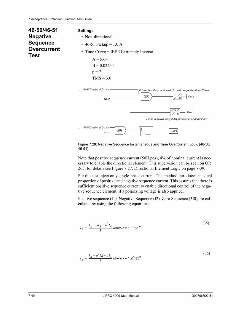
7 Acceptance/Protection Function Test Guide
7-40 L-PRO 4000 User Manual D02706R02.51
46-50/46-51 Negative Sequence Overcurrent Test
Settings • Non-directional
• 46-51 Pickup = 1.0 A
• Time Curve = IEEE Extremely Inverse
A = 5.64B = 0.02434p = 2TMS = 3.0
Figure 7.28: Negative Sequence Instantaneous and Time OverCurrent Logic (46-50/46-51)
Note that positive sequence current (50ILpos), 4% of nominal current is nec-essary to enable the directional element. This supervision can be seen on OR 265, for details see Figure 7.27: Directional Element Logic on page 7-39.
For this test inject only single-phase current. This method introduces an equal proportion of positive and negative sequence current. This assures that there is sufficient positive sequence current to enable directional control of the nega-tive sequence element, if a polarizing voltage is also applied.
Positive sequence (I1), Negative Sequence (I2), Zero Sequence (3I0) are cal-culated by using the following equations:
where a = 1 120(35)
where a = 1 120(36)
0
50 I2288
51 I1
If Directional or combined, T must be greater than 10 ms
5ms
T
0
289
46-50 Directional Control
46-51 Directional Control
Timer is active, only if it's directional or combined
Out 8
Alarm
Out 9
I 1I A aI B a2I C+ +
3---------------------------------------=
I 2I A a2I B aI C+ +
3---------------------------------------=
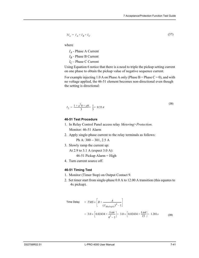
7 Acceptance/Protection Function Test Guide
D02706R02.51 L-PRO 4000 User Manual 7-41
where
IA - Phase A CurrentIB - Phase B CurrentIC - Phase C Current
Using Equation 6 notice that there is a need to triple the pickup setting current on one phase to obtain the pickup value of negative sequence current.
For example injecting 1.0 A on Phase A only (Phase B = Phase C = 0), and with no voltage applied, the 46-51 element becomes non-directional even though the setting is directional:
46-51 Test Procedure1. In Relay Control Panel access relay Metering>Protection.
Monitor: 46-51 Alarm2. Apply single-phase current to the relay terminals as follows:
Ph A: 300 – 301, 2.5 A3. Slowly ramp the current up:
At 2.9 to 3.1 A (expect 3.0 A):46-51 Pickup Alarm = High
4. Turn current source off.
46-51 Timing Test1. Monitor (Timer Stop) on Output Contact 9.2. Set timer start from single-phase 0.0 A to 12.00 A transition (this equates to
4x pickup).
(37)
(38)
Time Delay
(39)
3I o I A I B I C+ +=
I21 a20 a0+ +
3------------------------------- 1
3--- 0.33A===
TMS B AIMultiple p 1–
--------------------------------------+=
3.0 0.02434 5.6442 1–--------------+ 3.0 0.02434 5.64
15----------+ 1.201s===
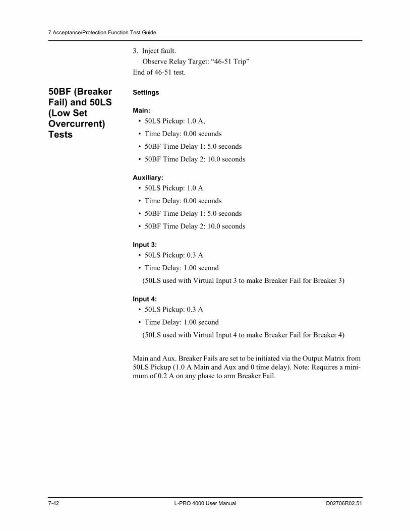
7 Acceptance/Protection Function Test Guide
7-42 L-PRO 4000 User Manual D02706R02.51
3. Inject fault.Observe Relay Target: “46-51 Trip”
End of 46-51 test.
50BF (Breaker Fail) and 50LS (Low Set Overcurrent) Tests
Settings
Main: • 50LS Pickup: 1.0 A,
• Time Delay: 0.00 seconds
• 50BF Time Delay 1: 5.0 seconds
• 50BF Time Delay 2: 10.0 seconds
Auxiliary: • 50LS Pickup: 1.0 A
• Time Delay: 0.00 seconds
• 50BF Time Delay 1: 5.0 seconds
• 50BF Time Delay 2: 10.0 seconds
Input 3: • 50LS Pickup: 0.3 A
• Time Delay: 1.00 second
(50LS used with Virtual Input 3 to make Breaker Fail for Breaker 3)
Input 4: • 50LS Pickup: 0.3 A
• Time Delay: 1.00 second
(50LS used with Virtual Input 4 to make Breaker Fail for Breaker 4)
Main and Aux. Breaker Fails are set to be initiated via the Output Matrix from 50LS Pickup (1.0 A Main and Aux and 0 time delay). Note: Requires a mini-mum of 0.2 A on any phase to arm Breaker Fail.
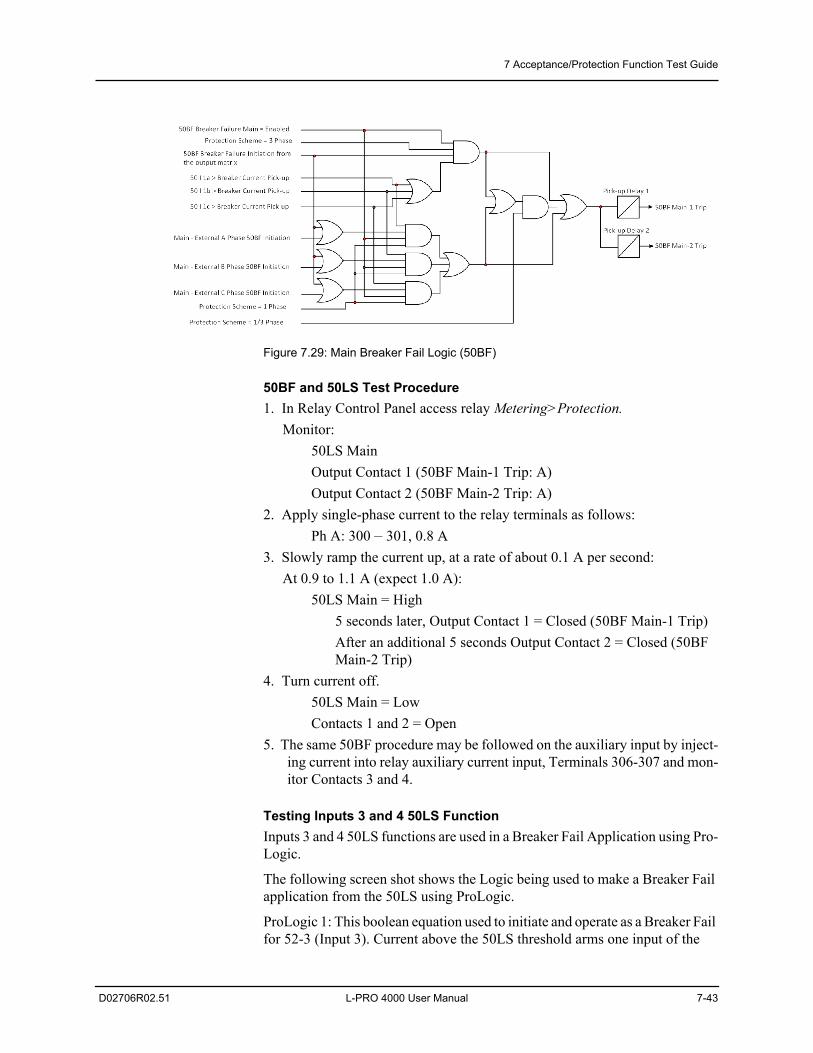
7 Acceptance/Protection Function Test Guide
D02706R02.51 L-PRO 4000 User Manual 7-43
Figure 7.29: Main Breaker Fail Logic (50BF)
50BF and 50LS Test Procedure1. In Relay Control Panel access relay Metering>Protection.
Monitor:50LS MainOutput Contact 1 (50BF Main-1 Trip: A)Output Contact 2 (50BF Main-2 Trip: A)
2. Apply single-phase current to the relay terminals as follows:Ph A: 300 –301, 0.8 A
3. Slowly ramp the current up, at a rate of about 0.1 A per second: At 0.9 to 1.1 A (expect 1.0 A):
50LS Main = High5 seconds later, Output Contact 1 = Closed (50BF Main-1 Trip)After an additional 5 seconds Output Contact 2 = Closed (50BF Main-2 Trip)
4. Turn current off.50LS Main = LowContacts 1 and 2 = Open
5. The same 50BF procedure may be followed on the auxiliary input by inject-ing current into relay auxiliary current input, Terminals 306-307 and mon-itor Contacts 3 and 4.
Testing Inputs 3 and 4 50LS FunctionInputs 3 and 4 50LS functions are used in a Breaker Fail Application using Pro-Logic.
The following screen shot shows the Logic being used to make a Breaker Fail application from the 50LS using ProLogic.
ProLogic 1: This boolean equation used to initiate and operate as a Breaker Fail for 52-3 (Input 3). Current above the 50LS threshold arms one input of the
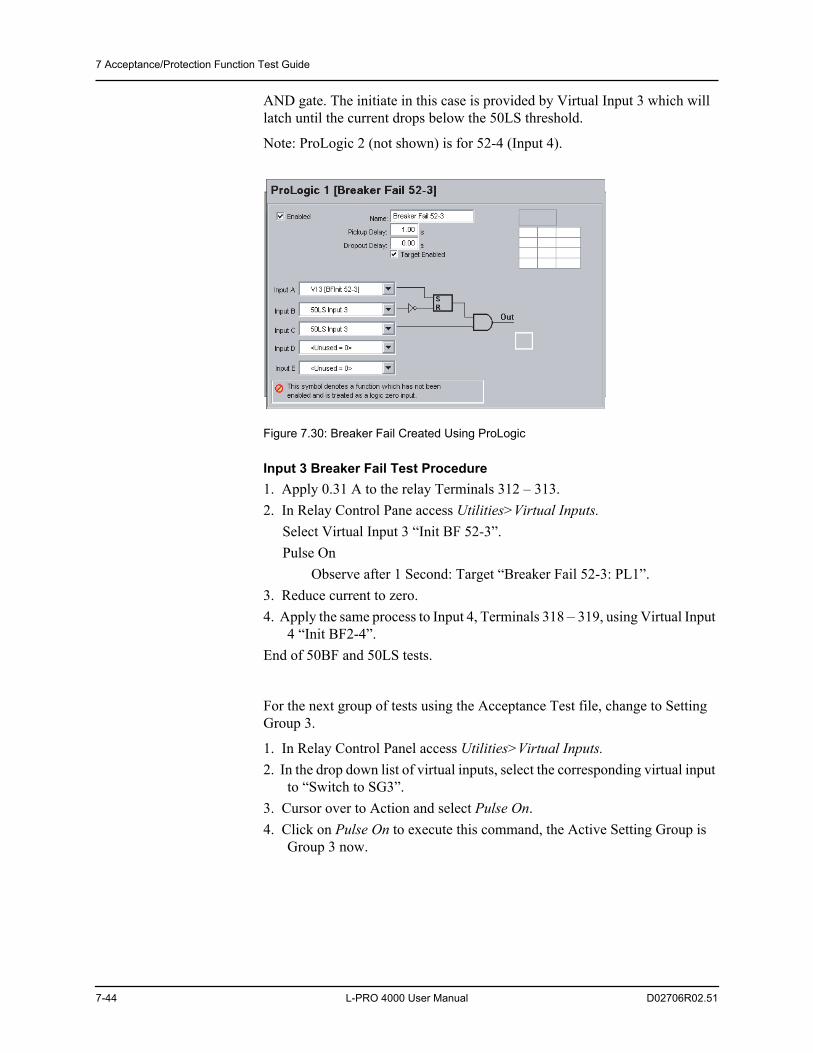
7 Acceptance/Protection Function Test Guide
7-44 L-PRO 4000 User Manual D02706R02.51
AND gate. The initiate in this case is provided by Virtual Input 3 which will latch until the current drops below the 50LS threshold.
Note: ProLogic 2 (not shown) is for 52-4 (Input 4).
Figure 7.30: Breaker Fail Created Using ProLogic
Input 3 Breaker Fail Test Procedure1. Apply 0.31 A to the relay Terminals 312 – 313.2. In Relay Control Pane access Utilities>Virtual Inputs.
Select Virtual Input 3 “Init BF 52-3”.Pulse On
Observe after 1 Second: Target “Breaker Fail 52-3: PL1”.3. Reduce current to zero.4. Apply the same process to Input 4, Terminals 318 –319, using Virtual Input
4 “Init BF2-4”.End of 50BF and 50LS tests.
For the next group of tests using the Acceptance Test file, change to Setting Group 3.
1. In Relay Control Panel access Utilities>Virtual Inputs.2. In the drop down list of virtual inputs, select the corresponding virtual input
to “Switch to SG3”.3. Cursor over to Action and select Pulse On. 4. Click on Pulse On to execute this command, the Active Setting Group is
Group 3 now.
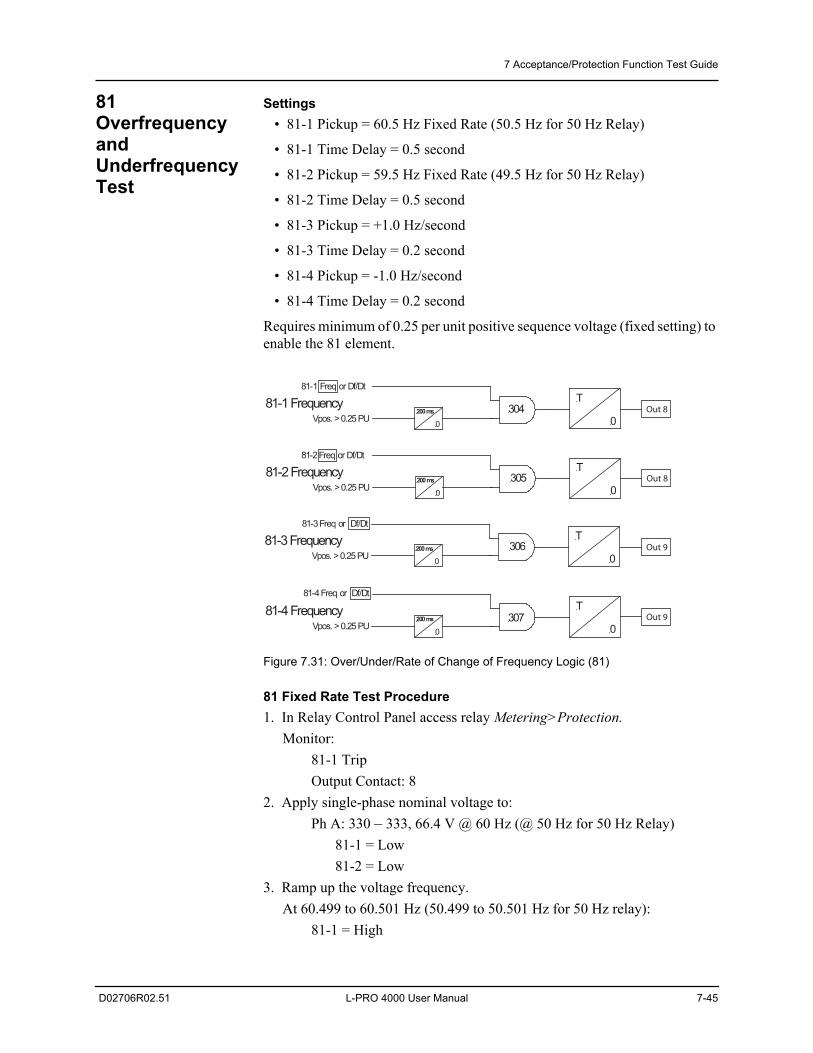
7 Acceptance/Protection Function Test Guide
D02706R02.51 L-PRO 4000 User Manual 7-45
81 Overfrequency and Underfrequency Test
Settings • 81-1 Pickup = 60.5 Hz Fixed Rate (50.5 Hz for 50 Hz Relay)
• 81-1 Time Delay = 0.5 second
• 81-2 Pickup = 59.5 Hz Fixed Rate (49.5 Hz for 50 Hz Relay)
• 81-2 Time Delay = 0.5 second
• 81-3 Pickup = +1.0 Hz/second
• 81-3 Time Delay = 0.2 second
• 81-4 Pickup = -1.0 Hz/second
• 81-4 Time Delay = 0.2 second
Requires minimum of 0.25 per unit positive sequence voltage (fixed setting) to enable the 81 element.
Figure 7.31: Over/Under/Rate of Change of Frequency Logic (81)
81 Fixed Rate Test Procedure1. In Relay Control Panel access relay Metering>Protection.
Monitor:81-1 TripOutput Contact: 8
2. Apply single-phase nominal voltage to:Ph A: 330 – 333, 66.4 V @ 60 Hz (@ 50 Hz for 50 Hz Relay)
81-1 = Low81-2 = Low
3. Ramp up the voltage frequency.At 60.499 to 60.501 Hz (50.499 to 50.501 Hz for 50 Hz relay):
81-1 = High
81-1 FrequencyVpos. > 0.25 PU
304200 ms
0
T
0
81-2 FrequencyVpos. > 0.25 PU
305
81-2 Freq or Df/Dt
T
0
81-3 FrequencyVpos. > 0.25 PU
306
81-3 Freq or Df/Dt
T
0
81-4 FrequencyVpos. > 0.25 PU
307
81-4 Freq or Df/Dt
T
0
200 ms
0
200 ms
0
200 ms
0
81-1 Freq or Df/Dt
Out 8
Out 8
Out 9
Out 9
7 Acceptance/Protection Function Test Guide
7-46 L-PRO 4000 User Manual D02706R02.51
81-2 = LowContact 8 = Closed
4. Ramp down the voltage frequency.At 59.501 to 59.499 Hz (49.501 to 49.499 Hz for 50 Hz Relay):
81-1 = Low81-2 = HighContact 8 = Closed
5. Turn voltage source off.
81 Rate of Change (df/dt) Test Procedure1. In Relay Control Panel access relay Metering>Protection.
Monitor:81-3 TripContact: 9
2. Apply single-phase nominal voltage to the relay terminals.Ph A: 330 – 333, 66.4 V @ 60 Hz (50 Hz for 50 Hz Relay)
81-3 = Low81-4 = Low
3. Ramp the frequency at a rate of +0.99 Hz/s for a duration of 2 seconds.Observe:
81-3 = Low81-4 = LowContact 9 = Open
4. Restore nominal frequency.5. Ramp the frequency at a rate of +1.01 Hz/s for a duration of 2 seconds.
Observe:81-3 = High81-4 = LowContact 9 = Closed
6. Restore nominal frequency.7. Ramp the frequency at a rate of -0.99 Hz/s of a duration of 2 seconds.
Observe:81-3 = Low81-4 = LowContact 9 = Open
8. Restore nominal frequency.9. Ramp the frequency at a rate of -1.01 Hz/s for a duration of 2 seconds.
Observe:81-3 = Low81-4 = HighContact 9 = Closed
7 Acceptance/Protection Function Test Guide
D02706R02.51 L-PRO 4000 User Manual 7-47
81 Timing Test Procedure1. Monitor (Timer Stop) on Output Contact 8 (81-1).2. Set timer start on instantaneous frequency shift 66.4 V @ 60 Hz to 60.6 Hz
transition.Expect time delay of 500 ms + approximately 1.5 cycle detection time.
3. Apply the frequency shift.Confirm the expected time delay.
Target “81-1”4. Move (Timer Stop) to Output Contact 9 (81-2).5. Set timer start on instantaneous frequency shift 66.4 V @ 60 Hz to 59.4 Hz
transition.Expect time delay of 500 ms + approximately 1.5 cycle detection time.
6. Apply the frequency shift.Confirm the expected time delay.
Target “81-2”End of 81 test.
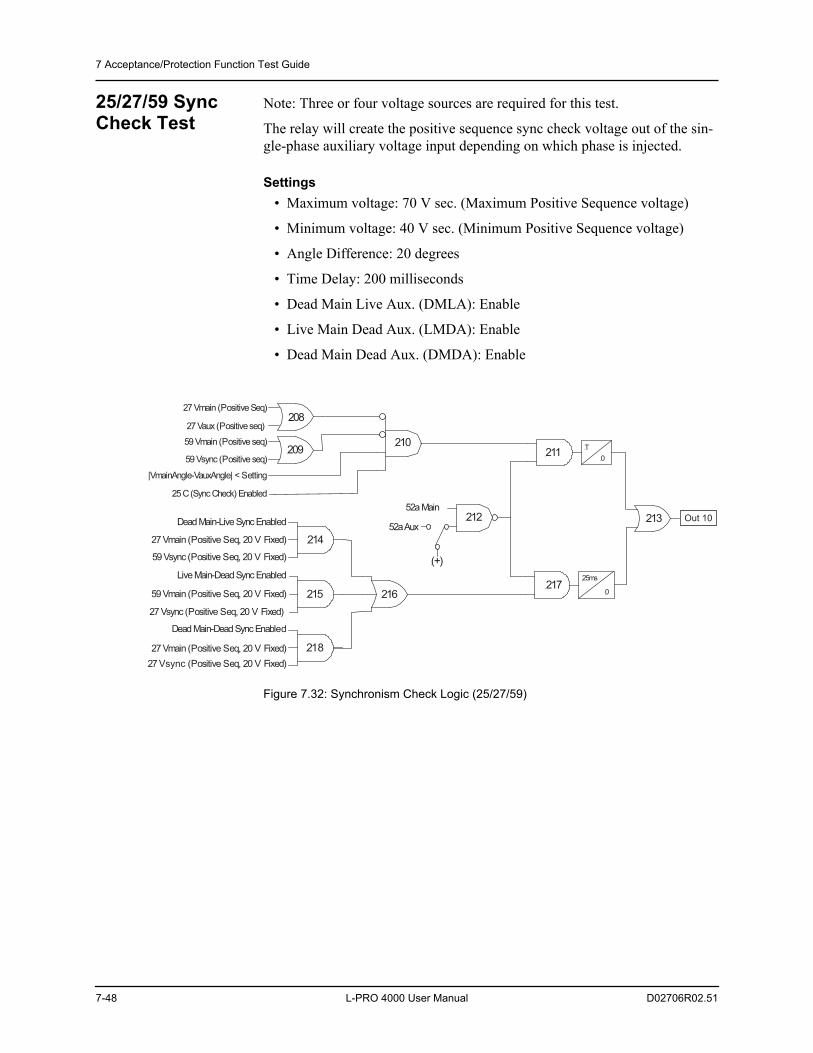
7 Acceptance/Protection Function Test Guide
7-48 L-PRO 4000 User Manual D02706R02.51
25/27/59 Sync Check Test
Note: Three or four voltage sources are required for this test.
The relay will create the positive sequence sync check voltage out of the sin-gle-phase auxiliary voltage input depending on which phase is injected.
Settings • Maximum voltage: 70 V sec. (Maximum Positive Sequence voltage)
• Minimum voltage: 40 V sec. (Minimum Positive Sequence voltage)
• Angle Difference: 20 degrees
• Time Delay: 200 milliseconds
• Dead Main Live Aux. (DMLA): Enable
• Live Main Dead Aux. (LMDA): Enable
• Dead Main Dead Aux. (DMDA): Enable
Figure 7.32: Synchronism Check Logic (25/27/59)
27 Vmain (Positive Seq, 20 V Fixed)
216
213
Dead Main-Dead Sync Enabled
59 Vmain (Positive Seq, 20 V Fixed)
27 Vsync (Positive Seq, 20 V Fixed)
215
Live Main-Dead Sync Enabled
27 Vmain (Positive Seq, 20 V Fixed)
59 Vsync (Positive Seq, 20 V Fixed)
214
Dead Main-Live Sync Enabled
27 Vmain (Positive Seq)208
27 Vaux (Positive seq)
59 Vmain (Positive seq)209
59 Vsync (Positive seq)
210
|VmainAngle-VauxAngle| < Setting
25 C (Sync Check) Enabled
T
0
25ms
0
211
21252a Main
52a Aux
(+)
217
Out 10
218
27 Vsync (Positive Seq, 20 V Fixed)
7 Acceptance/Protection Function Test Guide
D02706R02.51 L-PRO 4000 User Manual 7-49
Sync Check Test Procedure1. In Relay Control Panel access relay Metering>Protection.
Monitor: 25/27/59 Sync CheckOutput Contact: 10Observe 25/27/59 Sync Check = High (Proves DMDA with no voltage
applied)2. Apply voltages to the relay main voltage input terminals sufficient to create
Vpos of 66.4 V.If only 3 voltage sources are available:
Ph A: 330, 99.6 V 0Ph B: 331, 99.6 V -120Ph C: 332, not applicablePh N: 333
OR
If 4 voltage sources are available:Ph A: 330, 66.4 V 0Ph B: 331, 66.4 V -120Ph C: 332, 66.4 V +120Ph N: 333
Observe 25/27/59 Sync Check = High (Proves Live Main Dead Aux (LM-DA) with only line voltage applied)
3. Turn voltage off.4. Apply single-phase nominal voltage (120 V) to the relay auxiliary voltage
input terminals.Ph A:324, 120 V 25 (Note: 3x Minimum Voltage = 3x40 =120 V
this is for single-phase only)Ph N: 327(Short and ground unused Terminals 325 and 326)Observe 25/27/59 Sync Check = High (Proves DMLA with only bus-voltage applied)
5. Apply both sets of voltages to main and auxiliary inputs as detailed above.Observe:
25/27/59 Sync Check = Low6. Simultaneously rotate the auxiliary voltage phase angle in lagging direction
(i.e. toward 0).At 21 to 19 difference (expect 20):
25/27/59 = HighContact 10 = Closed (after 200 ms)
7. Slowly ramp down the auxiliary voltage magnitude.At 41.0 to 39.0 V (expect 40 V):
25/27/59 = Low
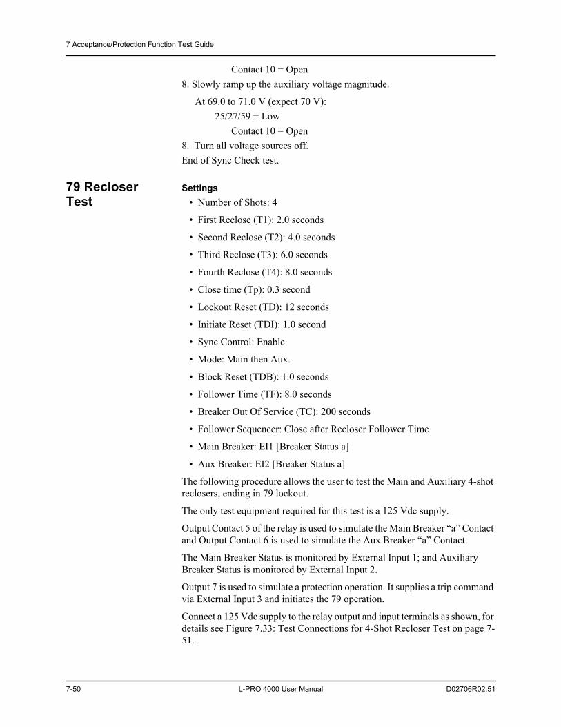
7 Acceptance/Protection Function Test Guide
7-50 L-PRO 4000 User Manual D02706R02.51
Contact 10 = Open8. Slowly ramp up the auxiliary voltage magnitude.
At 69.0 to 71.0 V (expect 70 V):25/27/59 = Low
Contact 10 = Open8. Turn all voltage sources off.End of Sync Check test.
79 Recloser Test
Settings • Number of Shots: 4
• First Reclose (T1): 2.0 seconds
• Second Reclose (T2): 4.0 seconds
• Third Reclose (T3): 6.0 seconds
• Fourth Reclose (T4): 8.0 seconds
• Close time (Tp): 0.3 second
• Lockout Reset (TD): 12 seconds
• Initiate Reset (TDI): 1.0 second
• Sync Control: Enable
• Mode: Main then Aux.
• Block Reset (TDB): 1.0 seconds
• Follower Time (TF): 8.0 seconds
• Breaker Out Of Service (TC): 200 seconds
• Follower Sequencer: Close after Recloser Follower Time
• Main Breaker: EI1 [Breaker Status a]
• Aux Breaker: EI2 [Breaker Status a]
The following procedure allows the user to test the Main and Auxiliary 4-shot reclosers, ending in 79 lockout.
The only test equipment required for this test is a 125 Vdc supply.
Output Contact 5 of the relay is used to simulate the Main Breaker “a” Contact and Output Contact 6 is used to simulate the Aux Breaker “a” Contact.
The Main Breaker Status is monitored by External Input 1; and Auxiliary Breaker Status is monitored by External Input 2.
Output 7 is used to simulate a protection operation. It supplies a trip command via External Input 3 and initiates the 79 operation.
Connect a 125 Vdc supply to the relay output and input terminals as shown, for details see Figure 7.33: Test Connections for 4-Shot Recloser Test on page 7-51.
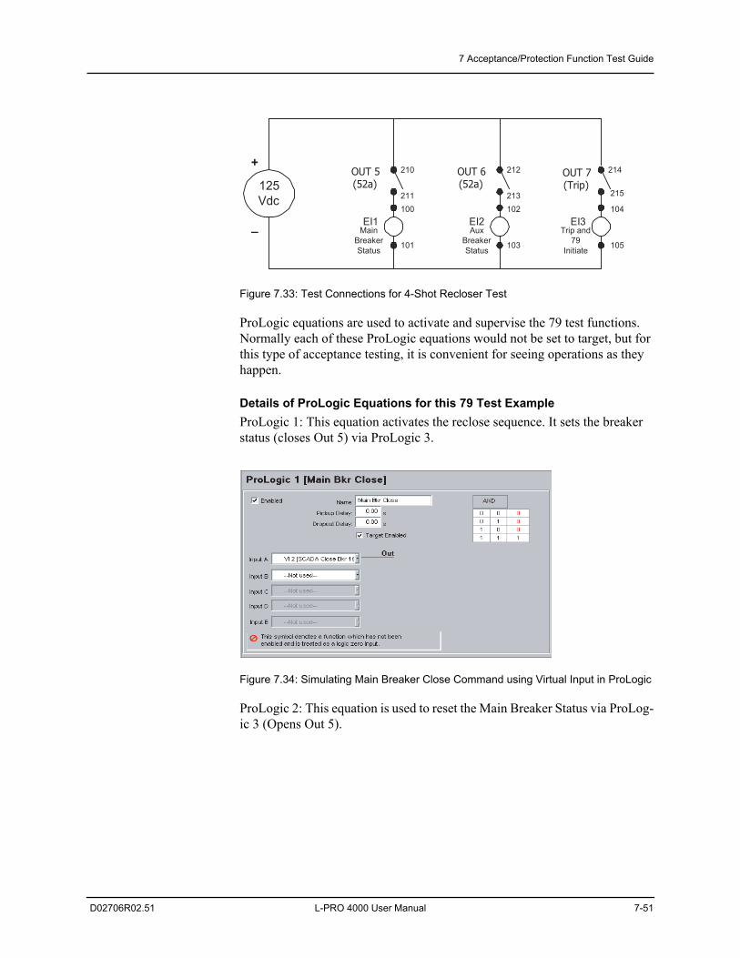
7 Acceptance/Protection Function Test Guide
D02706R02.51 L-PRO 4000 User Manual 7-51
Figure 7.33: Test Connections for 4-Shot Recloser Test
ProLogic equations are used to activate and supervise the 79 test functions. Normally each of these ProLogic equations would not be set to target, but for this type of acceptance testing, it is convenient for seeing operations as they happen.
Details of ProLogic Equations for this 79 Test ExampleProLogic 1: This equation activates the reclose sequence. It sets the breaker status (closes Out 5) via ProLogic 3.
Figure 7.34: Simulating Main Breaker Close Command using Virtual Input in ProLogic
ProLogic 2: This equation is used to reset the Main Breaker Status via ProLog-ic 3 (Opens Out 5).
125Vdc
+
_ EI2 EI3
OUT 6(52a)
OUT 7(Trip)
212
213102
103
104
105
214
215
AuxBreakerStatus
Trip and79
Initiate
EI1
OUT 5(52a)
210
211100
101
MainBreakerStatus
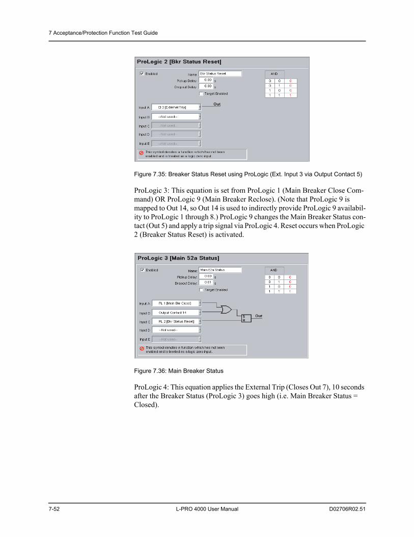
7 Acceptance/Protection Function Test Guide
7-52 L-PRO 4000 User Manual D02706R02.51
Figure 7.35: Breaker Status Reset using ProLogic (Ext. Input 3 via Output Contact 5)
ProLogic 3: This equation is set from ProLogic 1 (Main Breaker Close Com-mand) OR ProLogic 9 (Main Breaker Reclose). (Note that ProLogic 9 is mapped to Out 14, so Out 14 is used to indirectly provide ProLogic 9 availabil-ity to ProLogic 1 through 8.) ProLogic 9 changes the Main Breaker Status con-tact (Out 5) and apply a trip signal via ProLogic 4. Reset occurs when ProLogic 2 (Breaker Status Reset) is activated.
Figure 7.36: Main Breaker Status
ProLogic 4: This equation applies the External Trip (Closes Out 7), 10 seconds after the Breaker Status (ProLogic 3) goes high (i.e. Main Breaker Status = Closed).
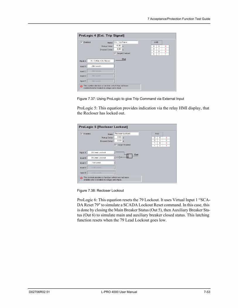
7 Acceptance/Protection Function Test Guide
D02706R02.51 L-PRO 4000 User Manual 7-53
Figure 7.37: Using ProLogic to give Trip Command via External Input
ProLogic 5: This equation provides indication via the relay HMI display, that the Recloser has locked out.
Figure 7.38: Recloser Lockout
ProLogic 6: This equation resets the 79 Lockout. It uses Virtual Input 1 “SCA-DA Reset 79" to simulate a SCADA Lockout Reset command. In this case, this is done by closing the Main Breaker Status (Out 5), then Auxiliary Breaker Sta-tus (Out 6) to simulate main and auxiliary breaker closed status. This latching function resets when the 79 Lead Lockout goes low.
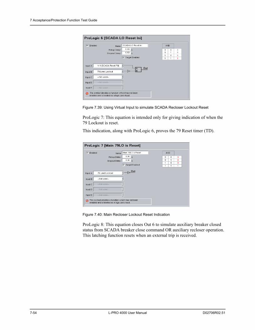
7 Acceptance/Protection Function Test Guide
7-54 L-PRO 4000 User Manual D02706R02.51
Figure 7.39: Using Virtual Input to simulate SCADA Recloser Lockout Reset
ProLogic 7: This equation is intended only for giving indication of when the 79 Lockout is reset.
This indication, along with ProLogic 6, proves the 79 Reset timer (TD).
Figure 7.40: Main Recloser Lockout Reset Indication
ProLogic 8: This equation closes Out 6 to simulate auxiliary breaker closed status from SCADA breaker close command OR auxiliary recloser operation. This latching function resets when an external trip is received.
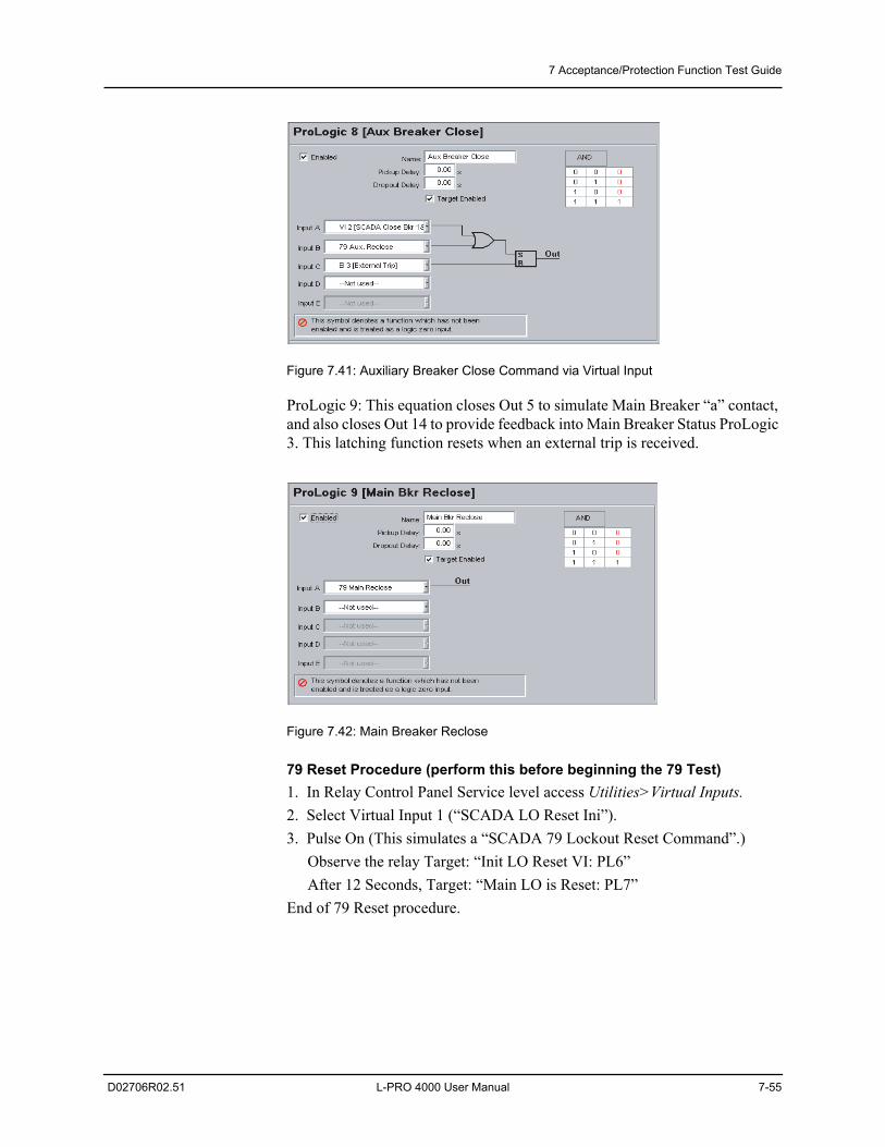
7 Acceptance/Protection Function Test Guide
D02706R02.51 L-PRO 4000 User Manual 7-55
Figure 7.41: Auxiliary Breaker Close Command via Virtual Input
ProLogic 9: This equation closes Out 5 to simulate Main Breaker “a” contact, and also closes Out 14 to provide feedback into Main Breaker Status ProLogic 3. This latching function resets when an external trip is received.
Figure 7.42: Main Breaker Reclose
79 Reset Procedure (perform this before beginning the 79 Test)1. In Relay Control Panel Service level access Utilities>Virtual Inputs.2. Select Virtual Input 1 (“SCADA LO Reset Ini”). 3. Pulse On (This simulates a “SCADA 79 Lockout Reset Command”.)
Observe the relay Target: “Init LO Reset VI: PL6”After 12 Seconds, Target: “Main LO is Reset: PL7”
End of 79 Reset procedure.
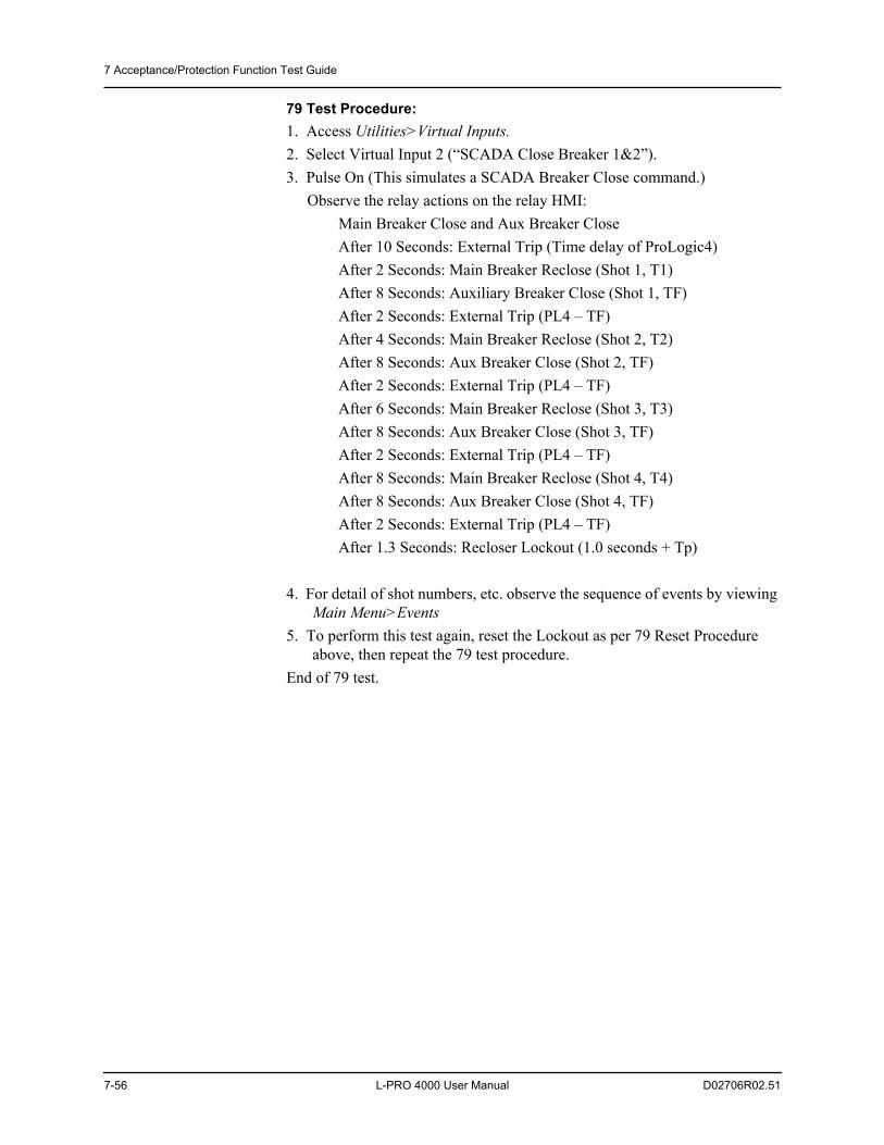
7 Acceptance/Protection Function Test Guide
7-56 L-PRO 4000 User Manual D02706R02.51
79 Test Procedure:1. Access Utilities>Virtual Inputs.2. Select Virtual Input 2 (“SCADA Close Breaker 1&2”).3. Pulse On (This simulates a SCADA Breaker Close command.)
Observe the relay actions on the relay HMI:Main Breaker Close and Aux Breaker CloseAfter 10 Seconds: External Trip (Time delay of ProLogic4)After 2 Seconds: Main Breaker Reclose (Shot 1, T1)After 8 Seconds: Auxiliary Breaker Close (Shot 1, TF)After 2 Seconds: External Trip (PL4 – TF)After 4 Seconds: Main Breaker Reclose (Shot 2, T2)After 8 Seconds: Aux Breaker Close (Shot 2, TF)After 2 Seconds: External Trip (PL4 – TF)After 6 Seconds: Main Breaker Reclose (Shot 3, T3)After 8 Seconds: Aux Breaker Close (Shot 3, TF)After 2 Seconds: External Trip (PL4 – TF)After 8 Seconds: Main Breaker Reclose (Shot 4, T4)After 8 Seconds: Aux Breaker Close (Shot 4, TF)After 2 Seconds: External Trip (PL4 – TF)After 1.3 Seconds: Recloser Lockout (1.0 seconds + Tp)
4. For detail of shot numbers, etc. observe the sequence of events by viewing Main Menu>Events
5. To perform this test again, reset the Lockout as per 79 Reset Procedure above, then repeat the 79 test procedure.
End of 79 test.
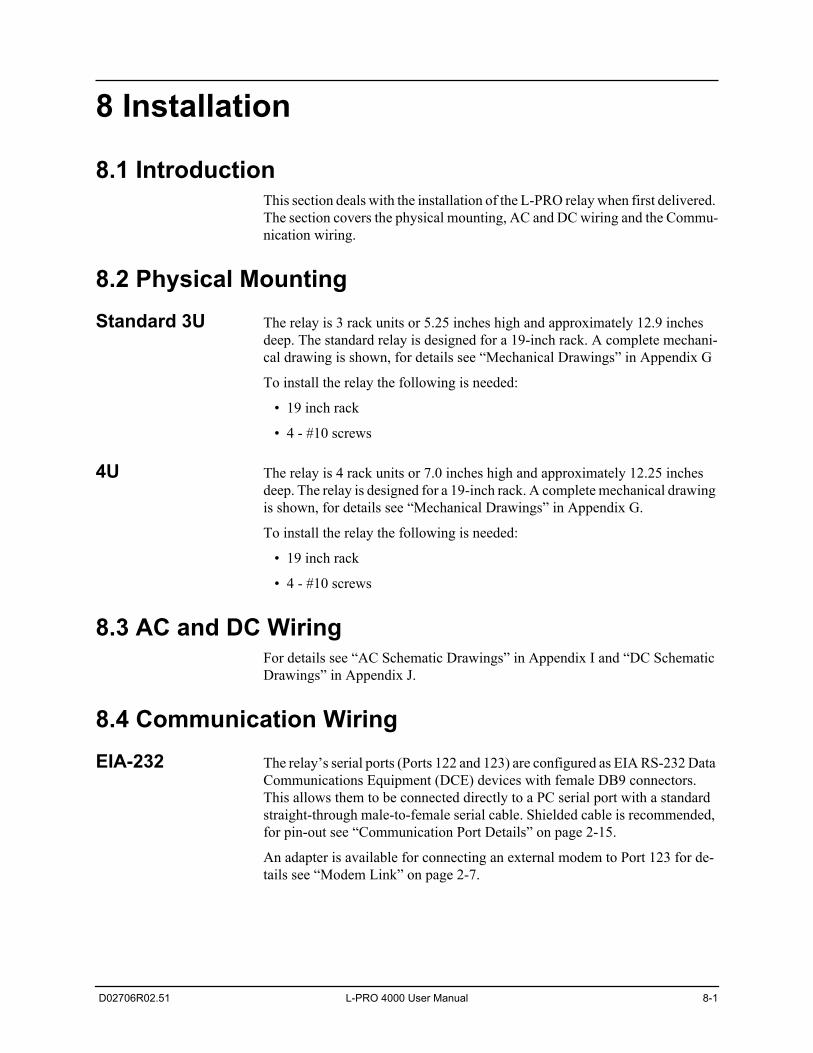
D02706R02.51 L-PRO 4000 User Manual 8-1
8 Installation
8.1 IntroductionThis section deals with the installation of the L-PRO relay when first delivered. The section covers the physical mounting, AC and DC wiring and the Commu-nication wiring.
8.2 Physical MountingStandard 3U The relay is 3 rack units or 5.25 inches high and approximately 12.9 inches
deep. The standard relay is designed for a 19-inch rack. A complete mechani-cal drawing is shown, for details see “Mechanical Drawings” in Appendix G
To install the relay the following is needed:
• 19 inch rack
• 4 - #10 screws
4U The relay is 4 rack units or 7.0 inches high and approximately 12.25 inches deep. The relay is designed for a 19-inch rack. A complete mechanical drawing is shown, for details see “Mechanical Drawings” in Appendix G.
To install the relay the following is needed:
• 19 inch rack
• 4 - #10 screws
8.3 AC and DC WiringFor details see “AC Schematic Drawings” in Appendix I and “DC Schematic Drawings” in Appendix J.
8.4 Communication WiringEIA-232 The relay’s serial ports (Ports 122 and 123) are configured as EIA RS-232 Data
Communications Equipment (DCE) devices with female DB9 connectors. This allows them to be connected directly to a PC serial port with a standard straight-through male-to-female serial cable. Shielded cable is recommended, for pin-out see “Communication Port Details” on page 2-15.
An adapter is available for connecting an external modem to Port 123 for de-tails see “Modem Link” on page 2-7.
8 Installation
8-2 L-PRO 4000 User Manual D02706R02.51
RJ-45 There is one front 100BASE-T Ethernet Port 119 with RJ-45 receptacle. Use CAT5 or CAT5e straight. The rear Ethernet Ports 119 and 120 may also be configured as 100BASE-T Ethernet Ports.
Optical ST Port 119 and port 120 in the rear panel may be configured with ST style optical connectors if desired. These are 1300 nm 100BASE-FX optical Ethernet ports. The transmit and receive connections are indicated on the rear panel. Use stan-dard multi-mode cables with ST connectors for this interface.
USB There is a standard USB-B connector on the front panel. This is a USB 2.0 Full Speed interface and can be connected to a PC with a standard USB peripheral cable (A style to B style).
RJ-11 The relay may have an optional internal modem. Connection to this is via the relay’s Port 118 RJ-11 receptacle. A standard telephone extension cable is to be used.
IRIG-B Wiring The relay accepts both modulated and unmodulated IRIG-B standard time sig-nals with or without the IEEE 1344 extensions. The IRIG-B connector on the back of the relay is BNC type.
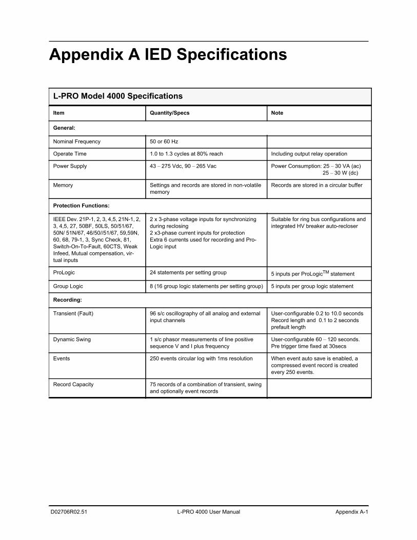
D02706R02.51 L-PRO 4000 User Manual Appendix A-1
Appendix A IED Specifications
L-PRO Model 4000 Specifications
Item Quantity/Specs Note
General:
Nominal Frequency 50 or 60 Hz
Operate Time 1.0 to 1.3 cycles at 80% reach Including output relay operation
Power Supply 43 – 275 Vdc, 90 – 265 Vac Power Consumption: 25 – 30 VA (ac) 25 – 30 W (dc)
Memory Settings and records are stored in non-volatile memory
Records are stored in a circular buffer
Protection Functions:
IEEE Dev. 21P-1, 2, 3, 4,5, 21N-1, 2, 3, 4,5, 27, 50BF, 50LS, 50/51/67, 50N/ 51N/67, 46/50//51/67, 59,59N, 60, 68, 79-1, 3, Sync Check, 81, Switch-On-To-Fault, 60CTS, Weak Infeed, Mutual compensation, vir-tual inputs
2 x 3-phase voltage inputs for synchronizing during reclosing2 x3-phase current inputs for protectionExtra 6 currents used for recording and Pro-Logic input
Suitable for ring bus configurations and integrated HV breaker auto-recloser
ProLogic 24 statements per setting group 5 inputs per ProLogicTM statement
Group Logic 8 (16 group logic statements per setting group) 5 inputs per group logic statement
Recording:
Transient (Fault) 96 s/c oscillography of all analog and external input channels
User-configurable 0.2 to 10.0 secondsRecord length and 0.1 to 2 seconds prefault length
Dynamic Swing 1 s/c phasor measurements of line positive sequence V and I plus frequency
User-configurable 60 – 120 seconds. Pre trigger time fixed at 30secs
Events 250 events circular log with 1ms resolution When event auto save is enabled, a compressed event record is created every 250 events.
Record Capacity 75 records of a combination of transient, swing and optionally event records
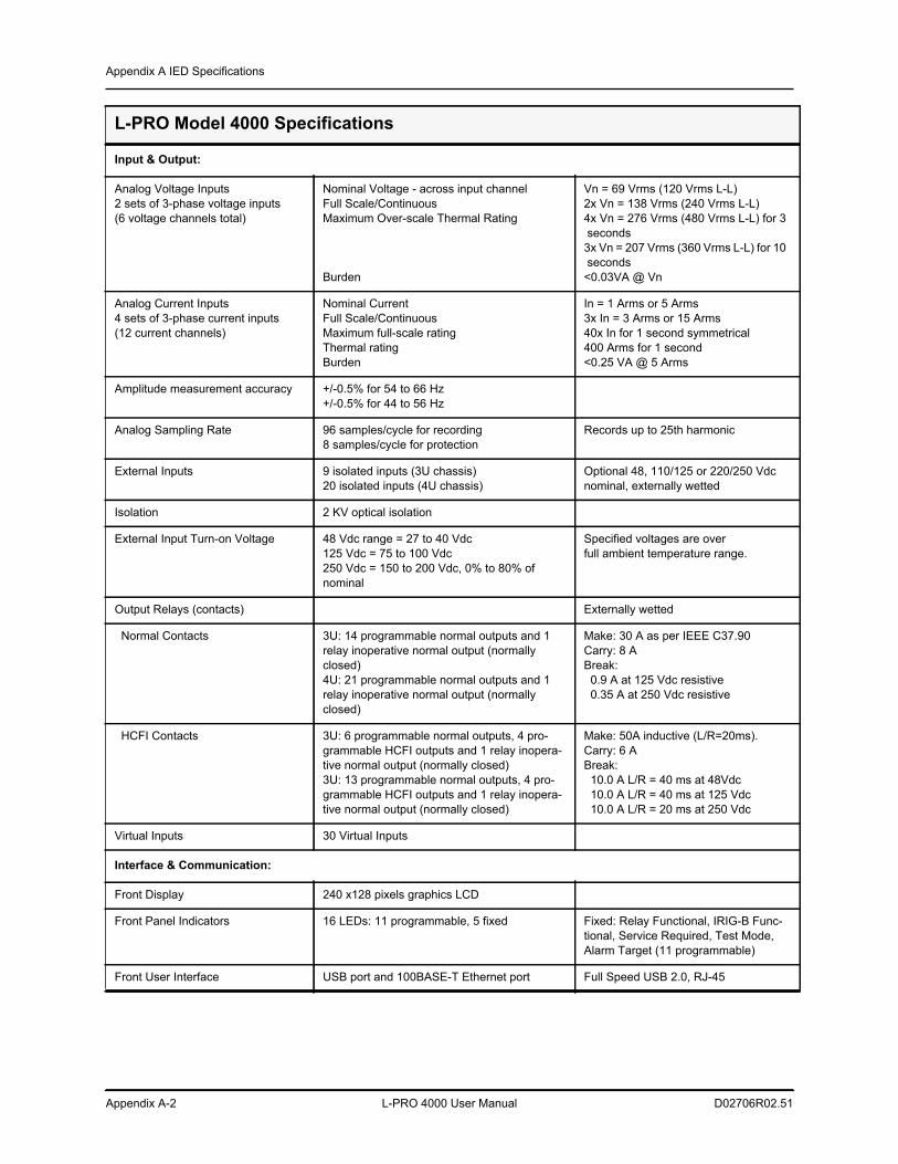
Appendix A IED Specifications
Appendix A-2 L-PRO 4000 User Manual D02706R02.51
Input & Output:
Analog Voltage Inputs2 sets of 3-phase voltage inputs(6 voltage channels total)
Nominal Voltage - across input channelFull Scale/ContinuousMaximum Over-scale Thermal Rating
Burden
Vn = 69 Vrms (120 Vrms L-L)2x Vn = 138 Vrms (240 Vrms L-L)4x Vn = 276 Vrms (480 Vrms L-L) for 3 seconds3x Vn = 207 Vrms (360 Vrms L-L) for 10 seconds<0.03VA @ Vn
Analog Current Inputs4 sets of 3-phase current inputs (12 current channels)
Nominal Current Full Scale/Continuous Maximum full-scale ratingThermal rating Burden
In = 1 Arms or 5 Arms 3x In = 3 Arms or 15 Arms 40x In for 1 second symmetrical400 Arms for 1 second <0.25 VA @ 5 Arms
Amplitude measurement accuracy +/-0.5% for 54 to 66 Hz+/-0.5% for 44 to 56 Hz
Analog Sampling Rate 96 samples/cycle for recording8 samples/cycle for protection
Records up to 25th harmonic
External Inputs 9 isolated inputs (3U chassis)20 isolated inputs (4U chassis)
Optional 48, 110/125 or 220/250 Vdc nominal, externally wetted
Isolation 2 KV optical isolation
External Input Turn-on Voltage 48 Vdc range = 27 to 40 Vdc125 Vdc = 75 to 100 Vdc250 Vdc = 150 to 200 Vdc, 0% to 80% of nominal
Specified voltages are over full ambient temperature range.
Output Relays (contacts) Externally wetted
Normal Contacts 3U: 14 programmable normal outputs and 1 relay inoperative normal output (normally closed)4U: 21 programmable normal outputs and 1 relay inoperative normal output (normally closed)
Make: 30 A as per IEEE C37.90Carry: 8 ABreak: 0.9 A at 125 Vdc resistive 0.35 A at 250 Vdc resistive
HCFI Contacts 3U: 6 programmable normal outputs, 4 pro-grammable HCFI outputs and 1 relay inopera-tive normal output (normally closed)3U: 13 programmable normal outputs, 4 pro-grammable HCFI outputs and 1 relay inopera-tive normal output (normally closed)
Make: 50A inductive (L/R=20ms). Carry: 6 ABreak: 10.0 A L/R = 40 ms at 48Vdc 10.0 A L/R = 40 ms at 125 Vdc 10.0 A L/R = 20 ms at 250 Vdc
Virtual Inputs 30 Virtual Inputs
Interface & Communication:
Front Display 240 x128 pixels graphics LCD
Front Panel Indicators 16 LEDs: 11 programmable, 5 fixed Fixed: Relay Functional, IRIG-B Func-tional, Service Required, Test Mode, Alarm Target (11 programmable)
Front User Interface USB port and 100BASE-T Ethernet port Full Speed USB 2.0, RJ-45
L-PRO Model 4000 Specifications
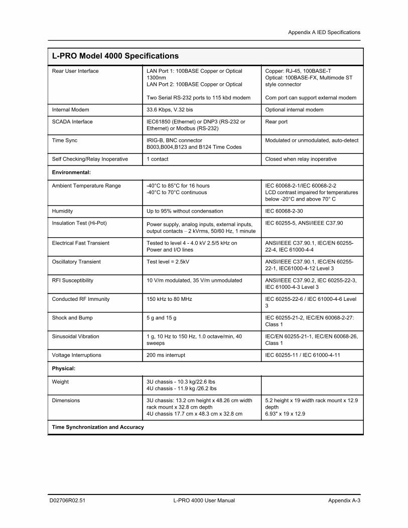
Appendix A IED Specifications
D02706R02.51 L-PRO 4000 User Manual Appendix A-3
Rear User Interface LAN Port 1: 100BASE Copper or Optical 1300nmLAN Port 2: 100BASE Copper or Optical
Two Serial RS-232 ports to 115 kbd modem
Copper: RJ-45, 100BASE-T Optical: 100BASE-FX, Multimode ST style connector
Com port can support external modem
Internal Modem 33.6 Kbps, V.32 bis Optional internal modem
SCADA Interface IEC61850 (Ethernet) or DNP3 (RS-232 or Ethernet) or Modbus (RS-232)
Rear port
Time Sync IRIG-B, BNC connector B003,B004,B123 and B124 Time Codes
Modulated or unmodulated, auto-detect
Self Checking/Relay Inoperative 1 contact Closed when relay inoperative
Environmental:
Ambient Temperature Range -40°C to 85°C for 16 hours-40°C to 70°C continuous
IEC 60068-2-1/IEC 60068-2-2LCD contrast impaired for temperatures below -20°C and above 70° C
Humidity Up to 95% without condensation IEC 60068-2-30
Insulation Test (Hi-Pot) Power supply, analog inputs, external inputs, output contacts – 2 kVrms, 50/60 Hz, 1 minute
IEC 60255-5, ANSI/IEEE C37.90
Electrical Fast Transient Tested to level 4 - 4.0 kV 2.5/5 kHz onPower and I/O lines
ANSI/IEEE C37.90.1, IEC/EN 60255-22-4, IEC 61000-4-4
Oscillatory Transient Test level = 2.5kV ANSI/IEEE C37.90.1, IEC/EN 60255-22-1, IEC61000-4-12 Level 3
RFI Susceptibility 10 V/m modulated, 35 V/m unmodulated ANSI/IEEE C37.90.2, IEC 60255-22-3, IEC 61000-4-3 Level 3
Conducted RF Immunity 150 kHz to 80 MHz IEC 60255-22-6 / IEC 61000-4-6 Level 3
Shock and Bump 5 g and 15 g IEC 60255-21-2, IEC/EN 60068-2-27: Class 1
Sinusoidal Vibration 1 g, 10 Hz to 150 Hz, 1.0 octave/min, 40 sweeps
IEC/EN 60255-21-1, IEC/EN 60068-26, Class 1
Voltage Interruptions 200 ms interrupt IEC 60255-11 / IEC 61000-4-11
Physical:
Weight 3U chassis - 10.3 kg/22.6 lbs4U chassis - 11.9 kg /26.2 lbs
Dimensions 3U chassis: 13.2 cm height x 48.26 cm width rack mount x 32.8 cm depth4U chassis 17.7 cm x 48.3 cm x 32.8 cm
5.2 height x 19 width rack mount x 12.9 depth 6.93" x 19 x 12.9
Time Synchronization and Accuracy
L-PRO Model 4000 Specifications
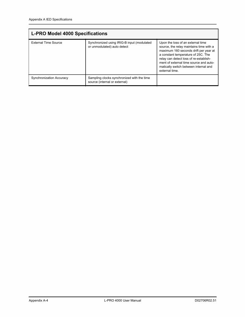
Appendix A IED Specifications
Appendix A-4 L-PRO 4000 User Manual D02706R02.51
External Time Source Synchronized using IRIG-B input (modulated or unmodulated) auto detect
Upon the loss of an external time source, the relay maintains time with a maximum 160 seconds drift per year at a constant temperature of 25C. The relay can detect loss of re-establish-ment of external time source and auto-matically switch between internal and external time.
Synchronization Accuracy Sampling clocks synchronized with the time source (internal or external)
L-PRO Model 4000 Specifications
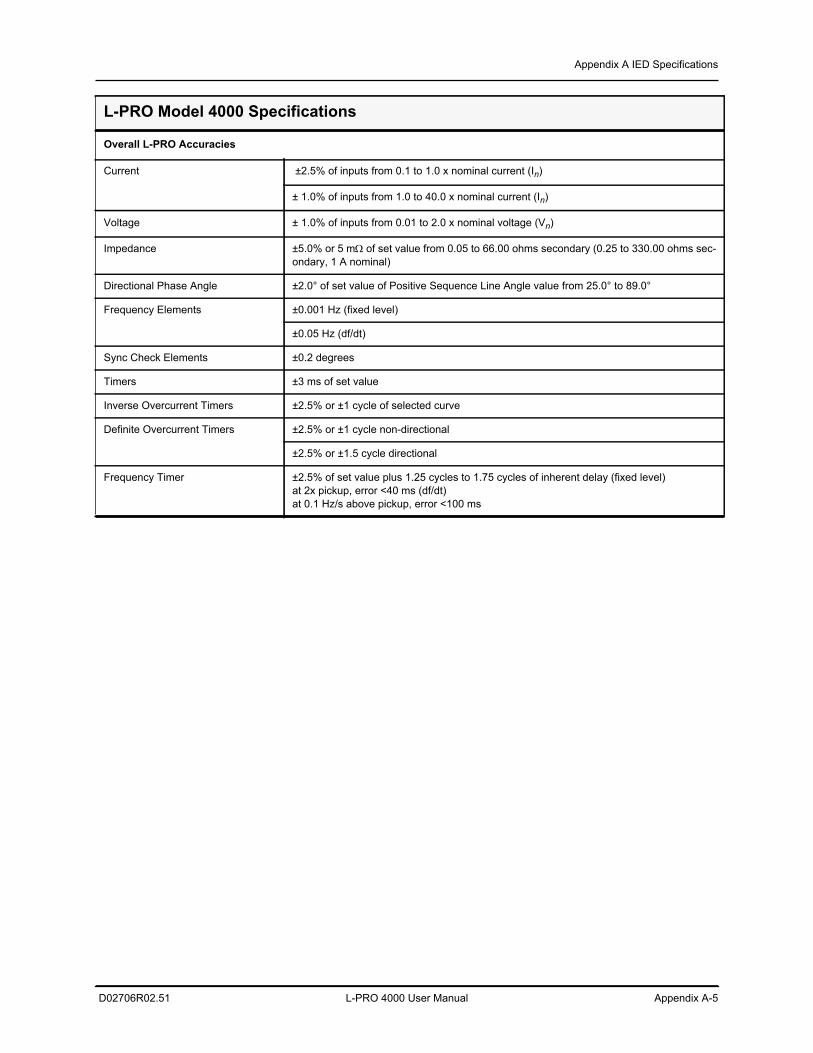
Appendix A IED Specifications
D02706R02.51 L-PRO 4000 User Manual Appendix A-5
Overall L-PRO Accuracies
Current ±2.5% of inputs from 0.1 to 1.0 x nominal current (In)
± 1.0% of inputs from 1.0 to 40.0 x nominal current (In)
Voltage ± 1.0% of inputs from 0.01 to 2.0 x nominal voltage (Vn)
Impedance ±5.0% or 5 m of set value from 0.05 to 66.00 ohms secondary (0.25 to 330.00 ohms sec-ondary, 1 A nominal)
Directional Phase Angle ±2.0° of set value of Positive Sequence Line Angle value from 25.0° to 89.0°
Frequency Elements ±0.001 Hz (fixed level)
±0.05 Hz (df/dt)
Sync Check Elements ±0.2 degrees
Timers ±3 ms of set value
Inverse Overcurrent Timers ±2.5% or ±1 cycle of selected curve
Definite Overcurrent Timers ±2.5% or ±1 cycle non-directional
±2.5% or ±1.5 cycle directional
Frequency Timer ±2.5% of set value plus 1.25 cycles to 1.75 cycles of inherent delay (fixed level)at 2x pickup, error <40 ms (df/dt)at 0.1 Hz/s above pickup, error <100 ms
L-PRO Model 4000 Specifications
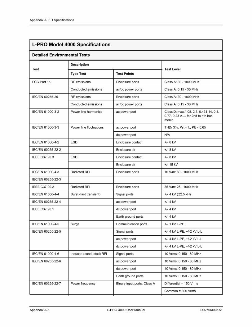
Appendix A IED Specifications
Appendix A-6 L-PRO 4000 User Manual D02706R02.51
L-PRO Model 4000 Specifications
Detailed Environmental Tests
TestDescription
Test LevelType Test Test Points
FCC Part 15 RF emissions Enclosure ports Class A: 30 - 1000 MHz
Conducted emissions ac/dc power ports Class A: 0.15 - 30 MHz
IEC/EN 60255-25 RF emissions Enclosure ports Class A: 30 - 1000 MHz
Conducted emissions ac/dc power ports Class A: 0.15 - 30 MHz
IEC/EN 61000-3-2 Power line harmonics ac power port Class D: max.1.08, 2.3, 0.431.14, 0.3, 0.77, 0.23 A.... for 2nd to nth har-monic
IEC/EN 61000-3-3 Power line fluctuations ac power port THD/ 3%; Pst <1., Plt < 0.65
dc power port N/A
IEC/EN 61000-4-2 ESD Enclosure contact +/- 6 kV
IEC/EN 60255-22-2 Enclosure air +/- 8 kV
IEEE C37.90.3 ESD Enclosure contact +/- 8 kV
Enclosure air +/- 15 kV
IEC/EN 61000-4-3 Radiated RFI Enclosure ports 10 V/m: 80 - 1000 MHz
IEC/EN 60255-22-3
IEEE C37.90.2 Radiated RFI Enclosure ports 35 V/m: 25 - 1000 MHz
IEC/EN 61000-4-4 Burst (fast transient) Signal ports +/- 4 kV @2.5 kHz
IEC/EN 60255-22-4 ac power port +/- 4 kV
IEEE C37.90.1 dc power port +/- 4 kV
Earth ground ports +/- 4 kV
IEC/EN 61000-4-5 Surge Communication ports +/- 1 kV L-PE
IEC/EN 60255-22-5 Signal ports +/- 4 kV L-PE, +/-2 kV L-L
ac power port +/- 4 kV L-PE, +/-2 kV L-L
dc power port +/- 4 kV L-PE, +/-2 kV L-L
IEC/EN 61000-4-6 Induced (conducted) RFI Signal ports 10 Vrms: 0.150 - 80 MHz
IEC/EN 60255-22-6 ac power port 10 Vrms: 0.150 - 80 MHz
dc power port 10 Vrms: 0.150 - 80 MHz
Earth ground ports 10 Vrms: 0.150 - 80 MHz
IEC/EN 60255-22-7 Power frequency Binary input ports: Class A Differential = 150 Vrms
Common = 300 Vrms
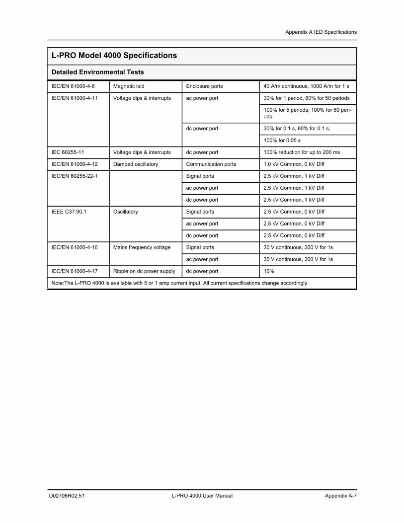
Appendix A IED Specifications
D02706R02.51 L-PRO 4000 User Manual Appendix A-7
IEC/EN 61000-4-8 Magnetic leld Enclosure ports 40 A/m continuous, 1000 A/m for 1 s
IEC/EN 61000-4-11 Voltage dips & interrupts ac power port 30% for 1 period, 60% for 50 periods
100% for 5 periods, 100% for 50 peri-ods
dc power port 30% for 0.1 s, 60% for 0.1 s,
100% for 0.05 s
IEC 60255-11 Voltage dips & interrupts dc power port 100% reduction for up to 200 ms
IEC/EN 61000-4-12 Damped oscillatory Communication ports 1.0 kV Common, 0 kV Diff
IEC/EN 60255-22-1 Signal ports 2.5 kV Common, 1 kV Diff
ac power port 2.5 kV Common, 1 kV Diff
dc power port 2.5 kV Common, 1 kV Diff
IEEE C37.90.1 Oscillatory Signal ports 2.5 kV Common, 0 kV Diff
ac power port 2.5 kV Common, 0 kV Diff
dc power port 2.5 kV Common, 0 kV Diff
IEC/EN 61000-4-16 Mains frequency voltage Signal ports 30 V continuous, 300 V for 1s
ac power port 30 V continuous, 300 V for 1s
IEC/EN 61000-4-17 Ripple on dc power supply dc power port 10%
Note:The L-PRO 4000 is available with 5 or 1 amp current input. All current specifications change accordingly.
L-PRO Model 4000 Specifications
Detailed Environmental Tests
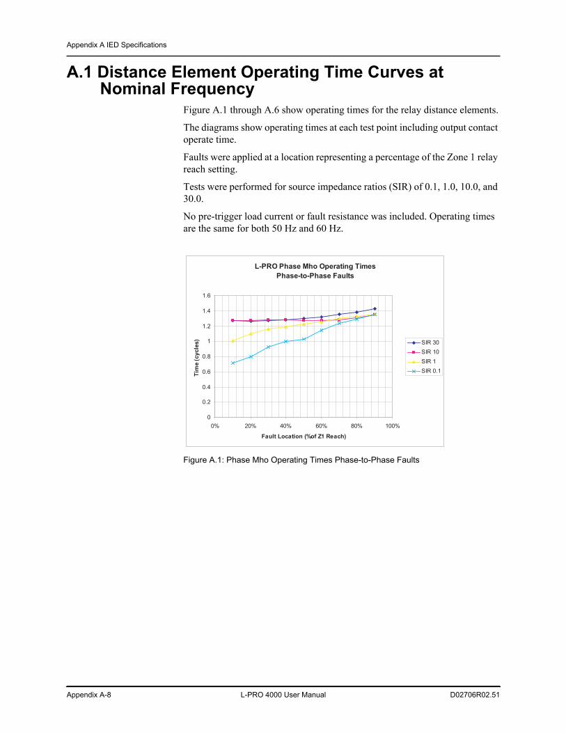
Appendix A IED Specifications
Appendix A-8 L-PRO 4000 User Manual D02706R02.51
A.1 Distance Element Operating Time Curves at Nominal Frequency
Figure A.1 through A.6 show operating times for the relay distance elements.
The diagrams show operating times at each test point including output contact operate time.
Faults were applied at a location representing a percentage of the Zone 1 relay reach setting.
Tests were performed for source impedance ratios (SIR) of 0.1, 1.0, 10.0, and 30.0.
No pre-trigger load current or fault resistance was included. Operating times are the same for both 50 Hz and 60 Hz.
Figure A.1: Phase Mho Operating Times Phase-to-Phase Faults
L-PRO Phase Mho Operating TimesPhase-to-Phase Faults
0
0.2
0.4
0.6
0.8
1
1.2
1.4
1.6
0% 20% 40% 60% 80% 100%
Fault Location (%of Z1 Reach)
Tim
e (c
ycle
s) SIR 30SIR 10SIR 1SIR 0.1
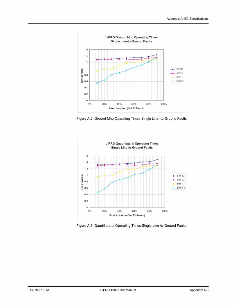
Appendix A IED Specifications
D02706R02.51 L-PRO 4000 User Manual Appendix A-9
Figure A.2: Ground Mho Operating Times Single Line -to-Ground Faults
Figure A.3: Quadrilateral Operating Times Single Line-to-Ground Faults
L-PRO Ground Mho Operating TimesSingle Line-to-Ground Faults
0
0.2
0.4
0.6
0.8
1
1.2
1.4
1.6
0% 20% 40% 60% 80% 100%
Fault Location (%of Z1 Reach)
Tim
e (c
ycle
s) SIR 30SIR 10SIR 1SIR 0.1
L-PRO Quadrilateral Operating TimesSingle Line-to-Ground Faults
0
0.2
0.4
0.6
0.8
1
1.2
1.4
1.6
0% 20% 40% 60% 80% 100%
Fault Location (%of Z1 Reach)
Tim
e (c
ycle
s) SIR 30SIR 10SIR 1SIR 0.1
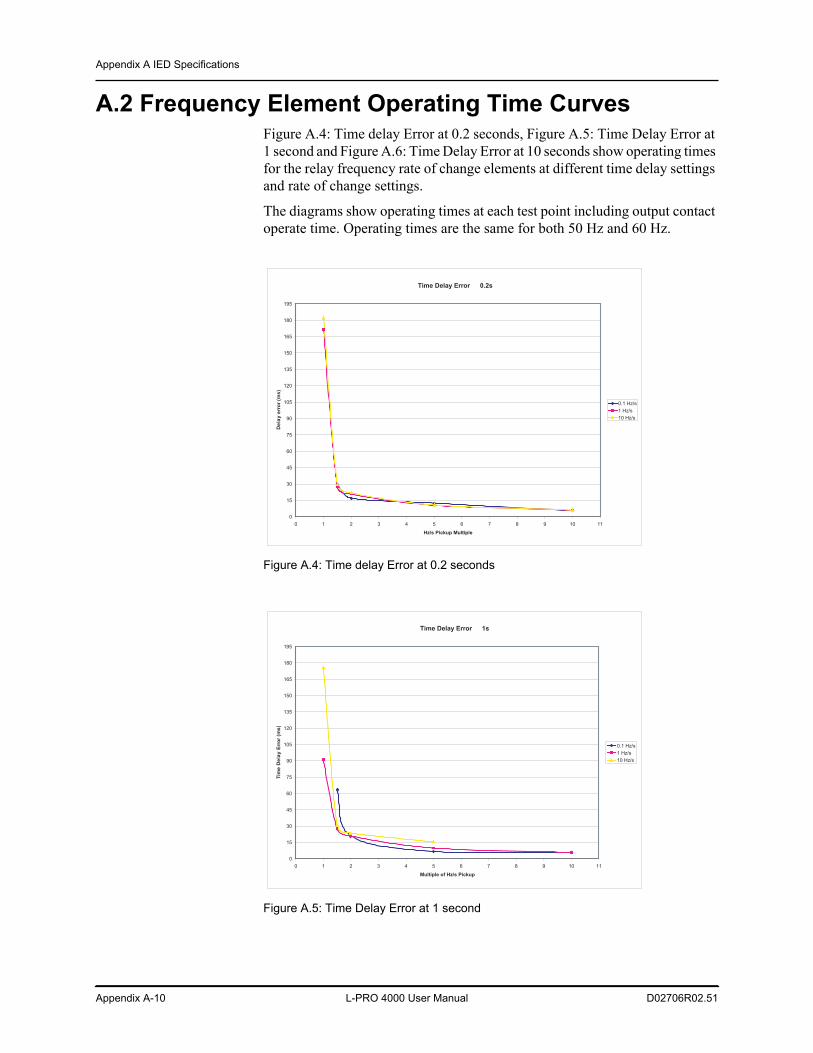
Appendix A IED Specifications
Appendix A-10 L-PRO 4000 User Manual D02706R02.51
A.2 Frequency Element Operating Time CurvesFigure A.4: Time delay Error at 0.2 seconds, Figure A.5: Time Delay Error at 1 second and Figure A.6: Time Delay Error at 10 seconds show operating times for the relay frequency rate of change elements at different time delay settings and rate of change settings.
The diagrams show operating times at each test point including output contact operate time. Operating times are the same for both 50 Hz and 60 Hz.
Figure A.4: Time delay Error at 0.2 seconds
Figure A.5: Time Delay Error at 1 second
Time Delay Error � 0.2s
0
15
30
45
60
75
90
105
120
135
150
165
180
195
0 1 2 3 4 5 6 7 8 9 10 11
Hz/s Pickup Multiple
Del
ay e
rror
(ms)
0.1 Hz/s1 Hz/s10 Hz/s
Time Delay Error � 1s
0
15
30
45
60
75
90
105
120
135
150
165
180
195
0 1 2 3 4 5 6 7 8 9 10 11
Multiple of Hz/s Pickup
Tim
e D
elay
Err
or (m
s)
0.1 Hz/s1 Hz/s10 Hz/s
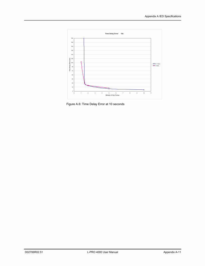
Appendix A IED Specifications
D02706R02.51 L-PRO 4000 User Manual Appendix A-11
Figure A.6: Time Delay Error at 10 seconds
Time Delay Error � 10s
0
15
30
45
60
75
90
105
120
135
150
165
180
195
0 1 2 3 4 5 6 7 8 9 10 11
Multiple of Hz/s Pickup
Tim
e D
elay
Err
or (m
s)
0.1 Hz/s1 Hz/s
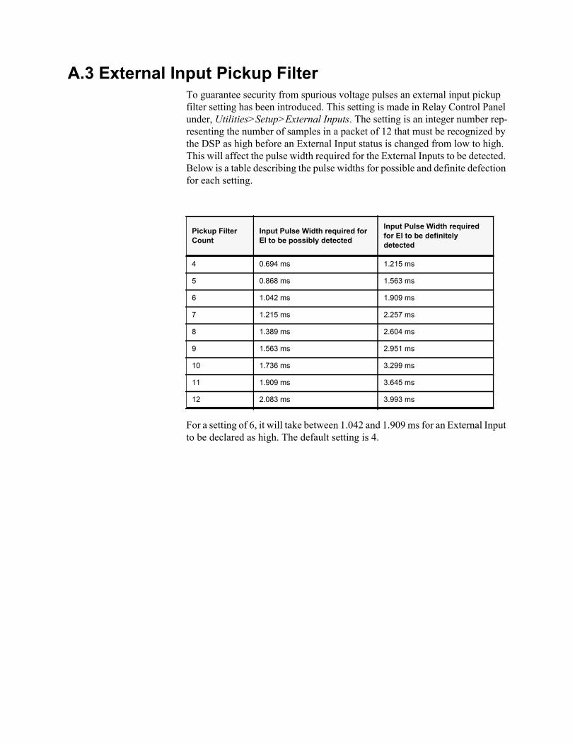
A.3 External Input Pickup Filter To guarantee security from spurious voltage pulses an external input pickup filter setting has been introduced. This setting is made in Relay Control Panel under, Utilities>Setup>External Inputs. The setting is an integer number rep-resenting the number of samples in a packet of 12 that must be recognized by the DSP as high before an External Input status is changed from low to high. This will affect the pulse width required for the External Inputs to be detected. Below is a table describing the pulse widths for possible and definite defection for each setting.
For a setting of 6, it will take between 1.042 and 1.909 ms for an External Input to be declared as high. The default setting is 4.
Pickup Filter Count
Input Pulse Width required for EI to be possibly detected
Input Pulse Width required for EI to be definitely detected
4 0.694 ms 1.215 ms
5 0.868 ms 1.563 ms
6 1.042 ms 1.909 ms
7 1.215 ms 2.257 ms
8 1.389 ms 2.604 ms
9 1.563 ms 2.951 ms
10 1.736 ms 3.299 ms
11 1.909 ms 3.645 ms
12 2.083 ms 3.993 ms
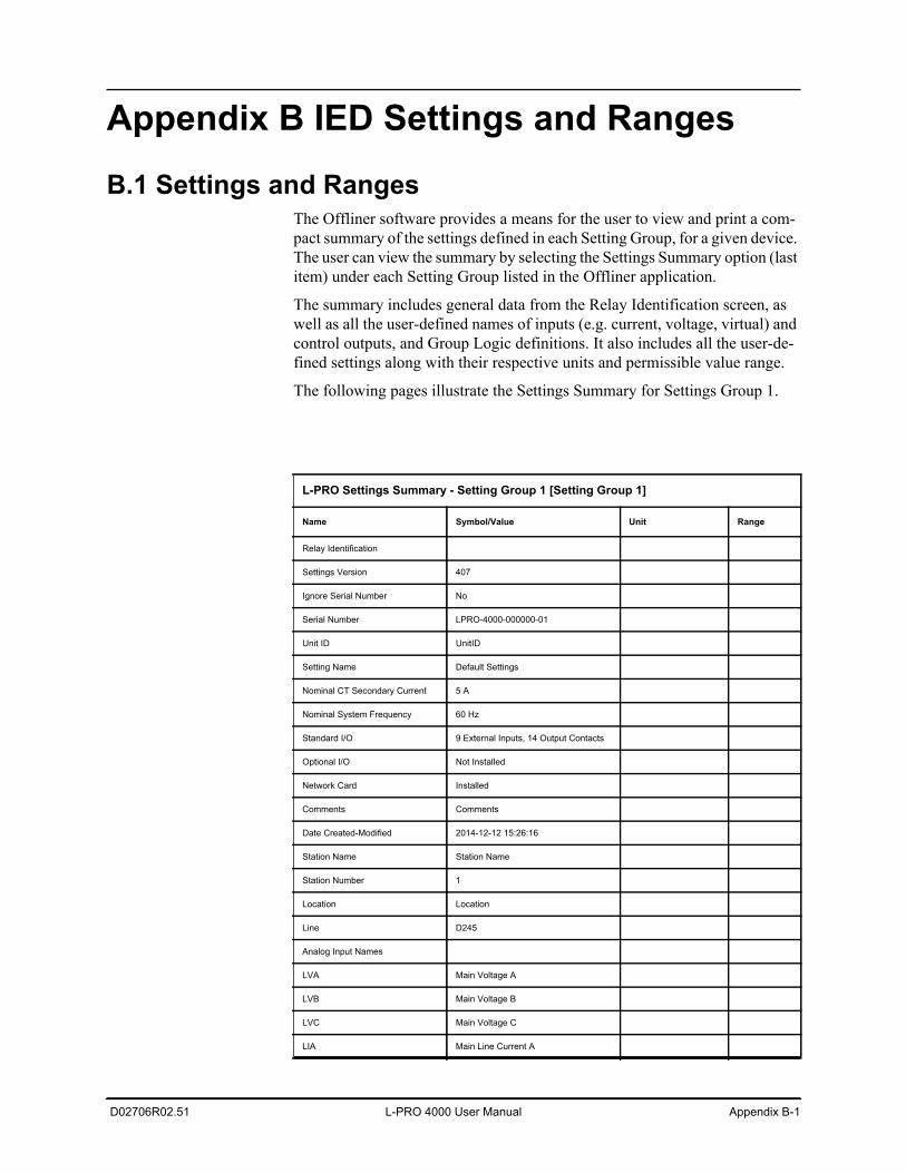
D02706R02.51 L-PRO 4000 User Manual Appendix B-1
Appendix B IED Settings and Ranges
B.1 Settings and RangesThe Offliner software provides a means for the user to view and print a com-pact summary of the settings defined in each Setting Group, for a given device. The user can view the summary by selecting the Settings Summary option (last item) under each Setting Group listed in the Offliner application.
The summary includes general data from the Relay Identification screen, as well as all the user-defined names of inputs (e.g. current, voltage, virtual) and control outputs, and Group Logic definitions. It also includes all the user-de-fined settings along with their respective units and permissible value range.
The following pages illustrate the Settings Summary for Settings Group 1.
L-PRO Settings Summary - Setting Group 1 [Setting Group 1]
Name Symbol/Value Unit Range
Relay Identification
Settings Version 407
Ignore Serial Number No
Serial Number LPRO-4000-000000-01
Unit ID UnitID
Setting Name Default Settings
Nominal CT Secondary Current 5 A
Nominal System Frequency 60 Hz
Standard I/O 9 External Inputs, 14 Output Contacts
Optional I/O Not Installed
Network Card Installed
Comments Comments
Date Created-Modified 2014-12-12 15:26:16
Station Name Station Name
Station Number 1
Location Location
Line D245
Analog Input Names
LVA Main Voltage A
LVB Main Voltage B
LVC Main Voltage C
LIA Main Line Current A
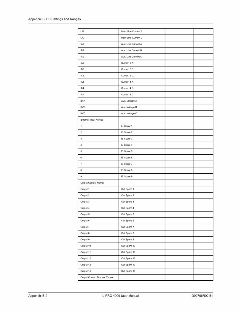
Appendix B IED Settings and Ranges
Appendix B-2 L-PRO 4000 User Manual D02706R02.51
LIB Main Line Current B
LIC Main Line Current C
IA2 Aux. Line Current A
IB2 Aux. Line Current B
IC2 Aux. Line Current C
IA3 Current 3 A
IB3 Current 3 B
IC3 Current 3 C
IA4 Current 4 A
IB4 Current 4 B
IC4 Current 4 C
BVA Aux. Voltage A
BVB Aux. Voltage B
BVC Aux. Voltage C
External Input Names
1 EI Spare 1
2 EI Spare 2
3 EI Spare 3
4 EI Spare 4
5 EI Spare 5
6 EI Spare 6
7 EI Spare 7
8 EI Spare 8
9 EI Spare 9
Output Contact Names
Output 1 Out Spare 1
Output 2 Out Spare 2
Output 3 Out Spare 3
Output 4 Out Spare 4
Output 5 Out Spare 5
Output 6 Out Spare 6
Output 7 Out Spare 7
Output 8 Out Spare 8
Output 9 Out Spare 9
Output 10 Out Spare 10
Output 11 Out Spare 11
Output 12 Out Spare 12
Output 13 Out Spare 13
Output 14 Out Spare 14
Output Contact Dropout Timers
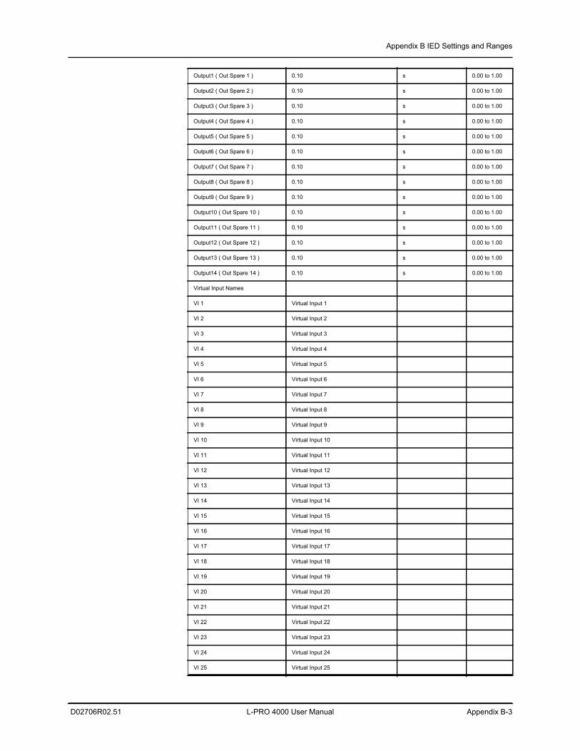
Appendix B IED Settings and Ranges
D02706R02.51 L-PRO 4000 User Manual Appendix B-3
Output1 ( Out Spare 1 ) 0.10 s 0.00 to 1.00
Output2 ( Out Spare 2 ) 0.10 s 0.00 to 1.00
Output3 ( Out Spare 3 ) 0.10 s 0.00 to 1.00
Output4 ( Out Spare 4 ) 0.10 s 0.00 to 1.00
Output5 ( Out Spare 5 ) 0.10 s 0.00 to 1.00
Output6 ( Out Spare 6 ) 0.10 s 0.00 to 1.00
Output7 ( Out Spare 7 ) 0.10 s 0.00 to 1.00
Output8 ( Out Spare 8 ) 0.10 s 0.00 to 1.00
Output9 ( Out Spare 9 ) 0.10 s 0.00 to 1.00
Output10 ( Out Spare 10 ) 0.10 s 0.00 to 1.00
Output11 ( Out Spare 11 ) 0.10 s 0.00 to 1.00
Output12 ( Out Spare 12 ) 0.10 s 0.00 to 1.00
Output13 ( Out Spare 13 ) 0.10 s 0.00 to 1.00
Output14 ( Out Spare 14 ) 0.10 s 0.00 to 1.00
Virtual Input Names
VI 1 Virtual Input 1
VI 2 Virtual Input 2
VI 3 Virtual Input 3
VI 4 Virtual Input 4
VI 5 Virtual Input 5
VI 6 Virtual Input 6
VI 7 Virtual Input 7
VI 8 Virtual Input 8
VI 9 Virtual Input 9
VI 10 Virtual Input 10
VI 11 Virtual Input 11
VI 12 Virtual Input 12
VI 13 Virtual Input 13
VI 14 Virtual Input 14
VI 15 Virtual Input 15
VI 16 Virtual Input 16
VI 17 Virtual Input 17
VI 18 Virtual Input 18
VI 19 Virtual Input 19
VI 20 Virtual Input 20
VI 21 Virtual Input 21
VI 22 Virtual Input 22
VI 23 Virtual Input 23
VI 24 Virtual Input 24
VI 25 Virtual Input 25
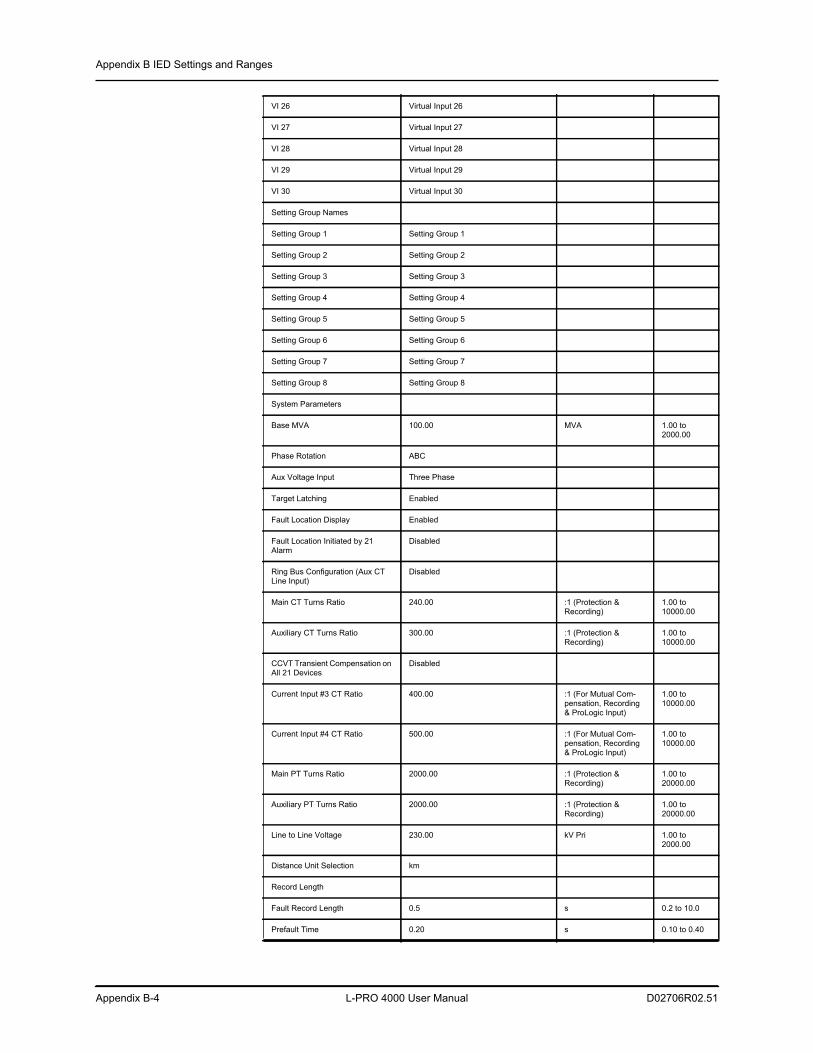
Appendix B IED Settings and Ranges
Appendix B-4 L-PRO 4000 User Manual D02706R02.51
VI 26 Virtual Input 26
VI 27 Virtual Input 27
VI 28 Virtual Input 28
VI 29 Virtual Input 29
VI 30 Virtual Input 30
Setting Group Names
Setting Group 1 Setting Group 1
Setting Group 2 Setting Group 2
Setting Group 3 Setting Group 3
Setting Group 4 Setting Group 4
Setting Group 5 Setting Group 5
Setting Group 6 Setting Group 6
Setting Group 7 Setting Group 7
Setting Group 8 Setting Group 8
System Parameters
Base MVA 100.00 MVA 1.00 to 2000.00
Phase Rotation ABC
Aux Voltage Input Three Phase
Target Latching Enabled
Fault Location Display Enabled
Fault Location Initiated by 21 Alarm
Disabled
Ring Bus Configuration (Aux CT Line Input)
Disabled
Main CT Turns Ratio 240.00 :1 (Protection & Recording)
1.00 to 10000.00
Auxiliary CT Turns Ratio 300.00 :1 (Protection & Recording)
1.00 to 10000.00
CCVT Transient Compensation on All 21 Devices
Disabled
Current Input #3 CT Ratio 400.00 :1 (For Mutual Com-pensation, Recording & ProLogic Input)
1.00 to 10000.00
Current Input #4 CT Ratio 500.00 :1 (For Mutual Com-pensation, Recording & ProLogic Input)
1.00 to 10000.00
Main PT Turns Ratio 2000.00 :1 (Protection & Recording)
1.00 to 20000.00
Auxiliary PT Turns Ratio 2000.00 :1 (Protection & Recording)
1.00 to 20000.00
Line to Line Voltage 230.00 kV Pri 1.00 to 2000.00
Distance Unit Selection km
Record Length
Fault Record Length 0.5 s 0.2 to 10.0
Prefault Time 0.20 s 0.10 to 0.40
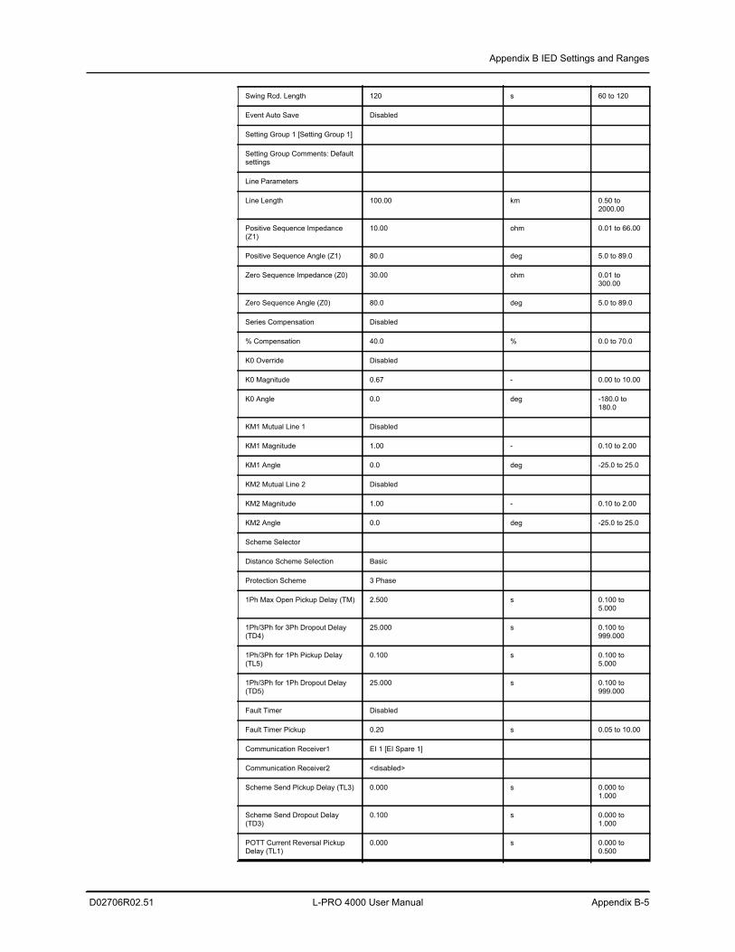
Appendix B IED Settings and Ranges
D02706R02.51 L-PRO 4000 User Manual Appendix B-5
Swing Rcd. Length 120 s 60 to 120
Event Auto Save Disabled
Setting Group 1 [Setting Group 1]
Setting Group Comments: Default settings
Line Parameters
Line Length 100.00 km 0.50 to 2000.00
Positive Sequence Impedance (Z1)
10.00 ohm 0.01 to 66.00
Positive Sequence Angle (Z1) 80.0 deg 5.0 to 89.0
Zero Sequence Impedance (Z0) 30.00 ohm 0.01 to 300.00
Zero Sequence Angle (Z0) 80.0 deg 5.0 to 89.0
Series Compensation Disabled
% Compensation 40.0 % 0.0 to 70.0
K0 Override Disabled
K0 Magnitude 0.67 - 0.00 to 10.00
K0 Angle 0.0 deg -180.0 to 180.0
KM1 Mutual Line 1 Disabled
KM1 Magnitude 1.00 - 0.10 to 2.00
KM1 Angle 0.0 deg -25.0 to 25.0
KM2 Mutual Line 2 Disabled
KM2 Magnitude 1.00 - 0.10 to 2.00
KM2 Angle 0.0 deg -25.0 to 25.0
Scheme Selector
Distance Scheme Selection Basic
Protection Scheme 3 Phase
1Ph Max Open Pickup Delay (TM) 2.500 s 0.100 to 5.000
1Ph/3Ph for 3Ph Dropout Delay (TD4)
25.000 s 0.100 to 999.000
1Ph/3Ph for 1Ph Pickup Delay (TL5)
0.100 s 0.100 to 5.000
1Ph/3Ph for 1Ph Dropout Delay (TD5)
25.000 s 0.100 to 999.000
Fault Timer Disabled
Fault Timer Pickup 0.20 s 0.05 to 10.00
Communication Receiver1 EI 1 [EI Spare 1]
Communication Receiver2 <disabled>
Scheme Send Pickup Delay (TL3) 0.000 s 0.000 to 1.000
Scheme Send Dropout Delay (TD3)
0.100 s 0.000 to 1.000
POTT Current Reversal Pickup Delay (TL1)
0.000 s 0.000 to 0.500
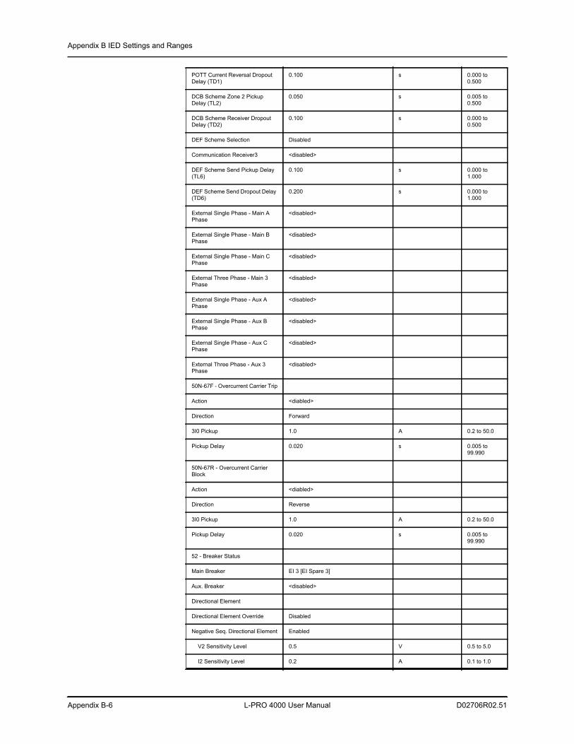
Appendix B IED Settings and Ranges
Appendix B-6 L-PRO 4000 User Manual D02706R02.51
POTT Current Reversal Dropout Delay (TD1)
0.100 s 0.000 to 0.500
DCB Scheme Zone 2 Pickup Delay (TL2)
0.050 s 0.005 to 0.500
DCB Scheme Receiver Dropout Delay (TD2)
0.100 s 0.000 to 0.500
DEF Scheme Selection Disabled
Communication Receiver3 <disabled>
DEF Scheme Send Pickup Delay (TL6)
0.100 s 0.000 to 1.000
DEF Scheme Send Dropout Delay (TD6)
0.200 s 0.000 to 1.000
External Single Phase - Main A Phase
<disabled>
External Single Phase - Main B Phase
<disabled>
External Single Phase - Main C Phase
<disabled>
External Three Phase - Main 3 Phase
<disabled>
External Single Phase - Aux A Phase
<disabled>
External Single Phase - Aux B Phase
<disabled>
External Single Phase - Aux C Phase
<disabled>
External Three Phase - Aux 3 Phase
<disabled>
50N-67F - Overcurrent Carrier Trip
Action <diabled>
Direction Forward
3I0 Pickup 1.0 A 0.2 to 50.0
Pickup Delay 0.020 s 0.005 to 99.990
50N-67R - Overcurrent Carrier Block
Action <diabled>
Direction Reverse
3I0 Pickup 1.0 A 0.2 to 50.0
Pickup Delay 0.020 s 0.005 to 99.990
52 - Breaker Status
Main Breaker EI 3 [EI Spare 3]
Aux. Breaker <disabled>
Directional Element
Directional Element Override Disabled
Negative Seq. Directional Element Enabled
V2 Sensitivity Level 0.5 V 0.5 to 5.0
I2 Sensitivity Level 0.2 A 0.1 to 1.0
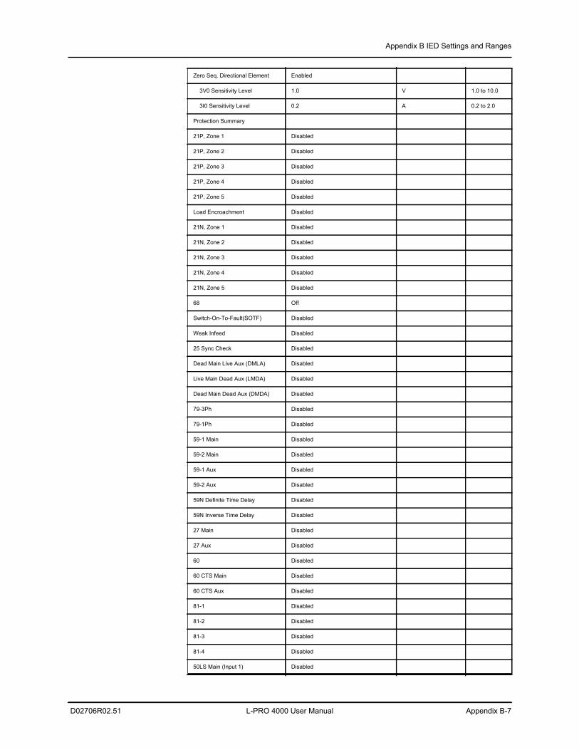
Appendix B IED Settings and Ranges
D02706R02.51 L-PRO 4000 User Manual Appendix B-7
Zero Seq. Directional Element Enabled
3V0 Sensitivity Level 1.0 V 1.0 to 10.0
3I0 Sensitivity Level 0.2 A 0.2 to 2.0
Protection Summary
21P, Zone 1 Disabled
21P, Zone 2 Disabled
21P, Zone 3 Disabled
21P, Zone 4 Disabled
21P, Zone 5 Disabled
Load Encroachment Disabled
21N, Zone 1 Disabled
21N, Zone 2 Disabled
21N, Zone 3 Disabled
21N, Zone 4 Disabled
21N, Zone 5 Disabled
68 Off
Switch-On-To-Fault(SOTF) Disabled
Weak Infeed Disabled
25 Sync Check Disabled
Dead Main Live Aux (DMLA) Disabled
Live Main Dead Aux (LMDA) Disabled
Dead Main Dead Aux (DMDA) Disabled
79-3Ph Disabled
79-1Ph Disabled
59-1 Main Disabled
59-2 Main Disabled
59-1 Aux Disabled
59-2 Aux Disabled
59N Definite Time Delay Disabled
59N Inverse Time Delay Disabled
27 Main Disabled
27 Aux Disabled
60 Disabled
60 CTS Main Disabled
60 CTS Aux Disabled
81-1 Disabled
81-2 Disabled
81-3 Disabled
81-4 Disabled
50LS Main (Input 1) Disabled
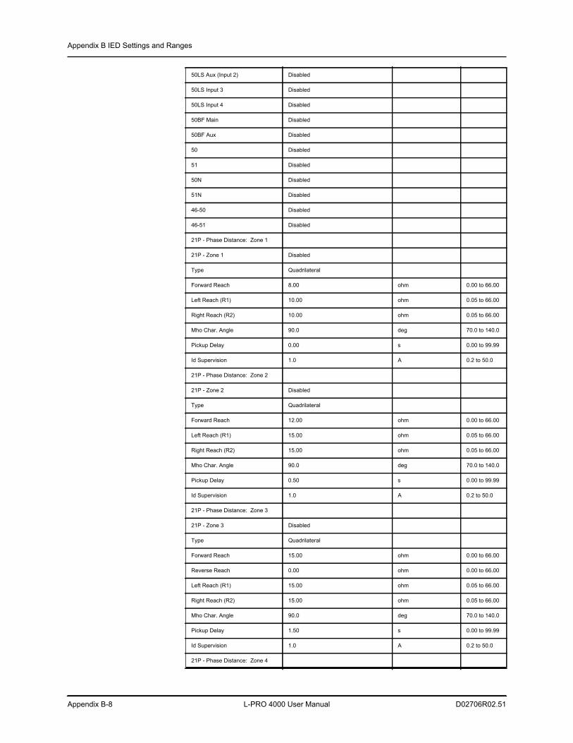
Appendix B IED Settings and Ranges
Appendix B-8 L-PRO 4000 User Manual D02706R02.51
50LS Aux (Input 2) Disabled
50LS Input 3 Disabled
50LS Input 4 Disabled
50BF Main Disabled
50BF Aux Disabled
50 Disabled
51 Disabled
50N Disabled
51N Disabled
46-50 Disabled
46-51 Disabled
21P - Phase Distance: Zone 1
21P - Zone 1 Disabled
Type Quadrilateral
Forward Reach 8.00 ohm 0.00 to 66.00
Left Reach (R1) 10.00 ohm 0.05 to 66.00
Right Reach (R2) 10.00 ohm 0.05 to 66.00
Mho Char. Angle 90.0 deg 70.0 to 140.0
Pickup Delay 0.00 s 0.00 to 99.99
Id Supervision 1.0 A 0.2 to 50.0
21P - Phase Distance: Zone 2
21P - Zone 2 Disabled
Type Quadrilateral
Forward Reach 12.00 ohm 0.00 to 66.00
Left Reach (R1) 15.00 ohm 0.05 to 66.00
Right Reach (R2) 15.00 ohm 0.05 to 66.00
Mho Char. Angle 90.0 deg 70.0 to 140.0
Pickup Delay 0.50 s 0.00 to 99.99
Id Supervision 1.0 A 0.2 to 50.0
21P - Phase Distance: Zone 3
21P - Zone 3 Disabled
Type Quadrilateral
Forward Reach 15.00 ohm 0.00 to 66.00
Reverse Reach 0.00 ohm 0.00 to 66.00
Left Reach (R1) 15.00 ohm 0.05 to 66.00
Right Reach (R2) 15.00 ohm 0.05 to 66.00
Mho Char. Angle 90.0 deg 70.0 to 140.0
Pickup Delay 1.50 s 0.00 to 99.99
Id Supervision 1.0 A 0.2 to 50.0
21P - Phase Distance: Zone 4
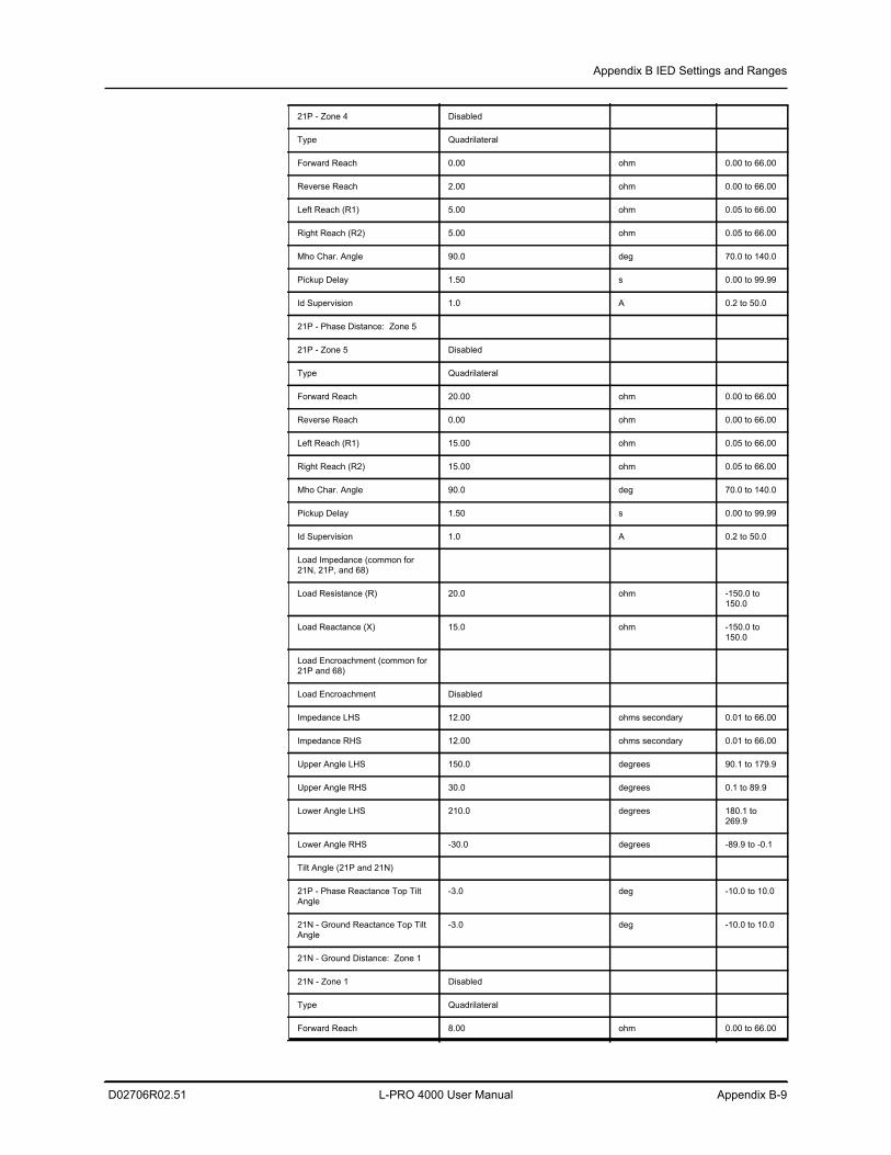
Appendix B IED Settings and Ranges
D02706R02.51 L-PRO 4000 User Manual Appendix B-9
21P - Zone 4 Disabled
Type Quadrilateral
Forward Reach 0.00 ohm 0.00 to 66.00
Reverse Reach 2.00 ohm 0.00 to 66.00
Left Reach (R1) 5.00 ohm 0.05 to 66.00
Right Reach (R2) 5.00 ohm 0.05 to 66.00
Mho Char. Angle 90.0 deg 70.0 to 140.0
Pickup Delay 1.50 s 0.00 to 99.99
Id Supervision 1.0 A 0.2 to 50.0
21P - Phase Distance: Zone 5
21P - Zone 5 Disabled
Type Quadrilateral
Forward Reach 20.00 ohm 0.00 to 66.00
Reverse Reach 0.00 ohm 0.00 to 66.00
Left Reach (R1) 15.00 ohm 0.05 to 66.00
Right Reach (R2) 15.00 ohm 0.05 to 66.00
Mho Char. Angle 90.0 deg 70.0 to 140.0
Pickup Delay 1.50 s 0.00 to 99.99
Id Supervision 1.0 A 0.2 to 50.0
Load Impedance (common for 21N, 21P, and 68)
Load Resistance (R) 20.0 ohm -150.0 to 150.0
Load Reactance (X) 15.0 ohm -150.0 to 150.0
Load Encroachment (common for 21P and 68)
Load Encroachment Disabled
Impedance LHS 12.00 ohms secondary 0.01 to 66.00
Impedance RHS 12.00 ohms secondary 0.01 to 66.00
Upper Angle LHS 150.0 degrees 90.1 to 179.9
Upper Angle RHS 30.0 degrees 0.1 to 89.9
Lower Angle LHS 210.0 degrees 180.1 to 269.9
Lower Angle RHS -30.0 degrees -89.9 to -0.1
Tilt Angle (21P and 21N)
21P - Phase Reactance Top Tilt Angle
-3.0 deg -10.0 to 10.0
21N - Ground Reactance Top Tilt Angle
-3.0 deg -10.0 to 10.0
21N - Ground Distance: Zone 1
21N - Zone 1 Disabled
Type Quadrilateral
Forward Reach 8.00 ohm 0.00 to 66.00
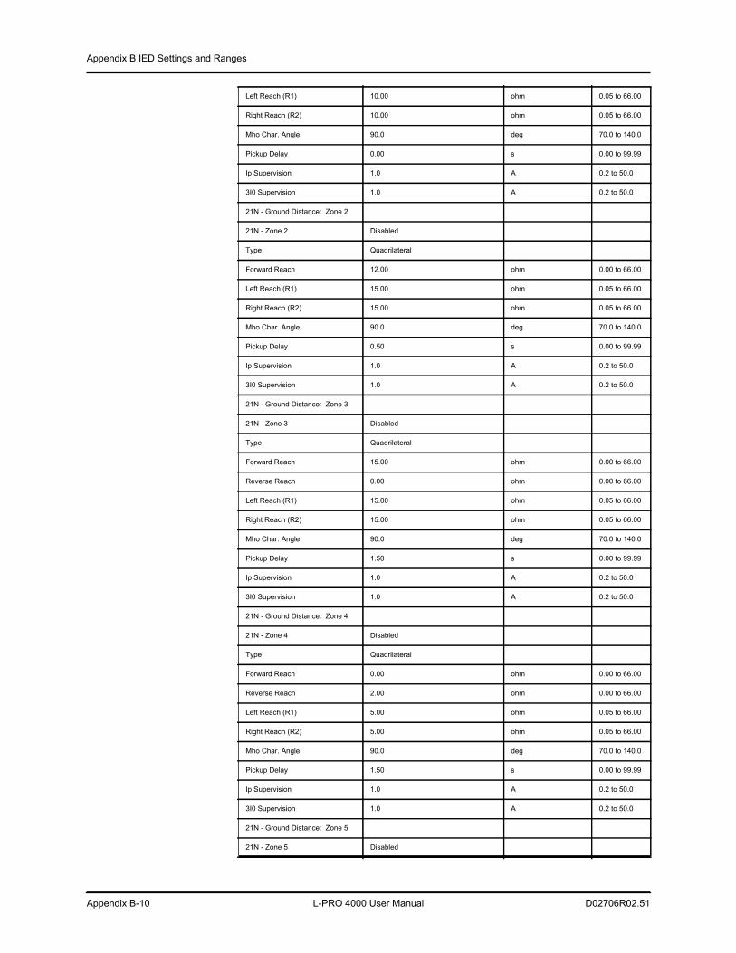
Appendix B IED Settings and Ranges
Appendix B-10 L-PRO 4000 User Manual D02706R02.51
Left Reach (R1) 10.00 ohm 0.05 to 66.00
Right Reach (R2) 10.00 ohm 0.05 to 66.00
Mho Char. Angle 90.0 deg 70.0 to 140.0
Pickup Delay 0.00 s 0.00 to 99.99
Ip Supervision 1.0 A 0.2 to 50.0
3I0 Supervision 1.0 A 0.2 to 50.0
21N - Ground Distance: Zone 2
21N - Zone 2 Disabled
Type Quadrilateral
Forward Reach 12.00 ohm 0.00 to 66.00
Left Reach (R1) 15.00 ohm 0.05 to 66.00
Right Reach (R2) 15.00 ohm 0.05 to 66.00
Mho Char. Angle 90.0 deg 70.0 to 140.0
Pickup Delay 0.50 s 0.00 to 99.99
Ip Supervision 1.0 A 0.2 to 50.0
3I0 Supervision 1.0 A 0.2 to 50.0
21N - Ground Distance: Zone 3
21N - Zone 3 Disabled
Type Quadrilateral
Forward Reach 15.00 ohm 0.00 to 66.00
Reverse Reach 0.00 ohm 0.00 to 66.00
Left Reach (R1) 15.00 ohm 0.05 to 66.00
Right Reach (R2) 15.00 ohm 0.05 to 66.00
Mho Char. Angle 90.0 deg 70.0 to 140.0
Pickup Delay 1.50 s 0.00 to 99.99
Ip Supervision 1.0 A 0.2 to 50.0
3I0 Supervision 1.0 A 0.2 to 50.0
21N - Ground Distance: Zone 4
21N - Zone 4 Disabled
Type Quadrilateral
Forward Reach 0.00 ohm 0.00 to 66.00
Reverse Reach 2.00 ohm 0.00 to 66.00
Left Reach (R1) 5.00 ohm 0.05 to 66.00
Right Reach (R2) 5.00 ohm 0.05 to 66.00
Mho Char. Angle 90.0 deg 70.0 to 140.0
Pickup Delay 1.50 s 0.00 to 99.99
Ip Supervision 1.0 A 0.2 to 50.0
3I0 Supervision 1.0 A 0.2 to 50.0
21N - Ground Distance: Zone 5
21N - Zone 5 Disabled
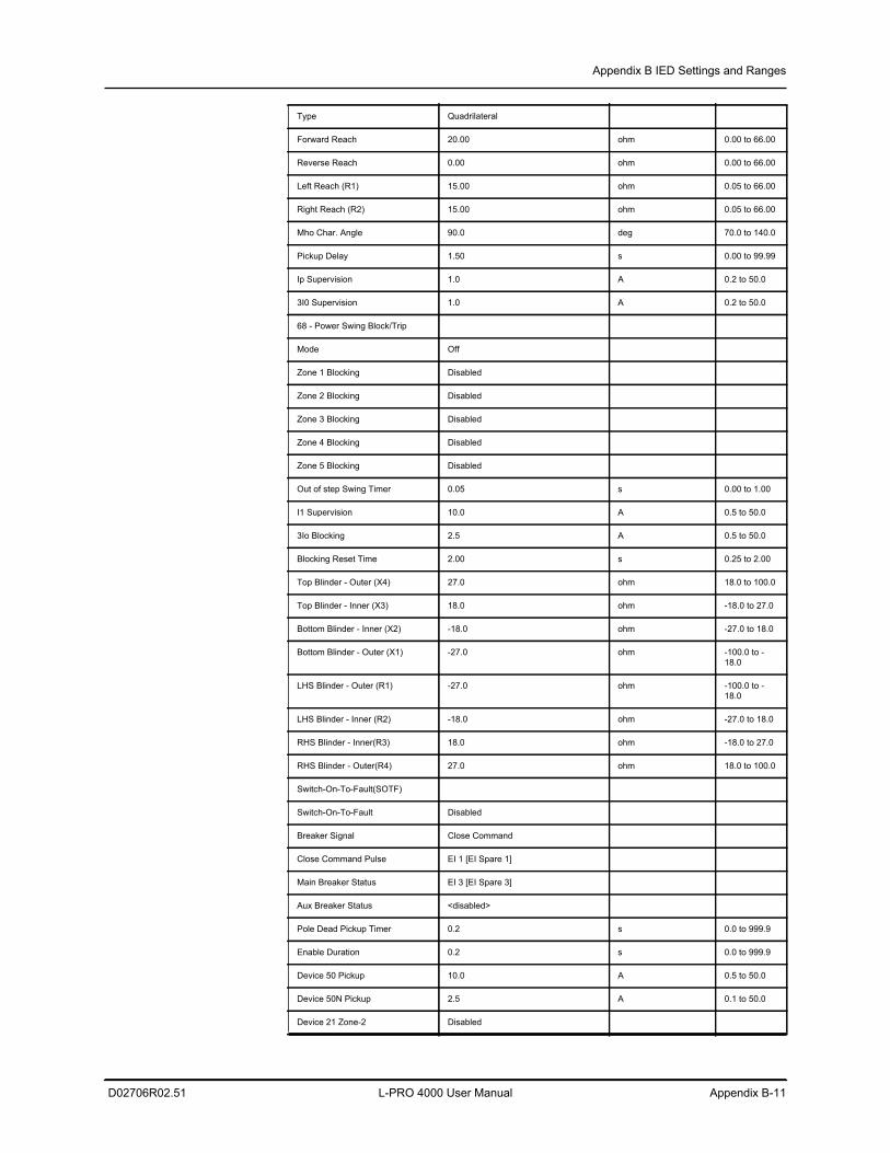
Appendix B IED Settings and Ranges
D02706R02.51 L-PRO 4000 User Manual Appendix B-11
Type Quadrilateral
Forward Reach 20.00 ohm 0.00 to 66.00
Reverse Reach 0.00 ohm 0.00 to 66.00
Left Reach (R1) 15.00 ohm 0.05 to 66.00
Right Reach (R2) 15.00 ohm 0.05 to 66.00
Mho Char. Angle 90.0 deg 70.0 to 140.0
Pickup Delay 1.50 s 0.00 to 99.99
Ip Supervision 1.0 A 0.2 to 50.0
3I0 Supervision 1.0 A 0.2 to 50.0
68 - Power Swing Block/Trip
Mode Off
Zone 1 Blocking Disabled
Zone 2 Blocking Disabled
Zone 3 Blocking Disabled
Zone 4 Blocking Disabled
Zone 5 Blocking Disabled
Out of step Swing Timer 0.05 s 0.00 to 1.00
I1 Supervision 10.0 A 0.5 to 50.0
3Io Blocking 2.5 A 0.5 to 50.0
Blocking Reset Time 2.00 s 0.25 to 2.00
Top Blinder - Outer (X4) 27.0 ohm 18.0 to 100.0
Top Blinder - Inner (X3) 18.0 ohm -18.0 to 27.0
Bottom Blinder - Inner (X2) -18.0 ohm -27.0 to 18.0
Bottom Blinder - Outer (X1) -27.0 ohm -100.0 to -18.0
LHS Blinder - Outer (R1) -27.0 ohm -100.0 to -18.0
LHS Blinder - Inner (R2) -18.0 ohm -27.0 to 18.0
RHS Blinder - Inner(R3) 18.0 ohm -18.0 to 27.0
RHS Blinder - Outer(R4) 27.0 ohm 18.0 to 100.0
Switch-On-To-Fault(SOTF)
Switch-On-To-Fault Disabled
Breaker Signal Close Command
Close Command Pulse EI 1 [EI Spare 1]
Main Breaker Status EI 3 [EI Spare 3]
Aux Breaker Status <disabled>
Pole Dead Pickup Timer 0.2 s 0.0 to 999.9
Enable Duration 0.2 s 0.0 to 999.9
Device 50 Pickup 10.0 A 0.5 to 50.0
Device 50N Pickup 2.5 A 0.1 to 50.0
Device 21 Zone-2 Disabled
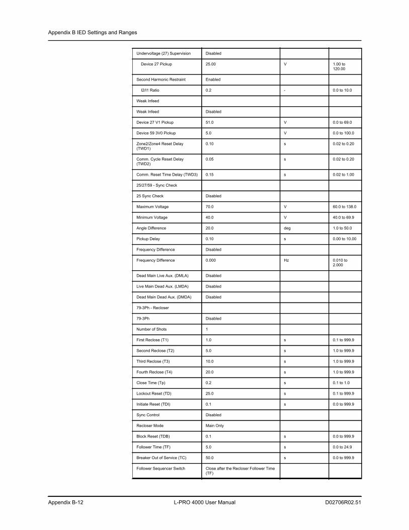
Appendix B IED Settings and Ranges
Appendix B-12 L-PRO 4000 User Manual D02706R02.51
Undervoltage (27) Supervision Disabled
Device 27 Pickup 25.00 V 1.00 to 120.00
Second Harmonic Restraint Enabled
I2/I1 Ratio 0.2 - 0.0 to 10.0
Weak Infeed
Weak Infeed Disabled
Device 27 V1 Pickup 51.0 V 0.0 to 69.0
Device 59 3V0 Pickup 5.0 V 0.0 to 100.0
Zone2/Zone4 Reset Delay (TWD1)
0.10 s 0.02 to 0.20
Comm. Cycle Reset Delay (TWD2)
0.05 s 0.02 to 0.20
Comm. Reset Time Delay (TWD3) 0.15 s 0.02 to 1.00
25/27/59 - Sync Check
25 Sync Check Disabled
Maximum Voltage 70.0 V 60.0 to 138.0
Minimum Voltage 40.0 V 40.0 to 69.9
Angle Difference 20.0 deg 1.0 to 50.0
Pickup Delay 0.10 s 0.00 to 10.00
Frequency Difference Disabled
Frequency Difference 0.000 Hz 0.010 to 2.000
Dead Main Live Aux. (DMLA) Disabled
Live Main Dead Aux. (LMDA) Disabled
Dead Main Dead Aux. (DMDA) Disabled
79-3Ph - Recloser
79-3Ph Disabled
Number of Shots 1
First Reclose (T1) 1.0 s 0.1 to 999.9
Second Reclose (T2) 5.0 s 1.0 to 999.9
Third Reclose (T3) 10.0 s 1.0 to 999.9
Fourth Reclose (T4) 20.0 s 1.0 to 999.9
Close Time (Tp) 0.2 s 0.1 to 1.0
Lockout Reset (TD) 25.0 s 0.1 to 999.9
Initiate Reset (TDI) 0.1 s 0.0 to 999.9
Sync Control Disabled
Recloser Mode Main Only
Block Reset (TDB) 0.1 s 0.0 to 999.9
Follower Time (TF) 5.0 s 0.0 to 24.9
Breaker Out of Service (TC) 50.0 s 0.0 to 999.9
Follower Sequencer Switch Close after the Recloser Follower Time (TF)
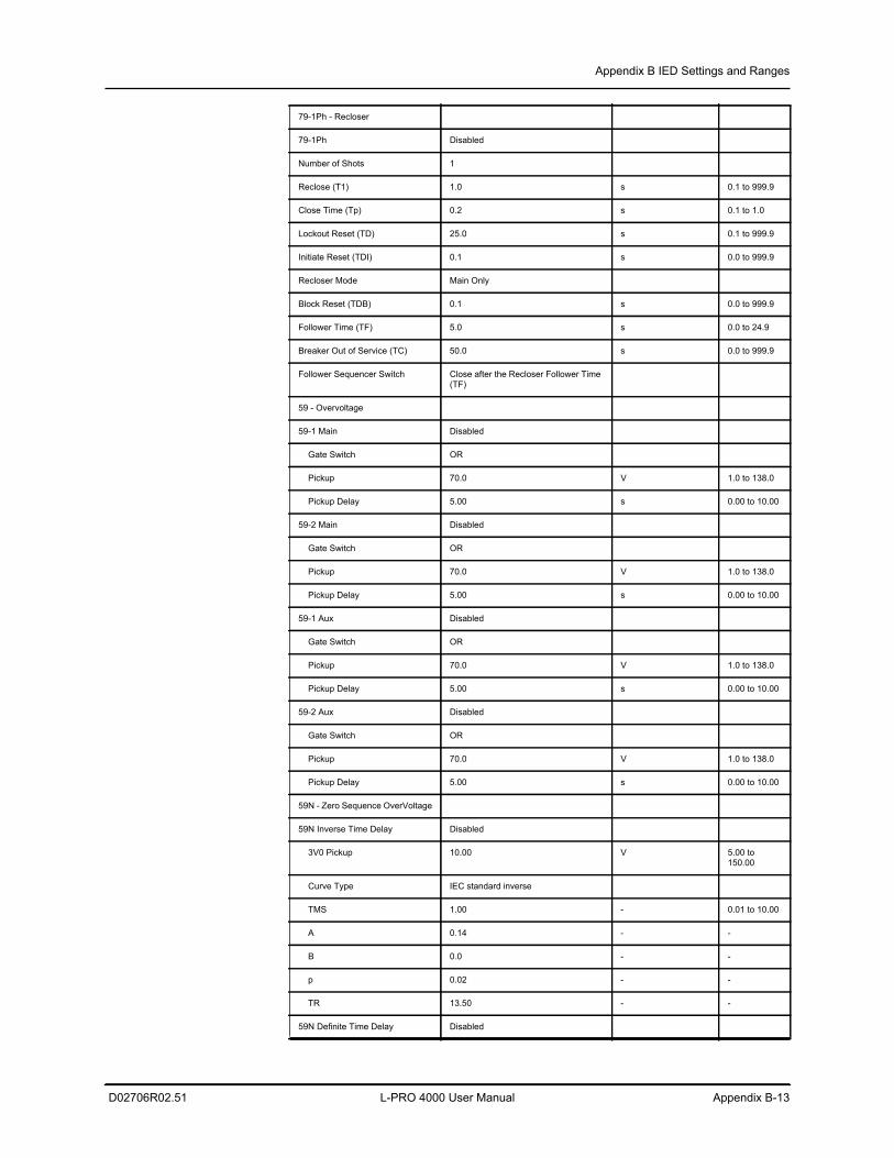
Appendix B IED Settings and Ranges
D02706R02.51 L-PRO 4000 User Manual Appendix B-13
79-1Ph - Recloser
79-1Ph Disabled
Number of Shots 1
Reclose (T1) 1.0 s 0.1 to 999.9
Close Time (Tp) 0.2 s 0.1 to 1.0
Lockout Reset (TD) 25.0 s 0.1 to 999.9
Initiate Reset (TDI) 0.1 s 0.0 to 999.9
Recloser Mode Main Only
Block Reset (TDB) 0.1 s 0.0 to 999.9
Follower Time (TF) 5.0 s 0.0 to 24.9
Breaker Out of Service (TC) 50.0 s 0.0 to 999.9
Follower Sequencer Switch Close after the Recloser Follower Time (TF)
59 - Overvoltage
59-1 Main Disabled
Gate Switch OR
Pickup 70.0 V 1.0 to 138.0
Pickup Delay 5.00 s 0.00 to 10.00
59-2 Main Disabled
Gate Switch OR
Pickup 70.0 V 1.0 to 138.0
Pickup Delay 5.00 s 0.00 to 10.00
59-1 Aux Disabled
Gate Switch OR
Pickup 70.0 V 1.0 to 138.0
Pickup Delay 5.00 s 0.00 to 10.00
59-2 Aux Disabled
Gate Switch OR
Pickup 70.0 V 1.0 to 138.0
Pickup Delay 5.00 s 0.00 to 10.00
59N - Zero Sequence OverVoltage
59N Inverse Time Delay Disabled
3V0 Pickup 10.00 V 5.00 to 150.00
Curve Type IEC standard inverse
TMS 1.00 - 0.01 to 10.00
A 0.14 - -
B 0.0 - -
p 0.02 - -
TR 13.50 - -
59N Definite Time Delay Disabled
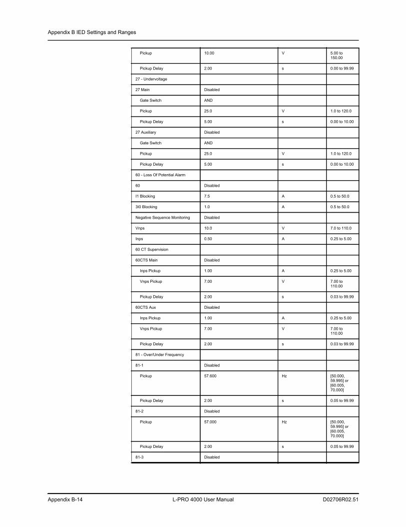
Appendix B IED Settings and Ranges
Appendix B-14 L-PRO 4000 User Manual D02706R02.51
Pickup 10.00 V 5.00 to 150.00
Pickup Delay 2.00 s 0.00 to 99.99
27 - Undervoltage
27 Main Disabled
Gate Switch AND
Pickup 25.0 V 1.0 to 120.0
Pickup Delay 5.00 s 0.00 to 10.00
27 Auxiliary Disabled
Gate Switch AND
Pickup 25.0 V 1.0 to 120.0
Pickup Delay 5.00 s 0.00 to 10.00
60 - Loss Of Potential Alarm
60 Disabled
I1 Blocking 7.5 A 0.5 to 50.0
3I0 Blocking 1.0 A 0.5 to 50.0
Negative Sequence Monitoring Disabled
Vnps 10.0 V 7.0 to 110.0
Inps 0.50 A 0.25 to 5.00
60 CT Supervision
60CTS Main Disabled
Inps Pickup 1.00 A 0.25 to 5.00
Vnps Pickup 7.00 V 7.00 to 110.00
Pickup Delay 2.00 s 0.03 to 99.99
60CTS Aux Disabled
Inps Pickup 1.00 A 0.25 to 5.00
Vnps Pickup 7.00 V 7.00 to 110.00
Pickup Delay 2.00 s 0.03 to 99.99
81 - Over/Under Frequency
81-1 Disabled
Pickup 57.600 Hz [50.000, 59.995] or [60.005, 70.000]
Pickup Delay 2.00 s 0.05 to 99.99
81-2 Disabled
Pickup 57.000 Hz [50.000, 59.995] or [60.005, 70.000]
Pickup Delay 2.00 s 0.05 to 99.99
81-3 Disabled
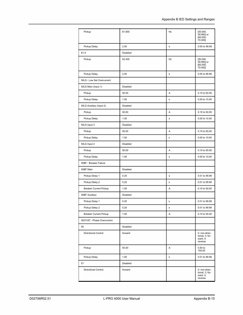
Appendix B IED Settings and Ranges
D02706R02.51 L-PRO 4000 User Manual Appendix B-15
Pickup 61.800 Hz [50.000, 59.995] or [60.005, 70.000]
Pickup Delay 2.00 s 0.05 to 99.99
81-4 Disabled
Pickup 62.400 Hz [50.000, 59.995] or [60.005, 70.000]
Pickup Delay 2.00 s 0.05 to 99.99
50LS - Low Set Overcurrent
50LS Main (Input 1) Disabled
Pickup 50.00 A 0.10 to 50.00
Pickup Delay 1.00 s 0.00 to 10.00
50LS Auxiliary (Input 2) Disabled
Pickup 50.00 A 0.10 to 50.00
Pickup Delay 1.00 s 0.00 to 10.00
50LS Input 3 Disabled
Pickup 50.00 A 0.10 to 50.00
Pickup Delay 1.00 s 0.00 to 10.00
50LS Input 4 Disabled
Pickup 50.00 A 0.10 to 50.00
Pickup Delay 1.00 s 0.00 to 10.00
50BF - Breaker Failure
50BF Main Disabled
Pickup Delay 1 0.20 s 0.01 to 99.99
Pickup Delay 2 0.20 s 0.01 to 99.99
Breaker Current Pickup 1.00 A 0.10 to 50.00
50BF Auxiliary Disabled
Pickup Delay 1 0.20 s 0.01 to 99.99
Pickup Delay 2 0.20 s 0.01 to 99.99
Breaker Current Pickup 1.00 A 0.10 to 50.00
50/51/67 - Phase Overcurrent
50 Disabled
Directional Control forward 0: non-direc-tional, 3: for-ward, 4: reverse
Pickup 50.00 A 0.50 to 150.00
Pickup Delay 1.00 s 0.01 to 99.99
51 Disabled
Directional Control forward 0: non-direc-tional, 3: for-ward, 4: reverse
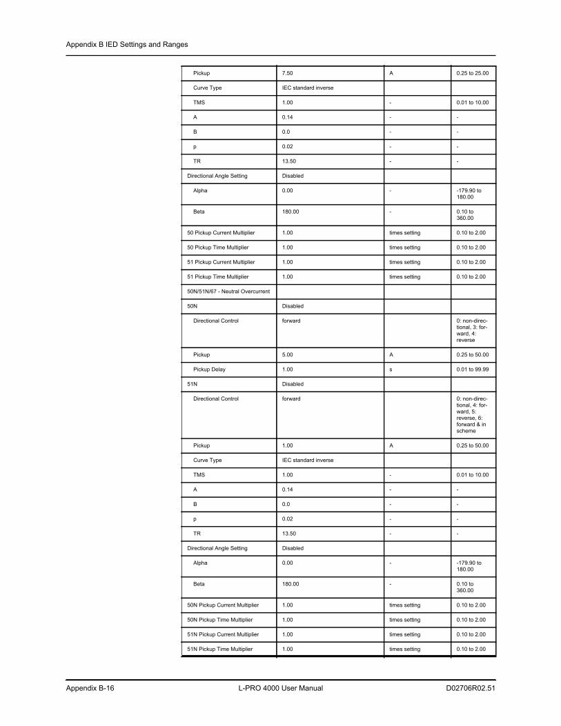
Appendix B IED Settings and Ranges
Appendix B-16 L-PRO 4000 User Manual D02706R02.51
Pickup 7.50 A 0.25 to 25.00
Curve Type IEC standard inverse
TMS 1.00 - 0.01 to 10.00
A 0.14 - -
B 0.0 - -
p 0.02 - -
TR 13.50 - -
Directional Angle Setting Disabled
Alpha 0.00 - -179.90 to 180.00
Beta 180.00 - 0.10 to 360.00
50 Pickup Current Multiplier 1.00 times setting 0.10 to 2.00
50 Pickup Time Multiplier 1.00 times setting 0.10 to 2.00
51 Pickup Current Multiplier 1.00 times setting 0.10 to 2.00
51 Pickup Time Multiplier 1.00 times setting 0.10 to 2.00
50N/51N/67 - Neutral Overcurrent
50N Disabled
Directional Control forward 0: non-direc-tional, 3: for-ward, 4: reverse
Pickup 5.00 A 0.25 to 50.00
Pickup Delay 1.00 s 0.01 to 99.99
51N Disabled
Directional Control forward 0: non-direc-tional, 4: for-ward, 5: reverse, 6: forward & in scheme
Pickup 1.00 A 0.25 to 50.00
Curve Type IEC standard inverse
TMS 1.00 - 0.01 to 10.00
A 0.14 - -
B 0.0 - -
p 0.02 - -
TR 13.50 - -
Directional Angle Setting Disabled
Alpha 0.00 - -179.90 to 180.00
Beta 180.00 - 0.10 to 360.00
50N Pickup Current Multiplier 1.00 times setting 0.10 to 2.00
50N Pickup Time Multiplier 1.00 times setting 0.10 to 2.00
51N Pickup Current Multiplier 1.00 times setting 0.10 to 2.00
51N Pickup Time Multiplier 1.00 times setting 0.10 to 2.00
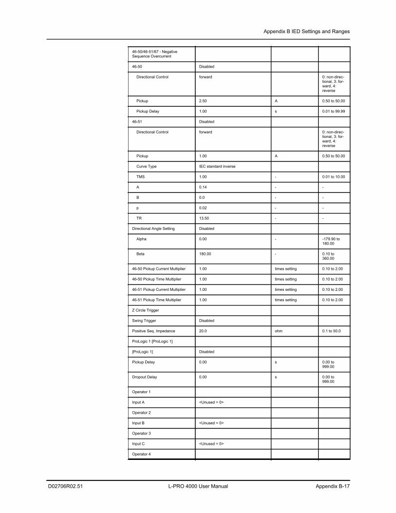
Appendix B IED Settings and Ranges
D02706R02.51 L-PRO 4000 User Manual Appendix B-17
46-50/46-51/67 - Negative Sequence Overcurrent
46-50 Disabled
Directional Control forward 0: non-direc-tional, 3: for-ward, 4: reverse
Pickup 2.50 A 0.50 to 50.00
Pickup Delay 1.00 s 0.01 to 99.99
46-51 Disabled
Directional Control forward 0: non-direc-tional, 3: for-ward, 4: reverse
Pickup 1.00 A 0.50 to 50.00
Curve Type IEC standard inverse
TMS 1.00 - 0.01 to 10.00
A 0.14 - -
B 0.0 - -
p 0.02 - -
TR 13.50 - -
Directional Angle Setting Disabled
Alpha 0.00 - -179.90 to 180.00
Beta 180.00 - 0.10 to 360.00
46-50 Pickup Current Multiplier 1.00 times setting 0.10 to 2.00
46-50 Pickup Time Multiplier 1.00 times setting 0.10 to 2.00
46-51 Pickup Current Multiplier 1.00 times setting 0.10 to 2.00
46-51 Pickup Time Multiplier 1.00 times setting 0.10 to 2.00
Z Circle Trigger
Swing Trigger Disabled
Positive Seq. Impedance 20.0 ohm 0.1 to 50.0
ProLogic 1 [ProLogic 1]
[ProLogic 1] Disabled
Pickup Delay 0.00 s 0.00 to 999.00
Dropout Delay 0.00 s 0.00 to 999.00
Operator 1
Input A <Unused = 0>
Operator 2
Input B <Unused = 0>
Operator 3
Input C <Unused = 0>
Operator 4
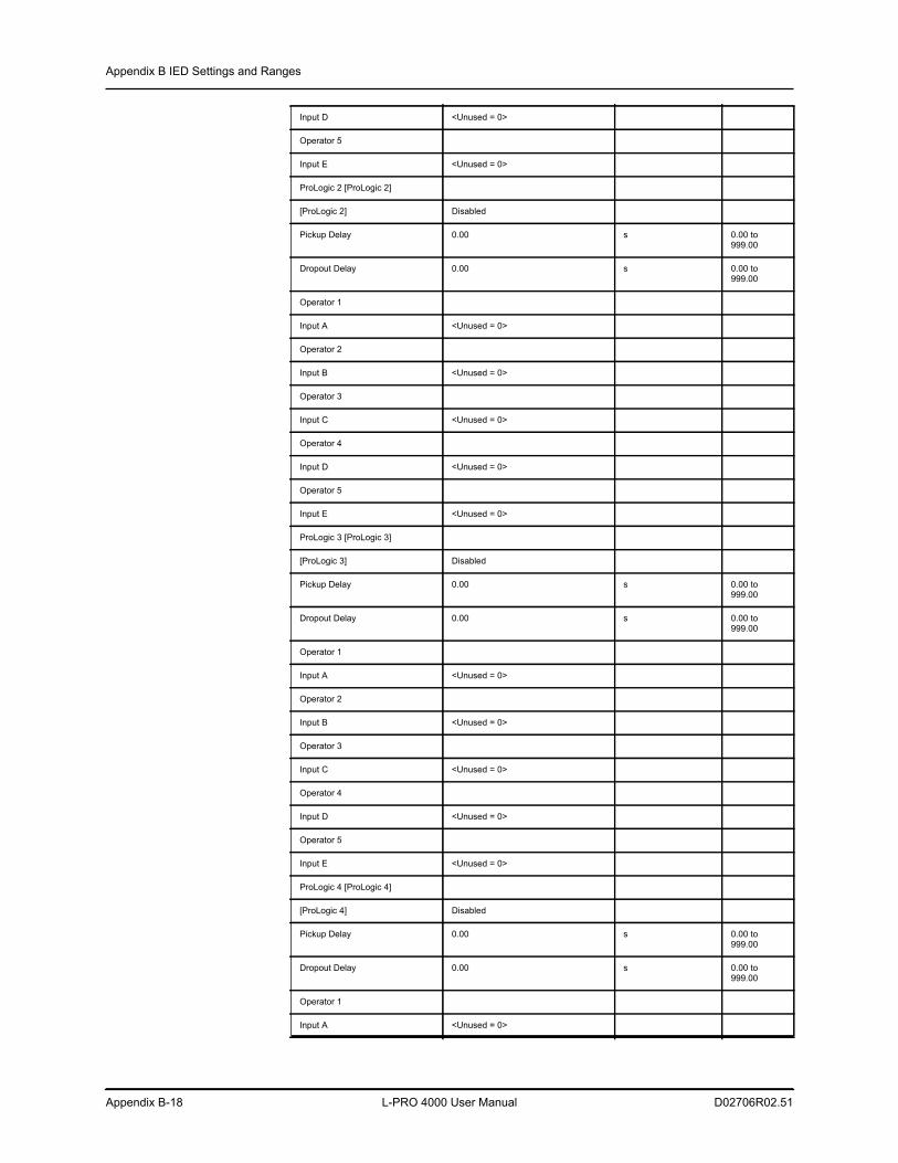
Appendix B IED Settings and Ranges
Appendix B-18 L-PRO 4000 User Manual D02706R02.51
Input D <Unused = 0>
Operator 5
Input E <Unused = 0>
ProLogic 2 [ProLogic 2]
[ProLogic 2] Disabled
Pickup Delay 0.00 s 0.00 to 999.00
Dropout Delay 0.00 s 0.00 to 999.00
Operator 1
Input A <Unused = 0>
Operator 2
Input B <Unused = 0>
Operator 3
Input C <Unused = 0>
Operator 4
Input D <Unused = 0>
Operator 5
Input E <Unused = 0>
ProLogic 3 [ProLogic 3]
[ProLogic 3] Disabled
Pickup Delay 0.00 s 0.00 to 999.00
Dropout Delay 0.00 s 0.00 to 999.00
Operator 1
Input A <Unused = 0>
Operator 2
Input B <Unused = 0>
Operator 3
Input C <Unused = 0>
Operator 4
Input D <Unused = 0>
Operator 5
Input E <Unused = 0>
ProLogic 4 [ProLogic 4]
[ProLogic 4] Disabled
Pickup Delay 0.00 s 0.00 to 999.00
Dropout Delay 0.00 s 0.00 to 999.00
Operator 1
Input A <Unused = 0>

Appendix B IED Settings and Ranges
D02706R02.51 L-PRO 4000 User Manual Appendix B-19
Operator 2
Input B <Unused = 0>
Operator 3
Input C <Unused = 0>
Operator 4
Input D <Unused = 0>
Operator 5
Input E <Unused = 0>
ProLogic 5 [ProLogic 5]
[ProLogic 5] Disabled
Pickup Delay 0.00 s 0.00 to 999.00
Dropout Delay 0.00 s 0.00 to 999.00
Operator 1
Input A <Unused = 0>
Operator 2
Input B <Unused = 0>
Operator 3
Input C <Unused = 0>
Operator 4
Input D <Unused = 0>
Operator 5
Input E <Unused = 0>
ProLogic 6 [ProLogic 6]
[ProLogic 6] Disabled
Pickup Delay 0.00 s 0.00 to 999.00
Dropout Delay 0.00 s 0.00 to 999.00
Operator 1
Input A <Unused = 0>
Operator 2
Input B <Unused = 0>
Operator 3
Input C <Unused = 0>
Operator 4
Input D <Unused = 0>
Operator 5
Input E <Unused = 0>
ProLogic 7 [ProLogic 7]
[ProLogic 7] Disabled
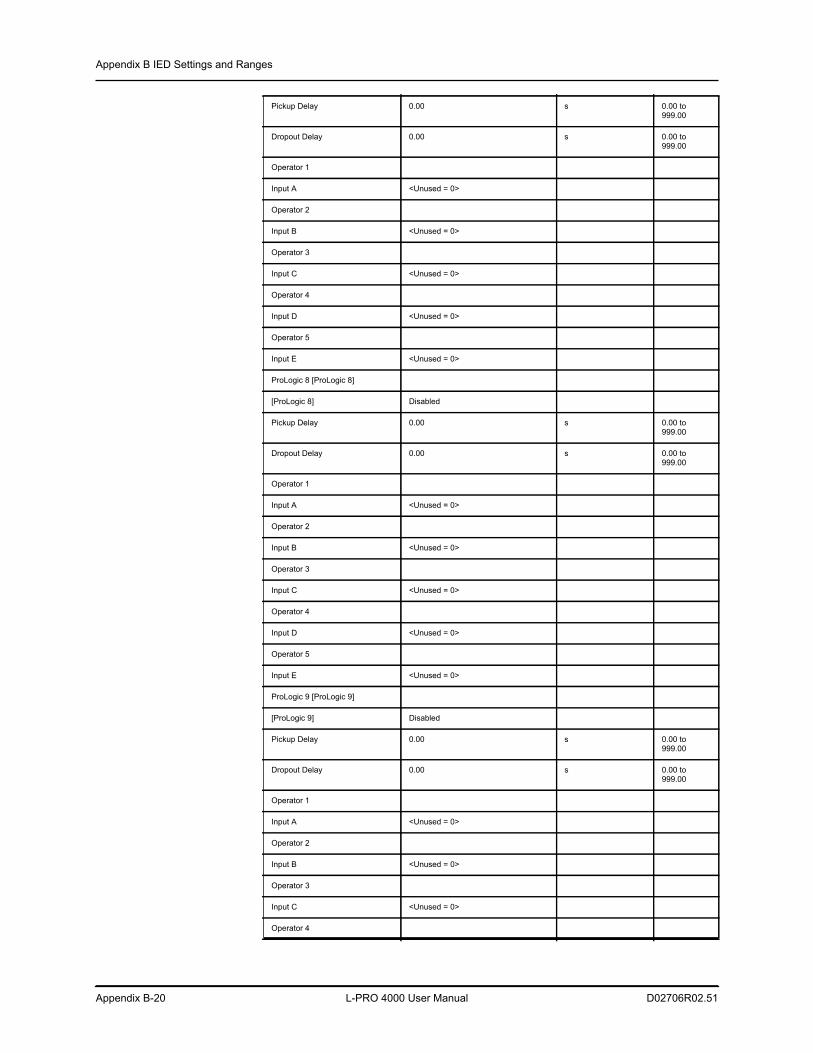
Appendix B IED Settings and Ranges
Appendix B-20 L-PRO 4000 User Manual D02706R02.51
Pickup Delay 0.00 s 0.00 to 999.00
Dropout Delay 0.00 s 0.00 to 999.00
Operator 1
Input A <Unused = 0>
Operator 2
Input B <Unused = 0>
Operator 3
Input C <Unused = 0>
Operator 4
Input D <Unused = 0>
Operator 5
Input E <Unused = 0>
ProLogic 8 [ProLogic 8]
[ProLogic 8] Disabled
Pickup Delay 0.00 s 0.00 to 999.00
Dropout Delay 0.00 s 0.00 to 999.00
Operator 1
Input A <Unused = 0>
Operator 2
Input B <Unused = 0>
Operator 3
Input C <Unused = 0>
Operator 4
Input D <Unused = 0>
Operator 5
Input E <Unused = 0>
ProLogic 9 [ProLogic 9]
[ProLogic 9] Disabled
Pickup Delay 0.00 s 0.00 to 999.00
Dropout Delay 0.00 s 0.00 to 999.00
Operator 1
Input A <Unused = 0>
Operator 2
Input B <Unused = 0>
Operator 3
Input C <Unused = 0>
Operator 4
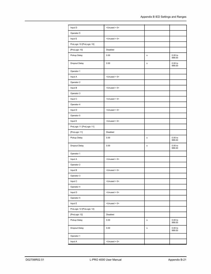
Appendix B IED Settings and Ranges
D02706R02.51 L-PRO 4000 User Manual Appendix B-21
Input D <Unused = 0>
Operator 5
Input E <Unused = 0>
ProLogic 10 [ProLogic 10]
[ProLogic 10] Disabled
Pickup Delay 0.00 s 0.00 to 999.00
Dropout Delay 0.00 s 0.00 to 999.00
Operator 1
Input A <Unused = 0>
Operator 2
Input B <Unused = 0>
Operator 3
Input C <Unused = 0>
Operator 4
Input D <Unused = 0>
Operator 5
Input E <Unused = 0>
ProLogic 11 [ProLogic 11]
[ProLogic 11] Disabled
Pickup Delay 0.00 s 0.00 to 999.00
Dropout Delay 0.00 s 0.00 to 999.00
Operator 1
Input A <Unused = 0>
Operator 2
Input B <Unused = 0>
Operator 3
Input C <Unused = 0>
Operator 4
Input D <Unused = 0>
Operator 5
Input E <Unused = 0>
ProLogic 12 [ProLogic 12]
[ProLogic 12] Disabled
Pickup Delay 0.00 s 0.00 to 999.00
Dropout Delay 0.00 s 0.00 to 999.00
Operator 1
Input A <Unused = 0>
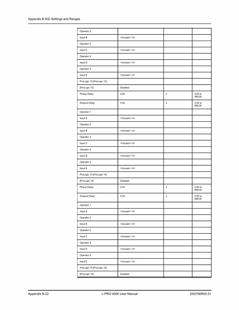
Appendix B IED Settings and Ranges
Appendix B-22 L-PRO 4000 User Manual D02706R02.51
Operator 2
Input B <Unused = 0>
Operator 3
Input C <Unused = 0>
Operator 4
Input D <Unused = 0>
Operator 5
Input E <Unused = 0>
ProLogic 13 [ProLogic 13]
[ProLogic 13] Disabled
Pickup Delay 0.00 s 0.00 to 999.00
Dropout Delay 0.00 s 0.00 to 999.00
Operator 1
Input A <Unused = 0>
Operator 2
Input B <Unused = 0>
Operator 3
Input C <Unused = 0>
Operator 4
Input D <Unused = 0>
Operator 5
Input E <Unused = 0>
ProLogic 14 [ProLogic 14]
[ProLogic 14] Disabled
Pickup Delay 0.00 s 0.00 to 999.00
Dropout Delay 0.00 s 0.00 to 999.00
Operator 1
Input A <Unused = 0>
Operator 2
Input B <Unused = 0>
Operator 3
Input C <Unused = 0>
Operator 4
Input D <Unused = 0>
Operator 5
Input E <Unused = 0>
ProLogic 15 [ProLogic 15]
[ProLogic 15] Disabled
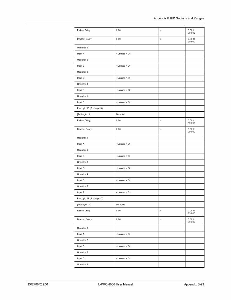
Appendix B IED Settings and Ranges
D02706R02.51 L-PRO 4000 User Manual Appendix B-23
Pickup Delay 0.00 s 0.00 to 999.00
Dropout Delay 0.00 s 0.00 to 999.00
Operator 1
Input A <Unused = 0>
Operator 2
Input B <Unused = 0>
Operator 3
Input C <Unused = 0>
Operator 4
Input D <Unused = 0>
Operator 5
Input E <Unused = 0>
ProLogic 16 [ProLogic 16]
[ProLogic 16] Disabled
Pickup Delay 0.00 s 0.00 to 999.00
Dropout Delay 0.00 s 0.00 to 999.00
Operator 1
Input A <Unused = 0>
Operator 2
Input B <Unused = 0>
Operator 3
Input C <Unused = 0>
Operator 4
Input D <Unused = 0>
Operator 5
Input E <Unused = 0>
ProLogic 17 [ProLogic 17]
[ProLogic 17] Disabled
Pickup Delay 0.00 s 0.00 to 999.00
Dropout Delay 0.00 s 0.00 to 999.00
Operator 1
Input A <Unused = 0>
Operator 2
Input B <Unused = 0>
Operator 3
Input C <Unused = 0>
Operator 4
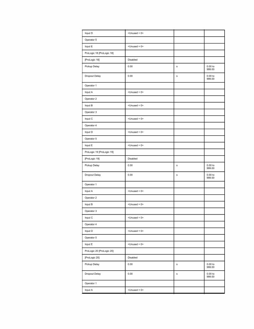
Input D <Unused = 0>
Operator 5
Input E <Unused = 0>
ProLogic 18 [ProLogic 18]
[ProLogic 18] Disabled
Pickup Delay 0.00 s 0.00 to 999.00
Dropout Delay 0.00 s 0.00 to 999.00
Operator 1
Input A <Unused = 0>
Operator 2
Input B <Unused = 0>
Operator 3
Input C <Unused = 0>
Operator 4
Input D <Unused = 0>
Operator 5
Input E <Unused = 0>
ProLogic 19 [ProLogic 19]
[ProLogic 19] Disabled
Pickup Delay 0.00 s 0.00 to 999.00
Dropout Delay 0.00 s 0.00 to 999.00
Operator 1
Input A <Unused = 0>
Operator 2
Input B <Unused = 0>
Operator 3
Input C <Unused = 0>
Operator 4
Input D <Unused = 0>
Operator 5
Input E <Unused = 0>
ProLogic 20 [ProLogic 20]
[ProLogic 20] Disabled
Pickup Delay 0.00 s 0.00 to 999.00
Dropout Delay 0.00 s 0.00 to 999.00
Operator 1
Input A <Unused = 0>
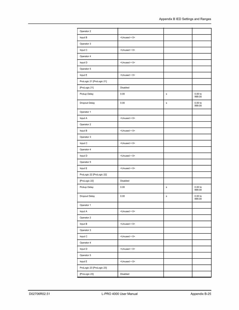
Appendix B IED Settings and Ranges
D02706R02.51 L-PRO 4000 User Manual Appendix B-25
Operator 2
Input B <Unused = 0>
Operator 3
Input C <Unused = 0>
Operator 4
Input D <Unused = 0>
Operator 5
Input E <Unused = 0>
ProLogic 21 [ProLogic 21]
[ProLogic 21] Disabled
Pickup Delay 0.00 s 0.00 to 999.00
Dropout Delay 0.00 s 0.00 to 999.00
Operator 1
Input A <Unused = 0>
Operator 2
Input B <Unused = 0>
Operator 3
Input C <Unused = 0>
Operator 4
Input D <Unused = 0>
Operator 5
Input E <Unused = 0>
ProLogic 22 [ProLogic 22]
[ProLogic 22] Disabled
Pickup Delay 0.00 s 0.00 to 999.00
Dropout Delay 0.00 s 0.00 to 999.00
Operator 1
Input A <Unused = 0>
Operator 2
Input B <Unused = 0>
Operator 3
Input C <Unused = 0>
Operator 4
Input D <Unused = 0>
Operator 5
Input E <Unused = 0>
ProLogic 23 [ProLogic 23]
[ProLogic 23] Disabled
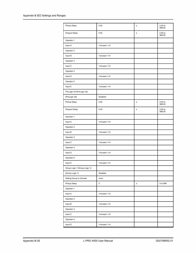
Appendix B IED Settings and Ranges
Appendix B-26 L-PRO 4000 User Manual D02706R02.51
Pickup Delay 0.00 s 0.00 to 999.00
Dropout Delay 0.00 s 0.00 to 999.00
Operator 1
Input A <Unused = 0>
Operator 2
Input B <Unused = 0>
Operator 3
Input C <Unused = 0>
Operator 4
Input D <Unused = 0>
Operator 5
Input E <Unused = 0>
ProLogic 24 [ProLogic 24]
[ProLogic 24] Disabled
Pickup Delay 0.00 s 0.00 to 999.00
Dropout Delay 0.00 s 0.00 to 999.00
Operator 1
Input A <Unused = 0>
Operator 2
Input B <Unused = 0>
Operator 3
Input C <Unused = 0>
Operator 4
Input D <Unused = 0>
Operator 5
Input E <Unused = 0>
Group Logic 1 [Group Logic 1]
[Group Logic 1] Disabled
Setting Group to Activate none
Pickup Delay 0 s 0 to 999
Operator 1
Input A <Unused = 0>
Operator 2
Input B <Unused = 0>
Operator 3
Input C <Unused = 0>
Operator 4
Input D <Unused = 0>
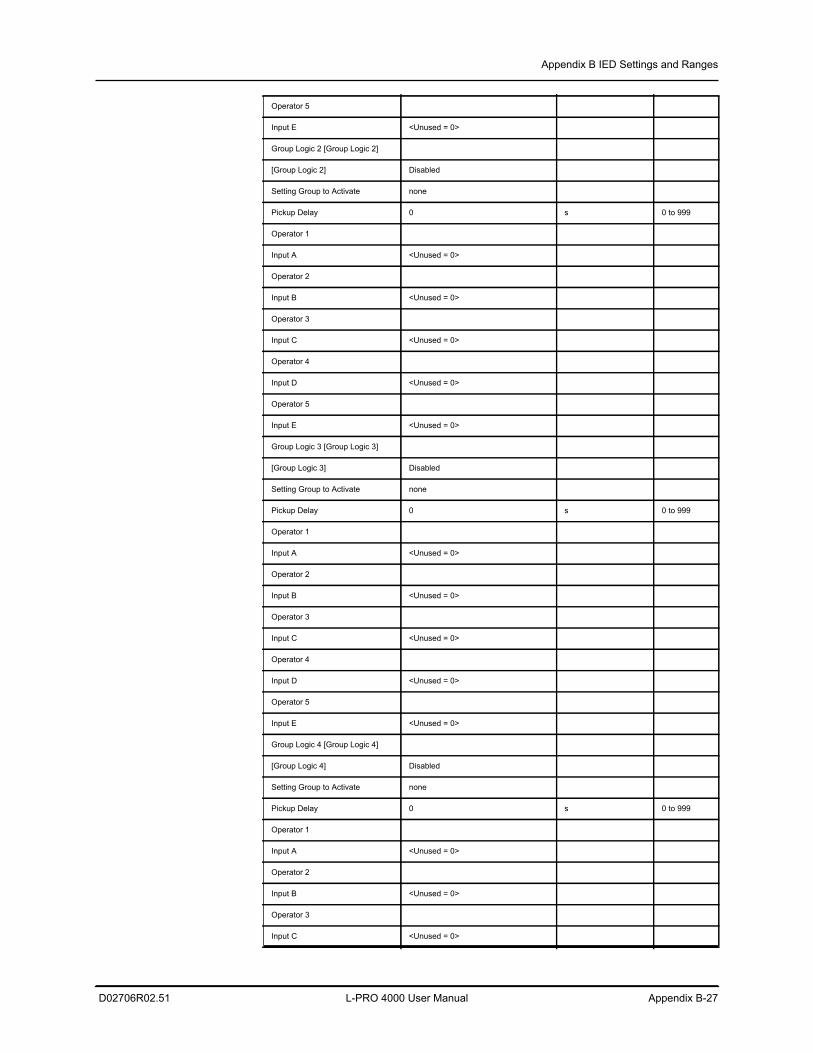
Appendix B IED Settings and Ranges
D02706R02.51 L-PRO 4000 User Manual Appendix B-27
Operator 5
Input E <Unused = 0>
Group Logic 2 [Group Logic 2]
[Group Logic 2] Disabled
Setting Group to Activate none
Pickup Delay 0 s 0 to 999
Operator 1
Input A <Unused = 0>
Operator 2
Input B <Unused = 0>
Operator 3
Input C <Unused = 0>
Operator 4
Input D <Unused = 0>
Operator 5
Input E <Unused = 0>
Group Logic 3 [Group Logic 3]
[Group Logic 3] Disabled
Setting Group to Activate none
Pickup Delay 0 s 0 to 999
Operator 1
Input A <Unused = 0>
Operator 2
Input B <Unused = 0>
Operator 3
Input C <Unused = 0>
Operator 4
Input D <Unused = 0>
Operator 5
Input E <Unused = 0>
Group Logic 4 [Group Logic 4]
[Group Logic 4] Disabled
Setting Group to Activate none
Pickup Delay 0 s 0 to 999
Operator 1
Input A <Unused = 0>
Operator 2
Input B <Unused = 0>
Operator 3
Input C <Unused = 0>
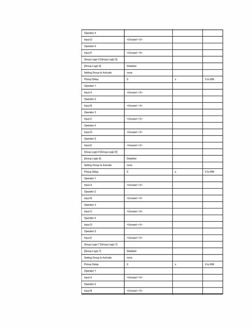
Operator 4
Input D <Unused = 0>
Operator 5
Input E <Unused = 0>
Group Logic 5 [Group Logic 5]
[Group Logic 5] Disabled
Setting Group to Activate none
Pickup Delay 0 s 0 to 999
Operator 1
Input A <Unused = 0>
Operator 2
Input B <Unused = 0>
Operator 3
Input C <Unused = 0>
Operator 4
Input D <Unused = 0>
Operator 5
Input E <Unused = 0>
Group Logic 6 [Group Logic 6]
[Group Logic 6] Disabled
Setting Group to Activate none
Pickup Delay 0 s 0 to 999
Operator 1
Input A <Unused = 0>
Operator 2
Input B <Unused = 0>
Operator 3
Input C <Unused = 0>
Operator 4
Input D <Unused = 0>
Operator 5
Input E <Unused = 0>
Group Logic 7 [Group Logic 7]
[Group Logic 7] Disabled
Setting Group to Activate none
Pickup Delay 0 s 0 to 999
Operator 1
Input A <Unused = 0>
Operator 2
Input B <Unused = 0>
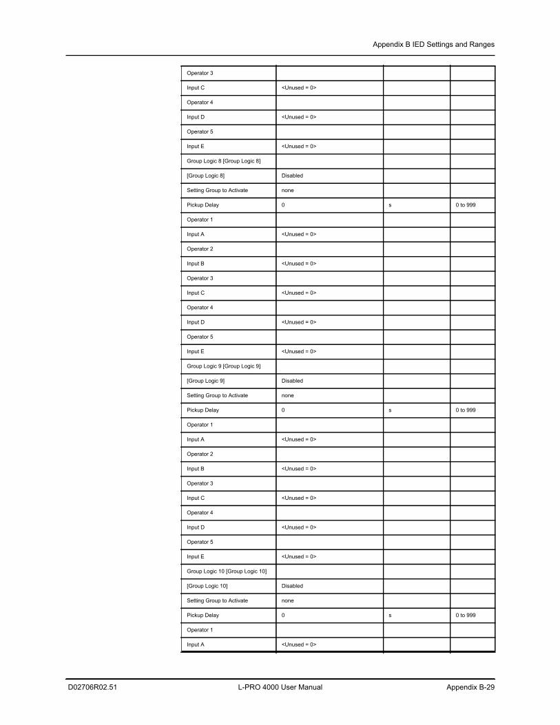
Appendix B IED Settings and Ranges
D02706R02.51 L-PRO 4000 User Manual Appendix B-29
Operator 3
Input C <Unused = 0>
Operator 4
Input D <Unused = 0>
Operator 5
Input E <Unused = 0>
Group Logic 8 [Group Logic 8]
[Group Logic 8] Disabled
Setting Group to Activate none
Pickup Delay 0 s 0 to 999
Operator 1
Input A <Unused = 0>
Operator 2
Input B <Unused = 0>
Operator 3
Input C <Unused = 0>
Operator 4
Input D <Unused = 0>
Operator 5
Input E <Unused = 0>
Group Logic 9 [Group Logic 9]
[Group Logic 9] Disabled
Setting Group to Activate none
Pickup Delay 0 s 0 to 999
Operator 1
Input A <Unused = 0>
Operator 2
Input B <Unused = 0>
Operator 3
Input C <Unused = 0>
Operator 4
Input D <Unused = 0>
Operator 5
Input E <Unused = 0>
Group Logic 10 [Group Logic 10]
[Group Logic 10] Disabled
Setting Group to Activate none
Pickup Delay 0 s 0 to 999
Operator 1
Input A <Unused = 0>
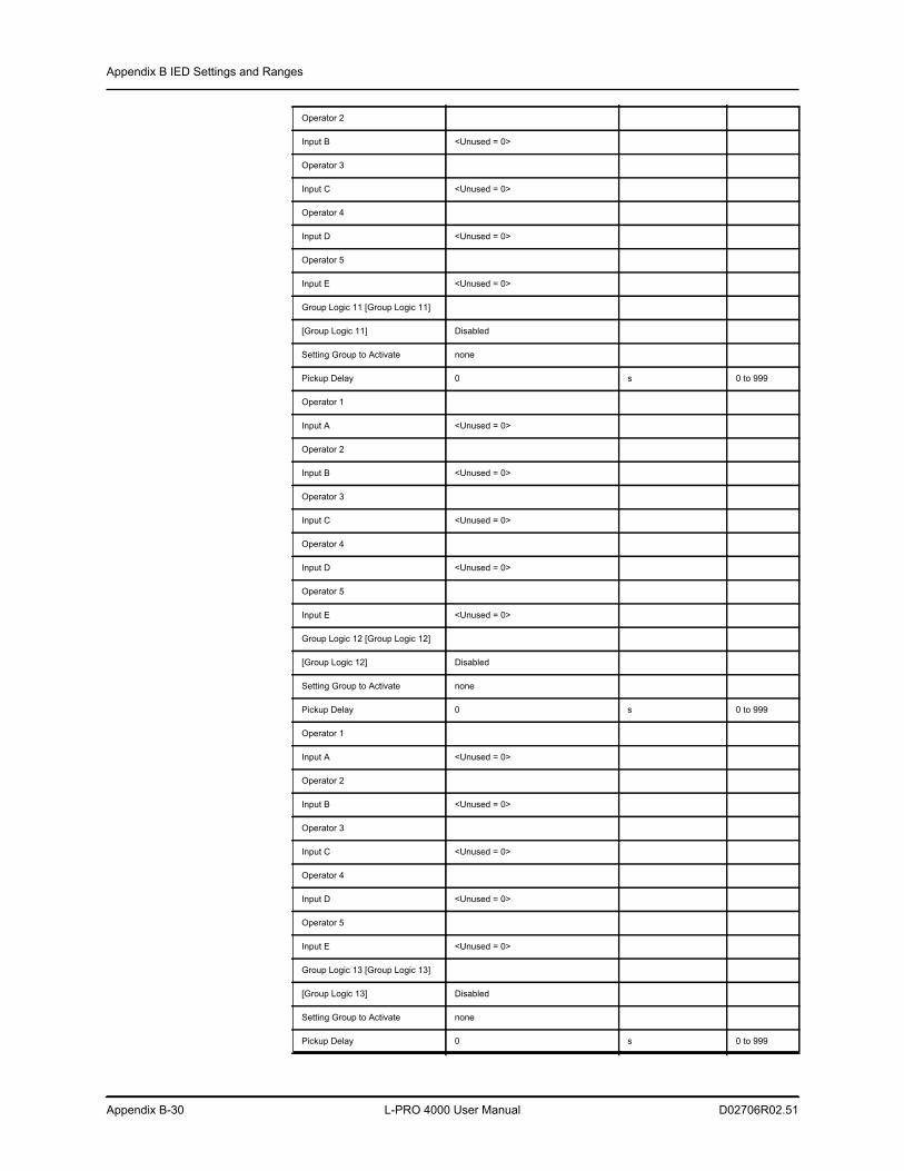
Appendix B IED Settings and Ranges
Appendix B-30 L-PRO 4000 User Manual D02706R02.51
Operator 2
Input B <Unused = 0>
Operator 3
Input C <Unused = 0>
Operator 4
Input D <Unused = 0>
Operator 5
Input E <Unused = 0>
Group Logic 11 [Group Logic 11]
[Group Logic 11] Disabled
Setting Group to Activate none
Pickup Delay 0 s 0 to 999
Operator 1
Input A <Unused = 0>
Operator 2
Input B <Unused = 0>
Operator 3
Input C <Unused = 0>
Operator 4
Input D <Unused = 0>
Operator 5
Input E <Unused = 0>
Group Logic 12 [Group Logic 12]
[Group Logic 12] Disabled
Setting Group to Activate none
Pickup Delay 0 s 0 to 999
Operator 1
Input A <Unused = 0>
Operator 2
Input B <Unused = 0>
Operator 3
Input C <Unused = 0>
Operator 4
Input D <Unused = 0>
Operator 5
Input E <Unused = 0>
Group Logic 13 [Group Logic 13]
[Group Logic 13] Disabled
Setting Group to Activate none
Pickup Delay 0 s 0 to 999
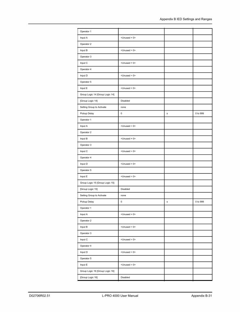
Appendix B IED Settings and Ranges
D02706R02.51 L-PRO 4000 User Manual Appendix B-31
Operator 1
Input A <Unused = 0>
Operator 2
Input B <Unused = 0>
Operator 3
Input C <Unused = 0>
Operator 4
Input D <Unused = 0>
Operator 5
Input E <Unused = 0>
Group Logic 14 [Group Logic 14]
[Group Logic 14] Disabled
Setting Group to Activate none
Pickup Delay 0 s 0 to 999
Operator 1
Input A <Unused = 0>
Operator 2
Input B <Unused = 0>
Operator 3
Input C <Unused = 0>
Operator 4
Input D <Unused = 0>
Operator 5
Input E <Unused = 0>
Group Logic 15 [Group Logic 15]
[Group Logic 15] Disabled
Setting Group to Activate none
Pickup Delay 0 s 0 to 999
Operator 1
Input A <Unused = 0>
Operator 2
Input B <Unused = 0>
Operator 3
Input C <Unused = 0>
Operator 4
Input D <Unused = 0>
Operator 5
Input E <Unused = 0>
Group Logic 16 [Group Logic 16]
[Group Logic 16] Disabled
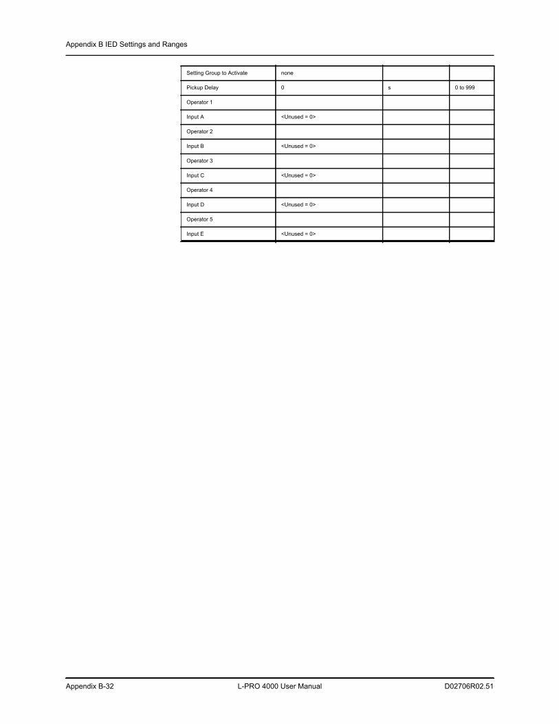
Appendix B IED Settings and Ranges
Appendix B-32 L-PRO 4000 User Manual D02706R02.51
Setting Group to Activate none
Pickup Delay 0 s 0 to 999
Operator 1
Input A <Unused = 0>
Operator 2
Input B <Unused = 0>
Operator 3
Input C <Unused = 0>
Operator 4
Input D <Unused = 0>
Operator 5
Input E <Unused = 0>
D02706R02.51 L-PRO 4000 User Manual Appendix C-1
Appendix C Hardware DescriptionThe relay is a complete line distance protection relay package designed and manufactured with high quality features and recording components. The fol-lowing information describes the main hardware components of the relay:
Main Processor Board (MPB)
The MPB has two processor sub-systems which control the operation of the en-tire relay: the DSP processor and the control processor. The DSP sub-system interfaces to the RAIB, the DIB and the OCB and manages the protection fea-tures of the relay. The control processor manages the user interface and system control features of the relay. Both subsystems operate independently of each other and will continue to function even if the other sub-system fails.
The MPB provides the following functionality:
• DSP processor subsystem which interfaces to the RAIB, the DIB and the OCB and manages the protection features of the relay, with:
• The floating point DSP to provide fast capture and manipulation of data.
• RAM and reprogrammable non-volatile Flash memory. Allows oper-ation independent of the control processor and supports field software updates.
• A control processor subsystem which manages the user interface and sys-tem control features of the relay, with
• RAM and reprogrammable non-volatile Flash memory. Allows oper-ation independent of the DSP processor and supports field software upgrades.
• Settings and recordings stored in non-volatile memory. • Runs a Real Time Operating System (RTOS). • Provides Ethernet ports and RS-232 ports for modem, SCADA, COM
and USB interfaces. • A time synchronism processor with automatic detection of modulated and
un-modulated IRIG-B
• A high speed link is provided between the DSP and control processor sub-systems.
• Sophisticated fault detection and “watchdog” recovery hardware
• The MPB also provides the power supply for the entire unit. The power supply operating range is 48-250 Vdc, 100-240 Vac, +/-10%, 50/60 Hz. This wide operating range provides easier installation by eliminating pow-er supply ordering options
Digital Input Board (DIB)
This board provides 9 digital input channels. Inputs are optically isolated, ex-ternally wetted, and factory preset to the customer’s requested voltage level of 48, 110/125 or 220/250 Vdc. This board interfaces to the MPB.
Appendix C Hardware Description
Appendix C-2 L-PRO 4000 User Manual D02706R02.51
Rear Panel Comm Board (RPCB)
The RPCB provides the relay with two RS-232 ports (Ports 122 and 123, DB9F), IRIG-B time synchronization input (Port 121, male BNC), internal modem connection (Port 118, RJ-11) and two Ethernet ports (Ports 119 and 120, RJ-45 or 100BASE-FX MM 1300nm ST, depending upon order specifi-cation). The RPCB interfaces to the MPB. Port 119 is the exception in that it interfaces to the GFPCB where it shares an internal switch with the front panel LAN port. The switch then interfaces to the MPB.
Output Contact Board (LOCB)
The LOCB provides 14 normally open contact outputs for relaying, alarms and control. It also provides one normally closed output contact for relay inopera-tive indication. This board interfaces to the MPB.
Output Contact Board (LOCBH)
The LOCBH provides the following output contacts for relaying, alarms and control:
• One normally closed relay inoperative indicator normal output contact
• 6 user-defined normal output contacts with both normally open and nor-mally closed terminals made available to the user
• 4 user-defined high current fast interrupting (HCFI) output contacts
The LOCBH interfaces to the MPB.
Digital Input/Output Board (DIGIO)
The DIGIO provides 11 digital input channels. Inputs are optically isolated, ex-ternally wetted, and factory preset to the customer's requested voltage level of 48, 110/125 or 220/250 Vdc. The DIGIO also provide 7 normally open contact outputs for relaying, alarms and control. This board interfaces to the MPB.
Relay AC Analog Sensor Boards (RASB)
Each relay has 3 RASBs. Two RASBs have 3 voltage transformer inputs and 3 current transformer inputs while the third RASB has 6 current transformer inputs. These boards provide 12 current and 6 voltage ac analog measurement inputs. The RASBs interface to the RAIB.
Relay AC Analog Input Board (RAIB)
The RAIB provides the analog to digital conversion of the 12 ac analog current inputs and the 6 ac analog voltage inputs. The sample rate is fixed at 96 sam-ples/cycle. Each channel is simultaneously sampled using 16-bit analog to dig-ital converters. The digitized data is sent to the MPB for processing and implementation of the protection algorithms.
Graphics Front Panel Comm Board (GFPCB)
The GFPCB provides the front panel USB and Ethernet ports, the front panel status LEDs and interfaces the MPB to the FPDB. The MPB controls the state of the LEDs.
Graphics Front Panel Display Board (GFPDB)
The GFPDB provides the 240x128 monochrome graphics front panel display and the keypad. The keypad is used to navigate the menus on the display to control relay operation by a local user.
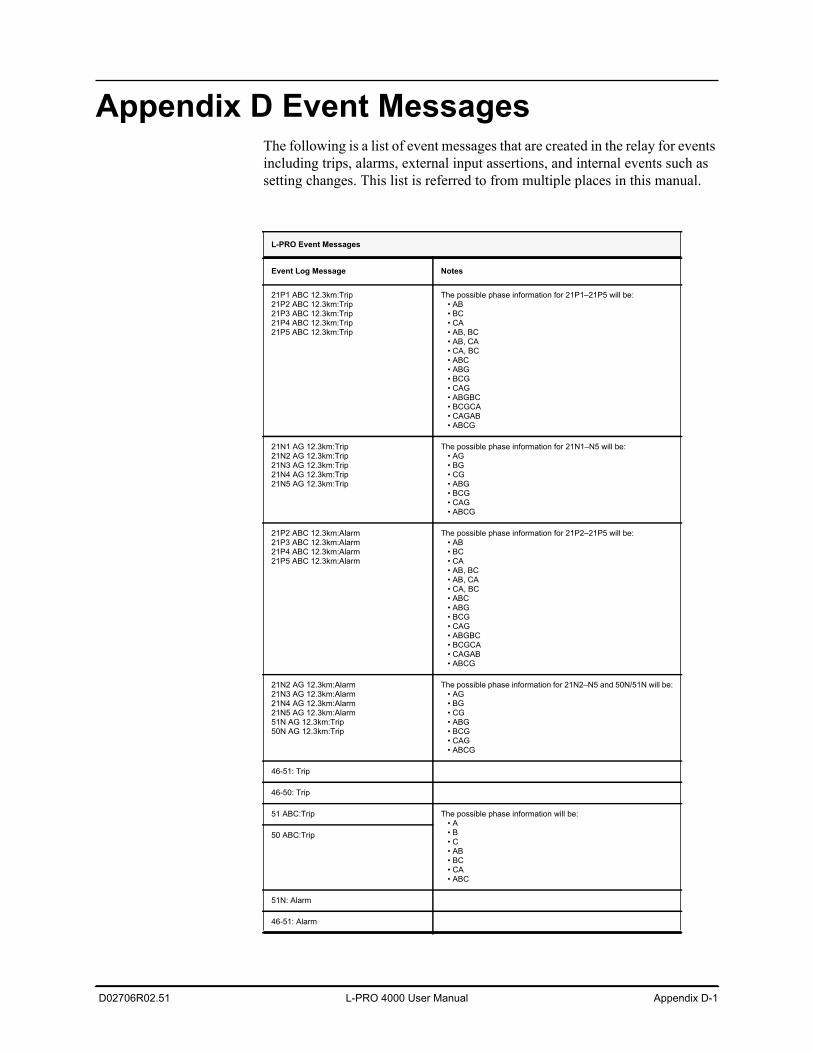
D02706R02.51 L-PRO 4000 User Manual Appendix D-1
Appendix D Event MessagesThe following is a list of event messages that are created in the relay for events including trips, alarms, external input assertions, and internal events such as setting changes. This list is referred to from multiple places in this manual.
L-PRO Event Messages
Event Log Message Notes
21P1 ABC 12.3km:Trip21P2 ABC 12.3km:Trip21P3 ABC 12.3km:Trip21P4 ABC 12.3km:Trip21P5 ABC 12.3km:Trip
The possible phase information for 21P1–21P5 will be: • AB • BC • CA • AB, BC • AB, CA • CA, BC • ABC • ABG • BCG • CAG • ABGBC • BCGCA • CAGAB • ABCG
21N1 AG 12.3km:Trip21N2 AG 12.3km:Trip21N3 AG 12.3km:Trip21N4 AG 12.3km:Trip21N5 AG 12.3km:Trip
The possible phase information for 21N1–N5 will be: • AG • BG • CG • ABG • BCG • CAG • ABCG
21P2 ABC 12.3km:Alarm21P3 ABC 12.3km:Alarm21P4 ABC 12.3km:Alarm21P5 ABC 12.3km:Alarm
The possible phase information for 21P2–21P5 will be: • AB • BC • CA • AB, BC • AB, CA • CA, BC • ABC • ABG • BCG • CAG • ABGBC • BCGCA • CAGAB • ABCG
21N2 AG 12.3km:Alarm21N3 AG 12.3km:Alarm21N4 AG 12.3km:Alarm21N5 AG 12.3km:Alarm51N AG 12.3km:Trip50N AG 12.3km:Trip
The possible phase information for 21N2–N5 and 50N/51N will be: • AG • BG • CG • ABG • BCG • CAG • ABCG
46-51: Trip
46-50: Trip
51 ABC:Trip The possible phase information will be: • A • B • C • AB • BC • CA • ABC
50 ABC:Trip
51N: Alarm
46-51: Alarm
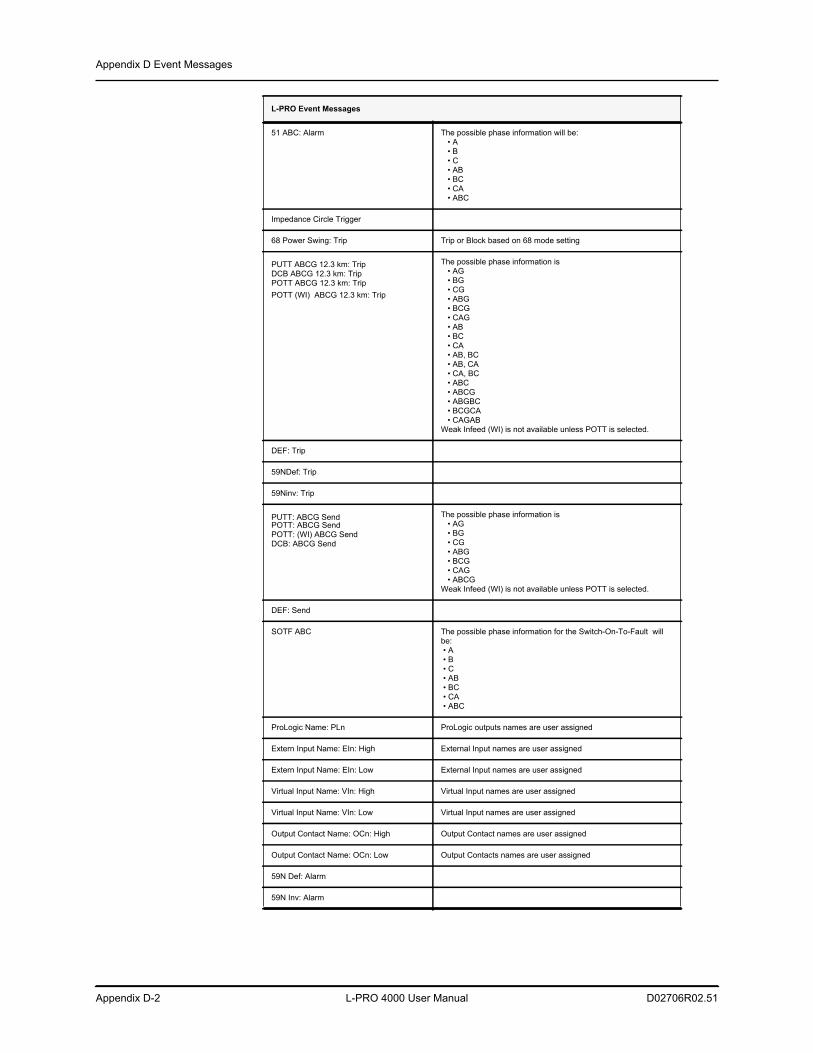
Appendix D Event Messages
Appendix D-2 L-PRO 4000 User Manual D02706R02.51
51 ABC: Alarm The possible phase information will be: • A • B • C • AB • BC • CA • ABC
Impedance Circle Trigger
68 Power Swing: Trip Trip or Block based on 68 mode setting
PUTT ABCG 12.3 km: TripDCB ABCG 12.3 km: TripPOTT ABCG 12.3 km: TripPOTT (WI) ABCG 12.3 km: Trip
The possible phase information is • AG • BG • CG • ABG • BCG • CAG • AB • BC • CA • AB, BC • AB, CA • CA, BC • ABC • ABCG • ABGBC • BCGCA • CAGABWeak Infeed (WI) is not available unless POTT is selected.
DEF: Trip
59NDef: Trip
59Ninv: Trip
PUTT: ABCG SendPOTT: ABCG SendPOTT: (WI) ABCG Send DCB: ABCG Send
The possible phase information is • AG • BG • CG • ABG • BCG • CAG • ABCGWeak Infeed (WI) is not available unless POTT is selected.
DEF: Send
SOTF ABC The possible phase information for the Switch-On-To-Fault will be: • A • B • C • AB • BC • CA • ABC
ProLogic Name: PLn ProLogic outputs names are user assigned
Extern Input Name: EIn: High External Input names are user assigned
Extern Input Name: EIn: Low External Input names are user assigned
Virtual Input Name: VIn: High Virtual Input names are user assigned
Virtual Input Name: VIn: Low Virtual Input names are user assigned
Output Contact Name: OCn: High Output Contact names are user assigned
Output Contact Name: OCn: Low Output Contacts names are user assigned
59N Def: Alarm
59N Inv: Alarm
L-PRO Event Messages
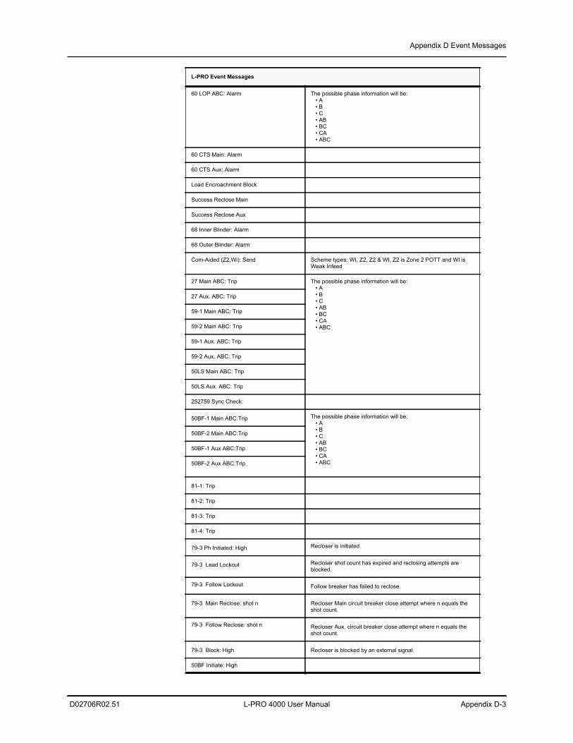
Appendix D Event Messages
D02706R02.51 L-PRO 4000 User Manual Appendix D-3
60 LOP ABC: Alarm The possible phase information will be: • A • B • C • AB • BC • CA • ABC
60 CTS Main: Alarm
60 CTS Aux: Alarm
Load Encroachment Block
Success Reclose Main
Success Reclose Aux
68 Inner Blinder: Alarm
68 Outer Blinder: Alarm
Com-Aided (Z2,Wi): Send Scheme types: WI, Z2, Z2 & WI, Z2 is Zone 2 POTT and WI is Weak Infeed
27 Main ABC: Trip The possible phase information will be: • A • B • C • AB • BC • CA • ABC
27 Aux. ABC: Trip
59-1 Main ABC: Trip
59-2 Main ABC: Trip
59-1 Aux. ABC: Trip
59-2 Aux. ABC: Trip
50LS Main ABC: Trip
50LS Aux. ABC: Trip
252759 Sync Check:
50BF-1 Main ABC:Trip The possible phase information will be: • A • B • C • AB • BC • CA • ABC
50BF-2 Main ABC:Trip
50BF-1 Aux ABC:Trip
50BF-2 Aux ABC:Trip
81-1: Trip
81-2: Trip
81-3: Trip
81-4: Trip
79-3 Ph Initiated: High Recloser is initiated.
79-3 Lead Lockout Recloser shot count has expired and reclosing attempts are blocked.
79-3 Follow Lockout Follow breaker has failed to reclose.
79-3 Main Reclose: shot n Recloser Main circuit breaker close attempt where n equals the shot count.
79-3 Follow Reclose: shot n Recloser Aux. circuit breaker close attempt where n equals the shot count.
79-3 Block: High Recloser is blocked by an external signal.
50BF Initiate: High
L-PRO Event Messages
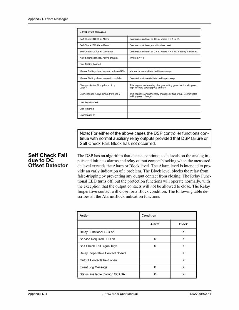
Appendix D Event Messages
Appendix D-4 L-PRO 4000 User Manual D02706R02.51
Self Check Fail due to DC Offset Detector
The DSP has an algorithm that detects continuous dc levels on the analog in-puts and initiates alarms and relay output contact blocking when the measured dc level exceeds the Alarm or Block level. The Alarm level is intended to pro-vide an early indication of a problem. The Block level blocks the relay from false-tripping by preventing any output contact from closing. The Relay Func-tional LED turns off, but the protection functions will operate normally, with the exception that the output contacts will not be allowed to close. The Relay Inoperative contact will close for a Block condition. The following table de-scribes all the Alarm/Block indication functions
Self Check: DC Ch.n: Alarm Continuous dc level on Ch. n, where n = 1 to 18.
Self Check: DC Alarm Reset Continuous dc level, condition has reset.
Self Check: DC Ch.n: O/P Block Continuous dc level on Ch. n, where n = 1 to 18. Relay is blocked.
New Settings loaded, Active group n. Where n = 1-8
New Setting Loaded
Manual Settings Load request, activate SGn Manual or user-initiated settings change.
Manual Settings Load request completed Completion of user-initiated settings change.
Changed Active Group from x to y Logic n
This happens when relay changes setting group. Automatic group logic initiated setting group change
User changed Active Group from x to y This happens when the relay changes setting group. User initiated setting group change
Unit Recalibrated
Unit restarted
User logged In
Note: For either of the above cases the DSP controller functions con-tinue with normal auxiliary relay outputs provided that DSP failure or Self Check Fail: Block has not occurred.
L-PRO Event Messages
Action Condition
Alarm Block
Relay Functional LED off X
Service Required LED on X X
Self Check Fail Signal high X X
Relay Inoperative Contact closed X
Output Contacts held open X
Event Log Message X X
Status available through SCADA X X
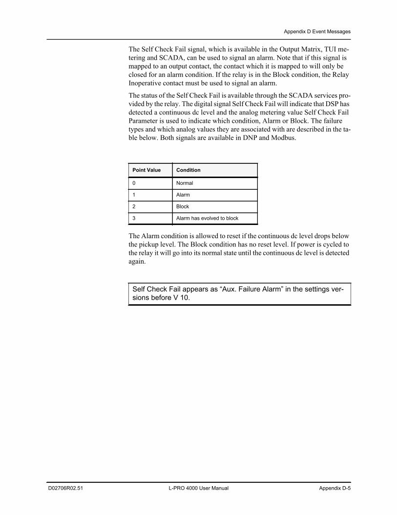
Appendix D Event Messages
D02706R02.51 L-PRO 4000 User Manual Appendix D-5
The Self Check Fail signal, which is available in the Output Matrix, TUI me-tering and SCADA, can be used to signal an alarm. Note that if this signal is mapped to an output contact, the contact which it is mapped to will only be closed for an alarm condition. If the relay is in the Block condition, the Relay Inoperative contact must be used to signal an alarm.
The status of the Self Check Fail is available through the SCADA services pro-vided by the relay. The digital signal Self Check Fail will indicate that DSP has detected a continuous dc level and the analog metering value Self Check Fail Parameter is used to indicate which condition, Alarm or Block. The failure types and which analog values they are associated with are described in the ta-ble below. Both signals are available in DNP and Modbus.
The Alarm condition is allowed to reset if the continuous dc level drops below the pickup level. The Block condition has no reset level. If power is cycled to the relay it will go into its normal state until the continuous dc level is detected again.
Point Value Condition
0 Normal
1 Alarm
2 Block
3 Alarm has evolved to block
Self Check Fail appears as “Aux. Failure Alarm” in the settings ver-sions before V 10.

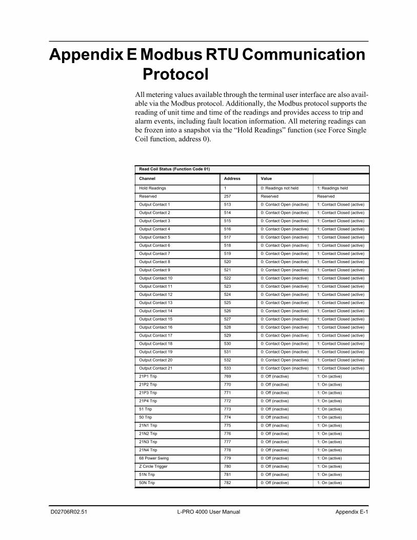
D02706R02.51 L-PRO 4000 User Manual Appendix E-1
Appendix E Modbus RTU Communication Protocol
All metering values available through the terminal user interface are also avail-able via the Modbus protocol. Additionally, the Modbus protocol supports the reading of unit time and time of the readings and provides access to trip and alarm events, including fault location information. All metering readings can be frozen into a snapshot via the “Hold Readings” function (see Force Single Coil function, address 0).
Read Coil Status (Function Code 01)
Channel Address Value
Hold Readings 1 0: Readings not held 1: Readings held
Reserved 257 Reserved Reserved
Output Contact 1 513 0: Contact Open (inactive) 1: Contact Closed (active)
Output Contact 2 514 0: Contact Open (inactive) 1: Contact Closed (active)
Output Contact 3 515 0: Contact Open (inactive) 1: Contact Closed (active)
Output Contact 4 516 0: Contact Open (inactive) 1: Contact Closed (active)
Output Contact 5 517 0: Contact Open (inactive) 1: Contact Closed (active)
Output Contact 6 518 0: Contact Open (inactive) 1: Contact Closed (active)
Output Contact 7 519 0: Contact Open (inactive) 1: Contact Closed (active)
Output Contact 8 520 0: Contact Open (inactive) 1: Contact Closed (active)
Output Contact 9 521 0: Contact Open (inactive) 1: Contact Closed (active)
Output Contact 10 522 0: Contact Open (inactive) 1: Contact Closed (active)
Output Contact 11 523 0: Contact Open (inactive) 1: Contact Closed (active)
Output Contact 12 524 0: Contact Open (inactive) 1: Contact Closed (active)
Output Contact 13 525 0: Contact Open (inactive) 1: Contact Closed (active)
Output Contact 14 526 0: Contact Open (inactive) 1: Contact Closed (active)
Output Contact 15 527 0: Contact Open (inactive) 1: Contact Closed (active)
Output Contact 16 528 0: Contact Open (inactive) 1: Contact Closed (active)
Output Contact 17 529 0: Contact Open (inactive) 1: Contact Closed (active)
Output Contact 18 530 0: Contact Open (inactive) 1: Contact Closed (active)
Output Contact 19 531 0: Contact Open (inactive) 1: Contact Closed (active)
Output Contact 20 532 0: Contact Open (inactive) 1: Contact Closed (active)
Output Contact 21 533 0: Contact Open (inactive) 1: Contact Closed (active)
21P1 Trip 769 0: Off (inactive) 1: On (active)
21P2 Trip 770 0: Off (inactive) 1: On (active)
21P3 Trip 771 0: Off (inactive) 1: On (active)
21P4 Trip 772 0: Off (inactive) 1: On (active)
51 Trip 773 0: Off (inactive) 1: On (active)
50 Trip 774 0: Off (inactive) 1: On (active)
21N1 Trip 775 0: Off (inactive) 1: On (active)
21N2 Trip 776 0: Off (inactive) 1: On (active)
21N3 Trip 777 0: Off (inactive) 1: On (active)
21N4 Trip 778 0: Off (inactive) 1: On (active)
68 Power Swing 779 0: Off (inactive) 1: On (active)
Z Circle Trigger 780 0: Off (inactive) 1: On (active)
51N Trip 781 0: Off (inactive) 1: On (active)
50N Trip 782 0: Off (inactive) 1: On (active)
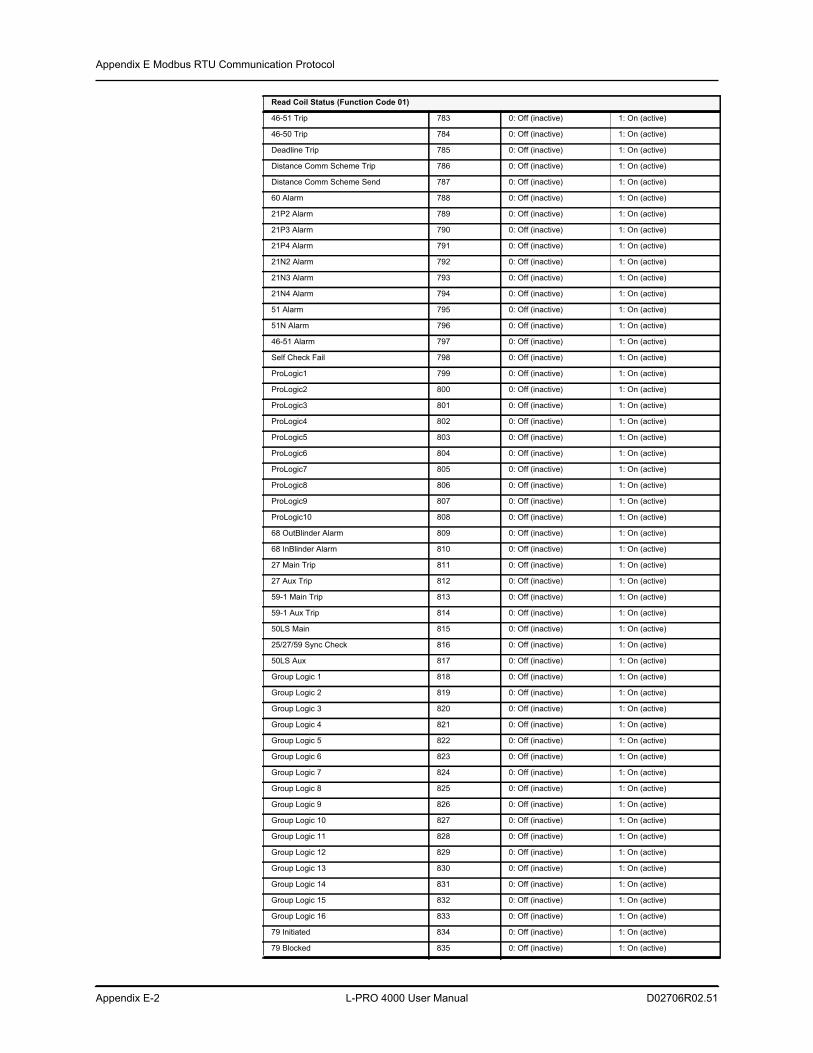
Appendix E Modbus RTU Communication Protocol
Appendix E-2 L-PRO 4000 User Manual D02706R02.51
46-51 Trip 783 0: Off (inactive) 1: On (active)
46-50 Trip 784 0: Off (inactive) 1: On (active)
Deadline Trip 785 0: Off (inactive) 1: On (active)
Distance Comm Scheme Trip 786 0: Off (inactive) 1: On (active)
Distance Comm Scheme Send 787 0: Off (inactive) 1: On (active)
60 Alarm 788 0: Off (inactive) 1: On (active)
21P2 Alarm 789 0: Off (inactive) 1: On (active)
21P3 Alarm 790 0: Off (inactive) 1: On (active)
21P4 Alarm 791 0: Off (inactive) 1: On (active)
21N2 Alarm 792 0: Off (inactive) 1: On (active)
21N3 Alarm 793 0: Off (inactive) 1: On (active)
21N4 Alarm 794 0: Off (inactive) 1: On (active)
51 Alarm 795 0: Off (inactive) 1: On (active)
51N Alarm 796 0: Off (inactive) 1: On (active)
46-51 Alarm 797 0: Off (inactive) 1: On (active)
Self Check Fail 798 0: Off (inactive) 1: On (active)
ProLogic1 799 0: Off (inactive) 1: On (active)
ProLogic2 800 0: Off (inactive) 1: On (active)
ProLogic3 801 0: Off (inactive) 1: On (active)
ProLogic4 802 0: Off (inactive) 1: On (active)
ProLogic5 803 0: Off (inactive) 1: On (active)
ProLogic6 804 0: Off (inactive) 1: On (active)
ProLogic7 805 0: Off (inactive) 1: On (active)
ProLogic8 806 0: Off (inactive) 1: On (active)
ProLogic9 807 0: Off (inactive) 1: On (active)
ProLogic10 808 0: Off (inactive) 1: On (active)
68 OutBlinder Alarm 809 0: Off (inactive) 1: On (active)
68 InBlinder Alarm 810 0: Off (inactive) 1: On (active)
27 Main Trip 811 0: Off (inactive) 1: On (active)
27 Aux Trip 812 0: Off (inactive) 1: On (active)
59-1 Main Trip 813 0: Off (inactive) 1: On (active)
59-1 Aux Trip 814 0: Off (inactive) 1: On (active)
50LS Main 815 0: Off (inactive) 1: On (active)
25/27/59 Sync Check 816 0: Off (inactive) 1: On (active)
50LS Aux 817 0: Off (inactive) 1: On (active)
Group Logic 1 818 0: Off (inactive) 1: On (active)
Group Logic 2 819 0: Off (inactive) 1: On (active)
Group Logic 3 820 0: Off (inactive) 1: On (active)
Group Logic 4 821 0: Off (inactive) 1: On (active)
Group Logic 5 822 0: Off (inactive) 1: On (active)
Group Logic 6 823 0: Off (inactive) 1: On (active)
Group Logic 7 824 0: Off (inactive) 1: On (active)
Group Logic 8 825 0: Off (inactive) 1: On (active)
Group Logic 9 826 0: Off (inactive) 1: On (active)
Group Logic 10 827 0: Off (inactive) 1: On (active)
Group Logic 11 828 0: Off (inactive) 1: On (active)
Group Logic 12 829 0: Off (inactive) 1: On (active)
Group Logic 13 830 0: Off (inactive) 1: On (active)
Group Logic 14 831 0: Off (inactive) 1: On (active)
Group Logic 15 832 0: Off (inactive) 1: On (active)
Group Logic 16 833 0: Off (inactive) 1: On (active)
79 Initiated 834 0: Off (inactive) 1: On (active)
79 Blocked 835 0: Off (inactive) 1: On (active)
Read Coil Status (Function Code 01)
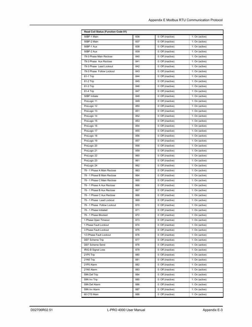
Appendix E Modbus RTU Communication Protocol
D02706R02.51 L-PRO 4000 User Manual Appendix E-3
50BF-1 Main 836 0: Off (inactive) 1: On (active)
50BF-2 Main 837 0: Off (inactive) 1: On (active)
50BF-1 Aux 838 0: Off (inactive) 1: On (active)
50BF-2 Aux 839 0: Off (inactive) 1: On (active)
79-3 Phase Main Reclose 840 0: Off (inactive) 1: On (active)
79-3 Phase Aux Reclose 841 0: Off (inactive) 1: On (active)
79-3 Phase Lead Lockout 842 0: Off (inactive) 1: On (active)
79-3 Phase Follow Lockout 843 0: Off (inactive) 1: On (active)
81-1 Trip 844 0: Off (inactive) 1: On (active)
81-2 Trip 845 0: Off (inactive) 1: On (active)
81-3 Trip 846 0: Off (inactive) 1: On (active)
81-4 Trip 847 0: Off (inactive) 1: On (active)
50BF Initiate 848 0: Off (inactive) 1: On (active)
ProLogic 11 849 0: Off (inactive) 1: On (active)
ProLogic 12 850 0: Off (inactive) 1: On (active)
ProLogic 13 851 0: Off (inactive) 1: On (active)
ProLogic 14 852 0: Off (inactive) 1: On (active)
ProLogic 15 853 0: Off (inactive) 1: On (active)
ProLogic 16 854 0: Off (inactive) 1: On (active)
ProLogic 17 855 0: Off (inactive) 1: On (active)
ProLogic 18 856 0: Off (inactive) 1: On (active)
ProLogic 19 857 0: Off (inactive) 1: On (active)
ProLogic 20 858 0: Off (inactive) 1: On (active)
ProLogic 21 859 0: Off (inactive) 1: On (active)
ProLogic 22 860 0: Off (inactive) 1: On (active)
ProLogic 23 861 0: Off (inactive) 1: On (active)
ProLogic 24 862 0: Off (inactive) 1: On (active)
79 - 1 Phase A Main Reclose 863 0: Off (inactive) 1: On (active)
79 - 1 Phase B Main Reclose 864 0: Off (inactive) 1: On (active)
79 - 1 Phase C Main Reclose 865 0: Off (inactive) 1: On (active)
79 - 1 Phase A Aux Reclose 866 0: Off (inactive) 1: On (active)
79 - 1 Phase B Aux Reclose 867 0: Off (inactive) 1: On (active)
79 - 1 Phase C Aux Reclose 868 0: Off (inactive) 1: On (active)
79 - 1 Phase Lead Lockout 869 0: Off (inactive) 1: On (active)
79 - 1 Phase Follow Lockout 870 0: Off (inactive) 1: On (active)
79 - 1 Phase Initiated 871 0: Off (inactive) 1: On (active)
79 - 1 Phase Blocked 872 0: Off (inactive) 1: On (active)
1 Phase Open Timeout 873 0: Off (inactive) 1: On (active)
1 Phase Fault Lockout 874 0: Off (inactive) 1: On (active)
3 Phase Fault Lockout 875 0: Off (inactive) 1: On (active)
1/3 Phase Fault Lockout 876 0: Off (inactive) 1: On (active)
DEF Scheme Trip 877 0: Off (inactive) 1: On (active)
DEF Scheme Send 878 0: Off (inactive) 1: On (active)
IRIG-B Signal Loss 879 0: Off (inactive) 1: On (active)
21P5 Trip 880 0: Off (inactive) 1: On (active)
21N5 Trip 881 0: Off (inactive) 1: On (active)
21P5 Alarm 882 0: Off (inactive) 1: On (active)
21N5 Alarm 883 0: Off (inactive) 1: On (active)
59N Def Trip 884 0: Off (inactive) 1: On (active)
59N Inv Trip 885 0: Off (inactive) 1: On (active)
59N Def Alarm 886 0: Off (inactive) 1: On (active)
59N Inv Alarm 887 0: Off (inactive) 1: On (active)
60 CTS Main 888 0: Off (inactive) 1: On (active)
Read Coil Status (Function Code 01)
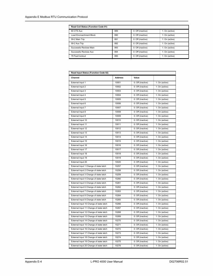
Appendix E Modbus RTU Communication Protocol
Appendix E-4 L-PRO 4000 User Manual D02706R02.51
60 CTS Aux 889 0: Off (inactive) 1: On (active)
Load Encroachment Block 890 0: Off (inactive) 1: On (active)
59-2 Main Trip 891 0: Off (inactive) 1: On (active)
59-2 Aux Trip 892 0: Off (inactive) 1: On (active)
Successful Reclose Main 893 0: Off (inactive) 1: On (active)
Successful Reclose Aux 894 0: Off (inactive) 1: On (active)
79 Fault lockout 895 0: Off (inactive) 1: On (active)
Read Input Status (Function Code 02)
Channel Address Value
External Input 1 10001 0: Off (inactive) 1: On (active)
External Input 2 10002 0: Off (inactive) 1: On (active)
External Input 3 10003 0: Off (inactive) 1: On (active)
External Input 4 10004 0: Off (inactive) 1: On (active)
External Input 5 10005 0: Off (inactive) 1: On (active)
External Input 6 10006 0: Off (inactive) 1: On (active)
External Input 7 10007 0: Off (inactive) 1: On (active)
External Input 8 10008 0: Off (inactive) 1: On (active)
External Input 9 10009 0: Off (inactive) 1: On (active)
External Input 10 10010 0: Off (inactive) 1: On (active)
External Input 11 10011 0: Off (inactive) 1: On (active)
External Input 12 10012 0: Off (inactive) 1: On (active)
External Input 13 10013 0: Off (inactive) 1: On (active)
External Input 14 10014 0: Off (inactive) 1: On (active)
External Input 15 10015 0: Off (inactive) 1: On (active)
External Input 16 10016 0: Off (inactive) 1: On (active)
External Input 17 10017 0: Off (inactive) 1: On (active)
External Input 18 10018 0: Off (inactive) 1: On (active)
External Input 19 10019 0: Off (inactive) 1: On (active)
External Input 20 10020 0: Off (inactive) 1: On (active)
External Input 1 Change of state latch 10257 0: Off (inactive) 1: On (active)
External Input 2 Change of state latch 10258 0: Off (inactive) 1: On (active)
External Input 3 Change of state latch 10259 0: Off (inactive) 1: On (active)
External Input 4 Change of state latch 10260 0: Off (inactive) 1: On (active)
External Input 5 Change of state latch 10261 0: Off (inactive) 1: On (active)
External Input 6 Change of state latch 10262 0: Off (inactive) 1: On (active)
External Input 7 Change of state latch 10263 0: Off (inactive) 1: On (active)
External Input 8 Change of state latch 10264 0: Off (inactive) 1: On (active)
External Input 9 Change of state latch 10265 0: Off (inactive) 1: On (active)
External Input 10 Change of state latch 10266 0: Off (inactive) 1: On (active)
External Input 11 Change of state latch 10267 0: Off (inactive) 1: On (active)
External Input 12 Change of state latch 10268 0: Off (inactive) 1: On (active)
External Input 13 Change of state latch 10269 0: Off (inactive) 1: On (active)
External Input 14 Change of state latch 10270 0: Off (inactive) 1: On (active)
External Input 15 Change of state latch 10271 0: Off (inactive) 1: On (active)
External Input 16 Change of state latch 10272 0: Off (inactive) 1: On (active)
External Input 17 Change of state latch 10273 0: Off (inactive) 1: On (active)
External Input 18 Change of state latch 10274 0: Off (inactive) 1: On (active)
External Input 19 Change of state latch 10275 0: Off (inactive) 1: On (active)
External Input 20 Change of state latch 10276 0: Off (inactive) 1: On (active)
Read Coil Status (Function Code 01)
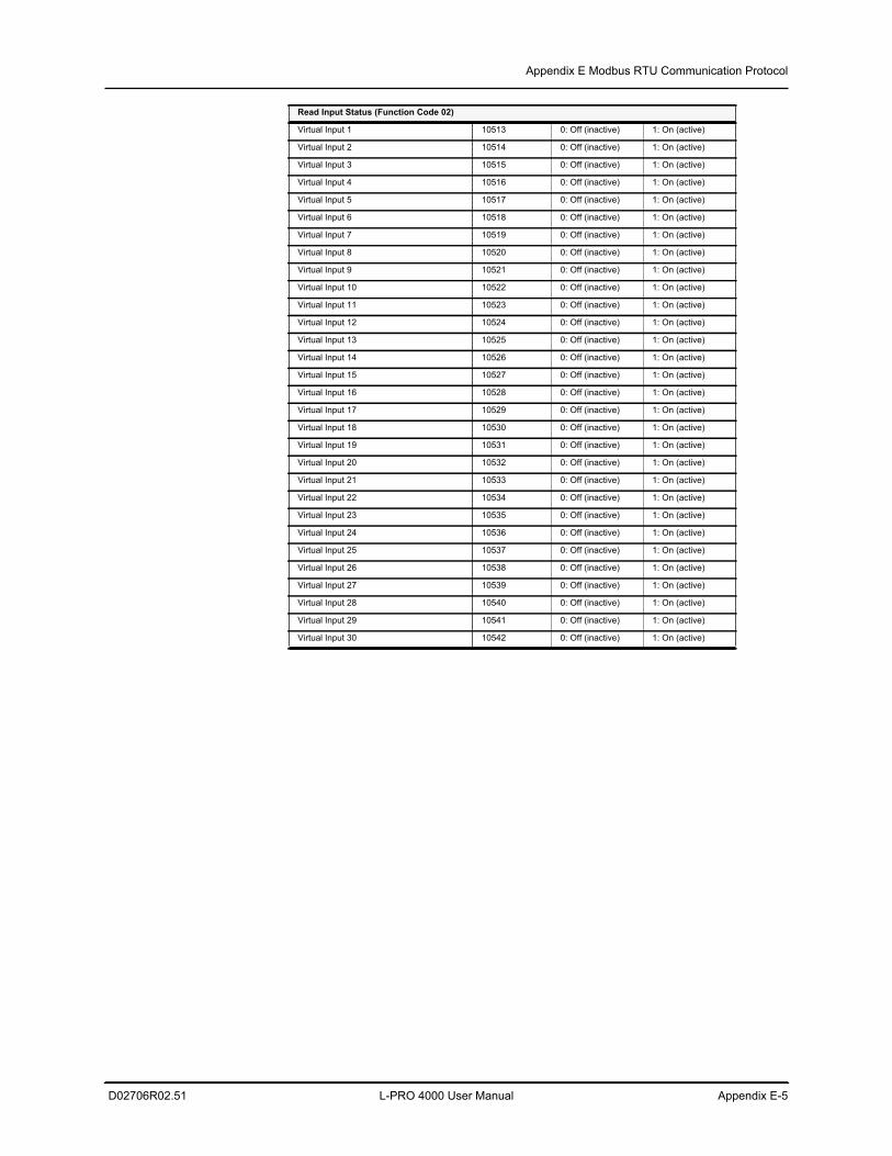
Appendix E Modbus RTU Communication Protocol
D02706R02.51 L-PRO 4000 User Manual Appendix E-5
Virtual Input 1 10513 0: Off (inactive) 1: On (active)
Virtual Input 2 10514 0: Off (inactive) 1: On (active)
Virtual Input 3 10515 0: Off (inactive) 1: On (active)
Virtual Input 4 10516 0: Off (inactive) 1: On (active)
Virtual Input 5 10517 0: Off (inactive) 1: On (active)
Virtual Input 6 10518 0: Off (inactive) 1: On (active)
Virtual Input 7 10519 0: Off (inactive) 1: On (active)
Virtual Input 8 10520 0: Off (inactive) 1: On (active)
Virtual Input 9 10521 0: Off (inactive) 1: On (active)
Virtual Input 10 10522 0: Off (inactive) 1: On (active)
Virtual Input 11 10523 0: Off (inactive) 1: On (active)
Virtual Input 12 10524 0: Off (inactive) 1: On (active)
Virtual Input 13 10525 0: Off (inactive) 1: On (active)
Virtual Input 14 10526 0: Off (inactive) 1: On (active)
Virtual Input 15 10527 0: Off (inactive) 1: On (active)
Virtual Input 16 10528 0: Off (inactive) 1: On (active)
Virtual Input 17 10529 0: Off (inactive) 1: On (active)
Virtual Input 18 10530 0: Off (inactive) 1: On (active)
Virtual Input 19 10531 0: Off (inactive) 1: On (active)
Virtual Input 20 10532 0: Off (inactive) 1: On (active)
Virtual Input 21 10533 0: Off (inactive) 1: On (active)
Virtual Input 22 10534 0: Off (inactive) 1: On (active)
Virtual Input 23 10535 0: Off (inactive) 1: On (active)
Virtual Input 24 10536 0: Off (inactive) 1: On (active)
Virtual Input 25 10537 0: Off (inactive) 1: On (active)
Virtual Input 26 10538 0: Off (inactive) 1: On (active)
Virtual Input 27 10539 0: Off (inactive) 1: On (active)
Virtual Input 28 10540 0: Off (inactive) 1: On (active)
Virtual Input 29 10541 0: Off (inactive) 1: On (active)
Virtual Input 30 10542 0: Off (inactive) 1: On (active)
Read Input Status (Function Code 02)
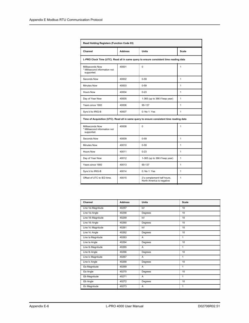
Appendix E Modbus RTU Communication Protocol
Appendix E-6 L-PRO 4000 User Manual D02706R02.51
Read Holding Registers (Function Code 03)
Channel Address Units Scale
L-PRO Clock Time (UTC). Read all in same query to ensure consistent time reading data
Milliseconds Now* Millisecond information not
supported.
40001 0 1
Seconds Now 40002 0-59 1
Minutes Now 40003 0-59 1
Hours Now 40004 0-23 1
Day of Year Now 40005 1-365 (up to 366 if leap year) 1
Years since 1900 40006 90-137 1
Sync’d to IRIG-B 40007 0: No 1: Yes 1
Time of Acquisition (UTC). Read all in same query to ensure consistent time reading data
Milliseconds Now* Millisecond information not
supported.
40008 0 1
Seconds Now 40009 0-59 1
Minutes Now 40010 0-59 1
Hours Now 40011 0-23 1
Day of Year Now 40012 1-365 (up to 366 if leap year) 1
Years since 1900 40013 90-137 1
Sync’d to IRIG-B 40014 0: No 1: Yes 1
Offset of UTC to IED time. 40015 2’s complement half hours, North America is negative
1
Channel Address Units Scale
Line Va Magnitude 40257 kV 10
Line Va Angle 40258 Degrees 10
Line Vb Magnitude 40259 kV 10
Line Vb Angle 40260 Degrees 10
Line Vc Magnitude 40261 kV 10
Line Vc Angle 40262 Degrees 10
Line Ia Magnitude 40263 A 1
Line Ia Angle 40264 Degrees 10
Line Ib Magnitude 40265 A 1
Line Ib Angle 40266 Degrees 10
Line Ic Magnitude 40267 A 1
Line Ic Angle 40268 Degrees 10
I2a Magnitude 40269 A 1
I2a Angle 40270 Degrees 10
I2b Magnitude 40271 A 1
I2b Angle 40272 Degrees 10
I2c Magnitude 40273 A 1
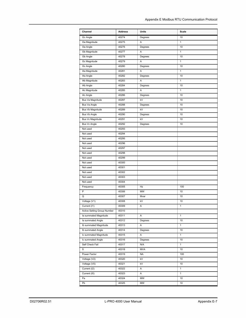
Appendix E Modbus RTU Communication Protocol
D02706R02.51 L-PRO 4000 User Manual Appendix E-7
I2c Angle 40274 Degrees 10
I3a Magnitude 40275 A 1
I3a Angle 40276 Degrees 10
I3b Magnitude 40277 A 1
I3b Angle 40278 Degrees 10
I3c Magnitude 40279 A 1
I3c Angle 40280 Degrees 10
I4a Magnitude 40281 A 1
I4a Angle 40282 Degrees 10
I4b Magnitude 40283 A 1
I4b Angle 40284 Degrees 10
I4c Magnitude 40285 A 1
I4c Angle 40286 Degrees 10
Bus Va Magnitude 40287 kV 10
Bus Va Angle 40288 Degrees 10
Bus Vb Magnitude 40289 kV 10
Bus Vb Angle 40290 Degrees 10
Bus Vc Magnitude 40291 kV 10
Bus Vc Angle 40292 Degrees 10
Not used 40293
Not used 40294
Not used 40295
Not used 40296
Not used 40297
Not used 40298
Not used 40299
Not used 40300
Not used 40301
Not used 40302
Not used 40303
Not used 40304
Frequency 40305 Hz 100
P 40306 MW 10
Q 40307 Mvar 10
Voltage (V1) 40308 kV 10
Current (I1) 40309 A 1
Active Setting Group Number 40310
Ia summated Magnitude 40311 A 1
Ia summated Angle 40312 Degrees 10
Ib summated Magnitude 40313 A 1
Ib summated Angle 40314 Degrees 10
Ic summated Magnitude 40315 A 1
Ic summated Angle 40316 Degrees 10
Self Check Fail 40317 N/A 1
S 40318 MVA 10
Power Factor 40319 NA 100
Voltage (V2) 40320 kV 10
Voltage (V0) 40321 kV 10
Current (I2) 40322 A 1
Current (I0) 40323 A 1
Pa 40324 MW 10
Pb 40325 MW 10
Channel Address Units Scale
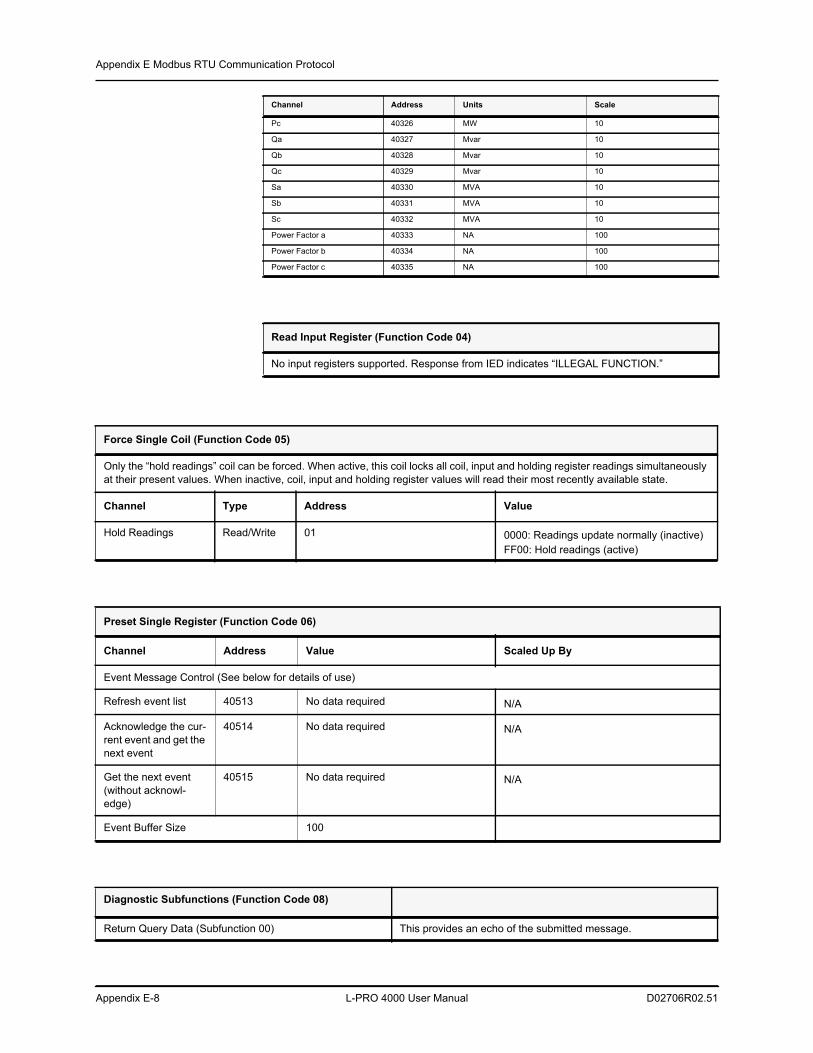
Appendix E Modbus RTU Communication Protocol
Appendix E-8 L-PRO 4000 User Manual D02706R02.51
Pc 40326 MW 10
Qa 40327 Mvar 10
Qb 40328 Mvar 10
Qc 40329 Mvar 10
Sa 40330 MVA 10
Sb 40331 MVA 10
Sc 40332 MVA 10
Power Factor a 40333 NA 100
Power Factor b 40334 NA 100
Power Factor c 40335 NA 100
Read Input Register (Function Code 04)
No input registers supported. Response from IED indicates “ILLEGAL FUNCTION.”
Channel Address Units Scale
Force Single Coil (Function Code 05)
Only the “hold readings” coil can be forced. When active, this coil locks all coil, input and holding register readings simultaneously at their present values. When inactive, coil, input and holding register values will read their most recently available state.
Channel Type Address Value
Hold Readings Read/Write 01 0000: Readings update normally (inactive)FF00: Hold readings (active)
Preset Single Register (Function Code 06)
Channel Address Value Scaled Up By
Event Message Control (See below for details of use)
Refresh event list 40513 No data required N/A
Acknowledge the cur-rent event and get the next event
40514 No data required N/A
Get the next event (without acknowl-edge)
40515 No data required N/A
Event Buffer Size 100
Diagnostic Subfunctions (Function Code 08)
Return Query Data (Subfunction 00) This provides an echo of the submitted message.
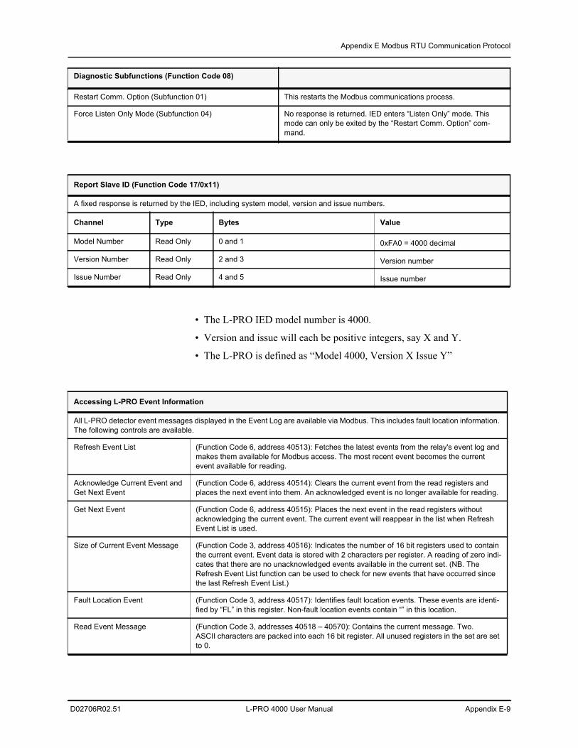
Appendix E Modbus RTU Communication Protocol
D02706R02.51 L-PRO 4000 User Manual Appendix E-9
• The L-PRO IED model number is 4000.
• Version and issue will each be positive integers, say X and Y.
• The L-PRO is defined as “Model 4000, Version X Issue Y”
Restart Comm. Option (Subfunction 01) This restarts the Modbus communications process.
Force Listen Only Mode (Subfunction 04) No response is returned. IED enters “Listen Only” mode. This mode can only be exited by the “Restart Comm. Option” com-mand.
Diagnostic Subfunctions (Function Code 08)
Report Slave ID (Function Code 17/0x11)
A fixed response is returned by the IED, including system model, version and issue numbers.
Channel Type Bytes Value
Model Number Read Only 0 and 1 0xFA0 = 4000 decimal
Version Number Read Only 2 and 3 Version number
Issue Number Read Only 4 and 5 Issue number
Accessing L-PRO Event Information
All L-PRO detector event messages displayed in the Event Log are available via Modbus. This includes fault location information. The following controls are available.
Refresh Event List (Function Code 6, address 40513): Fetches the latest events from the relay's event log and makes them available for Modbus access. The most recent event becomes the current event available for reading.
Acknowledge Current Event and Get Next Event
(Function Code 6, address 40514): Clears the current event from the read registers and places the next event into them. An acknowledged event is no longer available for reading.
Get Next Event (Function Code 6, address 40515): Places the next event in the read registers without acknowledging the current event. The current event will reappear in the list when Refresh Event List is used.
Size of Current Event Message (Function Code 3, address 40516): Indicates the number of 16 bit registers used to contain the current event. Event data is stored with 2 characters per register. A reading of zero indi-cates that there are no unacknowledged events available in the current set. (NB. The Refresh Event List function can be used to check for new events that have occurred since the last Refresh Event List.)
Fault Location Event (Function Code 3, address 40517): Identifies fault location events. These events are identi-fied by “FL” in this register. Non-fault location events contain “” in this location.
Read Event Message (Function Code 3, addresses 40518 – 40570): Contains the current message. Two.ASCII characters are packed into each 16 bit register. All unused registers in the set are set to 0.
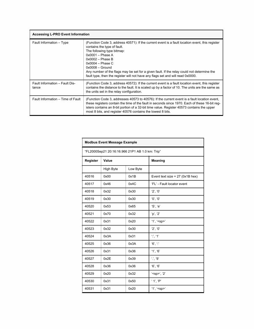
Fault Information – Type (Function Code 3, address 40571): If the current event is a fault location event, this register contains the type of fault. The following type bitmap:0x0001 – Phase A0x0002 – Phase B0x0004 – Phase C0x0008 – GroundAny number of the flags may be set for a given fault. If the relay could not determine the fault type, then the register will not have any flags set and will read 0x0000.
Fault Information – Fault Dis-tance
(Function Code 3, address 40572): If the current event is a fault location event, this register contains the distance to the fault. It is scaled up by a factor of 10. The units are the same as the units set in the relay configuration.
Fault Information – Time of Fault (Function Code 3, addresses 40573 to 40576): If the current event is a fault location event, these registers contain the time of the fault in seconds since 1970. Each of these 16-bit reg-isters contains an 8-bit portion of a 32-bit time value. Register 40573 contains the upper most 8 bits, and register 40576 contains the lowest 8 bits.
Accessing L-PRO Event Information
Modbus Event Message Example
“FL2000Sep21 20:16:16.966 21P1 AB 1.0 km: Trip”
Register Value Meaning
High Byte Low Byte
40516 0x00 0x1B Event text size = 27 (0x1B hex)
40517 0x46 0x4C ‘FL’ - Fault locator event
40518 0x32 0x30 ‘2’, ‘0’
40519 0x30 0x30 ‘0’, ‘0’
40520 0x53 0x65 ‘S’, ‘e’
40521 0x70 0x32 ‘p’, ‘2’
40522 0x31 0x20 ‘1’, ‘<sp>’
40523 0x32 0x30 ‘2’, ‘0’
40524 0x3A 0x31 ‘:’, ‘1’
40525 0x36 0x3A ‘6’, ‘:’
40526 0x31 0x36 ‘1’, ‘6’
40527 0x2E 0x39 ‘.’, ‘9’
40528 0x36 0x36 ‘6’, ‘6’
40529 0x20 0x32 ‘<sp>’, ‘2’
40530 0x31 0x50 ‘ 1’, ‘P’
40531 0x31 0x20 ‘1’, ‘<sp>‘
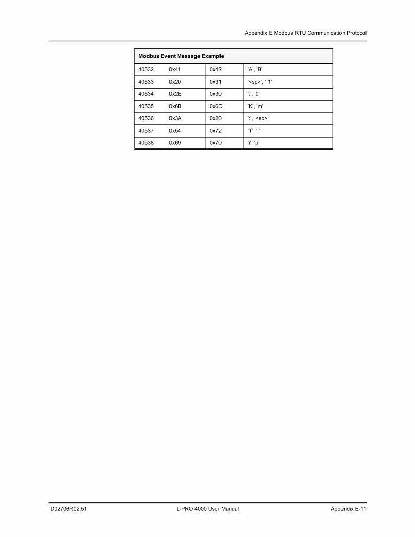
Appendix E Modbus RTU Communication Protocol
D02706R02.51 L-PRO 4000 User Manual Appendix E-11
40532 0x41 0x42 ’A’, ’B’
40533 0x20 0x31 ’<sp>’, ’ 1’
40534 0x2E 0x30 ’.’, ’0’
40535 0x6B 0x6D ’K’, ’m’
40536 0x3A 0x20 ’:’, ’<sp>’
40537 0x54 0x72 ‘T’, ‘r’
40538 0x69 0x70 ‘i’, ‘p’
Modbus Event Message Example

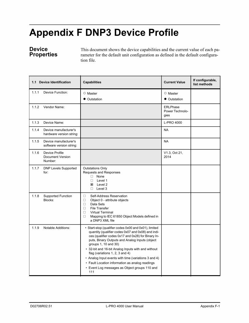
D02706R02.51 L-PRO 4000 User Manual Appendix F-1
Appendix F DNP3 Device ProfileDevice Properties
This document shows the device capabilities and the current value of each pa-rameter for the default unit configuration as defined in the default configura-tion file.
1.1 Device Identification Capabilities Current Value If configurable, list methods
1.1.1 Device Function: ○ Master
● Outstation
○ Master
● Outstation
1.1.2 Vendor Name: ERLPhase Power Technolo-gies
1.1.3 Device Name: L-PRO 4000
1.1.4 Device manufacturer's hardware version string:
NA
1.1.5 Device manufacturer's software version string:
NA
1.1.6 Device Profile Document Version Number:
V1.3, Oct 21, 2014
1.1.7 DNP Levels Supported for:
Outstations OnlyRequests and Responses
None Level 1 Level 2Level 3
1.1.8 Supported Function Blocks:
Self-Address Reservation Object 0 - attribute objects Data Sets File Transfer Virtual Terminal Mapping to IEC 61850 Object Models defined in
a DNP3 XML file
1.1.9 Notable Additions: • Start-stop (qualifier codes 0x00 and 0x01), limited quantity (qualifier codes 0x07 and 0x08) and indi-ces (qualifier codes 0x17 and 0x28) for Binary In-puts, Binary Outputs and Analog Inputs (object groups 1, 10 and 30)
• 32-bit and 16-bit Analog Inputs with and without flag (variations 1, 2, 3 and 4)
• Analog Input events with time (variations 3 and 4) • Fault Location information as analog readings • Event Log messages as Object groups 110 and
111
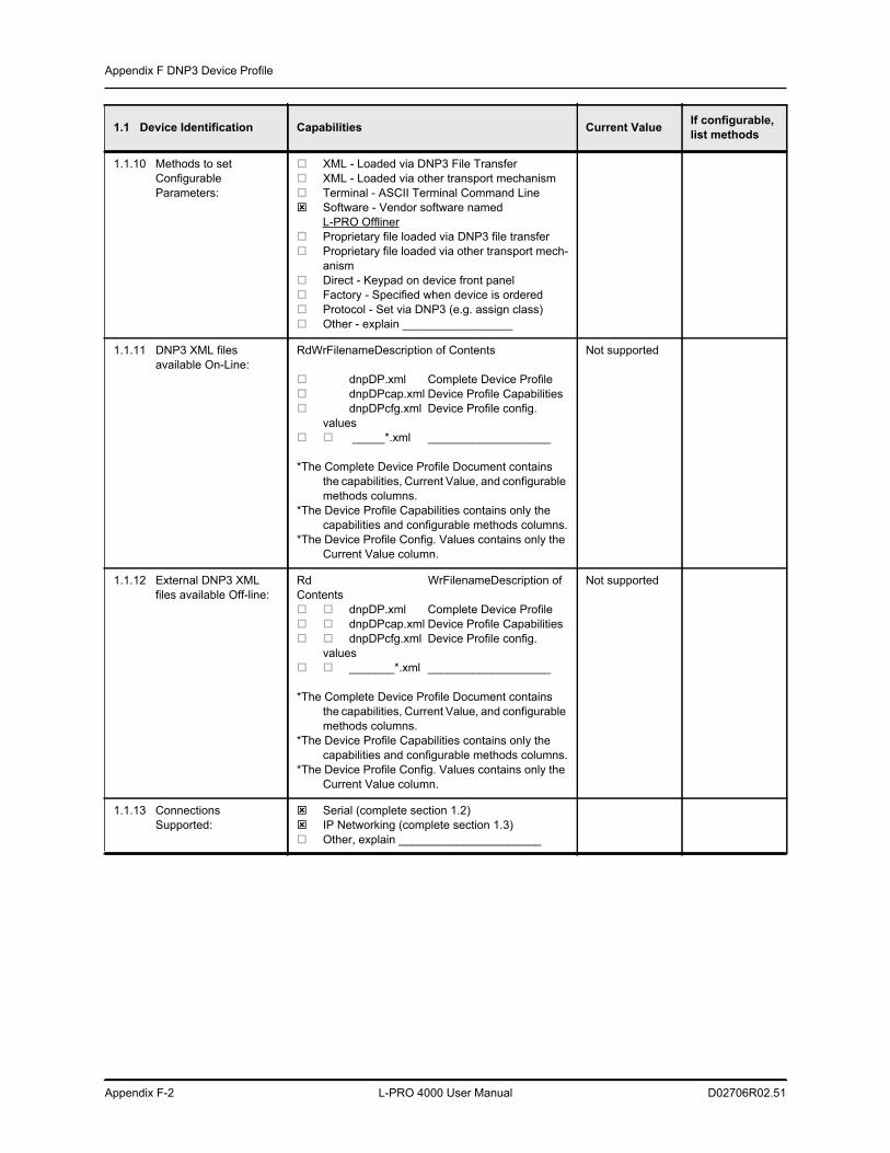
Appendix F DNP3 Device Profile
Appendix F-2 L-PRO 4000 User Manual D02706R02.51
1.1.10 Methods to set Configurable Parameters:
XML - Loaded via DNP3 File Transfer XML - Loaded via other transport mechanism Terminal - ASCII Terminal Command Line Software - Vendor software named
L-PRO Offliner Proprietary file loaded via DNP3 file transfer Proprietary file loaded via other transport mech-
anism Direct - Keypad on device front panel Factory - Specified when device is ordered Protocol - Set via DNP3 (e.g. assign class) Other - explain _________________
1.1.11 DNP3 XML files available On-Line:
RdWrFilenameDescription of Contents
dnpDP.xml Complete Device Profile dnpDPcap.xml Device Profile Capabilities dnpDPcfg.xml Device Profile config.
values _____*.xml ___________________
*The Complete Device Profile Document contains the capabilities, Current Value, and configurable methods columns.
*The Device Profile Capabilities contains only the capabilities and configurable methods columns.
*The Device Profile Config. Values contains only the Current Value column.
Not supported
1.1.12 External DNP3 XML files available Off-line:
Rd WrFilenameDescription of Contents dnpDP.xml Complete Device Profile dnpDPcap.xml Device Profile Capabilities dnpDPcfg.xml Device Profile config.
values _______*.xml ___________________
*The Complete Device Profile Document contains the capabilities, Current Value, and configurable methods columns.
*The Device Profile Capabilities contains only the capabilities and configurable methods columns.
*The Device Profile Config. Values contains only the Current Value column.
Not supported
1.1.13 Connections Supported:
Serial (complete section 1.2) IP Networking (complete section 1.3) Other, explain ______________________
1.1 Device Identification Capabilities Current Value If configurable, list methods
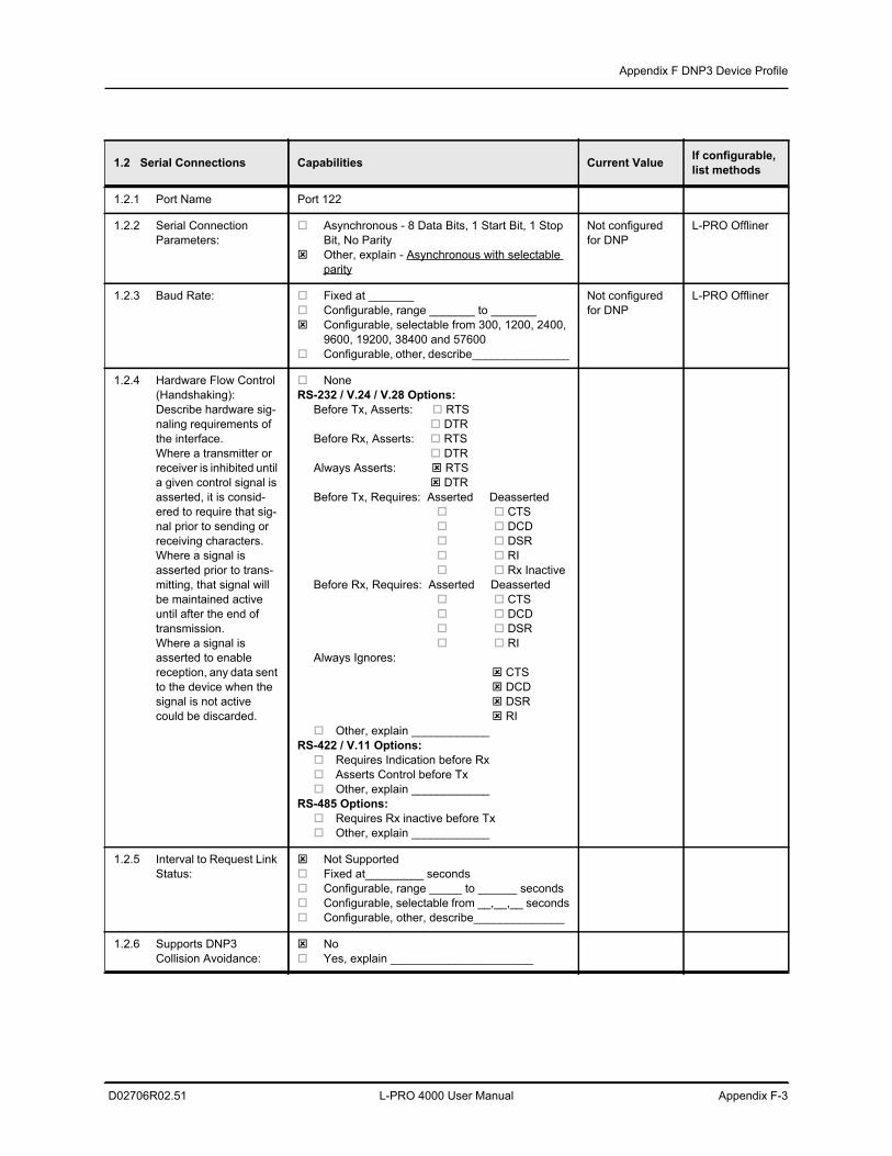
Appendix F DNP3 Device Profile
D02706R02.51 L-PRO 4000 User Manual Appendix F-3
1.2 Serial Connections Capabilities Current Value If configurable, list methods
1.2.1 Port Name Port 122
1.2.2 Serial Connection Parameters:
Asynchronous - 8 Data Bits, 1 Start Bit, 1 Stop Bit, No Parity
Other, explain - Asynchronous with selectable parity
Not configured for DNP
L-PRO Offliner
1.2.3 Baud Rate: Fixed at _______ Configurable, range _______ to _______ Configurable, selectable from 300, 1200, 2400,
9600, 19200, 38400 and 57600 Configurable, other, describe_______________
Not configured for DNP
L-PRO Offliner
1.2.4 Hardware Flow Control (Handshaking):Describe hardware sig-naling requirements of the interface.Where a transmitter or receiver is inhibited until a given control signal is asserted, it is consid-ered to require that sig-nal prior to sending or receiving characters.Where a signal is asserted prior to trans-mitting, that signal will be maintained active until after the end of transmission.Where a signal is asserted to enable reception, any data sent to the device when the signal is not active could be discarded.
NoneRS-232 / V.24 / V.28 Options: Before Tx, Asserts: RTS DTR Before Rx, Asserts: RTS DTR Always Asserts: RTS DTR Before Tx, Requires: Asserted Deasserted CTS DCD DSR RI Rx Inactive Before Rx, Requires: Asserted Deasserted CTS DCD DSR RI Always Ignores: CTS DCD DSR RI Other, explain ____________RS-422 / V.11 Options: Requires Indication before Rx Asserts Control before Tx Other, explain ____________RS-485 Options: Requires Rx inactive before Tx Other, explain ____________
1.2.5 Interval to Request Link Status:
Not Supported Fixed at_________ seconds Configurable, range _____ to ______ seconds Configurable, selectable from __,__,__ seconds Configurable, other, describe______________
1.2.6 Supports DNP3 Collision Avoidance:
No Yes, explain ______________________
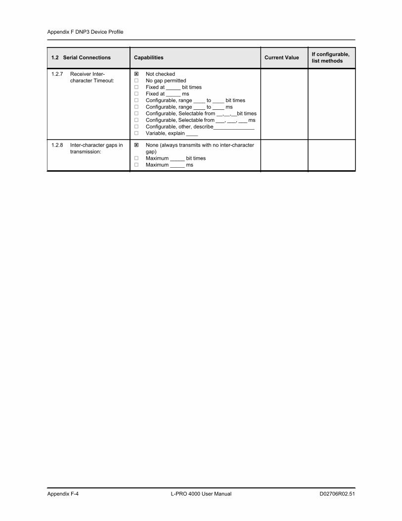
Appendix F DNP3 Device Profile
Appendix F-4 L-PRO 4000 User Manual D02706R02.51
1.2.7 Receiver Inter-character Timeout:
Not checked No gap permitted Fixed at _____ bit times Fixed at _____ ms Configurable, range ____ to ____ bit times Configurable, range ____ to ____ ms Configurable, Selectable from __,__,__bit times Configurable, Selectable from ___, ___, ___ ms Configurable, other, describe______________ Variable, explain ____
1.2.8 Inter-character gaps in transmission:
None (always transmits with no inter-character gap)
Maximum _____ bit times Maximum _____ ms
1.2 Serial Connections Capabilities Current Value If configurable, list methods
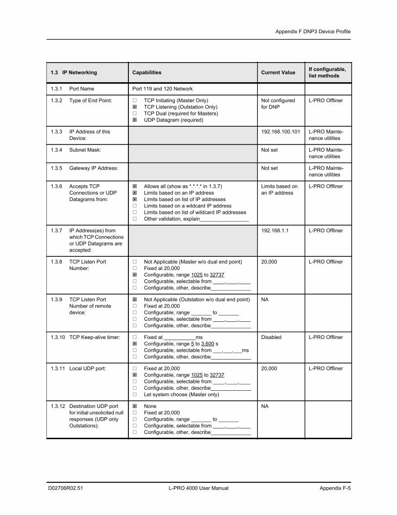
Appendix F DNP3 Device Profile
D02706R02.51 L-PRO 4000 User Manual Appendix F-5
1.3 IP Networking Capabilities Current Value If configurable, list methods
1.3.1 Port Name Port 119 and 120 Network
1.3.2 Type of End Point: TCP Initiating (Master Only) TCP Listening (Outstation Only) TCP Dual (required for Masters) UDP Datagram (required)
Not configured for DNP
L-PRO Offliner
1.3.3 IP Address of this Device:
192.168.100.101 L-PRO Mainte-nance utilities
1.3.4 Subnet Mask: Not set L-PRO Mainte-nance utilities
1.3.5 Gateway IP Address: Not set L-PRO Mainte-nance utilities
1.3.6 Accepts TCP Connections or UDP Datagrams from:
Allows all (show as *.*.*.* in 1.3.7) Limits based on an IP address Limits based on list of IP addresses Limits based on a wildcard IP address Limits based on list of wildcard IP addresses Other validation, explain_________________
Limits based on an IP address
L-PRO Offliner
1.3.7 IP Address(es) from which TCP Connections or UDP Datagrams are accepted:
192.168.1.1 L-PRO Offliner
1.3.8 TCP Listen Port Number:
Not Applicable (Master w/o dual end point) Fixed at 20,000 Configurable, range 1025 to 32737 Configurable, selectable from ____,____,____ Configurable, other, describe______________
20,000 L-PRO Offliner
1.3.9 TCP Listen Port Number of remote device:
Not Applicable (Outstation w/o dual end point) Fixed at 20,000 Configurable, range _______ to _______ Configurable, selectable from ____,____,____ Configurable, other, describe______________
NA
1.3.10 TCP Keep-alive timer: Fixed at ___________ms Configurable, range 5 to 3,600 s Configurable, selectable from ___,___,___ms Configurable, other, describe______________
Disabled L-PRO Offliner
1.3.11 Local UDP port: Fixed at 20,000 Configurable, range 1025 to 32737 Configurable, selectable from ____,____,____ Configurable, other, describe______________ Let system choose (Master only)
20,000 L-PRO Offliner
1.3.12 Destination UDP port for initial unsolicited null responses (UDP only Outstations):
None Fixed at 20,000 Configurable, range _______ to _______ Configurable, selectable from ____,____,____ Configurable, other, describe______________
NA
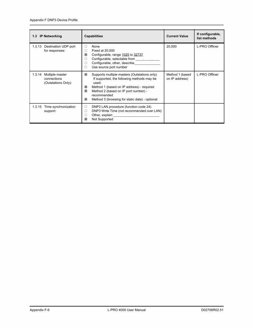
Appendix F DNP3 Device Profile
Appendix F-6 L-PRO 4000 User Manual D02706R02.51
1.3.13 Destination UDP port for responses:
None Fixed at 20,000 Configurable, range 1025 to 32737 Configurable, selectable from ____,____,____ Configurable, other, describe______________ Use source port number
20,000 L-PRO Offliner
1.3.14 Multiple master connections (Outstations Only):
Supports multiple masters (Outstations only)If supported, the following methods may be used:
Method 1 (based on IP address) - required Method 2 (based on IP port number) -
recommended Method 3 (browsing for static data) - optional
Method 1 (based on IP address)
L-PRO Offliner
1.3.15 Time synchronization support:
DNP3 LAN procedure (function code 24) DNP3 Write Time (not recommended over LAN) Other, explain _________________________ Not Supported
1.3 IP Networking Capabilities Current Value If configurable, list methods
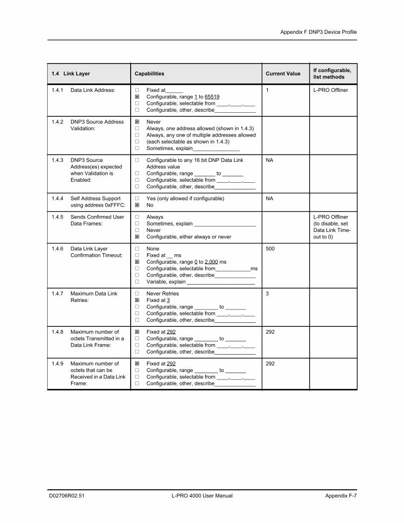
Appendix F DNP3 Device Profile
D02706R02.51 L-PRO 4000 User Manual Appendix F-7
1.4 Link Layer Capabilities Current Value If configurable, list methods
1.4.1 Data Link Address: Fixed at______ Configurable, range 1 to 65519 Configurable, selectable from ____,____,____ Configurable, other, describe______________
1 L-PRO Offliner
1.4.2 DNP3 Source Address Validation:
Never Always, one address allowed (shown in 1.4.3) Always, any one of multiple addresses allowed (each selectable as shown in 1.4.3) Sometimes, explain________________
1.4.3 DNP3 Source Address(es) expected when Validation is Enabled:
Configurable to any 16 bit DNP Data Link Address value
Configurable, range _______ to _______ Configurable, selectable from ____,____,____ Configurable, other, describe______________
NA
1.4.4 Self Address Support using address 0xFFFC:
Yes (only allowed if configurable) No
NA
1.4.5 Sends Confirmed User Data Frames:
Always Sometimes, explain _____________________ Never Configurable, either always or never
L-PRO Offliner(to disable, set Data Link Time-out to 0)
1.4.6 Data Link Layer Confirmation Timeout:
None Fixed at __ ms Configurable, range 0 to 2,000 ms Configurable, selectable from____________ms Configurable, other, describe______________ Variable, explain _______________________
500
1.4.7 Maximum Data Link Retries:
Never Retries Fixed at 3 Configurable, range ________ to _______ Configurable, selectable from ____,____,____ Configurable, other, describe______________
3
1.4.8 Maximum number of octets Transmitted in a Data Link Frame:
Fixed at 292 Configurable, range ________ to _______ Configurable, selectable from ____,____,____ Configurable, other, describe______________
292
1.4.9 Maximum number of octets that can be Received in a Data Link Frame:
Fixed at 292 Configurable, range ________ to _______ Configurable, selectable from ____,____,____ Configurable, other, describe______________
292
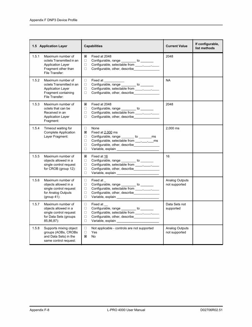
Appendix F DNP3 Device Profile
Appendix F-8 L-PRO 4000 User Manual D02706R02.51
1.5 Application Layer Capabilities Current Value If configurable, list methods
1.5.1 Maximum number of octets Transmitted in an Application Layer Fragment other than File Transfer:
Fixed at 2048 Configurable, range ________ to _______ Configurable, selectable from ____,____,____ Configurable, other, describe______________
2048
1.5.2 Maximum number of octets Transmitted in an Application Layer Fragment containing File Transfer:
Fixed at ___________ Configurable, range ________ to _______ Configurable, selectable from ____,____,____ Configurable, other, describe______________
NA
1.5.3 Maximum number of octets that can be Received in an Application Layer Fragment:
Fixed at 2048 Configurable, range ________ to _______ Configurable, selectable from ____,____,____ Configurable, other, describe______________
2048
1.5.4 Timeout waiting for Complete Application Layer Fragment:
None Fixed at 2,000 ms Configurable, range _______ to _______ms Configurable, selectable from ___,___,___ms Configurable, other, describe______________ Variable, explain _______________________
2,000 ms
1.5.5 Maximum number of objects allowed in a single control request for CROB (group 12):
Fixed at 16 Configurable, range ________ to _______ Configurable, selectable from ____,____,____ Configurable, other, describe______________ Variable, explain _______________________
16
1.5.6 Maximum number of objects allowed in a single control request for Analog Outputs (group 41):
Fixed at _ Configurable, range ________ to _______ Configurable, selectable from ____,____,____ Configurable, other, describe______________ Variable, explain _______________________
Analog Outputs not supported
1.5.7 Maximum number of objects allowed in a single control request for Data Sets (groups 85,86,87):
Fixed at __ Configurable, range ________ to _______ Configurable, selectable from ____,____,____ Configurable, other, describe______________ Variable, explain _______________________
Data Sets not supported
1.5.8 Supports mixing object groups (AOBs, CROBs and Data Sets) in the same control request:
Not applicable - controls are not supported Yes No
Analog Outputs not supported
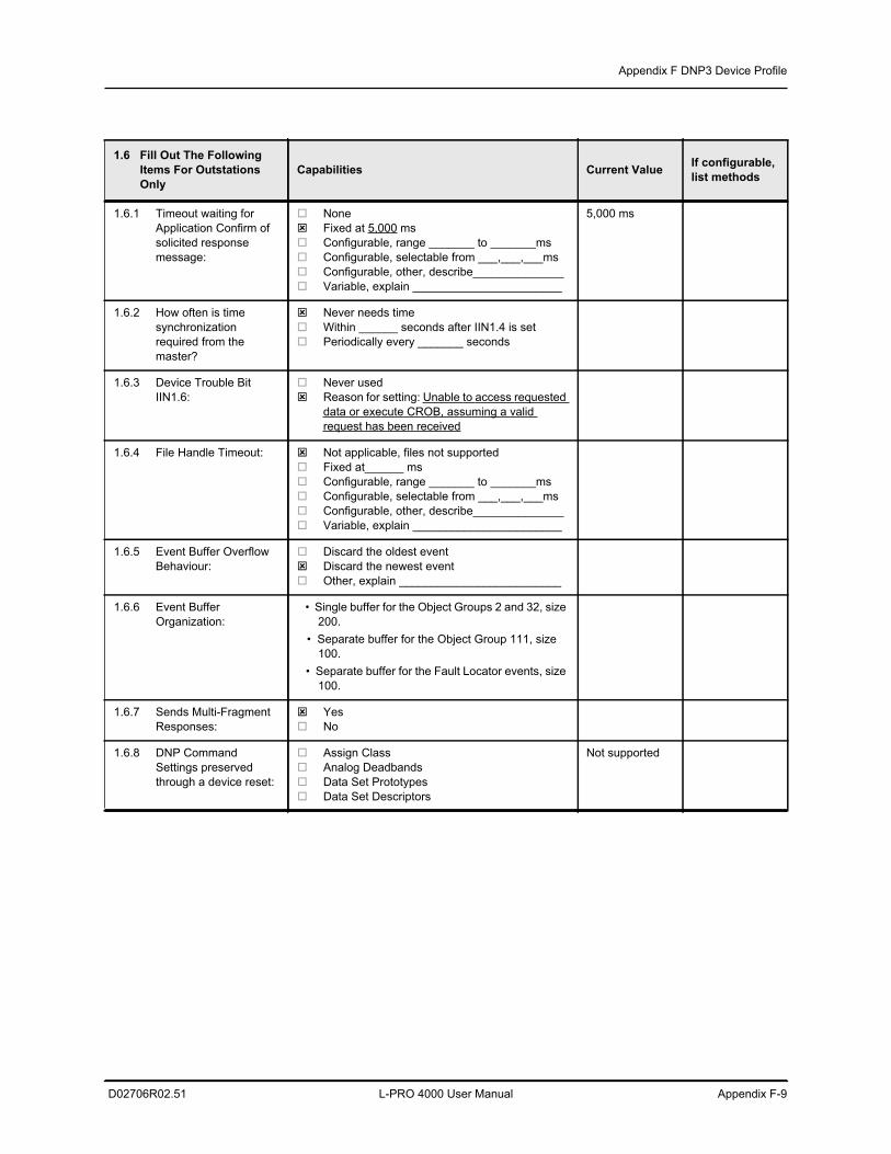
Appendix F DNP3 Device Profile
D02706R02.51 L-PRO 4000 User Manual Appendix F-9
1.6 Fill Out The Following Items For Outstations Only
Capabilities Current Value If configurable, list methods
1.6.1 Timeout waiting for Application Confirm of solicited response message:
None Fixed at 5,000 ms Configurable, range _______ to _______ms Configurable, selectable from ___,___,___ms Configurable, other, describe______________ Variable, explain _______________________
5,000 ms
1.6.2 How often is time synchronization required from the master?
Never needs time Within ______ seconds after IIN1.4 is set Periodically every _______ seconds
1.6.3 Device Trouble Bit IIN1.6:
Never used Reason for setting: Unable to access requested
data or execute CROB, assuming a valid request has been received
1.6.4 File Handle Timeout: Not applicable, files not supported Fixed at______ ms Configurable, range _______ to _______ms Configurable, selectable from ___,___,___ms Configurable, other, describe______________ Variable, explain _______________________
1.6.5 Event Buffer Overflow Behaviour:
Discard the oldest event Discard the newest event Other, explain _________________________
1.6.6 Event Buffer Organization:
• Single buffer for the Object Groups 2 and 32, size 200.
• Separate buffer for the Object Group 111, size 100.
• Separate buffer for the Fault Locator events, size 100.
1.6.7 Sends Multi-Fragment Responses:
Yes No
1.6.8 DNP Command Settings preserved through a device reset:
Assign Class Analog Deadbands Data Set Prototypes Data Set Descriptors
Not supported
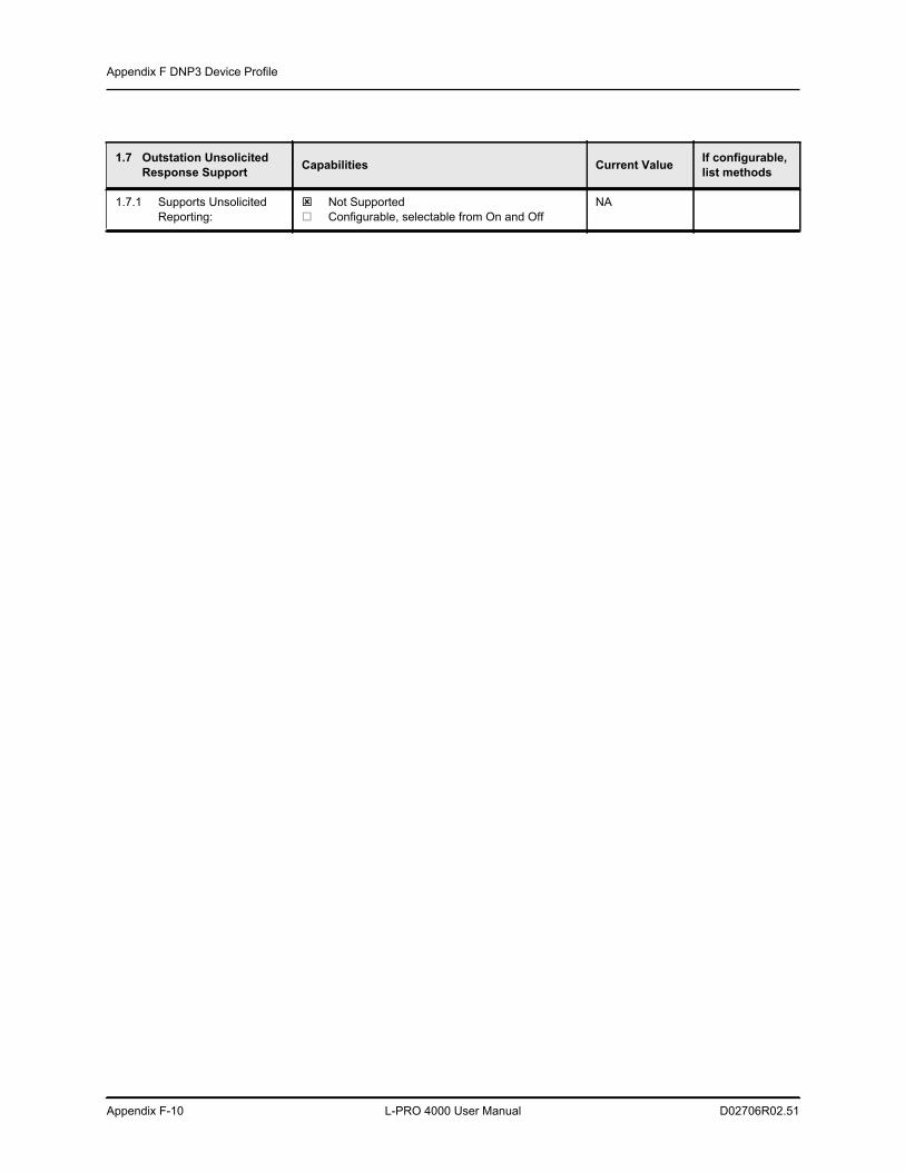
Appendix F DNP3 Device Profile
Appendix F-10 L-PRO 4000 User Manual D02706R02.51
1.7 Outstation Unsolicited Response Support Capabilities Current Value If configurable,
list methods
1.7.1 Supports Unsolicited Reporting:
Not Supported Configurable, selectable from On and Off
NA
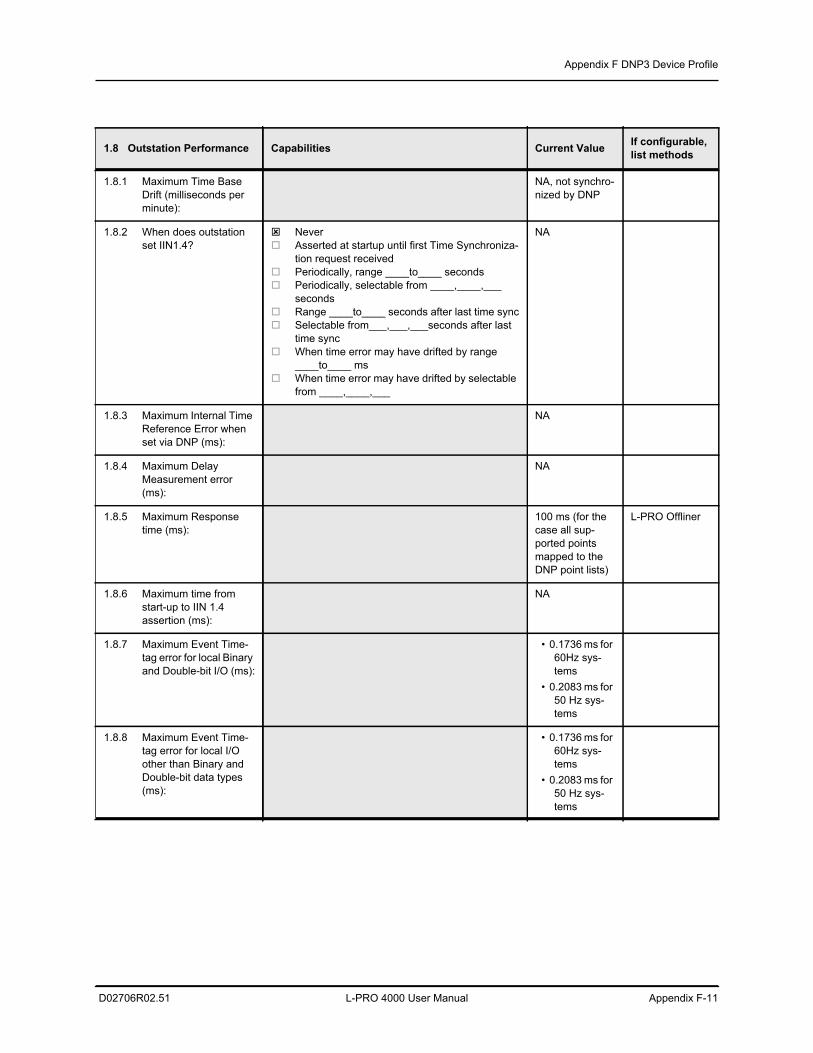
Appendix F DNP3 Device Profile
D02706R02.51 L-PRO 4000 User Manual Appendix F-11
1.8 Outstation Performance Capabilities Current Value If configurable, list methods
1.8.1 Maximum Time Base Drift (milliseconds per minute):
NA, not synchro-nized by DNP
1.8.2 When does outstation set IIN1.4?
Never Asserted at startup until first Time Synchroniza-
tion request received Periodically, range ____to____ seconds Periodically, selectable from ____,____,___
seconds Range ____to____ seconds after last time sync Selectable from___,___,___seconds after last
time sync When time error may have drifted by range
____to____ ms When time error may have drifted by selectable
from ____,____,___
NA
1.8.3 Maximum Internal Time Reference Error when set via DNP (ms):
NA
1.8.4 Maximum Delay Measurement error (ms):
NA
1.8.5 Maximum Response time (ms):
100 ms (for the case all sup-ported points mapped to the DNP point lists)
L-PRO Offliner
1.8.6 Maximum time from start-up to IIN 1.4 assertion (ms):
NA
1.8.7 Maximum Event Time-tag error for local Binary and Double-bit I/O (ms):
• 0.1736 ms for 60Hz sys-tems
• 0.2083 ms for 50 Hz sys-tems
1.8.8 Maximum Event Time-tag error for local I/O other than Binary and Double-bit data types (ms):
• 0.1736 ms for 60Hz sys-tems
• 0.2083 ms for 50 Hz sys-tems
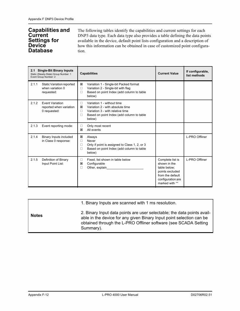
Appendix F DNP3 Device Profile
Appendix F-12 L-PRO 4000 User Manual D02706R02.51
Capabilities and Current Settings for Device Database
The following tables identify the capabilities and current settings for each DNP3 data type. Each data type also provides a table defining the data points available in the device, default point lists configuration and a description of how this information can be obtained in case of customized point configura-tion.
2.1 Single-Bit Binary InputsStatic (Steady-State) Group Number: 1Event Group Number: 2
Capabilities Current Value If configurable, list methods
2.1.1 Static Variation reported when variation 0 requested:
Variation 1 - Single-bit Packed format Variation 2 - Single-bit with flag Based on point Index (add column to table
below)
2.1.2 Event Variation reported when variation 0 requested:
Variation 1 - without time Variation 2 - with absolute time Variation 3 - with relative time Based on point Index (add column to table
below)
2.1.3 Event reporting mode: Only most recent All events
2.1.4 Binary Inputs included in Class 0 response:
Always Never Only if point is assigned to Class 1, 2, or 3 Based on point Index (add column to table
below)
L-PRO Offliner
2.1.5 Definition of Binary Input Point List:
Fixed, list shown in table below Configurable Other, explain_____________________
Complete list is shown in the table below; points excluded from the default configuration are marked with ‘*’
L-PRO Offliner
Notes
1. Binary Inputs are scanned with 1 ms resolution.
2. Binary Input data points are user selectable; the data points avail-able in the device for any given Binary Input point selection can be obtained through the L-PRO Offliner software (see SCADA Setting Summary).
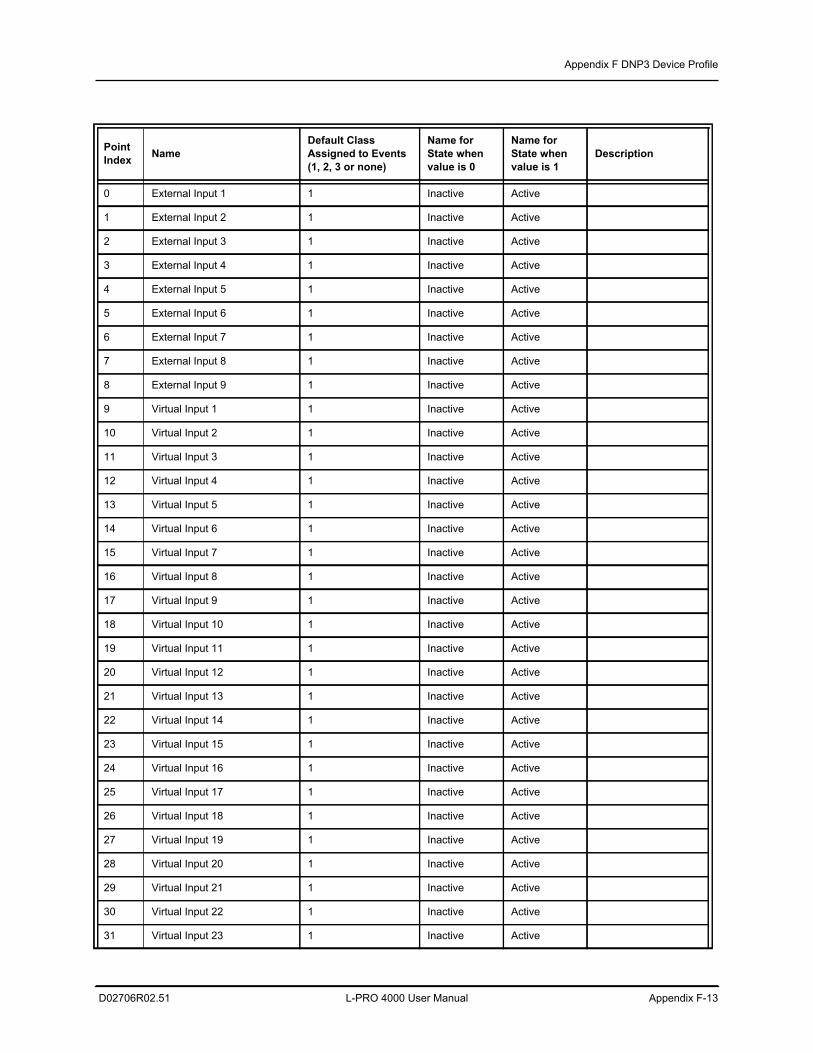
Appendix F DNP3 Device Profile
D02706R02.51 L-PRO 4000 User Manual Appendix F-13
Point Index Name
Default ClassAssigned to Events(1, 2, 3 or none)
Name for State when value is 0
Name for State when value is 1
Description
0 External Input 1 1 Inactive Active
1 External Input 2 1 Inactive Active
2 External Input 3 1 Inactive Active
3 External Input 4 1 Inactive Active
4 External Input 5 1 Inactive Active
5 External Input 6 1 Inactive Active
6 External Input 7 1 Inactive Active
7 External Input 8 1 Inactive Active
8 External Input 9 1 Inactive Active
9 Virtual Input 1 1 Inactive Active
10 Virtual Input 2 1 Inactive Active
11 Virtual Input 3 1 Inactive Active
12 Virtual Input 4 1 Inactive Active
13 Virtual Input 5 1 Inactive Active
14 Virtual Input 6 1 Inactive Active
15 Virtual Input 7 1 Inactive Active
16 Virtual Input 8 1 Inactive Active
17 Virtual Input 9 1 Inactive Active
18 Virtual Input 10 1 Inactive Active
19 Virtual Input 11 1 Inactive Active
20 Virtual Input 12 1 Inactive Active
21 Virtual Input 13 1 Inactive Active
22 Virtual Input 14 1 Inactive Active
23 Virtual Input 15 1 Inactive Active
24 Virtual Input 16 1 Inactive Active
25 Virtual Input 17 1 Inactive Active
26 Virtual Input 18 1 Inactive Active
27 Virtual Input 19 1 Inactive Active
28 Virtual Input 20 1 Inactive Active
29 Virtual Input 21 1 Inactive Active
30 Virtual Input 22 1 Inactive Active
31 Virtual Input 23 1 Inactive Active
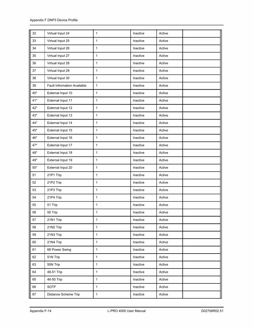
Appendix F DNP3 Device Profile
Appendix F-14 L-PRO 4000 User Manual D02706R02.51
32 Virtual Input 24 1 Inactive Active
33 Virtual Input 25 1 Inactive Active
34 Virtual Input 26 1 Inactive Active
35 Virtual Input 27 1 Inactive Active
36 Virtual Input 28 1 Inactive Active
37 Virtual Input 29 1 Inactive Active
38 Virtual Input 30 1 Inactive Active
39 Fault Information Available 1 Inactive Active
40* External Input 10 1 Inactive Active
41* External Input 11 1 Inactive Active
42* External Input 12 1 Inactive Active
43* External Input 13 1 Inactive Active
44* External Input 14 1 Inactive Active
45* External Input 15 1 Inactive Active
46* External Input 16 1 Inactive Active
47* External Input 17 1 Inactive Active
48* External Input 18 1 Inactive Active
49* External Input 19 1 Inactive Active
50* External Input 20 1 Inactive Active
51 21P1 Trip 1 Inactive Active
52 21P2 Trip 1 Inactive Active
53 21P3 Trip 1 Inactive Active
54 21P4 Trip 1 Inactive Active
55 51 Trip 1 Inactive Active
56 50 Trip 1 Inactive Active
57 21N1 Trip 1 Inactive Active
58 21N2 Trip 1 Inactive Active
59 21N3 Trip 1 Inactive Active
60 21N4 Trip 1 Inactive Active
61 68 Power Swing 1 Inactive Active
62 51N Trip 1 Inactive Active
63 50N Trip 1 Inactive Active
64 46-51 Trip 1 Inactive Active
65 46-50 Trip 1 Inactive Active
66 SOTF 1 Inactive Active
67 Distance Scheme Trip 1 Inactive Active
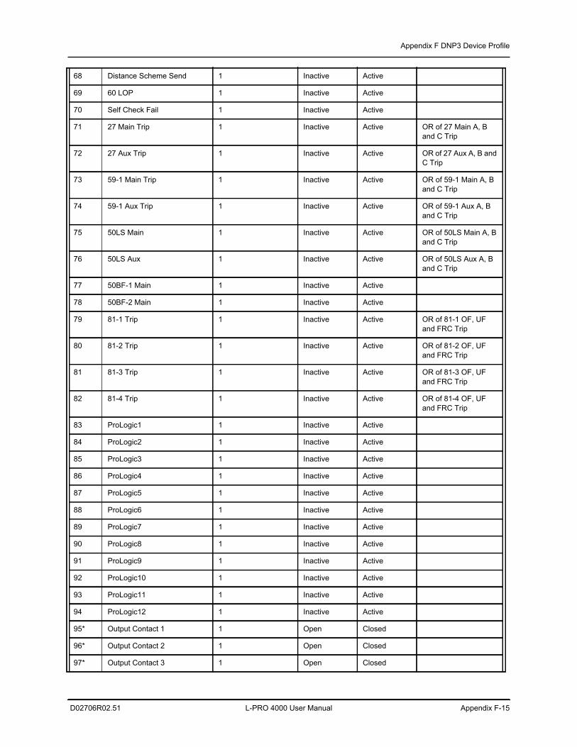
Appendix F DNP3 Device Profile
D02706R02.51 L-PRO 4000 User Manual Appendix F-15
68 Distance Scheme Send 1 Inactive Active
69 60 LOP 1 Inactive Active
70 Self Check Fail 1 Inactive Active
71 27 Main Trip 1 Inactive Active OR of 27 Main A, B and C Trip
72 27 Aux Trip 1 Inactive Active OR of 27 Aux A, B and C Trip
73 59-1 Main Trip 1 Inactive Active OR of 59-1 Main A, B and C Trip
74 59-1 Aux Trip 1 Inactive Active OR of 59-1 Aux A, B and C Trip
75 50LS Main 1 Inactive Active OR of 50LS Main A, B and C Trip
76 50LS Aux 1 Inactive Active OR of 50LS Aux A, B and C Trip
77 50BF-1 Main 1 Inactive Active
78 50BF-2 Main 1 Inactive Active
79 81-1 Trip 1 Inactive Active OR of 81-1 OF, UF and FRC Trip
80 81-2 Trip 1 Inactive Active OR of 81-2 OF, UF and FRC Trip
81 81-3 Trip 1 Inactive Active OR of 81-3 OF, UF and FRC Trip
82 81-4 Trip 1 Inactive Active OR of 81-4 OF, UF and FRC Trip
83 ProLogic1 1 Inactive Active
84 ProLogic2 1 Inactive Active
85 ProLogic3 1 Inactive Active
86 ProLogic4 1 Inactive Active
87 ProLogic5 1 Inactive Active
88 ProLogic6 1 Inactive Active
89 ProLogic7 1 Inactive Active
90 ProLogic8 1 Inactive Active
91 ProLogic9 1 Inactive Active
92 ProLogic10 1 Inactive Active
93 ProLogic11 1 Inactive Active
94 ProLogic12 1 Inactive Active
95* Output Contact 1 1 Open Closed
96* Output Contact 2 1 Open Closed
97* Output Contact 3 1 Open Closed
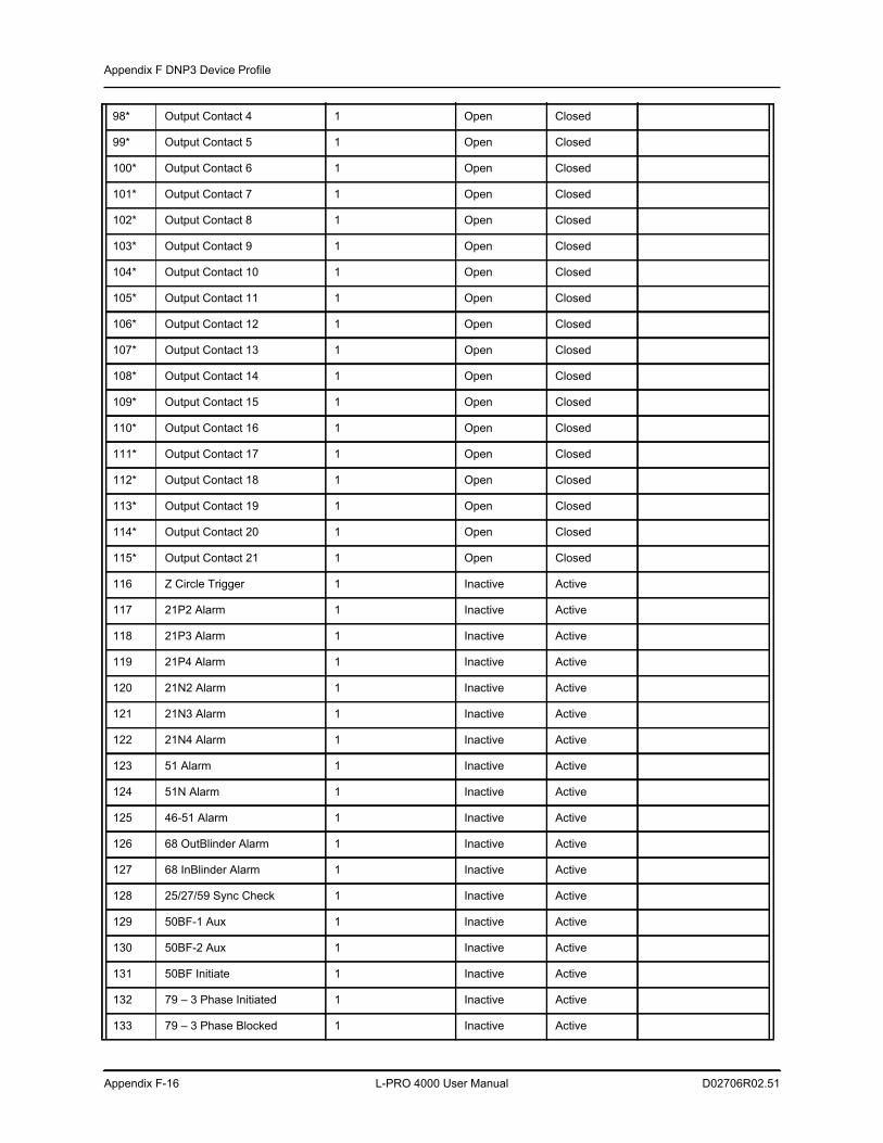
Appendix F DNP3 Device Profile
Appendix F-16 L-PRO 4000 User Manual D02706R02.51
98* Output Contact 4 1 Open Closed
99* Output Contact 5 1 Open Closed
100* Output Contact 6 1 Open Closed
101* Output Contact 7 1 Open Closed
102* Output Contact 8 1 Open Closed
103* Output Contact 9 1 Open Closed
104* Output Contact 10 1 Open Closed
105* Output Contact 11 1 Open Closed
106* Output Contact 12 1 Open Closed
107* Output Contact 13 1 Open Closed
108* Output Contact 14 1 Open Closed
109* Output Contact 15 1 Open Closed
110* Output Contact 16 1 Open Closed
111* Output Contact 17 1 Open Closed
112* Output Contact 18 1 Open Closed
113* Output Contact 19 1 Open Closed
114* Output Contact 20 1 Open Closed
115* Output Contact 21 1 Open Closed
116 Z Circle Trigger 1 Inactive Active
117 21P2 Alarm 1 Inactive Active
118 21P3 Alarm 1 Inactive Active
119 21P4 Alarm 1 Inactive Active
120 21N2 Alarm 1 Inactive Active
121 21N3 Alarm 1 Inactive Active
122 21N4 Alarm 1 Inactive Active
123 51 Alarm 1 Inactive Active
124 51N Alarm 1 Inactive Active
125 46-51 Alarm 1 Inactive Active
126 68 OutBlinder Alarm 1 Inactive Active
127 68 InBlinder Alarm 1 Inactive Active
128 25/27/59 Sync Check 1 Inactive Active
129 50BF-1 Aux 1 Inactive Active
130 50BF-2 Aux 1 Inactive Active
131 50BF Initiate 1 Inactive Active
132 79 – 3 Phase Initiated 1 Inactive Active
133 79 – 3 Phase Blocked 1 Inactive Active
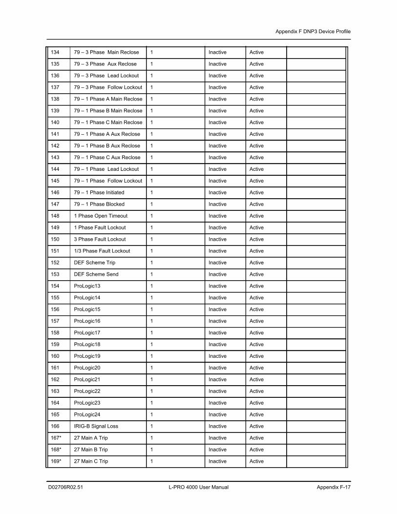
Appendix F DNP3 Device Profile
D02706R02.51 L-PRO 4000 User Manual Appendix F-17
134 79 – 3 Phase Main Reclose 1 Inactive Active
135 79 – 3 Phase Aux Reclose 1 Inactive Active
136 79 – 3 Phase Lead Lockout 1 Inactive Active
137 79 – 3 Phase Follow Lockout 1 Inactive Active
138 79 – 1 Phase A Main Reclose 1 Inactive Active
139 79 – 1 Phase B Main Reclose 1 Inactive Active
140 79 – 1 Phase C Main Reclose 1 Inactive Active
141 79 – 1 Phase A Aux Reclose 1 Inactive Active
142 79 – 1 Phase B Aux Reclose 1 Inactive Active
143 79 – 1 Phase C Aux Reclose 1 Inactive Active
144 79 – 1 Phase Lead Lockout 1 Inactive Active
145 79 – 1 Phase Follow Lockout 1 Inactive Active
146 79 – 1 Phase Initiated 1 Inactive Active
147 79 – 1 Phase Blocked 1 Inactive Active
148 1 Phase Open Timeout 1 Inactive Active
149 1 Phase Fault Lockout 1 Inactive Active
150 3 Phase Fault Lockout 1 Inactive Active
151 1/3 Phase Fault Lockout 1 Inactive Active
152 DEF Scheme Trip 1 Inactive Active
153 DEF Scheme Send 1 Inactive Active
154 ProLogic13 1 Inactive Active
155 ProLogic14 1 Inactive Active
156 ProLogic15 1 Inactive Active
157 ProLogic16 1 Inactive Active
158 ProLogic17 1 Inactive Active
159 ProLogic18 1 Inactive Active
160 ProLogic19 1 Inactive Active
161 ProLogic20 1 Inactive Active
162 ProLogic21 1 Inactive Active
163 ProLogic22 1 Inactive Active
164 ProLogic23 1 Inactive Active
165 ProLogic24 1 Inactive Active
166 IRIG-B Signal Loss 1 Inactive Active
167* 27 Main A Trip 1 Inactive Active
168* 27 Main B Trip 1 Inactive Active
169* 27 Main C Trip 1 Inactive Active
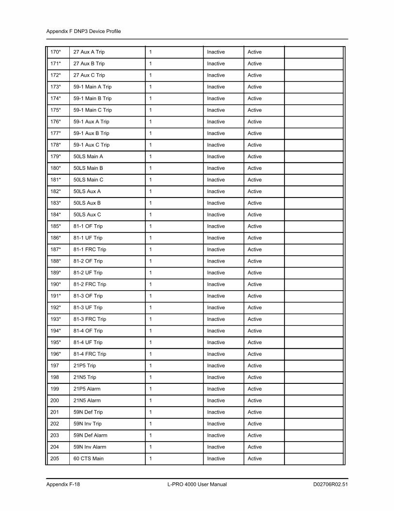
Appendix F DNP3 Device Profile
Appendix F-18 L-PRO 4000 User Manual D02706R02.51
170* 27 Aux A Trip 1 Inactive Active
171* 27 Aux B Trip 1 Inactive Active
172* 27 Aux C Trip 1 Inactive Active
173* 59-1 Main A Trip 1 Inactive Active
174* 59-1 Main B Trip 1 Inactive Active
175* 59-1 Main C Trip 1 Inactive Active
176* 59-1 Aux A Trip 1 Inactive Active
177* 59-1 Aux B Trip 1 Inactive Active
178* 59-1 Aux C Trip 1 Inactive Active
179* 50LS Main A 1 Inactive Active
180* 50LS Main B 1 Inactive Active
181* 50LS Main C 1 Inactive Active
182* 50LS Aux A 1 Inactive Active
183* 50LS Aux B 1 Inactive Active
184* 50LS Aux C 1 Inactive Active
185* 81-1 OF Trip 1 Inactive Active
186* 81-1 UF Trip 1 Inactive Active
187* 81-1 FRC Trip 1 Inactive Active
188* 81-2 OF Trip 1 Inactive Active
189* 81-2 UF Trip 1 Inactive Active
190* 81-2 FRC Trip 1 Inactive Active
191* 81-3 OF Trip 1 Inactive Active
192* 81-3 UF Trip 1 Inactive Active
193* 81-3 FRC Trip 1 Inactive Active
194* 81-4 OF Trip 1 Inactive Active
195* 81-4 UF Trip 1 Inactive Active
196* 81-4 FRC Trip 1 Inactive Active
197 21P5 Trip 1 Inactive Active
198 21N5 Trip 1 Inactive Active
199 21P5 Alarm 1 Inactive Active
200 21N5 Alarm 1 Inactive Active
201 59N Def Trip 1 Inactive Active
202 59N Inv Trip 1 Inactive Active
203 59N Def Alarm 1 Inactive Active
204 59N Inv Alarm 1 Inactive Active
205 60 CTS Main 1 Inactive Active
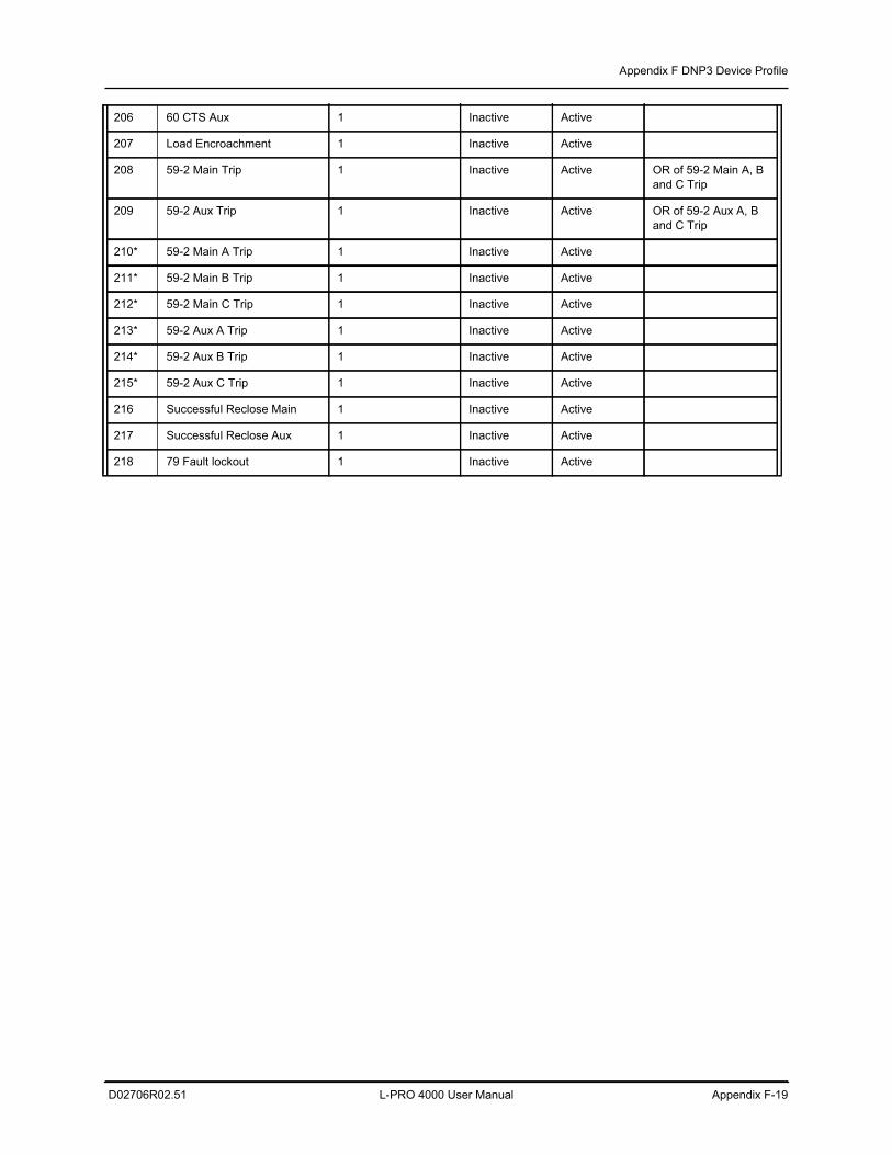
Appendix F DNP3 Device Profile
D02706R02.51 L-PRO 4000 User Manual Appendix F-19
206 60 CTS Aux 1 Inactive Active
207 Load Encroachment 1 Inactive Active
208 59-2 Main Trip 1 Inactive Active OR of 59-2 Main A, B and C Trip
209 59-2 Aux Trip 1 Inactive Active OR of 59-2 Aux A, B and C Trip
210* 59-2 Main A Trip 1 Inactive Active
211* 59-2 Main B Trip 1 Inactive Active
212* 59-2 Main C Trip 1 Inactive Active
213* 59-2 Aux A Trip 1 Inactive Active
214* 59-2 Aux B Trip 1 Inactive Active
215* 59-2 Aux C Trip 1 Inactive Active
216 Successful Reclose Main 1 Inactive Active
217 Successful Reclose Aux 1 Inactive Active
218 79 Fault lockout 1 Inactive Active
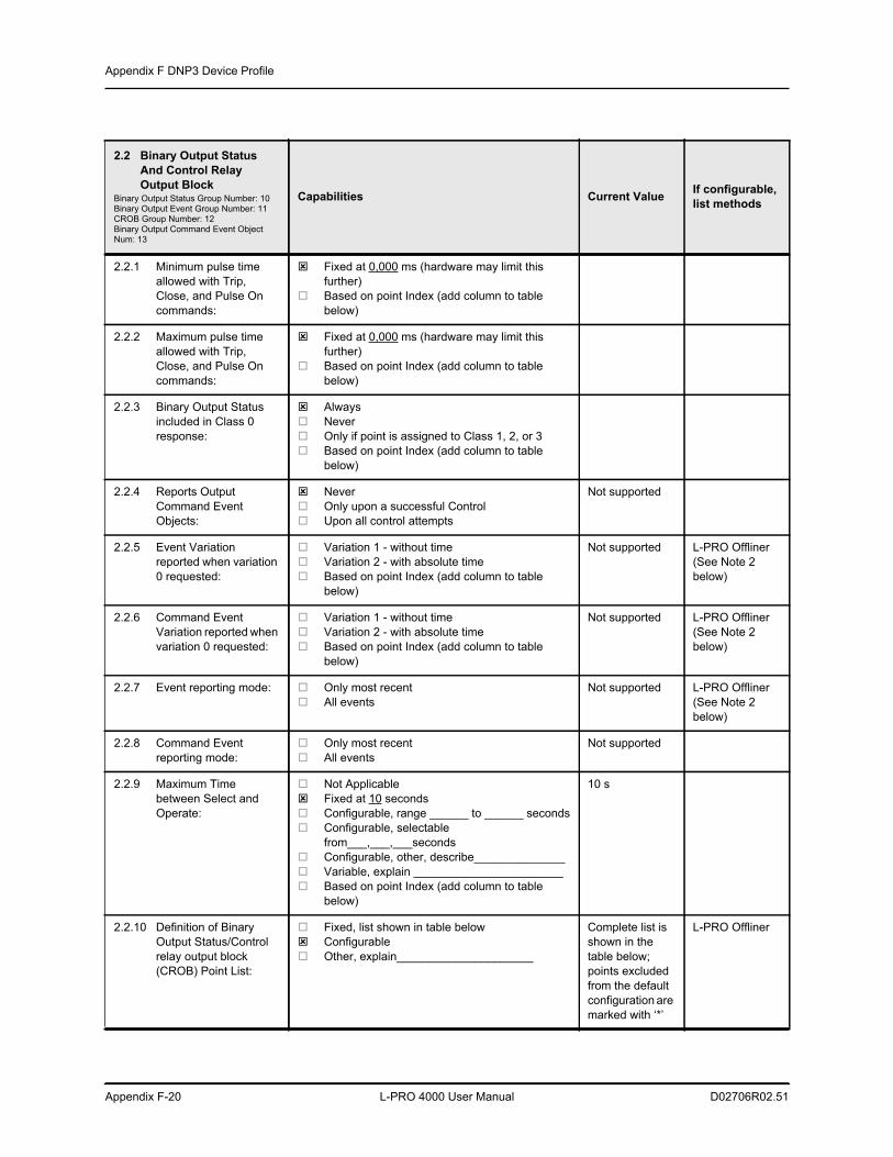
Appendix F DNP3 Device Profile
Appendix F-20 L-PRO 4000 User Manual D02706R02.51
2.2 Binary Output Status And Control Relay Output Block
Binary Output Status Group Number: 10Binary Output Event Group Number: 11CROB Group Number: 12Binary Output Command Event Object Num: 13
Capabilities Current Value If configurable, list methods
2.2.1 Minimum pulse time allowed with Trip, Close, and Pulse On commands:
Fixed at 0,000 ms (hardware may limit this further)
Based on point Index (add column to table below)
2.2.2 Maximum pulse time allowed with Trip, Close, and Pulse On commands:
Fixed at 0,000 ms (hardware may limit this further)
Based on point Index (add column to table below)
2.2.3 Binary Output Status included in Class 0 response:
Always Never Only if point is assigned to Class 1, 2, or 3 Based on point Index (add column to table
below)
2.2.4 Reports Output Command Event Objects:
Never Only upon a successful Control Upon all control attempts
Not supported
2.2.5 Event Variation reported when variation 0 requested:
Variation 1 - without time Variation 2 - with absolute time Based on point Index (add column to table
below)
Not supported L-PRO Offliner(See Note 2 below)
2.2.6 Command Event Variation reported when variation 0 requested:
Variation 1 - without time Variation 2 - with absolute time Based on point Index (add column to table
below)
Not supported L-PRO Offliner(See Note 2 below)
2.2.7 Event reporting mode: Only most recent All events
Not supported L-PRO Offliner(See Note 2 below)
2.2.8 Command Event reporting mode:
Only most recent All events
Not supported
2.2.9 Maximum Time between Select and Operate:
Not Applicable Fixed at 10 seconds Configurable, range ______ to ______ seconds Configurable, selectable
from___,___,___seconds Configurable, other, describe______________ Variable, explain _______________________ Based on point Index (add column to table
below)
10 s
2.2.10 Definition of Binary Output Status/Control relay output block (CROB) Point List:
Fixed, list shown in table below Configurable Other, explain_____________________
Complete list is shown in the table below; points excluded from the default configuration are marked with ‘*’
L-PRO Offliner
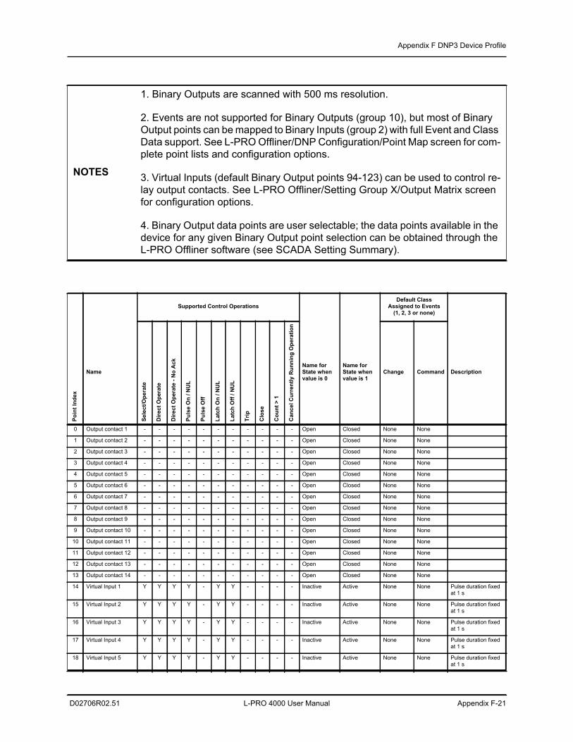
Appendix F DNP3 Device Profile
D02706R02.51 L-PRO 4000 User Manual Appendix F-21
NOTES
1. Binary Outputs are scanned with 500 ms resolution.
2. Events are not supported for Binary Outputs (group 10), but most of Binary Output points can be mapped to Binary Inputs (group 2) with full Event and Class Data support. See L-PRO Offliner/DNP Configuration/Point Map screen for com-plete point lists and configuration options.
3. Virtual Inputs (default Binary Output points 94-123) can be used to control re-lay output contacts. See L-PRO Offliner/Setting Group X/Output Matrix screen for configuration options.
4. Binary Output data points are user selectable; the data points available in the device for any given Binary Output point selection can be obtained through the L-PRO Offliner software (see SCADA Setting Summary).
Supported Control OperationsDefault Class
Assigned to Events(1, 2, 3 or none)
Poin
t Ind
ex
Name
Sele
ct/O
pera
te
Dire
ct O
pera
te
Dire
ct O
pera
te -
No
Ack
Puls
e O
n / N
UL
Puls
e O
ff
Latc
h O
n / N
UL
Latc
h O
ff / N
UL
Trip
Clo
se
Cou
nt >
1
Can
cel C
urre
ntly
Run
ning
Ope
ratio
n
Name for State when value is 0
Name for State when value is 1
Change Command Description
0 Output contact 1 - - - - - - - - - - - Open Closed None None
1 Output contact 2 - - - - - - - - - - - Open Closed None None
2 Output contact 3 - - - - - - - - - - - Open Closed None None
3 Output contact 4 - - - - - - - - - - - Open Closed None None
4 Output contact 5 - - - - - - - - - - - Open Closed None None
5 Output contact 6 - - - - - - - - - - - Open Closed None None
6 Output contact 7 - - - - - - - - - - - Open Closed None None
7 Output contact 8 - - - - - - - - - - - Open Closed None None
8 Output contact 9 - - - - - - - - - - - Open Closed None None
9 Output contact 10 - - - - - - - - - - - Open Closed None None
10 Output contact 11 - - - - - - - - - - - Open Closed None None
11 Output contact 12 - - - - - - - - - - - Open Closed None None
12 Output contact 13 - - - - - - - - - - - Open Closed None None
13 Output contact 14 - - - - - - - - - - - Open Closed None None
14 Virtual Input 1 Y Y Y Y - Y Y - - - - Inactive Active None None Pulse duration fixed at 1 s
15 Virtual Input 2 Y Y Y Y - Y Y - - - - Inactive Active None None Pulse duration fixed at 1 s
16 Virtual Input 3 Y Y Y Y - Y Y - - - - Inactive Active None None Pulse duration fixed at 1 s
17 Virtual Input 4 Y Y Y Y - Y Y - - - - Inactive Active None None Pulse duration fixed at 1 s
18 Virtual Input 5 Y Y Y Y - Y Y - - - - Inactive Active None None Pulse duration fixed at 1 s
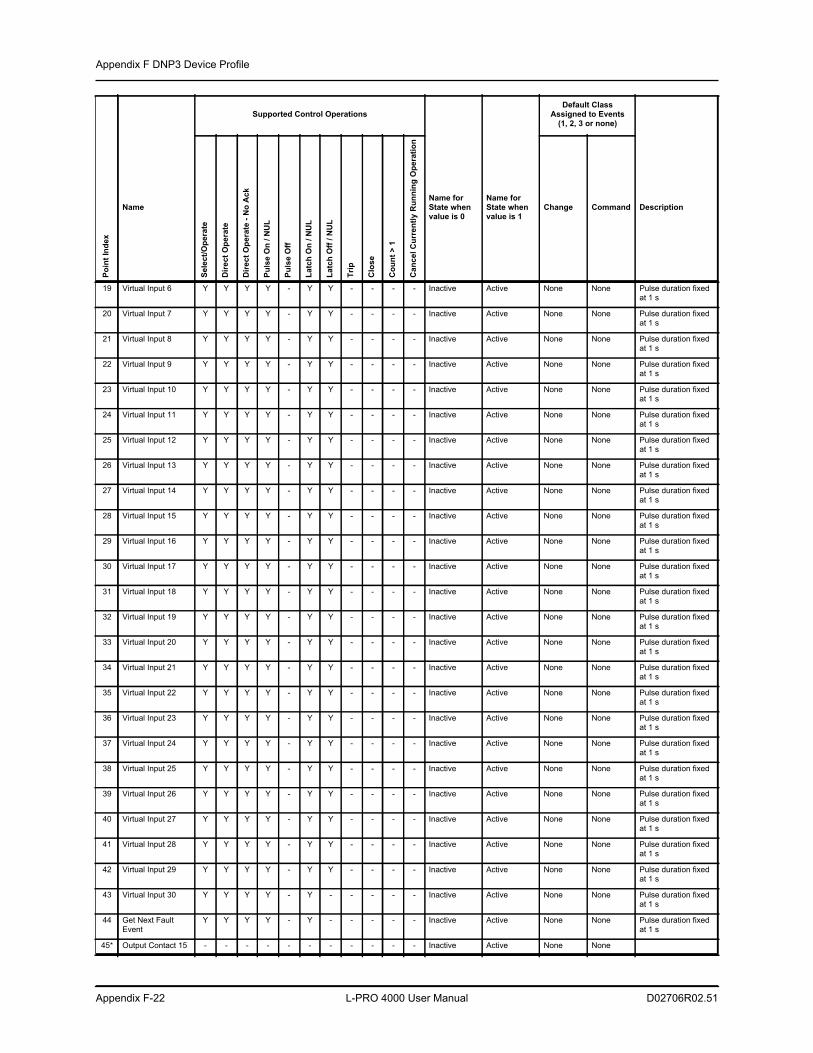
Appendix F DNP3 Device Profile
Appendix F-22 L-PRO 4000 User Manual D02706R02.51
19 Virtual Input 6 Y Y Y Y - Y Y - - - - Inactive Active None None Pulse duration fixed at 1 s
20 Virtual Input 7 Y Y Y Y - Y Y - - - - Inactive Active None None Pulse duration fixed at 1 s
21 Virtual Input 8 Y Y Y Y - Y Y - - - - Inactive Active None None Pulse duration fixed at 1 s
22 Virtual Input 9 Y Y Y Y - Y Y - - - - Inactive Active None None Pulse duration fixed at 1 s
23 Virtual Input 10 Y Y Y Y - Y Y - - - - Inactive Active None None Pulse duration fixed at 1 s
24 Virtual Input 11 Y Y Y Y - Y Y - - - - Inactive Active None None Pulse duration fixed at 1 s
25 Virtual Input 12 Y Y Y Y - Y Y - - - - Inactive Active None None Pulse duration fixed at 1 s
26 Virtual Input 13 Y Y Y Y - Y Y - - - - Inactive Active None None Pulse duration fixed at 1 s
27 Virtual Input 14 Y Y Y Y - Y Y - - - - Inactive Active None None Pulse duration fixed at 1 s
28 Virtual Input 15 Y Y Y Y - Y Y - - - - Inactive Active None None Pulse duration fixed at 1 s
29 Virtual Input 16 Y Y Y Y - Y Y - - - - Inactive Active None None Pulse duration fixed at 1 s
30 Virtual Input 17 Y Y Y Y - Y Y - - - - Inactive Active None None Pulse duration fixed at 1 s
31 Virtual Input 18 Y Y Y Y - Y Y - - - - Inactive Active None None Pulse duration fixed at 1 s
32 Virtual Input 19 Y Y Y Y - Y Y - - - - Inactive Active None None Pulse duration fixed at 1 s
33 Virtual Input 20 Y Y Y Y - Y Y - - - - Inactive Active None None Pulse duration fixed at 1 s
34 Virtual Input 21 Y Y Y Y - Y Y - - - - Inactive Active None None Pulse duration fixed at 1 s
35 Virtual Input 22 Y Y Y Y - Y Y - - - - Inactive Active None None Pulse duration fixed at 1 s
36 Virtual Input 23 Y Y Y Y - Y Y - - - - Inactive Active None None Pulse duration fixed at 1 s
37 Virtual Input 24 Y Y Y Y - Y Y - - - - Inactive Active None None Pulse duration fixed at 1 s
38 Virtual Input 25 Y Y Y Y - Y Y - - - - Inactive Active None None Pulse duration fixed at 1 s
39 Virtual Input 26 Y Y Y Y - Y Y - - - - Inactive Active None None Pulse duration fixed at 1 s
40 Virtual Input 27 Y Y Y Y - Y Y - - - - Inactive Active None None Pulse duration fixed at 1 s
41 Virtual Input 28 Y Y Y Y - Y Y - - - - Inactive Active None None Pulse duration fixed at 1 s
42 Virtual Input 29 Y Y Y Y - Y Y - - - - Inactive Active None None Pulse duration fixed at 1 s
43 Virtual Input 30 Y Y Y Y - Y - - - - - Inactive Active None None Pulse duration fixed at 1 s
44 Get Next FaultEvent
Y Y Y Y - Y - - - - - Inactive Active None None Pulse duration fixed at 1 s
45* Output Contact 15 - - - - - - - - - - - Inactive Active None None
Supported Control OperationsDefault Class
Assigned to Events(1, 2, 3 or none)
Poin
t Ind
ex
NameSe
lect
/Ope
rate
Dire
ct O
pera
te
Dire
ct O
pera
te -
No
Ack
Puls
e O
n / N
UL
Puls
e O
ff
Latc
h O
n / N
UL
Latc
h O
ff / N
UL
Trip
Clo
se
Cou
nt >
1
Can
cel C
urre
ntly
Run
ning
Ope
ratio
n
Name for State when value is 0
Name for State when value is 1
Change Command Description
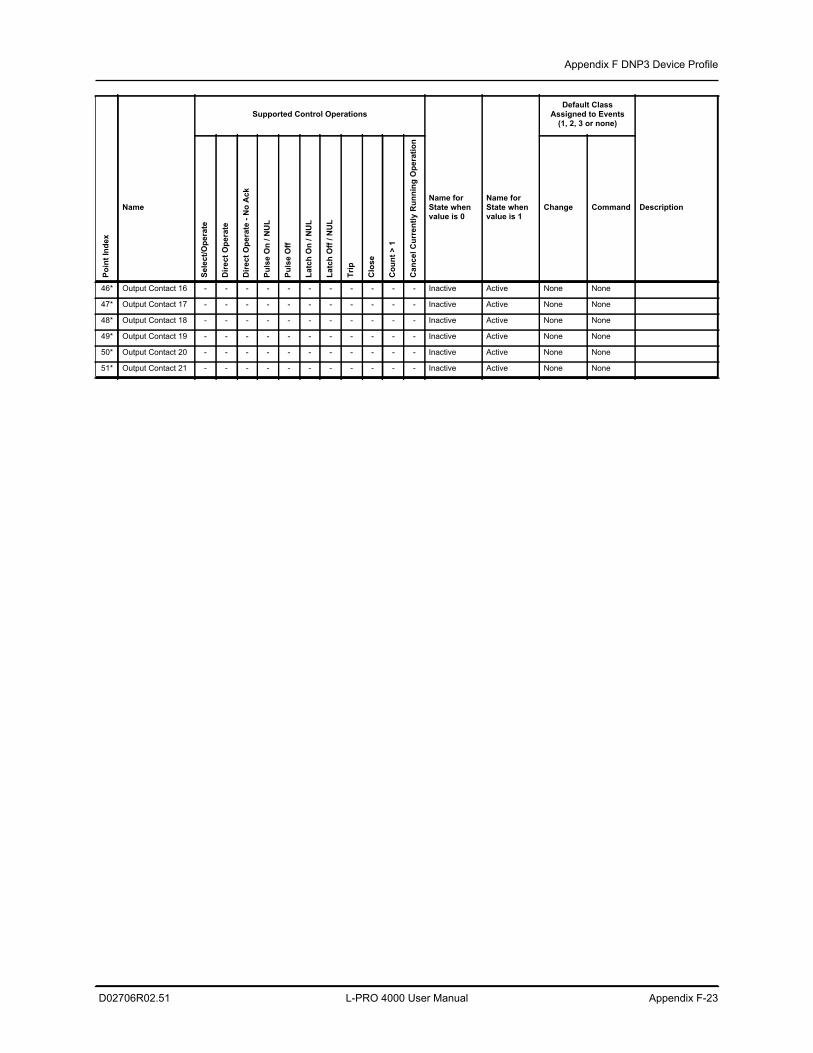
Appendix F DNP3 Device Profile
D02706R02.51 L-PRO 4000 User Manual Appendix F-23
46* Output Contact 16 - - - - - - - - - - - Inactive Active None None
47* Output Contact 17 - - - - - - - - - - - Inactive Active None None
48* Output Contact 18 - - - - - - - - - - - Inactive Active None None
49* Output Contact 19 - - - - - - - - - - - Inactive Active None None
50* Output Contact 20 - - - - - - - - - - - Inactive Active None None
51* Output Contact 21 - - - - - - - - - - - Inactive Active None None
Supported Control OperationsDefault Class
Assigned to Events(1, 2, 3 or none)
Poin
t Ind
ex
NameSe
lect
/Ope
rate
Dire
ct O
pera
te
Dire
ct O
pera
te -
No
Ack
Puls
e O
n / N
UL
Puls
e O
ff
Latc
h O
n / N
UL
Latc
h O
ff / N
UL
Trip
Clo
se
Cou
nt >
1
Can
cel C
urre
ntly
Run
ning
Ope
ratio
n
Name for State when value is 0
Name for State when value is 1
Change Command Description
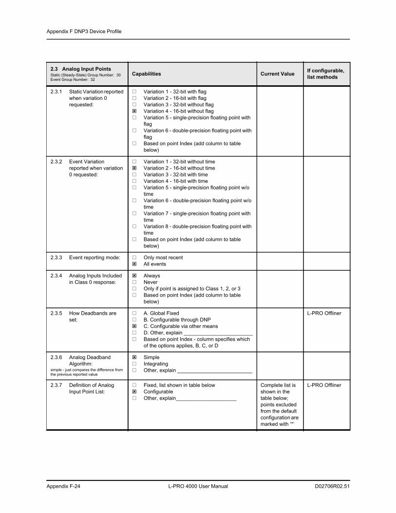
Appendix F DNP3 Device Profile
Appendix F-24 L-PRO 4000 User Manual D02706R02.51
2.3 Analog Input PointsStatic (Steady-State) Group Number: 30Event Group Number: 32
Capabilities Current Value If configurable, list methods
2.3.1 Static Variation reported when variation 0 requested:
Variation 1 - 32-bit with flag Variation 2 - 16-bit with flag Variation 3 - 32-bit without flag Variation 4 - 16-bit without flag Variation 5 - single-precision floating point with
flag Variation 6 - double-precision floating point with
flag Based on point Index (add column to table
below)
2.3.2 Event Variation reported when variation 0 requested:
Variation 1 - 32-bit without time Variation 2 - 16-bit without time Variation 3 - 32-bit with time Variation 4 - 16-bit with time Variation 5 - single-precision floating point w/o
time Variation 6 - double-precision floating point w/o
time Variation 7 - single-precision floating point with
time Variation 8 - double-precision floating point with
time Based on point Index (add column to table
below)
2.3.3 Event reporting mode: Only most recent All events
2.3.4 Analog Inputs Included in Class 0 response:
Always Never Only if point is assigned to Class 1, 2, or 3 Based on point Index (add column to table
below)
2.3.5 How Deadbands are set:
A. Global Fixed B. Configurable through DNP C. Configurable via other means D. Other, explain ________________________ Based on point Index - column specifies which
of the options applies, B, C, or D
L-PRO Offliner
2.3.6 Analog Deadband Algorithm:
simple - just compares the difference from the previous reported value
Simple Integrating Other, explain __________________________
2.3.7 Definition of Analog Input Point List:
Fixed, list shown in table below Configurable Other, explain_____________________
Complete list is shown in the table below; points excluded from the default configuration are marked with ‘*’
L-PRO Offliner
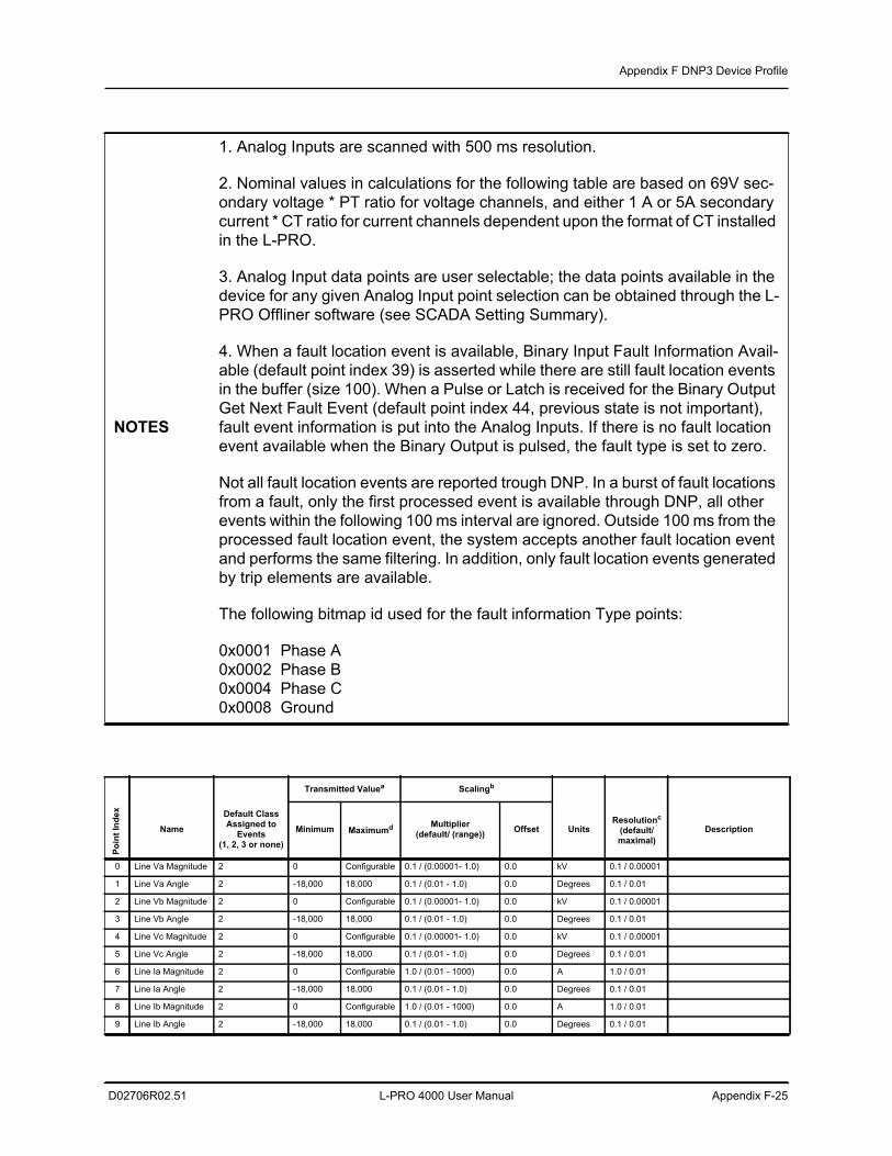
Appendix F DNP3 Device Profile
D02706R02.51 L-PRO 4000 User Manual Appendix F-25
NOTES
1. Analog Inputs are scanned with 500 ms resolution.
2. Nominal values in calculations for the following table are based on 69V sec-ondary voltage * PT ratio for voltage channels, and either 1 A or 5A secondary current * CT ratio for current channels dependent upon the format of CT installed in the L-PRO.
3. Analog Input data points are user selectable; the data points available in the device for any given Analog Input point selection can be obtained through the L-PRO Offliner software (see SCADA Setting Summary).
4. When a fault location event is available, Binary Input Fault Information Avail-able (default point index 39) is asserted while there are still fault location events in the buffer (size 100). When a Pulse or Latch is received for the Binary Output Get Next Fault Event (default point index 44, previous state is not important), fault event information is put into the Analog Inputs. If there is no fault location event available when the Binary Output is pulsed, the fault type is set to zero.
Not all fault location events are reported trough DNP. In a burst of fault locations from a fault, only the first processed event is available through DNP, all other events within the following 100 ms interval are ignored. Outside 100 ms from the processed fault location event, the system accepts another fault location event and performs the same filtering. In addition, only fault location events generated by trip elements are available.
The following bitmap id used for the fault information Type points:
0x0001 Phase A0x0002 Phase B0x0004 Phase C0x0008 Ground
Transmitted Valuea Scalingb
Poin
t Ind
ex
Name
Default ClassAssigned to
Events(1, 2, 3 or none)
Minimum Maximumd Multiplier(default/ (range)) Offset Units
Resolutionc
(default/ maximal)
Description
0 Line Va Magnitude 2 0 Configurable 0.1 / (0.00001- 1.0) 0.0 kV 0.1 / 0.00001
1 Line Va Angle 2 -18,000 18,000 0.1 / (0.01 - 1.0) 0.0 Degrees 0.1 / 0.01
2 Line Vb Magnitude 2 0 Configurable 0.1 / (0.00001- 1.0) 0.0 kV 0.1 / 0.00001
3 Line Vb Angle 2 -18,000 18,000 0.1 / (0.01 - 1.0) 0.0 Degrees 0.1 / 0.01
4 Line Vc Magnitude 2 0 Configurable 0.1 / (0.00001- 1.0) 0.0 kV 0.1 / 0.00001
5 Line Vc Angle 2 -18,000 18,000 0.1 / (0.01 - 1.0) 0.0 Degrees 0.1 / 0.01
6 Line Ia Magnitude 2 0 Configurable 1.0 / (0.01 - 1000) 0.0 A 1.0 / 0.01
7 Line Ia Angle 2 -18,000 18,000 0.1 / (0.01 - 1.0) 0.0 Degrees 0.1 / 0.01
8 Line Ib Magnitude 2 0 Configurable 1.0 / (0.01 - 1000) 0.0 A 1.0 / 0.01
9 Line Ib Angle 2 -18,000 18,000 0.1 / (0.01 - 1.0) 0.0 Degrees 0.1 / 0.01
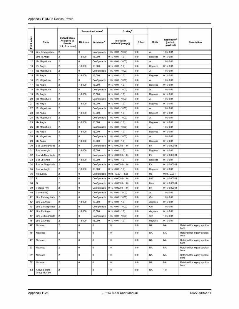
Appendix F DNP3 Device Profile
Appendix F-26 L-PRO 4000 User Manual D02706R02.51
10 Line Ic Magnitude 2 0 Configurable 1.0 / (0.01 - 1000) 0.0 A 1.0 / 0.01
11 Line Ic Angle 2 -18,000 18,000 0.1 / (0.01 - 1.0) 0.0 Degrees 0.1 / 0.01
12 I2a Magnitude 2 0 Configurable 1.0 / (0.01 - 1000) 0.0 A 1.0 / 0.01
13 I2a Angle 2 -18,000 18,000 0.1 / (0.01 - 1.0) 0.0 Degrees 0.1 / 0.01
14 I2b Magnitude 2 0 Configurable 1.0 / (0.01 - 1000) 0.0 A 1.0 / 0.01
15 I2b Angle 2 -18,000 18,000 0.1 / (0.01 - 1.0) 0.0 Degrees 0.1 / 0.01
16 I2c Magnitude 2 0 Configurable 1.0 / (0.01 - 1000) 0.0 A 1.0 / 0.01
17 I2c Angle 2 -18,000 18,000 0.1 / (0.01 - 1.0) 0.0 Degrees 0.1 / 0.01
18 I3a Magnitude 2 0 Configurable 1.0 / (0.01 - 1000) 0.0 A 1.0 / 0.01
19 I3a Angle 2 -18,000 18,000 0.1 / (0.01 - 1.0) 0.0 Degrees 0.1 / 0.01
20 I3b Magnitude 2 0 Configurable 1.0 / (0.01 - 1000) 0.0 A 1.0 / 0.01
21 I3b Angle 2 -18,000 18,000 0.1 / (0.01 - 1.0) 0.0 Degrees 0.1 / 0.01
22 I3c Magnitude 2 0 Configurable 1.0 / (0.01 - 1000) 0.0 A 1.0 / 0.01
23 I3c Angle 2 -18,000 18,000 0.1 / (0.01 - 1.0) 0.0 Degrees 0.1 / 0.01
24 I4a Magnitude 2 0 Configurable 1.0 / (0.01 - 1000) 0.0 A 1.0 / 0.01
25 I4a Angle 2 -18,000 18,000 0.1 / (0.01 - 1.0) 0.0 Degrees 0.1 / 0.01
26 I4b Magnitude 2 0 Configurable 1.0 / (0.01 - 1000) 0.0 A 1.0 / 0.01
27 I4b Angle 2 -18,000 18,000 0.1 / (0.01 - 1.0) 0.0 Degrees 0.1 / 0.01
28 I4c Magnitude 2 0 Configurable 1.0 / (0.01 - 1000) 0.0 A 1.0 / 0.01
29 I4c Angle 2 -18,000 18,000 0.1 / (0.01 - 1.0) 0.0 Degrees 0.1 / 0.01
30 Bus Va Magnitude 2 0 Configurable 0.1 / (0.00001- 1.0) 0.0 kV 0.1 / 0.00001
31 Bus Va Angle 2 -18,000 18,000 0.1 / (0.01 - 1.0) 0.0 Degrees 0.1 / 0.01
32 Bus Vb Magnitude 2 0 Configurable 0.1 / (0.00001- 1.0) 0.0 kV 0.1 / 0.00001
33 Bus Vb Angle 2 -18,000 18,000 0.1 / (0.01 - 1.0) 0.0 Degrees 0.1 / 0.01
34 Bus Vc Magnitude 2 0 Configurable 0.1 / (0.00001- 1.0) 0.0 kV 0.1 / 0.00001
35 Bus Vc Angle 2 -18,000 18,000 0.1 / (0.01 - 1.0) 0.0 Degrees 0.1 / 0.01
36 Frequency 2 0 Configurable 0.01 / (0.001 - 1.0) 0.0 Hz 0.01 / 0.001
37 P 2 0 Configurable 0.1 / (0.00001- 1.0) 0.0 MW 0.1 / 0.00001
38 Q 2 0 Configurable 0.1 / (0.00001- 1.0) 0.0 Mvar 0.1 / 0.00001
39 Voltage (V1) 2 0 Configurable 0.1 / (0.00001- 1.0) 0.0 kV 0.1 / 0.00001
40 Current (I1) 2 0 Configurable 1.0 / (0.01 - 1000) 0.0 A 1.0 / 0.01
41* Line Za Magnitude 2 0 Configurable 1.0 / (0.01 - 1000) 0.0 Om 1.0 / 0.01
42* Line Za Angle 2 -18,000 18,000 0.1 / (0.01 - 1.0) 0.0 degrees 0.1 / 0.01
43* Line Zb Magnitude 2 0 Configurable 1.0 / (0.01 - 1000) 0.0 Om 1.0 / 0.01
44* Line Zb Angle 2 -18,000 18,000 0.1 / (0.01 - 1.0) 0.0 degrees 0.1 / 0.01
45* Line Zc Magnitude 2 0 Configurable 1.0 / (0.01 - 1000) 0.0 Om 1.0 / 0.01
46* Line Zc Angle 2 -18,000 18,000 0.1 / (0.01 - 1.0) 0.0 degrees 0.1 / 0.01
47* Not used 2 0 0 1.0 0.0 NA NA Retained for legacy applica-tions
48* Not used 2 0 0 1.0 0.0 NA NA Retained for legacy applica-tions
49* Not used 2 0 0 1.0 0.0 NA NA Retained for legacy applica-tions
50* Not used 2 0 0 1.0 0.0 NA NA Retained for legacy applica-tions
51* Not used 2 0 0 1.0 0.0 NA NA Retained for legacy applica-tions
52* Not used 2 0 0 1.0 0.0 NA NA Retained for legacy applica-tions
53 Active Setting Group Number
2 1 8 1.0 0.0 NA 1.0
Transmitted Valuea ScalingbPo
int I
ndex
Name
Default ClassAssigned to
Events(1, 2, 3 or none)
Minimum Maximumd Multiplier(default/ (range)) Offset Units
Resolutionc
(default/ maximal)
Description
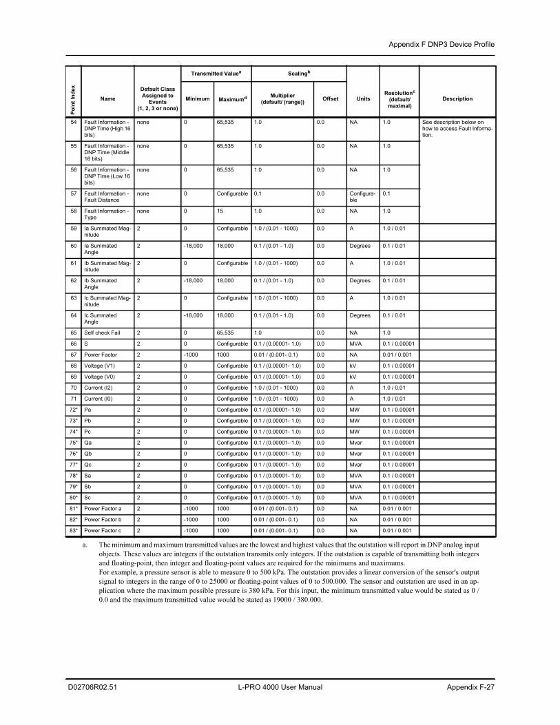
Appendix F DNP3 Device Profile
D02706R02.51 L-PRO 4000 User Manual Appendix F-27
54 Fault Information - DNP Time (High 16 bits)
none 0 65,535 1.0 0.0 NA 1.0 See description below on how to access Fault Informa-tion.
55 Fault Information - DNP Time (Middle 16 bits)
none 0 65,535 1.0 0.0 NA 1.0
56 Fault Information - DNP Time (Low 16 bits)
none 0 65,535 1.0 0.0 NA 1.0
57 Fault Information - Fault Distance
none 0 Configurable 0.1 0.0 Configura-ble
0.1
58 Fault Information - Type
none 0 15 1.0 0.0 NA 1.0
59 Ia Summated Mag-nitude
2 0 Configurable 1.0 / (0.01 - 1000) 0.0 A 1.0 / 0.01
60 Ia Summated Angle
2 -18,000 18,000 0.1 / (0.01 - 1.0) 0.0 Degrees 0.1 / 0.01
61 Ib Summated Mag-nitude
2 0 Configurable 1.0 / (0.01 - 1000) 0.0 A 1.0 / 0.01
62 Ib Summated Angle
2 -18,000 18,000 0.1 / (0.01 - 1.0) 0.0 Degrees 0.1 / 0.01
63 Ic Summated Mag-nitude
2 0 Configurable 1.0 / (0.01 - 1000) 0.0 A 1.0 / 0.01
64 Ic Summated Angle
2 -18,000 18,000 0.1 / (0.01 - 1.0) 0.0 Degrees 0.1 / 0.01
65 Self check Fail 2 0 65,535 1.0 0.0 NA 1.0
66 S 2 0 Configurable 0.1 / (0.00001- 1.0) 0.0 MVA 0.1 / 0.00001
67 Power Factor 2 -1000 1000 0.01 / (0.001- 0.1) 0.0 NA 0.01 / 0.001
68 Voltage (V1) 2 0 Configurable 0.1 / (0.00001- 1.0) 0.0 kV 0.1 / 0.00001
69 Voltage (V0) 2 0 Configurable 0.1 / (0.00001- 1.0) 0.0 kV 0.1 / 0.00001
70 Current (I2) 2 0 Configurable 1.0 / (0.01 - 1000) 0.0 A 1.0 / 0.01
71 Current (I0) 2 0 Configurable 1.0 / (0.01 - 1000) 0.0 A 1.0 / 0.01
72* Pa 2 0 Configurable 0.1 / (0.00001- 1.0) 0.0 MW 0.1 / 0.00001
73* Pb 2 0 Configurable 0.1 / (0.00001- 1.0) 0.0 MW 0.1 / 0.00001
74* Pc 2 0 Configurable 0.1 / (0.00001- 1.0) 0.0 MW 0.1 / 0.00001
75* Qa 2 0 Configurable 0.1 / (0.00001- 1.0) 0.0 Mvar 0.1 / 0.00001
76* Qb 2 0 Configurable 0.1 / (0.00001- 1.0) 0.0 Mvar 0.1 / 0.00001
77* Qc 2 0 Configurable 0.1 / (0.00001- 1.0) 0.0 Mvar 0.1 / 0.00001
78* Sa 2 0 Configurable 0.1 / (0.00001- 1.0) 0.0 MVA 0.1 / 0.00001
79* Sb 2 0 Configurable 0.1 / (0.00001- 1.0) 0.0 MVA 0.1 / 0.00001
80* Sc 2 0 Configurable 0.1 / (0.00001- 1.0) 0.0 MVA 0.1 / 0.00001
81* Power Factor a 2 -1000 1000 0.01 / (0.001- 0.1) 0.0 NA 0.01 / 0.001
82* Power Factor b 2 -1000 1000 0.01 / (0.001- 0.1) 0.0 NA 0.01 / 0.001
83* Power Factor c 2 -1000 1000 0.01 / (0.001- 0.1) 0.0 NA 0.01 / 0.001
a. The minimum and maximum transmitted values are the lowest and highest values that the outstation will report in DNP analog inputobjects. These values are integers if the outstation transmits only integers. If the outstation is capable of transmitting both integersand floating-point, then integer and floating-point values are required for the minimums and maximums.For example, a pressure sensor is able to measure 0 to 500 kPa. The outstation provides a linear conversion of the sensor's outputsignal to integers in the range of 0 to 25000 or floating-point values of 0 to 500.000. The sensor and outstation are used in an ap-plication where the maximum possible pressure is 380 kPa. For this input, the minimum transmitted value would be stated as 0 /0.0 and the maximum transmitted value would be stated as 19000 / 380.000.
Transmitted Valuea ScalingbPo
int I
ndex
Name
Default ClassAssigned to
Events(1, 2, 3 or none)
Minimum Maximumd Multiplier(default/ (range)) Offset Units
Resolutionc
(default/ maximal)
Description
Appendix F DNP3 Device Profile
Appendix F-28 L-PRO 4000 User Manual D02706R02.51
b. The scaling information for each point specifies how data transmitted in integer variations (16 bit and 32 bit) is converted to engi-neering units when received by the Master (i.e. scaled according to the equation: scaled value = multiplier * raw + offset). Scalingis not applied to Floating point variations since they are already transmitted in engineering units.
c. Resolution is the smallest change that may be detected in the value due to quantization errors and is given in the units shown in theprevious column. This parameter does not represent the accuracy of the measurement.
d. Maximal values are calculated as (2 * Configured Nominal / Multiplier) for voltage channels and as (40 * Configured Nominal /Multiplier) for current channels (see Note 2 above for the nominal definitions).
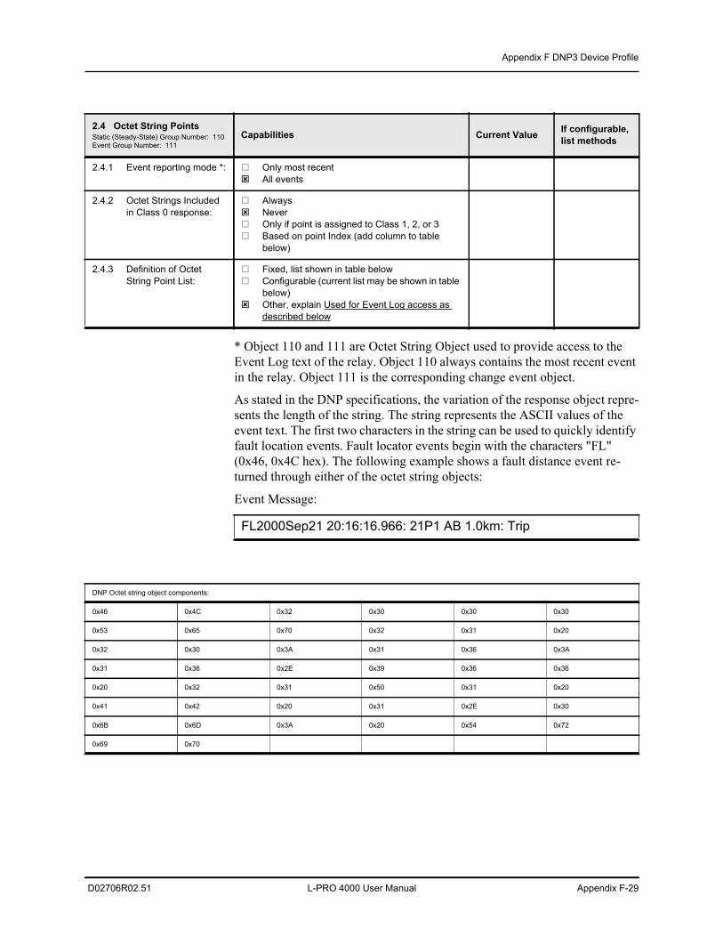
Appendix F DNP3 Device Profile
D02706R02.51 L-PRO 4000 User Manual Appendix F-29
* Object 110 and 111 are Octet String Object used to provide access to the Event Log text of the relay. Object 110 always contains the most recent event in the relay. Object 111 is the corresponding change event object.
As stated in the DNP specifications, the variation of the response object repre-sents the length of the string. The string represents the ASCII values of the event text. The first two characters in the string can be used to quickly identify fault location events. Fault locator events begin with the characters "FL" (0x46, 0x4C hex). The following example shows a fault distance event re-turned through either of the octet string objects:
Event Message:
2.4 Octet String PointsStatic (Steady-State) Group Number: 110Event Group Number: 111
Capabilities Current Value If configurable, list methods
2.4.1 Event reporting mode *: Only most recent All events
2.4.2 Octet Strings Included in Class 0 response:
Always Never Only if point is assigned to Class 1, 2, or 3 Based on point Index (add column to table
below)
2.4.3 Definition of Octet String Point List:
Fixed, list shown in table below Configurable (current list may be shown in table
below) Other, explain Used for Event Log access as
described below
FL2000Sep21 20:16:16.966: 21P1 AB 1.0km: Trip
DNP Octet string object components:
0x46 0x4C 0x32 0x30 0x30 0x30
0x53 0x65 0x70 0x32 0x31 0x20
0x32 0x30 0x3A 0x31 0x36 0x3A
0x31 0x36 0x2E 0x39 0x36 0x36
0x20 0x32 0x31 0x50 0x31 0x20
0x41 0x42 0x20 0x31 0x2E 0x30
0x6B 0x6D 0x3A 0x20 0x54 0x72
0x69 0x70
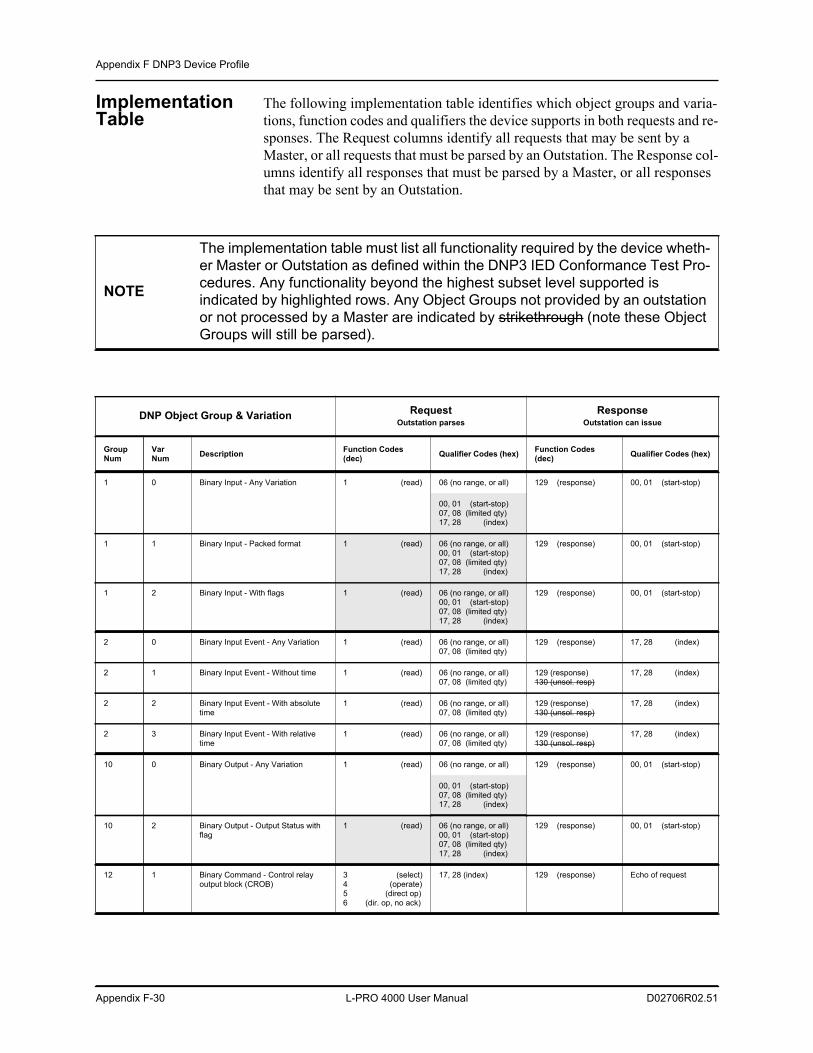
Appendix F DNP3 Device Profile
Appendix F-30 L-PRO 4000 User Manual D02706R02.51
Implementation Table
The following implementation table identifies which object groups and varia-tions, function codes and qualifiers the device supports in both requests and re-sponses. The Request columns identify all requests that may be sent by a Master, or all requests that must be parsed by an Outstation. The Response col-umns identify all responses that must be parsed by a Master, or all responses that may be sent by an Outstation.
NOTE
The implementation table must list all functionality required by the device wheth-er Master or Outstation as defined within the DNP3 IED Conformance Test Pro-cedures. Any functionality beyond the highest subset level supported is indicated by highlighted rows. Any Object Groups not provided by an outstation or not processed by a Master are indicated by strikethrough (note these Object Groups will still be parsed).
DNP Object Group & Variation RequestOutstation parses
ResponseOutstation can issue
Group Num
Var Num Description Function Codes
(dec) Qualifier Codes (hex) Function Codes (dec) Qualifier Codes (hex)
1 0 Binary Input - Any Variation 1 (read) 06 (no range, or all) 129 (response) 00, 01 (start-stop)
00, 01 (start-stop) 07, 08 (limited qty) 17, 28 (index)
1 1 Binary Input - Packed format 1 (read) 06 (no range, or all) 00, 01 (start-stop) 07, 08 (limited qty) 17, 28 (index)
129 (response) 00, 01 (start-stop)
1 2 Binary Input - With flags 1 (read) 06 (no range, or all) 00, 01 (start-stop) 07, 08 (limited qty) 17, 28 (index)
129 (response) 00, 01 (start-stop)
2 0 Binary Input Event - Any Variation 1 (read) 06 (no range, or all) 07, 08 (limited qty)
129 (response) 17, 28 (index)
2 1 Binary Input Event - Without time 1 (read) 06 (no range, or all) 07, 08 (limited qty)
129 (response)130 (unsol. resp)
17, 28 (index)
2 2 Binary Input Event - With absolute time
1 (read) 06 (no range, or all) 07, 08 (limited qty)
129 (response)130 (unsol. resp)
17, 28 (index)
2 3 Binary Input Event - With relative time
1 (read) 06 (no range, or all) 07, 08 (limited qty)
129 (response)130 (unsol. resp)
17, 28 (index)
10 0 Binary Output - Any Variation 1 (read) 06 (no range, or all) 129 (response) 00, 01 (start-stop)
00, 01 (start-stop) 07, 08 (limited qty) 17, 28 (index)
10 2 Binary Output - Output Status with flag
1 (read) 06 (no range, or all) 00, 01 (start-stop) 07, 08 (limited qty) 17, 28 (index)
129 (response) 00, 01 (start-stop)
12 1 Binary Command - Control relay output block (CROB)
3 (select)4 (operate)5 (direct op)6 (dir. op, no ack)
17, 28 (index) 129 (response) Echo of request
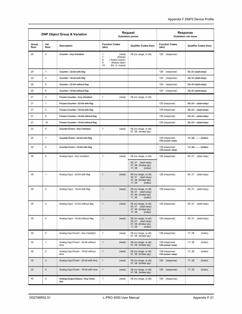
Appendix F DNP3 Device Profile
D02706R02.51 L-PRO 4000 User Manual Appendix F-31
20 0 Counter - Any Variation 1 (read)7 (freeze)8 ( freeze noack)9 (freeze clear)10 (frz. cl. noack)
06 (no range, or all) 129 (response)
20 1 Counter - 32-bit with flag 129 (response) 00, 01 (start-stop)
20 2 Counter - 16-bit with flag 129 (response) 00, 01 (start-stop)
20 5 Counter - 32-bit without flag 129 (response) 00, 01 (start-stop)
20 6 Counter - 16-bit without flag 129 (response) 00, 01 (start-stop)
21 0 Frozen Counter - Any Variation 1 (read) 06 (no range, or all)
21 1 Frozen Counter - 32-bit with flag 129 (response) 00, 01 (start-stop)
21 2 Frozen Counter - 16-bit with flag 129 (response) 00, 01 (start-stop)
21 9 Frozen Counter - 32-bit without flag 129 (response) 00, 01 (start-stop)
21 10 Frozen Counter - 16-bit without flag 129 (response) 00, 01 (start-stop)
22 0 Counter Event - Any Variation 1 (read) 06 (no range, or all) 07, 08 (limited qty)
22 1 Counter Event - 32-bit with flag 129 (response)130 (unsol. resp)
17, 28 (index)
22 2 Counter Event - 16-bit with flag 129 (response)130 (unsol. resp)
17, 28 (index)
30 0 Analog Input - Any Variation 1 (read) 06 (no range, or all) 129 (response) 00, 01 (start-stop)
00, 01 (start-stop) 07, 08 (limited qty) 17, 28 (index)
30 1 Analog Input - 32-bit with flag 1 (read) 06 (no range, or all) 00, 01 (start-stop) 07, 08 (limited qty) 17, 28 (index)
129 (response) 00, 01 (start-stop)
30 2 Analog Input - 16-bit with flag 1 (read) 06 (no range, or all) 00, 01 (start-stop) 07, 08 (limited qty) 17, 28 (index)
129 (response) 00, 01 (start-stop)
30 3 Analog Input - 32-bit without flag 1 (read) 06 (no range, or all) 00, 01 (start-stop) 07, 08 (limited qty) 17, 28 (index)
129 (response) 00, 01 (start-stop)
30 4 Analog Input - 16-bit without flag 1 (read) 06 (no range, or all) 00, 01 (start-stop) 07, 08 (limited qty) 17, 28 (index)
129 (response) 00, 01 (start-stop)
32 0 Analog Input Event - Any Variation 1 (read) 06 (no range, or all)07, 08 (limited qty)
129 (response) 17, 28 (index)
32 1 Analog Input Event - 32-bit without time
1 (read) 06 (no range, or all)07, 08 (limited qty)
129 (response)130 (unsol. resp)
17, 28 (index)
32 2 Analog Input Event - 16-bit without time
1 (read) 06 (no range, or all)07, 08 (limited qty)
129 (response)130 (unsol. resp)
17, 28 (index)
32 3 Analog Input Event - 32-bit with time 1 (read) 06 (no range, or all)07, 08 (limited qty)
129 (response) 17, 28 (index)
32 4 Analog Input Event - 16-bit with time 1 (read) 06 (no range, or all)07, 08 (limited qty)
129 (response) 17, 28 (index)
40 0 Analog Output Status - Any Varia-tion
1 (read) 06 (no range, or all) 129 (response)
DNP Object Group & Variation RequestOutstation parses
ResponseOutstation can issue
Group Num
Var Num Description Function Codes
(dec) Qualifier Codes (hex) Function Codes (dec) Qualifier Codes (hex)
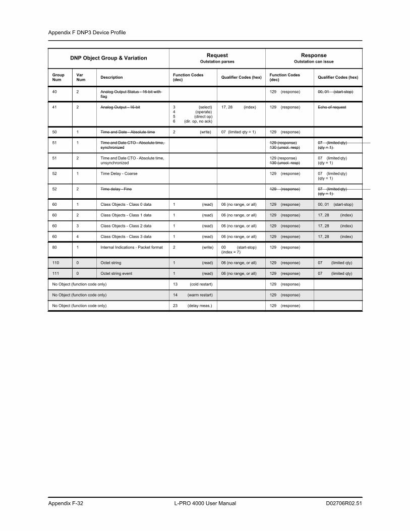
Appendix F DNP3 Device Profile
Appendix F-32 L-PRO 4000 User Manual D02706R02.51
40 2 Analog Output Status - 16-bit with flag
129 (response) 00, 01 (start-stop)
41 2 Analog Output - 16-bit 3 (select)4 (operate)5 (direct op)6 (dir. op, no ack)
17, 28 (index) 129 (response) Echo of request
50 1 Time and Date - Absolute time 2 (write) 07 (limited qty = 1) 129 (response)
51 1 Time and Date CTO - Absolute time, synchronized
129 (response)130 (unsol. resp)
07 (limited qty) (qty = 1)
51 2 Time and Date CTO - Absolute time, unsynchronized
129 (response)130 (unsol. resp)
07 (limited qty) (qty = 1)
52 1 Time Delay - Coarse 129 (response) 07 (limited qty) (qty = 1)
52 2 Time delay - Fine 129 (response) 07 (limited qty) (qty = 1)
60 1 Class Objects - Class 0 data 1 (read) 06 (no range, or all) 129 (response) 00, 01 (start-stop)
60 2 Class Objects - Class 1 data 1 (read) 06 (no range, or all) 129 (response) 17, 28 (index)
60 3 Class Objects - Class 2 data 1 (read) 06 (no range, or all) 129 (response) 17, 28 (index)
60 4 Class Objects - Class 3 data 1 (read) 06 (no range, or all) 129 (response) 17, 28 (index)
80 1 Internal Indications - Packet format 2 (write) 00 (start-stop) (index = 7)
129 (response)
110 0 Octet string 1 (read) 06 (no range, or all) 129 (response) 07 (limited qty)
111 0 Octet string event 1 (read) 06 (no range, or all) 129 (response) 07 (limited qty)
No Object (function code only) 13 (cold restart) 129 (response)
No Object (function code only) 14 (warm restart) 129 (response)
No Object (function code only) 23 (delay meas.) 129 (response)
DNP Object Group & Variation RequestOutstation parses
ResponseOutstation can issue
Group Num
Var Num Description Function Codes
(dec) Qualifier Codes (hex) Function Codes (dec) Qualifier Codes (hex)
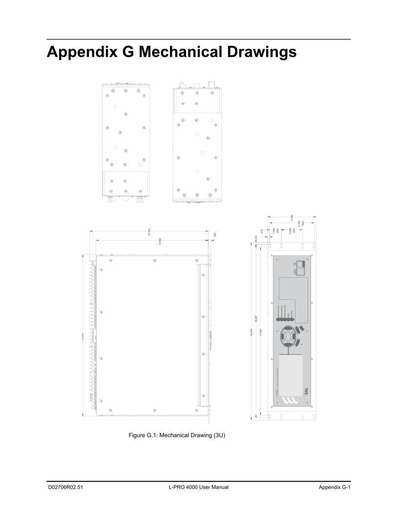
D02706R02.51 L-PRO 4000 User Manual Appendix G-1
Appendix G Mechanical Drawings
Figure G.1: Mechanical Drawing (3U)
18.9
70
17.9
53
18.5
47
.21
2
.215
5.1
80
2.2
50
(typ)
1.2
50
(typ)
4.7
50
(typ)
17
.41
0
12
.06
2
12
.74
2
.32
6
RE
LA
Y F
UN
CT
ION
AL
IRIG
-B F
UN
CT
ION
AL
SE
RV
ICE
RE
QU
IRE
D
TE
ST
MO
DE
AL
AR
M
LIN
E P
RO
TE
CT
ION
RE
LA
YL-
PRO
X
10
0B
AS
E-T
(11
9)
(150
)
US
B
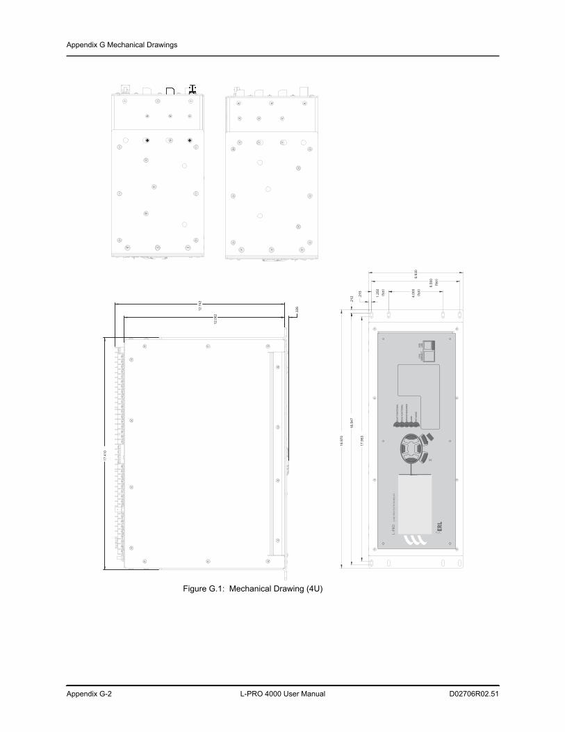
Appendix G Mechanical Drawings
Appendix G-2 L-PRO 4000 User Manual D02706R02.51
Figure G.1: Mechanical Drawing (4U)
.32
6
17
.41
0
12
.74
2
12
.06
2
18.9
70
17
.95
3
18.5
47
.21
2 .215
6.9
30
4.0
00
(typ)
1.2
50
(typ)
6.5
00
(typ)
RE
LA
Y F
UN
CT
ION
AL
IRIG
-B F
UN
CT
ION
AL
SE
RV
ICE
RE
QU
IRE
D
TE
ST
MO
DE
ALA
RM
LIN
E P
RO
TE
CT
ION
RE
LA
YL-
PRO
X
100B
AS
E-T
(11
9)
(15
0)
US
B
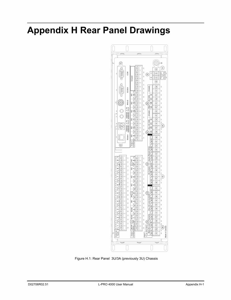
D02706R02.51 L-PRO 4000 User Manual Appendix H-1
Appendix H Rear Panel Drawings
Figure H.1: Rear Panel 3U/3A (previously 3U) Chassis
Po
we
r S
up
ply
±1
0%
48
to
25
0 V
dc
10
0 to
24
0 V
ac
I1A
I2A
I3A
I4A
I1B
I2B
I3B
I4B
I1C
I2C
I3C
I4C
Inp
ut
1A
50
Hz
5A
60
Hz
Main
AC
Lin
e C
urr
ents
Ma
de
in
Ca
na
da
AC
Curr
ent In
puts
(R
ecord
Only
)A
ux.A
C L
ine
Cu
rre
nts
300
312
324
301
313
325
302
314
326
303
315
327
304
316
328
305
317
329
306
318
330
307
319
331
308
320
332
309
321
333
310
322
334
336
311
323
335
337
VA
VA
VB
VB
VC
VC
NN
Aux.A
C V
olts
Main
AC
Volts
Un
use
dU
nu
se
d
Un
use
d
200
218
201
219
202
220
203
221
204
222
205
223
206
224
207
225
208
226
209
227
210
228
211
229
212
230
213
231
214
232
215
233
216
234
217
235
RE
LA
YIN
OP
ER
AT
IVE
NC
NO
NC
NO
NC
NO
NO
NO
NO
NO
NO
NO
NO
NO
NO
NO
NO
NO
Outp
ut
Conta
cts
Ou
tpu
tC
onta
cts
67
81
23
91
011
12
13
14
45
12
34
56
78
9E
xte
rnal
Inputs
100
101
102
103
104
105
106
107
108
109
110
111
112
113
114
115
116
117
48
12
52
50
V4
81
25
25
0V
48
12
52
50
V4
81
25
25
0V
48
125
250
V48
125
250
V4
81
25
25
0V
48
12
52
50
V4
81
25
25
0V
Mo
de
mIR
IG-B
SC
AD
AC
OM
100B
AS
E-
1000B
AS
E-
FX
TLX
TX
100B
AS
E-
1000B
AS
E-
FX
TLX
TX
RXRX
TXTX
118
119
120
121
122
123
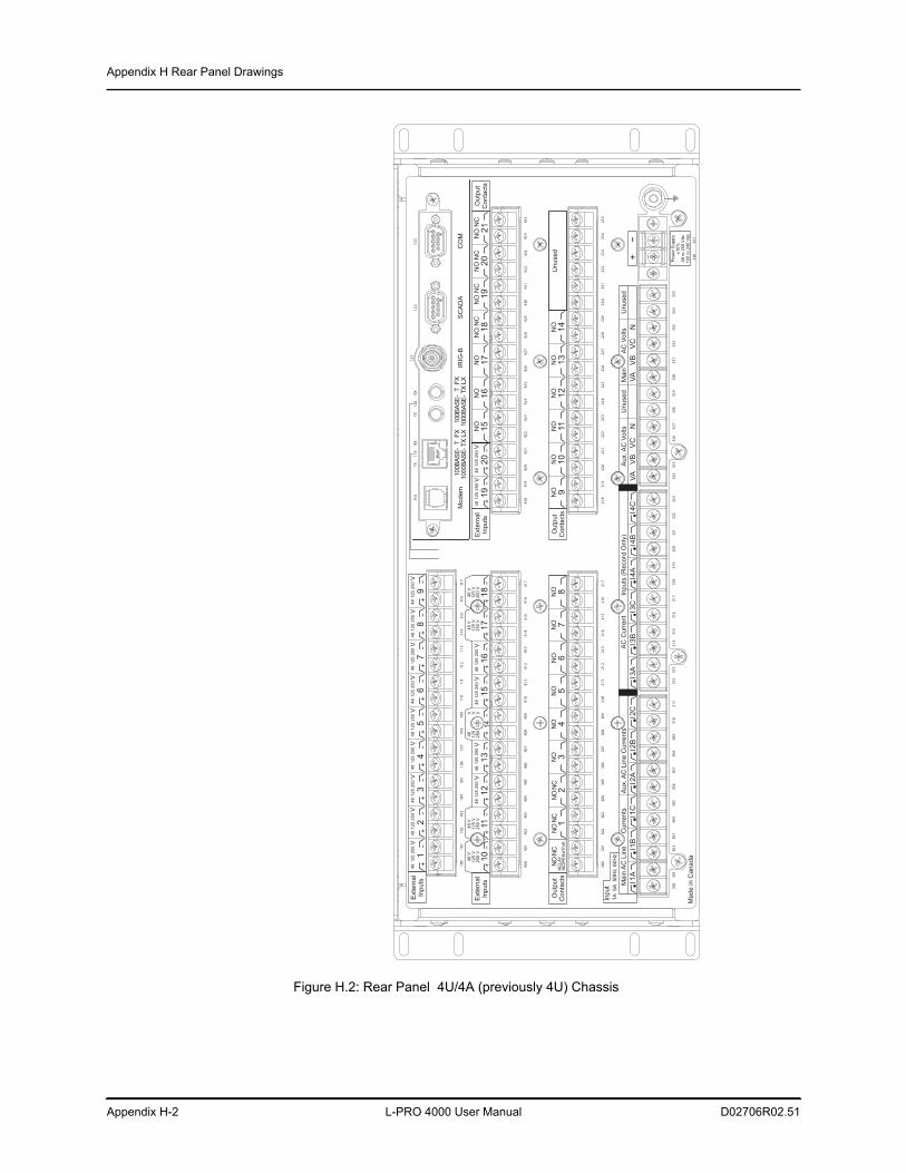
Appendix H Rear Panel Drawings
Appendix H-2 L-PRO 4000 User Manual D02706R02.51
Figure H.2: Rear Panel 4U/4A (previously 4U) Chassis
Pow
er
Supply
±10%
48 to 2
50 V
dc
100 to 2
40 V
ac
I1A
I2A
I3A
I4A
I1B
I2B
I3B
I4B
I1C
I2C
I3C
I4C
Inp
ut
1A
50
Hz
5A
60
Hz
Ma
inA
C L
ine
C
urr
en
tsA
C C
urr
en
t In
pu
ts (
Re
co
rd O
nly
)A
ux.A
C L
ine
Cu
rre
nts
300
312
324
301
313
325
302
314
326
303
315
327
304
316
328
305
317
329
306
318
330
307
319
331
308
320
332
309
321
333
310
322
334
336
311
323
335
337
VA
VA
VB
VB
VC
VC
NN
Au
x.A
C V
olts
Ma
inA
C V
olts
Un
use
dU
nu
se
d
Ma
de
in
Ca
na
da
Un
use
d
200
218
201
219
202
220
203
221
204
222
205
223
206
224
207
225
208
226
209
227
210
228
211
229
212
230
213
231
214
232
215
233
216
234
217
235
RE
LA
YIN
OP
ER
AT
IVE
NC
NO
NC
NO
NC
NO
NO
NO
NO
NO
NO
NO
NO
NO
NO
NO
NO
NO
Ou
tpu
tC
on
tacts
Ou
tpu
tC
on
tacts
67
81
23
49
10
11
12
13
14
5
19
20
10
11
12
13
14
15
16
17
18
NO
NO
NO
NO
NC
NO
NC
NO
NC
NO
NC
Ou
tpu
tC
on
tacts
16
15
17
18
19
20
21
Exte
rna
lIn
pu
tsE
xte
rna
lIn
pu
ts
400
418
401
419
402
420
403
421
404
422
405
423
406
424
407
425
408
426
409
427
410
428
411
429
412
430
413
431
414
432
415
433
416
434
417
435
48
12
52
50
V4
81
25
25
0V
48
125
250
V48
125
250
V48
125
250
V48
125
250
V
48 V
12
5 V
25
0 V
48 V
125 V
250 V
48 V
125 V
250 V
48
V125 V
250 V
48
V V125
V250
12
34
56
78
9E
xte
rna
lIn
pu
ts
100
101
102
103
104
105
106
107
108
109
110
111
112
113
114
115
116
117
48
125
250
V48
125
250
V48
125
250
V48
125
250
V48
125
250
V48
125
250
V48
125
250
V48
125
250
V48
125
250
V
Mo
de
mIR
IG-B
SC
AD
AC
OM
100B
AS
E-
1000B
AS
E-
FX
TLX
TX
100B
AS
E-
1000B
AS
E-
FX
TLX
TX
RXRX
TXTX
118
119
120
121
122
123
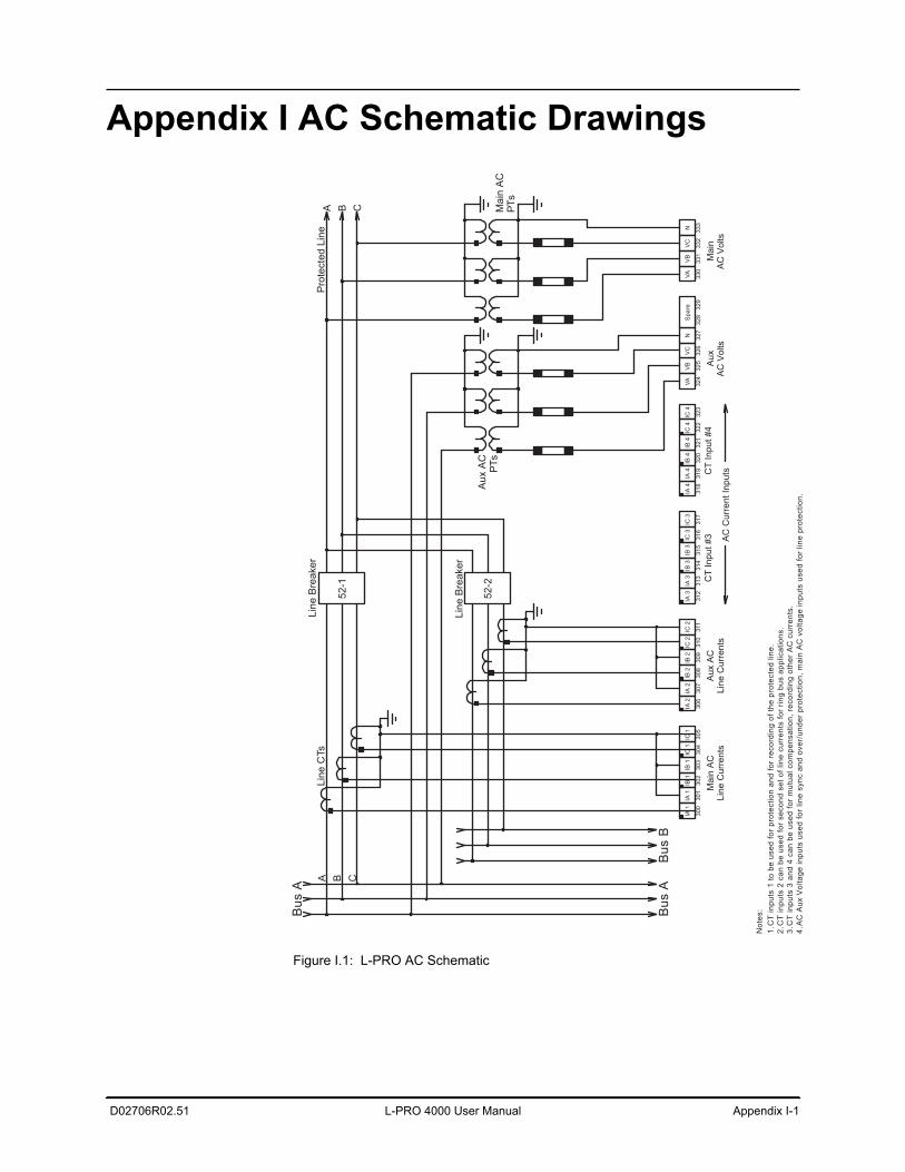
D02706R02.51 L-PRO 4000 User Manual Appendix I-1
Appendix I AC Schematic Drawings
Figure I.1: L-PRO AC Schematic
AC
Aux
Vol
tage
inpu
ts u
sed
for
line
sync
and
ove
r/un
der
prot
ectio
n, m
ain
AC
vol
tage
inpu
ts u
sed
for
line
prot
ectio
n.4.
CT
inpu
ts 3
and
4 c
an b
e us
ed fo
r m
utua
l com
pens
atio
n, r
ecor
ding
oth
er A
C c
urre
nts.
3.C
T in
puts
2 c
an b
e us
ed fo
r se
cond
set
of l
ine
curr
ents
for
ring
bus
appl
icat
ions
.2.
CT
inpu
ts 1
to b
e us
ed fo
r pr
otec
tion
and
for
reco
rdin
g of
the
prot
ecte
d lin
e.1.N
otes
:
A B C
Line
CTs
Line
Bre
aker
52-1
Pro
tect
ed L
ine
IA 1
300
IA 1
301
IB 1
302
IB 1
303
IC 1
304
IC 1
305
IA 2
306
IA 2
307
IB 2
308
IB 2
309
IC 2
310
IC 2
311
IA 3
312
IA 3
313
IB 3
314
IB 3
315
IC 3
316
IC 3
317
IA 4
318
IA 4
319
IB 4
320
IB 4
321
IC 4
322
IC 4
323
VA 324
VB 325
VC
326
N 327
328Spa
re 329
VA 330
VB 331
VC
332
N 333
Mai
nAC
Vol
tsA
ux A
CLi
ne C
urre
nts
CT
Inpu
t #3
Mai
n A
CLi
ne C
urre
nts
CT
Inpu
t #4
Aux
AC
PTs
Mai
n A
CPT
s
Line
Bre
aker
52-2
Aux
AC V
olts
AC
Cur
rent
Inpu
ts
Bus
A
A B C
Bus
B
Bus
A

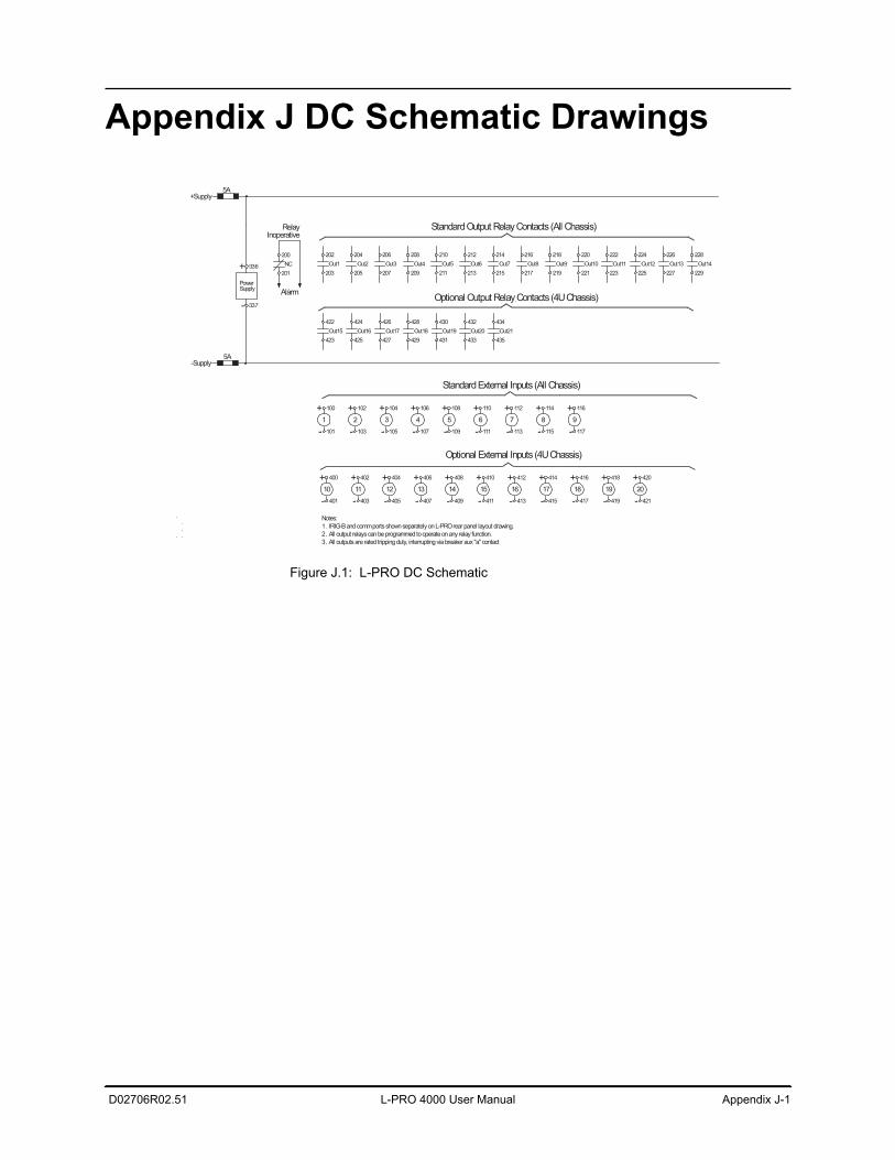
D02706R02.51 L-PRO 4000 User Manual Appendix J-1
Appendix J DC Schematic Drawings
Figure J.1: L-PRO DC Schematic
Standard External Inputs (All Chassis)
Standard Output Relay Contacts (All Chassis)
-
104
105
Notes: 1. IRIG-B and comm ports shown separately on L-PRO rear panel layout drawing.2. All output relays can be programmed to operate on any relay function.3. All outputs are rated tripping duty, interrupting via breaker aux "a" contact
-Supply
1
- 101
+ 100
2
- 103
+ 102
3
-
+
337
+
-
106
107
4
-
+5
-
+6
109 -
108 +
111
110
7113
112
8115-
114+9
- 117
+ 116
10
- 401
+ 400
+Supply
Inoperative
AlarmPower
+
Supply
336
5A
201 203
200NC
Relay
Out1202
205 207Out2
204 206Out3
209 211
208Out4
210Out5
213 215
212Out6
214Out7
217 219
216Out8
218Out9
14
404
405
402
403
11
-
+12
-
+13
-
+
407 -
406 + +
409
408
15411-
410
16413-
412+17
- 415
+ 414 418
419
416
417
18
-
+19
-
+ 420
421
20
-
+
Out17
Out13Out11221 223Out10
220 222
225 227Out12
224 226
Out15
229
423
Out14228
422
425 427Out16
424 426Out21Out19
429 431Out18
428 430
433 435Out20
432 434
Optional External Inputs (4U Chassis)
Optional Output Relay Contacts (4U Chassis)
5A


D02706R02.51 L-PRO 4000 User Manual Appendix K-1
Appendix K Function Logic DiagramDiagram in plastic sleeve.

D02706R02.51 L-PRO 4000 User Manual Appendix L-1
Appendix L L-PRO Setting ExampleProtection, Timers and I/O Status
The relay does not block any protection functions or external inputs during the setting save or active group change, but the external output contacts are reset for one cycle.
The relay applies the setting parameters, resets all protection functions, resets all timers and continues to process the protection algorithms but does not apply any action to the output contacts for one cycle. For close-in (heavy) fault con-ditions that occur at the time of a setting change the relay performance has a maximum increase in output delay of one cycle. For light fault conditions the relay performance does not have a noticeable change. There is normally a one cycle decision making process of operating time. When the relay algorithms determine that a fault is present, tripping will occur after a one cycle delay. It will take an additional 3 ms to actually close the output tripping contacts.
Latch Status The relay does not reset any ProLogic, Group Logic or Virtual Input latch func-tions during the setting save or active group change. Retaining latch status al-lows the relay continuous access to specific latched logic states. This is useful when the relay has ProLogic, Group Logic or Virtual Input functions used to block protection or ancillary functions for specific operating conditions.
Event Status Reset
The relay resets all the events that are currently high and reports states of all the events that remain high after a setting change.
Viewing Active Setting Group
To view the active setting group and status of the group logic functions in real time via the TUI, enter the Metering/Logic/Setting Group menu choice. To view a snapshot of the group logic data, enter the Settings/Active Group menu choice.
Front Panel Active Setting Group
The front panel display along with the front panel control buttons allow the user to access metering and setting functions within the relay.
The front display also allows the user to reset the LED target lights that will occur if a relay trip occurs. The front display will go dark and reset if no user interaction has taken place for a period of time. Pressing any of the front panel control buttons brings the front panel to life.
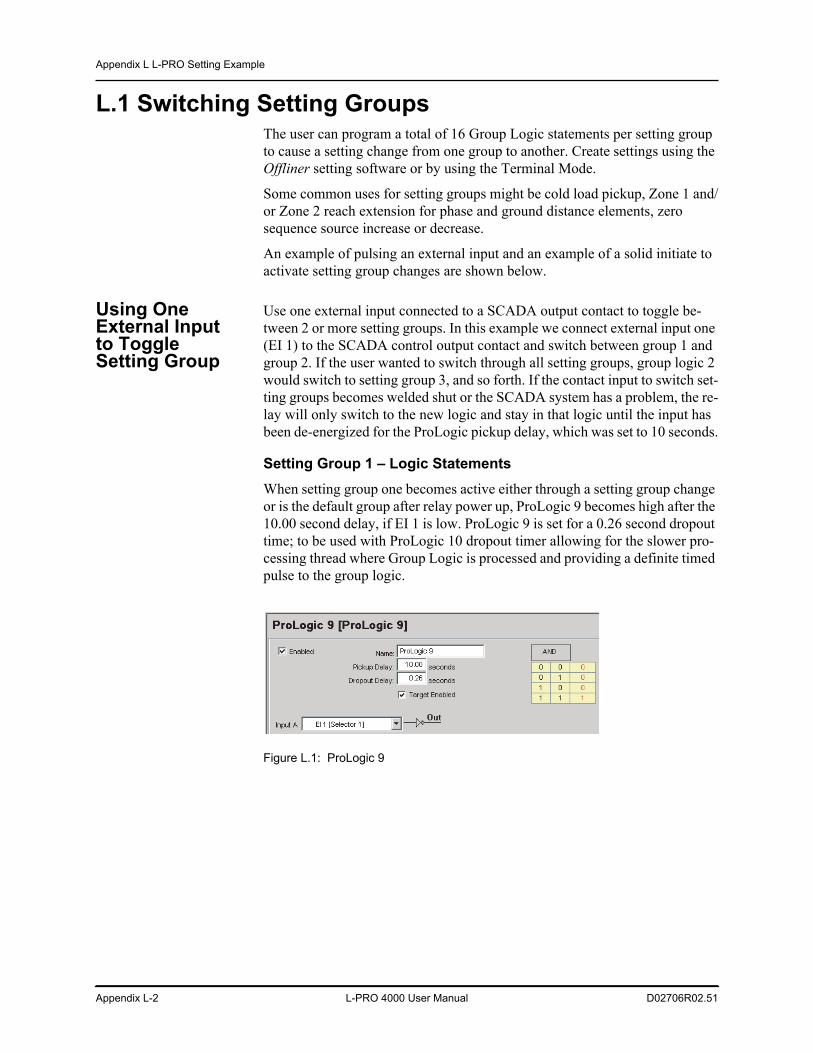
Appendix L L-PRO Setting Example
Appendix L-2 L-PRO 4000 User Manual D02706R02.51
L.1 Switching Setting GroupsThe user can program a total of 16 Group Logic statements per setting group to cause a setting change from one group to another. Create settings using the Offliner setting software or by using the Terminal Mode.
Some common uses for setting groups might be cold load pickup, Zone 1 and/or Zone 2 reach extension for phase and ground distance elements, zero sequence source increase or decrease.
An example of pulsing an external input and an example of a solid initiate to activate setting group changes are shown below.
Using One External Input to Toggle Setting Group
Use one external input connected to a SCADA output contact to toggle be-tween 2 or more setting groups. In this example we connect external input one (EI 1) to the SCADA control output contact and switch between group 1 and group 2. If the user wanted to switch through all setting groups, group logic 2 would switch to setting group 3, and so forth. If the contact input to switch set-ting groups becomes welded shut or the SCADA system has a problem, the re-lay will only switch to the new logic and stay in that logic until the input has been de-energized for the ProLogic pickup delay, which was set to 10 seconds.
Setting Group 1 – Logic StatementsWhen setting group one becomes active either through a setting group change or is the default group after relay power up, ProLogic 9 becomes high after the 10.00 second delay, if EI 1 is low. ProLogic 9 is set for a 0.26 second dropout time; to be used with ProLogic 10 dropout timer allowing for the slower pro-cessing thread where Group Logic is processed and providing a definite timed pulse to the group logic.
Figure L.1: ProLogic 9
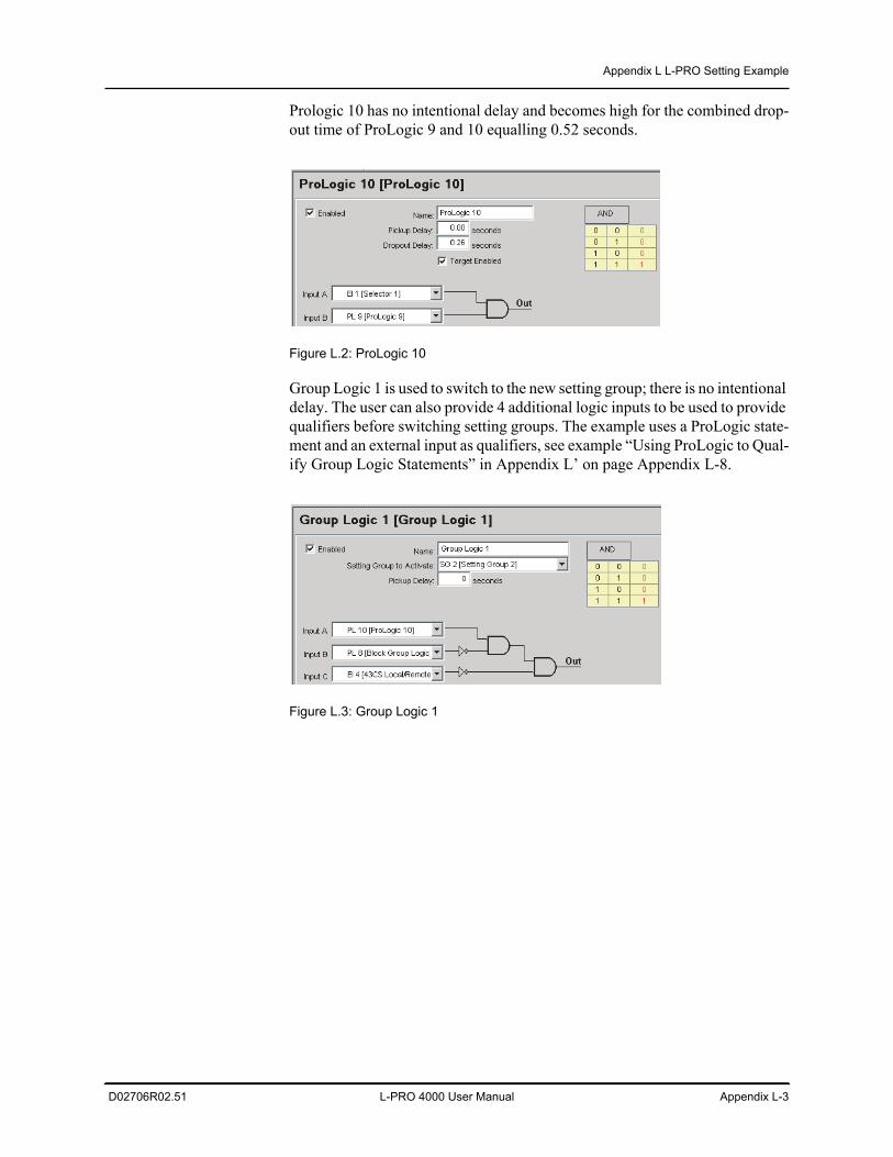
Appendix L L-PRO Setting Example
D02706R02.51 L-PRO 4000 User Manual Appendix L-3
Prologic 10 has no intentional delay and becomes high for the combined drop-out time of ProLogic 9 and 10 equalling 0.52 seconds.
Figure L.2: ProLogic 10
Group Logic 1 is used to switch to the new setting group; there is no intentional delay. The user can also provide 4 additional logic inputs to be used to provide qualifiers before switching setting groups. The example uses a ProLogic state-ment and an external input as qualifiers, see example “Using ProLogic to Qual-ify Group Logic Statements” in Appendix L’ on page Appendix L-8.
Figure L.3: Group Logic 1
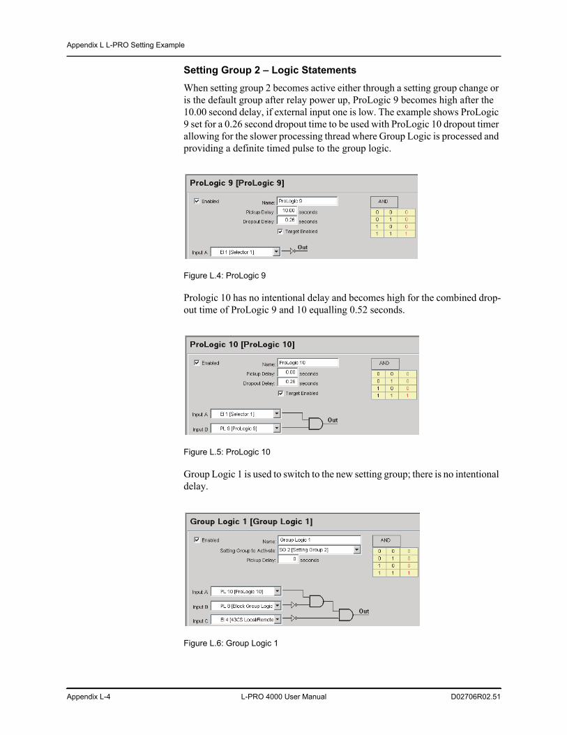
Appendix L L-PRO Setting Example
Appendix L-4 L-PRO 4000 User Manual D02706R02.51
Setting Group 2 – Logic StatementsWhen setting group 2 becomes active either through a setting group change or is the default group after relay power up, ProLogic 9 becomes high after the 10.00 second delay, if external input one is low. The example shows ProLogic 9 set for a 0.26 second dropout time to be used with ProLogic 10 dropout timer allowing for the slower processing thread where Group Logic is processed and providing a definite timed pulse to the group logic.
Figure L.4: ProLogic 9
Prologic 10 has no intentional delay and becomes high for the combined drop-out time of ProLogic 9 and 10 equalling 0.52 seconds.
Figure L.5: ProLogic 10
Group Logic 1 is used to switch to the new setting group; there is no intentional delay.
Figure L.6: Group Logic 1
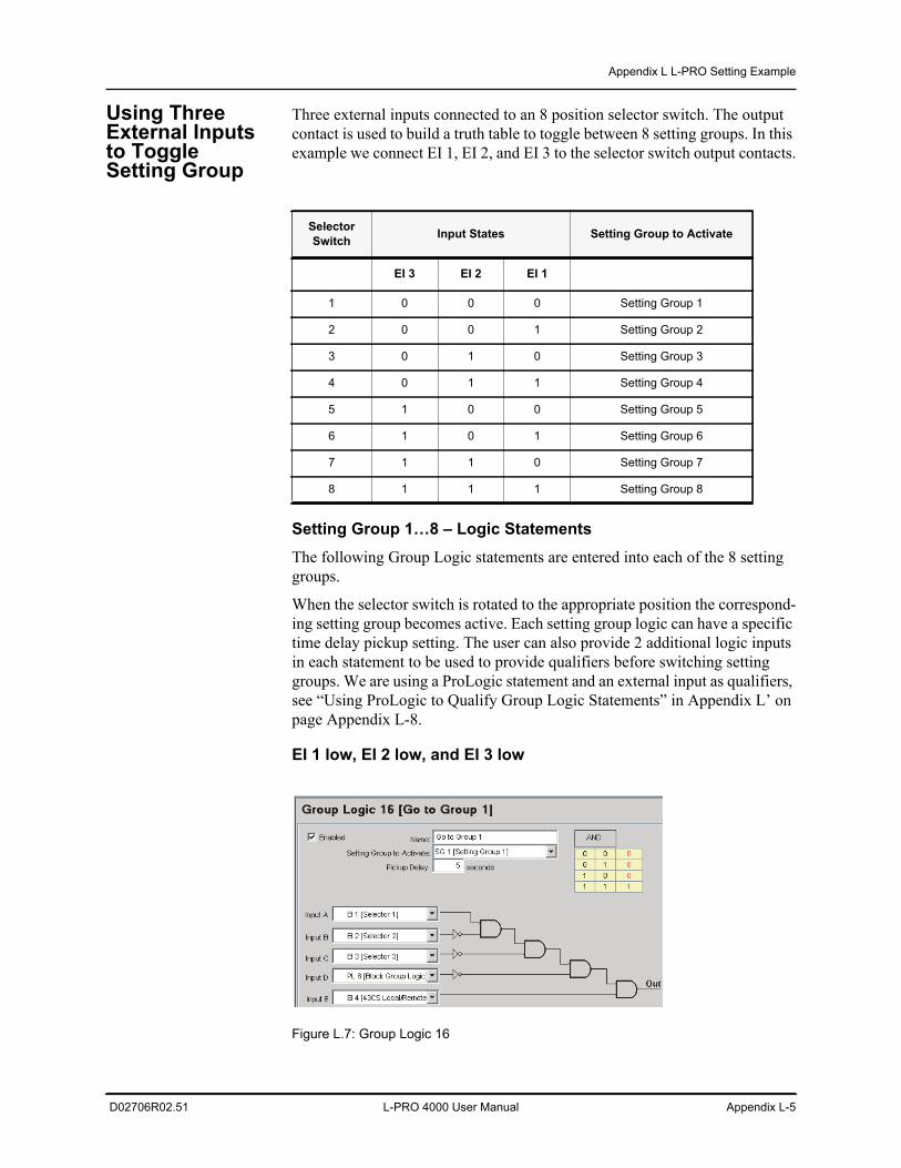
Appendix L L-PRO Setting Example
D02706R02.51 L-PRO 4000 User Manual Appendix L-5
Using Three External Inputs to Toggle Setting Group
Three external inputs connected to an 8 position selector switch. The output contact is used to build a truth table to toggle between 8 setting groups. In this example we connect EI 1, EI 2, and EI 3 to the selector switch output contacts.
Setting Group 1…8 – Logic StatementsThe following Group Logic statements are entered into each of the 8 setting groups.
When the selector switch is rotated to the appropriate position the correspond-ing setting group becomes active. Each setting group logic can have a specific time delay pickup setting. The user can also provide 2 additional logic inputs in each statement to be used to provide qualifiers before switching setting groups. We are using a ProLogic statement and an external input as qualifiers, see “Using ProLogic to Qualify Group Logic Statements” in Appendix L’ on page Appendix L-8.
EI 1 low, EI 2 low, and EI 3 low
Figure L.7: Group Logic 16
Selector Switch Input States Setting Group to Activate
EI 3 EI 2 EI 1
1 0 0 0 Setting Group 1
2 0 0 1 Setting Group 2
3 0 1 0 Setting Group 3
4 0 1 1 Setting Group 4
5 1 0 0 Setting Group 5
6 1 0 1 Setting Group 6
7 1 1 0 Setting Group 7
8 1 1 1 Setting Group 8
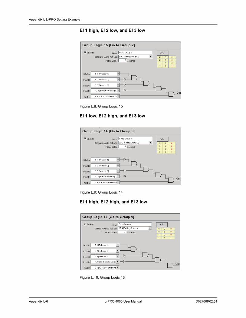
Appendix L L-PRO Setting Example
Appendix L-6 L-PRO 4000 User Manual D02706R02.51
EI 1 high, EI 2 low, and EI 3 low
Figure L.8: Group Logic 15
EI 1 low, EI 2 high, and EI 3 low
Figure L.9: Group Logic 14
EI 1 high, EI 2 high, and EI 3 low
Figure L.10: Group Logic 13
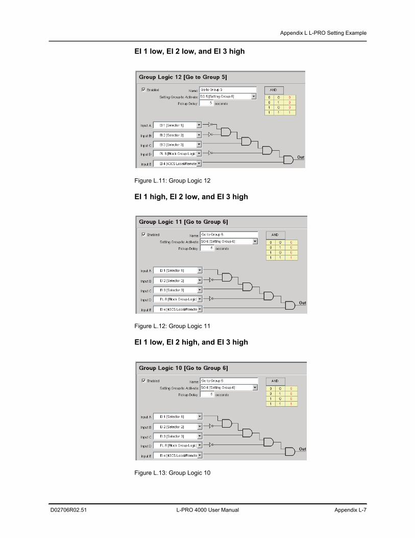
Appendix L L-PRO Setting Example
D02706R02.51 L-PRO 4000 User Manual Appendix L-7
EI 1 low, EI 2 low, and EI 3 high
Figure L.11: Group Logic 12
EI 1 high, EI 2 low, and EI 3 high
Figure L.12: Group Logic 11
EI 1 low, EI 2 high, and EI 3 high
Figure L.13: Group Logic 10
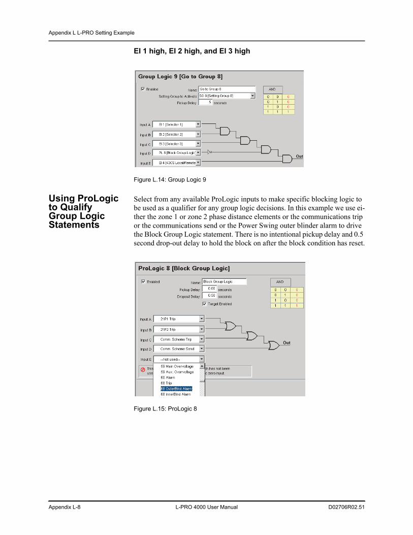
Appendix L L-PRO Setting Example
Appendix L-8 L-PRO 4000 User Manual D02706R02.51
EI 1 high, EI 2 high, and EI 3 high
Figure L.14: Group Logic 9
Using ProLogic to Qualify Group Logic Statements
Select from any available ProLogic inputs to make specific blocking logic to be used as a qualifier for any group logic decisions. In this example we use ei-ther the zone 1 or zone 2 phase distance elements or the communications trip or the communications send or the Power Swing outer blinder alarm to drive the Block Group Logic statement. There is no intentional pickup delay and 0.5 second drop-out delay to hold the block on after the block condition has reset.
Figure L.15: ProLogic 8
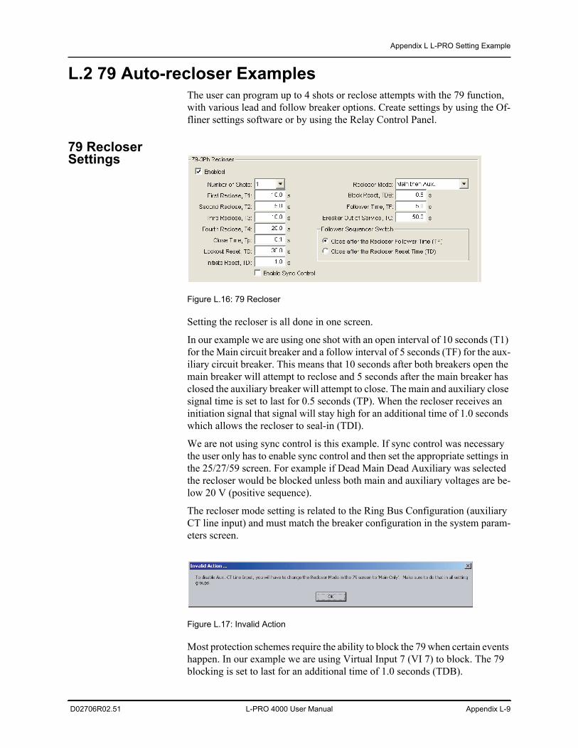
Appendix L L-PRO Setting Example
D02706R02.51 L-PRO 4000 User Manual Appendix L-9
L.2 79 Auto-recloser ExamplesThe user can program up to 4 shots or reclose attempts with the 79 function, with various lead and follow breaker options. Create settings by using the Of-fliner settings software or by using the Relay Control Panel.
79 Recloser Settings
Figure L.16: 79 Recloser
Setting the recloser is all done in one screen.
In our example we are using one shot with an open interval of 10 seconds (T1) for the Main circuit breaker and a follow interval of 5 seconds (TF) for the aux-iliary circuit breaker. This means that 10 seconds after both breakers open the main breaker will attempt to reclose and 5 seconds after the main breaker has closed the auxiliary breaker will attempt to close. The main and auxiliary close signal time is set to last for 0.5 seconds (TP). When the recloser receives an initiation signal that signal will stay high for an additional time of 1.0 seconds which allows the recloser to seal-in (TDI).
We are not using sync control is this example. If sync control was necessary the user only has to enable sync control and then set the appropriate settings in the 25/27/59 screen. For example if Dead Main Dead Auxiliary was selected the recloser would be blocked unless both main and auxiliary voltages are be-low 20 V (positive sequence).
The recloser mode setting is related to the Ring Bus Configuration (auxiliary CT line input) and must match the breaker configuration in the system param-eters screen.
Figure L.17: Invalid Action
Most protection schemes require the ability to block the 79 when certain events happen. In our example we are using Virtual Input 7 (VI 7) to block. The 79 blocking is set to last for an additional time of 1.0 seconds (TDB).
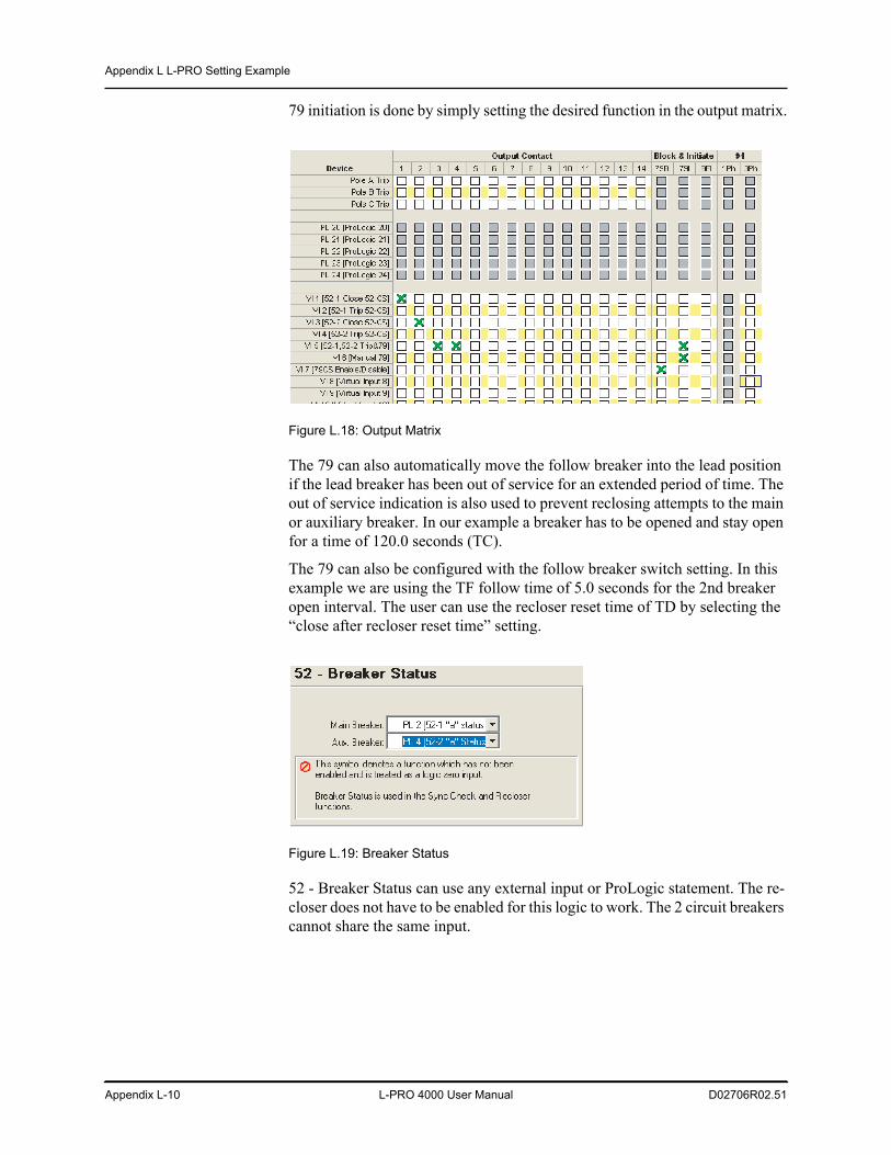
Appendix L L-PRO Setting Example
Appendix L-10 L-PRO 4000 User Manual D02706R02.51
79 initiation is done by simply setting the desired function in the output matrix.
Figure L.18: Output Matrix
The 79 can also automatically move the follow breaker into the lead position if the lead breaker has been out of service for an extended period of time. The out of service indication is also used to prevent reclosing attempts to the main or auxiliary breaker. In our example a breaker has to be opened and stay open for a time of 120.0 seconds (TC).
The 79 can also be configured with the follow breaker switch setting. In this example we are using the TF follow time of 5.0 seconds for the 2nd breaker open interval. The user can use the recloser reset time of TD by selecting the “close after recloser reset time” setting.
Figure L.19: Breaker Status
52 - Breaker Status can use any external input or ProLogic statement. The re-closer does not have to be enabled for this logic to work. The 2 circuit breakers cannot share the same input.
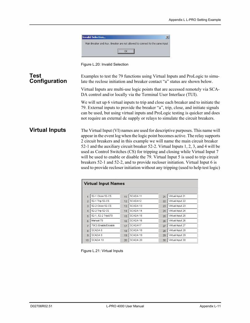
Appendix L L-PRO Setting Example
D02706R02.51 L-PRO 4000 User Manual Appendix L-11
Figure L.20: Invalid Selection
Test Configuration
Examples to test the 79 functions using Virtual Inputs and ProLogic to simu-late the reclose initiation and breaker contact “a” status are shown below.
Virtual Inputs are multi-use logic points that are accessed remotely via SCA-DA control and/or locally via the Terminal User Interface (TUI).
We will set up 6 virtual inputs to trip and close each breaker and to initiate the 79. External inputs to provide the breaker “a”, trip, close, and initiate signals can be used, but using virtual inputs and ProLogic testing is quicker and does not require an external dc supply or relays to simulate the circuit breakers.
Virtual Inputs The Virtual Input (VI) names are used for descriptive purposes. This name will appear in the event log when the logic point becomes active. The relay supports 2 circuit breakers and in this example we will name the main circuit breaker 52-1 and the auxiliary circuit breaker 52-2. Virtual Inputs 1, 2, 3, and 4 will be used as Control Switches (CS) for tripping and closing while Virtual Input 7 will be used to enable or disable the 79. Virtual Input 5 is used to trip circuit breakers 52-1 and 52-2, and to provide recloser initiation. Virtual Input 6 is used to provide recloser initiation without any tripping (used to help test logic)
Figure L.21: Virtual Inputs
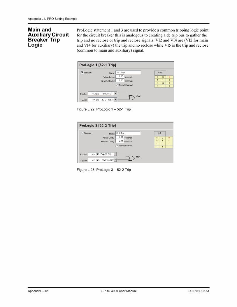
Appendix L L-PRO Setting Example
Appendix L-12 L-PRO 4000 User Manual D02706R02.51
Main and Auxiliary Circuit Breaker Trip Logic
ProLogic statement 1 and 3 are used to provide a common tripping logic point for the circuit breaker this is analogous to creating a dc trip bus to gather the trip and no reclose or trip and reclose signals. VI2 and VI4 are (VI2 for main and VI4 for auxiliary) the trip and no reclose while VI5 is the trip and reclose (common to main and auxiliary) signal.
Figure L.22: ProLogic 1 – 52-1 Trip
Figure L.23: ProLogic 3 – 52-2 Trip
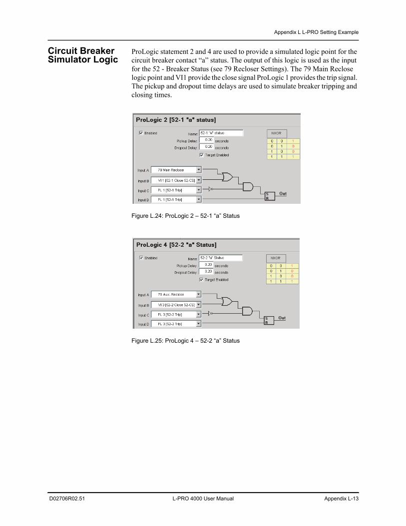
Appendix L L-PRO Setting Example
D02706R02.51 L-PRO 4000 User Manual Appendix L-13
Circuit Breaker Simulator Logic
ProLogic statement 2 and 4 are used to provide a simulated logic point for the circuit breaker contact “a” status. The output of this logic is used as the input for the 52 - Breaker Status (see 79 Recloser Settings). The 79 Main Reclose logic point and VI1 provide the close signal ProLogic 1 provides the trip signal. The pickup and dropout time delays are used to simulate breaker tripping and closing times.
Figure L.24: ProLogic 2 – 52-1 “a” Status
Figure L.25: ProLogic 4 – 52-2 “a” Status
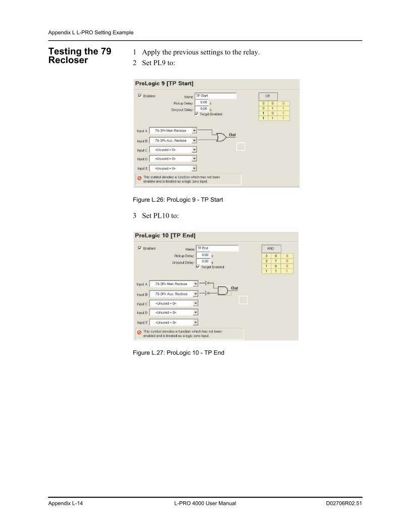
Appendix L L-PRO Setting Example
Appendix L-14 L-PRO 4000 User Manual D02706R02.51
Testing the 79 Recloser
1 Apply the previous settings to the relay.2 Set PL9 to:
Figure L.26: ProLogic 9 - TP Start
3 Set PL10 to:
Figure L.27: ProLogic 10 - TP End
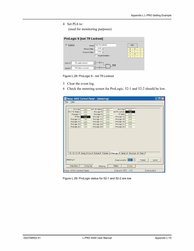
Appendix L L-PRO Setting Example
D02706R02.51 L-PRO 4000 User Manual Appendix L-15
4 Set PL6 to: (used for monitoring purposes)
Figure L.28: ProLogic 6 - not 79 Lockout
5 Clear the event log.6 Check the metering screen for ProLogic. 52-1 and 52-2 should be low.
Figure L.29: ProLogic status for 52-1 and 52-2 are low
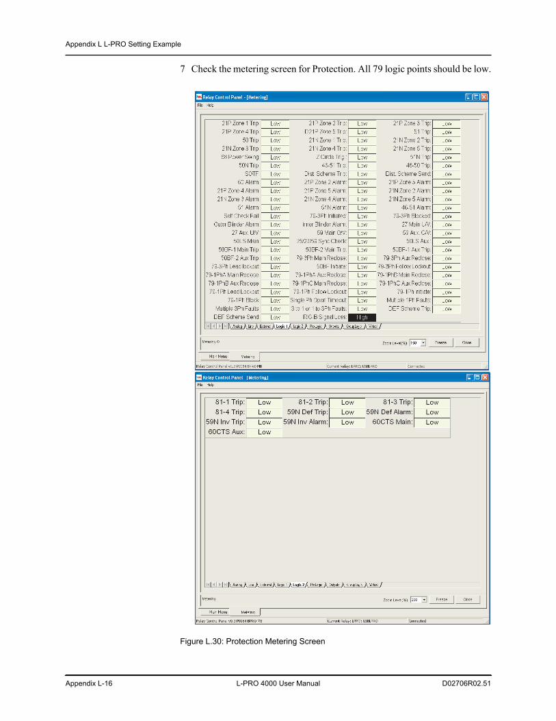
Appendix L L-PRO Setting Example
Appendix L-16 L-PRO 4000 User Manual D02706R02.51
7 Check the metering screen for Protection. All 79 logic points should be low.
Figure L.30: Protection Metering Screen
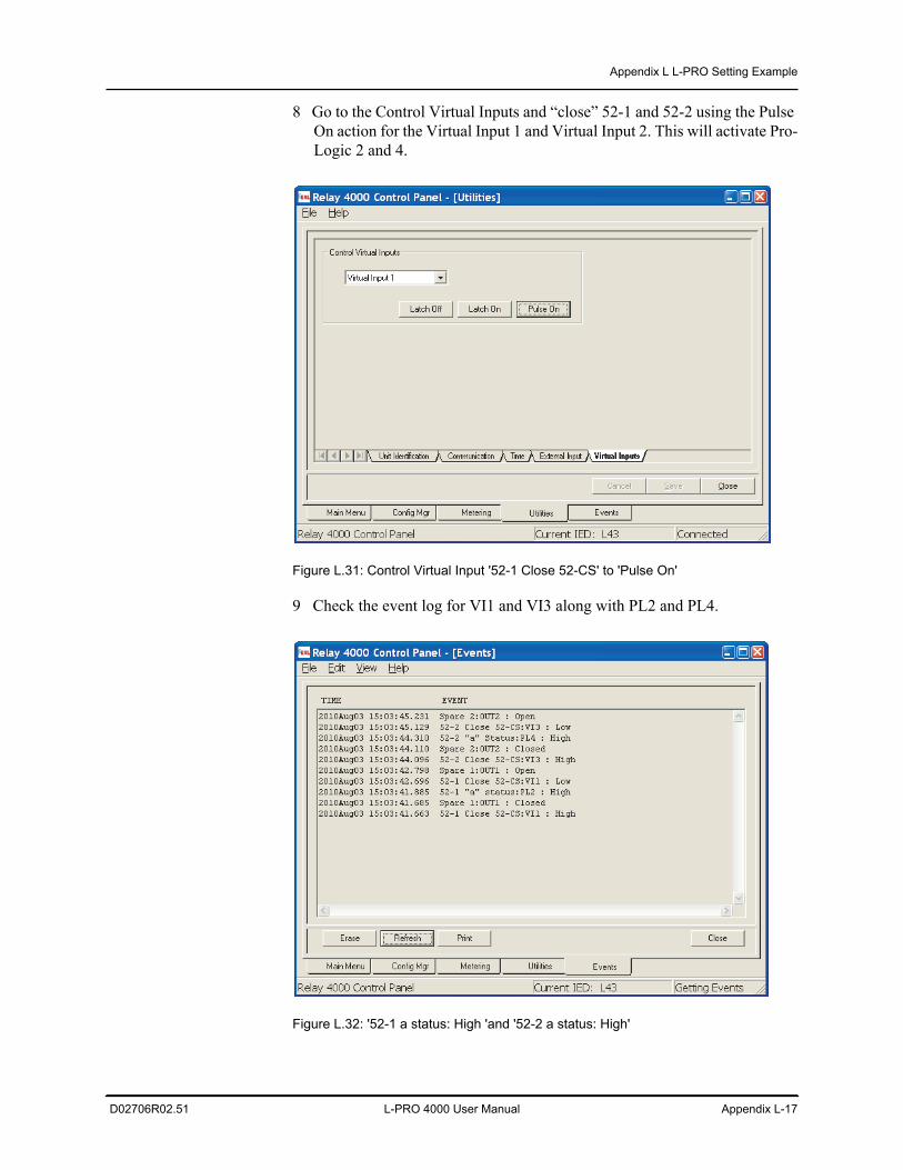
Appendix L L-PRO Setting Example
D02706R02.51 L-PRO 4000 User Manual Appendix L-17
8 Go to the Control Virtual Inputs and “close” 52-1 and 52-2 using the Pulse On action for the Virtual Input 1 and Virtual Input 2. This will activate Pro-Logic 2 and 4.
Figure L.31: Control Virtual Input '52-1 Close 52-CS' to 'Pulse On'
9 Check the event log for VI1 and VI3 along with PL2 and PL4.
Figure L.32: '52-1 a status: High 'and '52-2 a status: High'
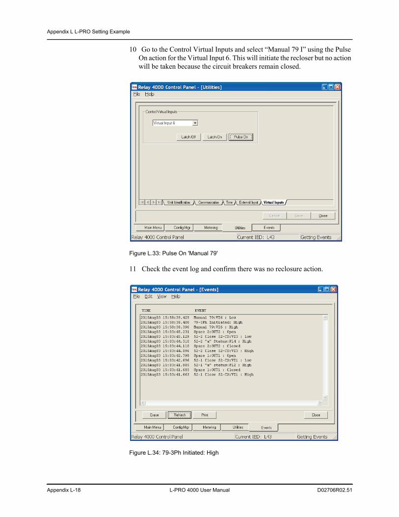
Appendix L L-PRO Setting Example
Appendix L-18 L-PRO 4000 User Manual D02706R02.51
10 Go to the Control Virtual Inputs and select “Manual 79 I” using the Pulse On action for the Virtual Input 6. This will initiate the recloser but no action will be taken because the circuit breakers remain closed.
Figure L.33: Pulse On 'Manual 79'
11 Check the event log and confirm there was no reclosure action.
Figure L.34: 79-3Ph Initiated: High
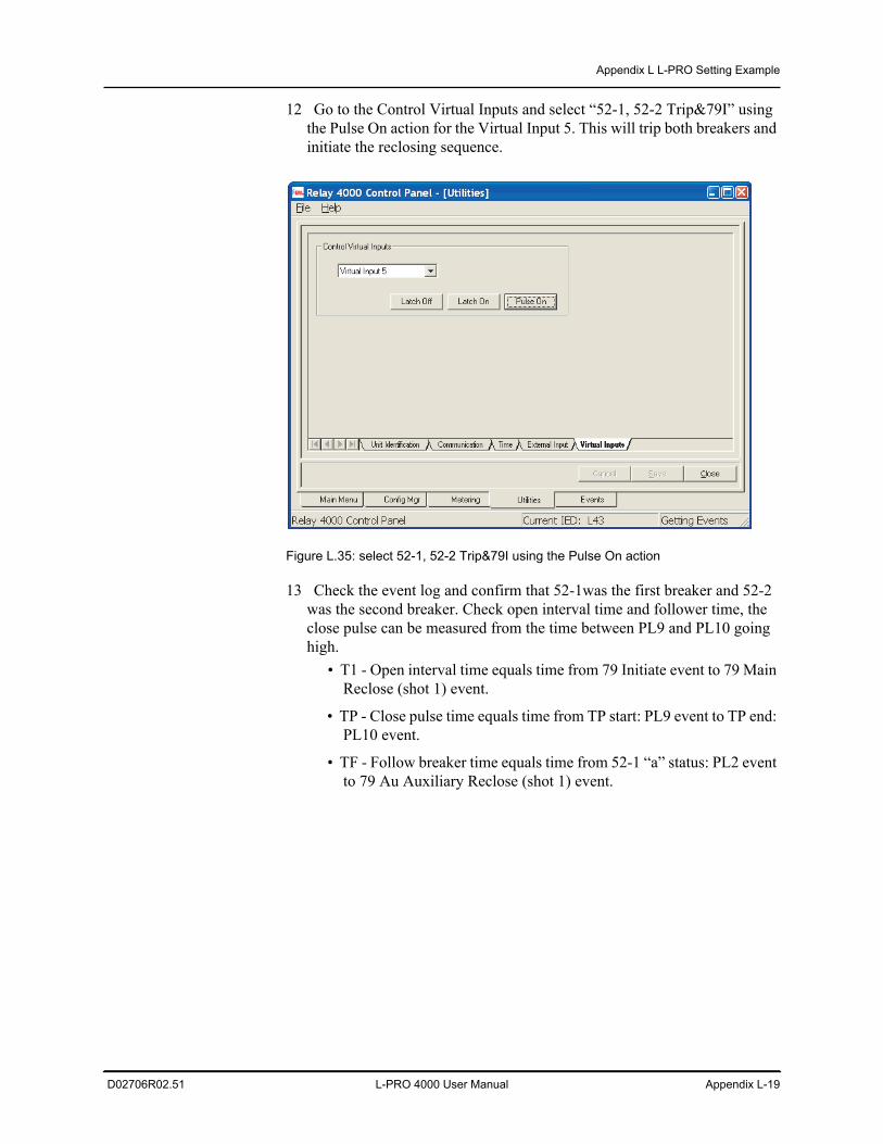
Appendix L L-PRO Setting Example
D02706R02.51 L-PRO 4000 User Manual Appendix L-19
12 Go to the Control Virtual Inputs and select “52-1, 52-2 Trip&79I” using the Pulse On action for the Virtual Input 5. This will trip both breakers and initiate the reclosing sequence.
Figure L.35: select 52-1, 52-2 Trip&79I using the Pulse On action
13 Check the event log and confirm that 52-1was the first breaker and 52-2 was the second breaker. Check open interval time and follower time, the close pulse can be measured from the time between PL9 and PL10 going high.
• T1 - Open interval time equals time from 79 Initiate event to 79 Main Reclose (shot 1) event.
• TP - Close pulse time equals time from TP start: PL9 event to TP end: PL10 event.
• TF - Follow breaker time equals time from 52-1 “a” status: PL2 event to 79 Au Auxiliary Reclose (shot 1) event.
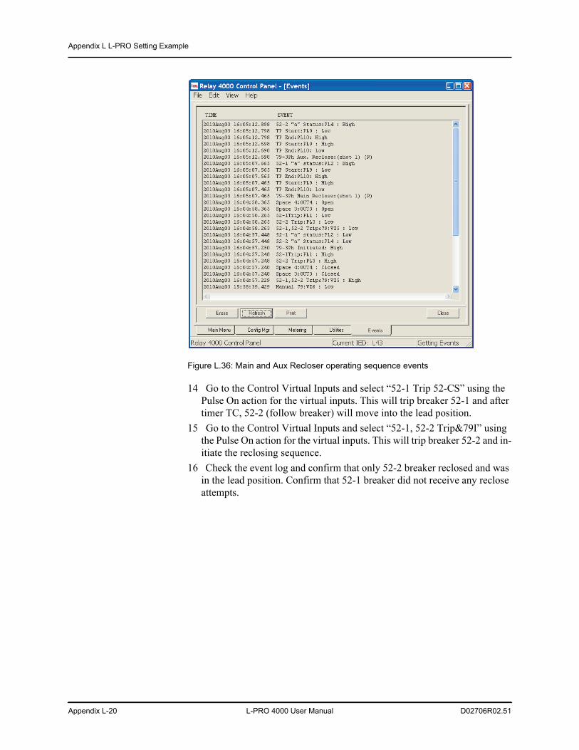
Appendix L L-PRO Setting Example
Appendix L-20 L-PRO 4000 User Manual D02706R02.51
Figure L.36: Main and Aux Recloser operating sequence events
14 Go to the Control Virtual Inputs and select “52-1 Trip 52-CS” using the Pulse On action for the virtual inputs. This will trip breaker 52-1 and after timer TC, 52-2 (follow breaker) will move into the lead position.
15 Go to the Control Virtual Inputs and select “52-1, 52-2 Trip&79I” using the Pulse On action for the virtual inputs. This will trip breaker 52-2 and in-itiate the reclosing sequence.
16 Check the event log and confirm that only 52-2 breaker reclosed and was in the lead position. Confirm that 52-1 breaker did not receive any reclose attempts.
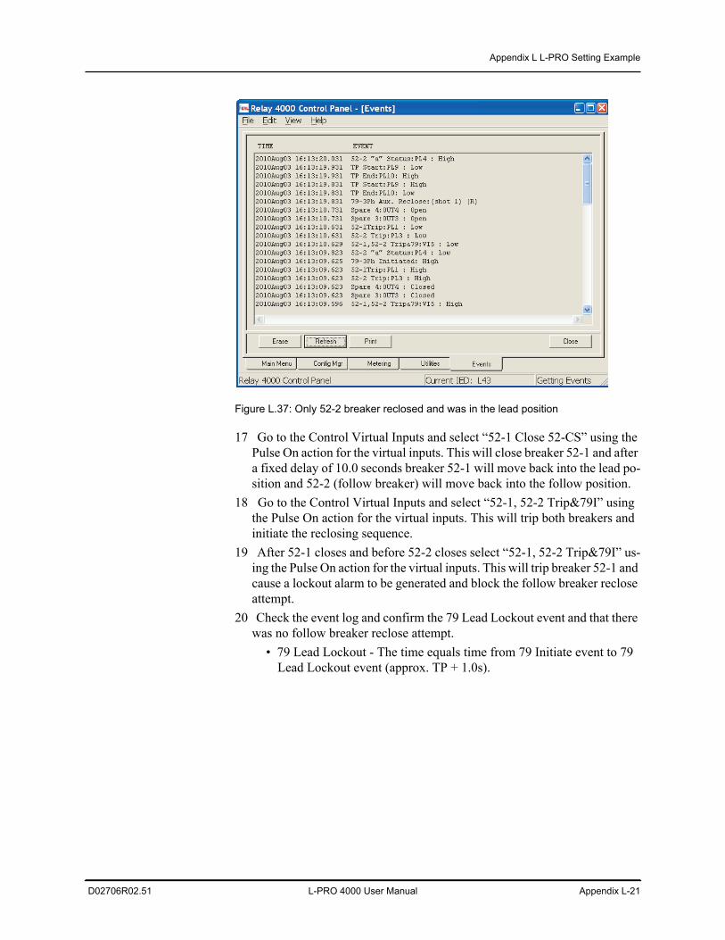
Appendix L L-PRO Setting Example
D02706R02.51 L-PRO 4000 User Manual Appendix L-21
Figure L.37: Only 52-2 breaker reclosed and was in the lead position
17 Go to the Control Virtual Inputs and select “52-1 Close 52-CS” using the Pulse On action for the virtual inputs. This will close breaker 52-1 and after a fixed delay of 10.0 seconds breaker 52-1 will move back into the lead po-sition and 52-2 (follow breaker) will move back into the follow position.
18 Go to the Control Virtual Inputs and select “52-1, 52-2 Trip&79I” using the Pulse On action for the virtual inputs. This will trip both breakers and initiate the reclosing sequence.
19 After 52-1 closes and before 52-2 closes select “52-1, 52-2 Trip&79I” us-ing the Pulse On action for the virtual inputs. This will trip breaker 52-1 and cause a lockout alarm to be generated and block the follow breaker reclose attempt.
20 Check the event log and confirm the 79 Lead Lockout event and that there was no follow breaker reclose attempt. • 79 Lead Lockout - The time equals time from 79 Initiate event to 79
Lead Lockout event (approx. TP + 1.0s).
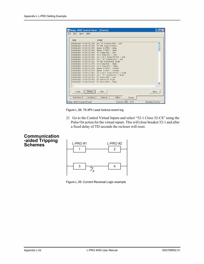
Appendix L L-PRO Setting Example
Appendix L-22 L-PRO 4000 User Manual D02706R02.51
Figure L.38: 79-3Ph Lead lockout event log
21 Go to the Control Virtual Inputs and select “52-1 Close 52-CS” using the Pulse On action for the virtual inputs. This will close breaker 52-1 and after a fixed delay of TD seconds the recloser will reset.
Communication-aided Tripping Schemes
Figure L.39: Current Reversal Logic example
1
3
2
4
L-PRO #1 L-PRO #2
F
Appendix L L-PRO Setting Example
D02706R02.51 L-PRO 4000 User Manual Appendix L-23
Current Reversal Logic Example
The relays are installed and provide line protection by the tripping Breaker #1 and Breaker #2 respectively. A ground fault occurs at location F in the parallel line. Initially, 21N2 of L-PRO #2 picks up and sends a permissive transfer trip signal to L-PRO #1. Since L-PRO #1 detects a reverse fault (21N4 picks up), it neither trips the breaker nor sends a permissive transfer trip signal. When breaker #3 opens due to a zone 1 trip, the current reversal condition occurs on L-PRO #1. If the 21P2 on L-PRO #1 operates, and if the received permissive transfer trip signal from L-PRO #2 still exists the POTT scheme on L-PRO #1 will trip breaker #1. To prevent this unwanted tripping on the parallel line, the relay has current reversal logic. The relay current reversal logic prevents the false trip during this current reversal condition. Gate #116 of the functional logic diagram and timer TL1 and TD1 stretch the zone 4 logic and block the POTT scheme from tripping the breaker or sending the transfer trip signal to the remote end.
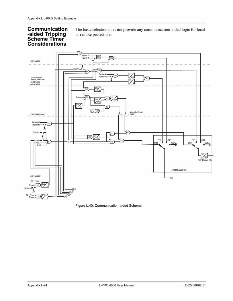
Appendix L L-PRO Setting Example
Appendix L-24 L-PRO 4000 User Manual D02706R02.51
Communication-aided Tripping Scheme Timer Considerations
The basic selection does not provide any communication-aided logic for local or remote protections.
Figure L.40: Communication-aided Scheme
PUTT SCHEME
DCB SCHEME
WEAK INFEED LOGIC
113
111
(If DCB shceme is selected, Zone 4 must be set reverse)
0
TWD33ms
TWD2
POTT SCHEME
118
117
102
104105
106
108
110
114
6ms
TWD1
TL2
0
103
0TD2
107
Receiver #1 Receiver #2
112
20ms
0
60
27 V1 59 V0
120Receiver #1 Receiver #2
(+)
51N Alarm
50N-67F 21P2
21N2
50N-67R
101
TL1
TD1116
21-4 R
21-2
21-2 119
115
Weak Infeed Enable Switch
Receiver #1 Receiver #2
(+)
POTT BASIC
SCHEME SELECTOR
PUTT
TL3, TD3 range: 0-1s
DCB
TL3
TD3
POTT BASIC
PUTTDCB
121
3I0 > Pickup
Forward
(+)
Non-directional
TCS
0
1223I0 > Pickup
Reverse TCB
0
21N4 21P4
21N2 21P2
21N1 21P1
Trip
S
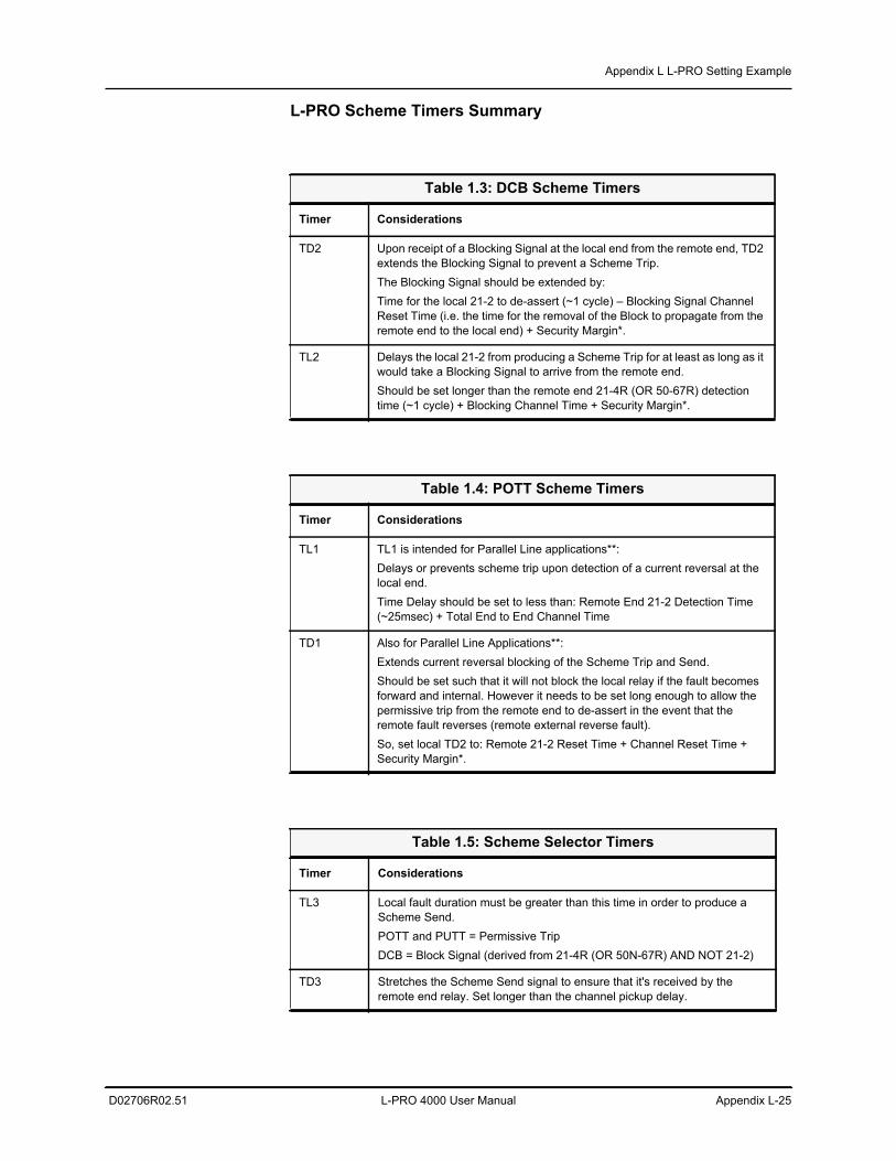
Appendix L L-PRO Setting Example
D02706R02.51 L-PRO 4000 User Manual Appendix L-25
L-PRO Scheme Timers Summary
Table 1.3: DCB Scheme Timers
Timer Considerations
TD2 Upon receipt of a Blocking Signal at the local end from the remote end, TD2 extends the Blocking Signal to prevent a Scheme Trip.The Blocking Signal should be extended by:Time for the local 21-2 to de-assert (~1 cycle) – Blocking Signal Channel Reset Time (i.e. the time for the removal of the Block to propagate from the remote end to the local end) + Security Margin*.
TL2 Delays the local 21-2 from producing a Scheme Trip for at least as long as it would take a Blocking Signal to arrive from the remote end.Should be set longer than the remote end 21-4R (OR 50-67R) detection time (~1 cycle) + Blocking Channel Time + Security Margin*.
Table 1.4: POTT Scheme Timers
Timer Considerations
TL1 TL1 is intended for Parallel Line applications**:Delays or prevents scheme trip upon detection of a current reversal at the local end. Time Delay should be set to less than: Remote End 21-2 Detection Time (~25msec) + Total End to End Channel Time
TD1 Also for Parallel Line Applications**:Extends current reversal blocking of the Scheme Trip and Send.Should be set such that it will not block the local relay if the fault becomes forward and internal. However it needs to be set long enough to allow the permissive trip from the remote end to de-assert in the event that the remote fault reverses (remote external reverse fault).So, set local TD2 to: Remote 21-2 Reset Time + Channel Reset Time + Security Margin*.
Table 1.5: Scheme Selector Timers
Timer Considerations
TL3 Local fault duration must be greater than this time in order to produce a Scheme Send.POTT and PUTT = Permissive TripDCB = Block Signal (derived from 21-4R (OR 50N-67R) AND NOT 21-2)
TD3 Stretches the Scheme Send signal to ensure that it's received by the remote end relay. Set longer than the channel pickup delay.
Appendix L L-PRO Setting Example
Appendix L-26 L-PRO 4000 User Manual D02706R02.51
Notes:* Security Margin = 0.5 to 1 cycle or a percentage of total expected time to account for errors in scheme timing assumptions.** Parallel Line applications: fault contribution can come from unfaulted line appearing as a Zone 2 fault at one end and zone 4 reverse fault at the other end. Depending on the location of the fault on the faulted line and which breaker clears first, the current may change direction and the 2 ter-minals on the unfaulted line may change state from forward to reverse and reverse to forward. The unfaulted line contribution may come either end on a networked system.
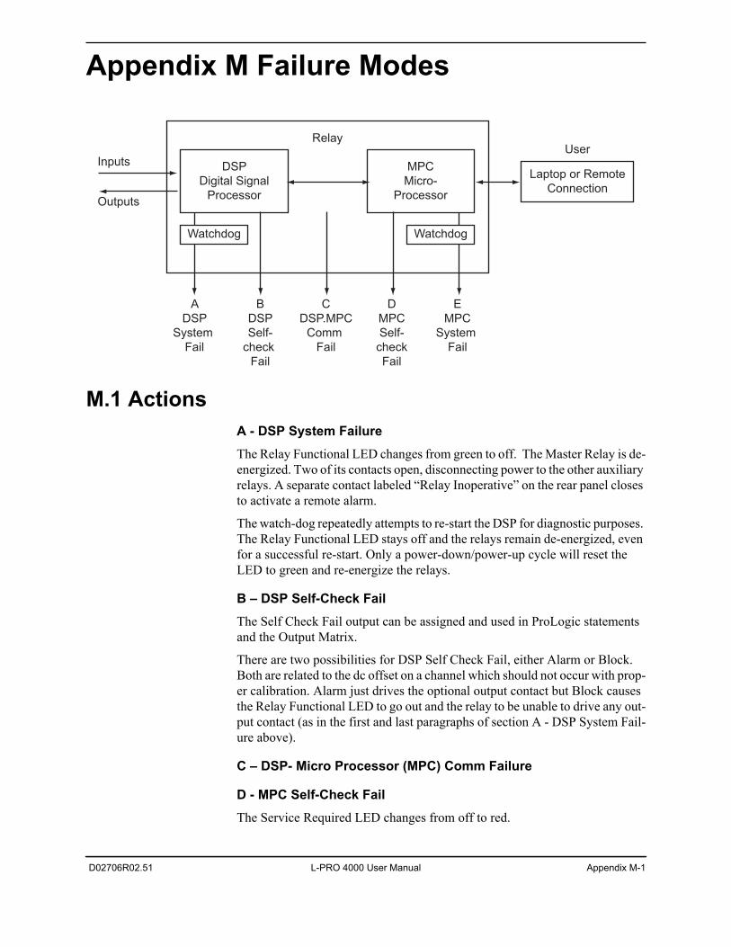
D02706R02.51 L-PRO 4000 User Manual Appendix M-1
Appendix M Failure Modes
M.1 ActionsA - DSP System FailureThe Relay Functional LED changes from green to off. The Master Relay is de-energized. Two of its contacts open, disconnecting power to the other auxiliary relays. A separate contact labeled “Relay Inoperative” on the rear panel closes to activate a remote alarm.
The watch-dog repeatedly attempts to re-start the DSP for diagnostic purposes. The Relay Functional LED stays off and the relays remain de-energized, even for a successful re-start. Only a power-down/power-up cycle will reset the LED to green and re-energize the relays.
B – DSP Self-Check FailThe Self Check Fail output can be assigned and used in ProLogic statements and the Output Matrix.
There are two possibilities for DSP Self Check Fail, either Alarm or Block. Both are related to the dc offset on a channel which should not occur with prop-er calibration. Alarm just drives the optional output contact but Block causes the Relay Functional LED to go out and the relay to be unable to drive any out-put contact (as in the first and last paragraphs of section A - DSP System Fail-ure above).
C – DSP- Micro Processor (MPC) Comm Failure
D - MPC Self-Check FailThe Service Required LED changes from off to red.
Outputs
InputsLaptop or Remote
Connection
User
A
DSP
System
Fail
B
DSP
Self-
check
Fail
C
DSP.MPC
Comm
Fail
D
MPC
Self-
check
Fail
E
MPC
System
Fail
DSP
Digital Signal
Processor
Watchdog
MPC
Micro-
Processor
Watchdog
Relay
Appendix M Failure Modes
Appendix M-2 L-PRO 4000 User Manual D02706R02.51
E – MPC System FailThe Test Mode LED changes from off to red until the MPC has rebooted. The watchdog will continue to attempt to re-start the MPC several times. If the MPC reboots but can not return to normal operation, the Service Required LED changes from off to red.
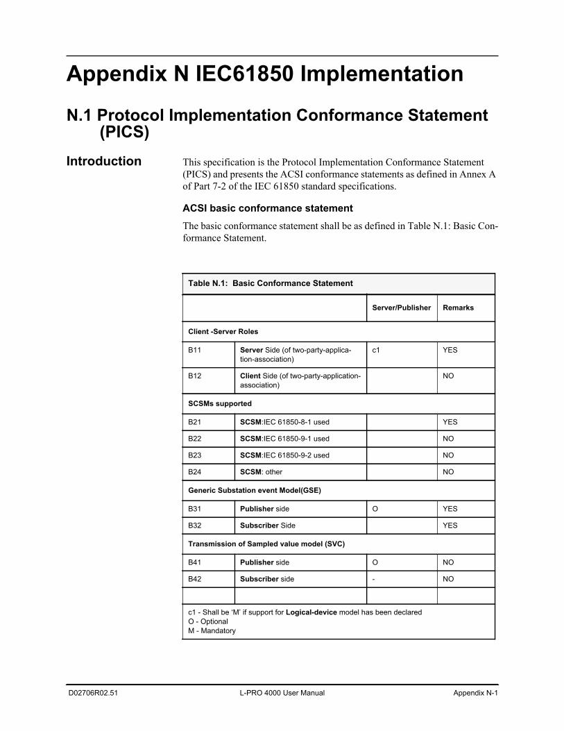
D02706R02.51 L-PRO 4000 User Manual Appendix N-1
Appendix N IEC61850 Implementation
N.1 Protocol Implementation Conformance Statement (PICS)
Introduction This specification is the Protocol Implementation Conformance Statement (PICS) and presents the ACSI conformance statements as defined in Annex A of Part 7-2 of the IEC 61850 standard specifications.
ACSI basic conformance statementThe basic conformance statement shall be as defined in Table N.1: Basic Con-formance Statement.
Table N.1: Basic Conformance Statement
Server/Publisher Remarks
Client -Server Roles
B11 Server Side (of two-party-applica-tion-association)
c1 YES
B12 Client Side (of two-party-application-association)
NO
SCSMs supported
B21 SCSM:IEC 61850-8-1 used YES
B22 SCSM:IEC 61850-9-1 used NO
B23 SCSM:IEC 61850-9-2 used NO
B24 SCSM: other NO
Generic Substation event Model(GSE)
B31 Publisher side O YES
B32 Subscriber Side YES
Transmission of Sampled value model (SVC)
B41 Publisher side O NO
B42 Subscriber side - NO
c1 - Shall be ‘M’ if support for Logical-device model has been declaredO - OptionalM - Mandatory
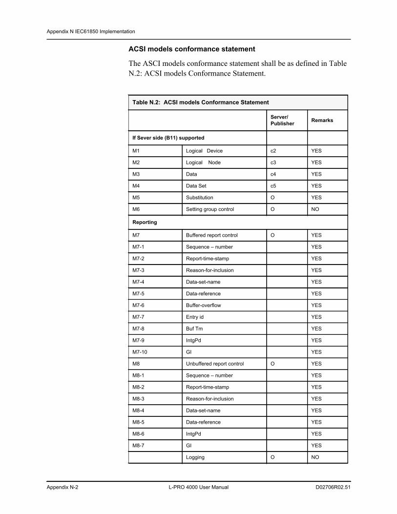
Appendix N IEC61850 Implementation
Appendix N-2 L-PRO 4000 User Manual D02706R02.51
ACSI models conformance statement
The ASCI models conformance statement shall be as defined in Table N.2: ACSI models Conformance Statement.
Table N.2: ACSI models Conformance Statement
Server/Publisher Remarks
If Sever side (B11) supported
M1 Logical Device c2 YES
M2 Logical Node c3 YES
M3 Data c4 YES
M4 Data Set c5 YES
M5 Substitution O YES
M6 Setting group control O NO
Reporting
M7 Buffered report control O YES
M7-1 Sequence – number YES
M7-2 Report-time-stamp YES
M7-3 Reason-for-inclusion YES
M7-4 Data-set-name YES
M7-5 Data-reference YES
M7-6 Buffer-overflow YES
M7-7 Entry id YES
M7-8 Buf Tm YES
M7-9 IntgPd YES
M7-10 GI YES
M8 Unbuffered report control O YES
M8-1 Sequence – number YES
M8-2 Report-time-stamp YES
M8-3 Reason-for-inclusion YES
M8-4 Data-set-name YES
M8-5 Data-reference YES
M8-6 IntgPd YES
M8-7 GI YES
Logging O NO
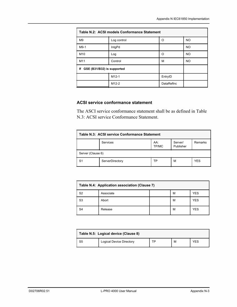
Appendix N IEC61850 Implementation
D02706R02.51 L-PRO 4000 User Manual Appendix N-3
ACSI service conformance statement
The ASCI service conformance statement shall be as defined in Table N.3: ACSI service Conformance Statement.
M9 Log control O NO
M9-1 IntgPd NO
M10 Log O NO
M11 Control M NO
If GSE (B31/B32) is supported
M12-1 EntryID
M12-2 DataReflnc
Table N.3: ACSI service Conformance Statement
Services AA:TP/MC
Server/Publisher
Remarks
Server (Clause 6)
S1 ServerDirectory TP M YES
Table N.4: Application association (Clause 7)
S2 Associate M YES
S3 Abort M YES
S4 Release M YES
Table N.5: Logical device (Clause 8)
S5 Logical Device Directory TP M YES
Table N.2: ACSI models Conformance Statement
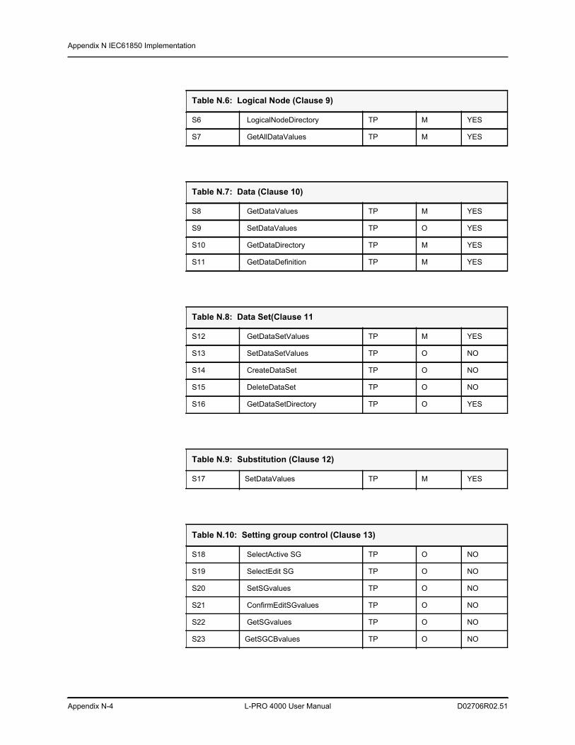
Appendix N IEC61850 Implementation
Appendix N-4 L-PRO 4000 User Manual D02706R02.51
Table N.6: Logical Node (Clause 9)
S6 LogicalNodeDirectory TP M YES
S7 GetAllDataValues TP M YES
Table N.7: Data (Clause 10)
S8 GetDataValues TP M YES
S9 SetDataValues TP O YES
S10 GetDataDirectory TP M YES
S11 GetDataDefinition TP M YES
Table N.8: Data Set(Clause 11
S12 GetDataSetValues TP M YES
S13 SetDataSetValues TP O NO
S14 CreateDataSet TP O NO
S15 DeleteDataSet TP O NO
S16 GetDataSetDirectory TP O YES
Table N.9: Substitution (Clause 12)
S17 SetDataValues TP M YES
Table N.10: Setting group control (Clause 13)
S18 SelectActive SG TP O NO
S19 SelectEdit SG TP O NO
S20 SetSGvalues TP O NO
S21 ConfirmEditSGvalues TP O NO
S22 GetSGvalues TP O NO
S23 GetSGCBvalues TP O NO
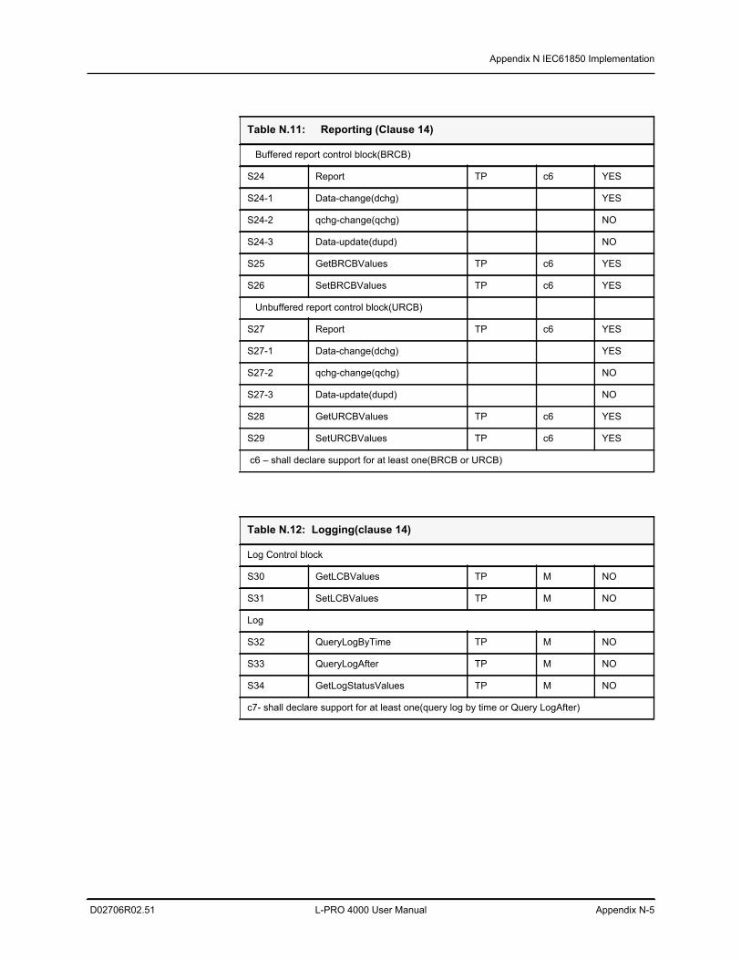
Appendix N IEC61850 Implementation
D02706R02.51 L-PRO 4000 User Manual Appendix N-5
Table N.11: Reporting (Clause 14)
Buffered report control block(BRCB)
S24 Report TP c6 YES
S24-1 Data-change(dchg) YES
S24-2 qchg-change(qchg) NO
S24-3 Data-update(dupd) NO
S25 GetBRCBValues TP c6 YES
S26 SetBRCBValues TP c6 YES
Unbuffered report control block(URCB)
S27 Report TP c6 YES
S27-1 Data-change(dchg) YES
S27-2 qchg-change(qchg) NO
S27-3 Data-update(dupd) NO
S28 GetURCBValues TP c6 YES
S29 SetURCBValues TP c6 YES
c6 – shall declare support for at least one(BRCB or URCB)
Table N.12: Logging(clause 14)
Log Control block
S30 GetLCBValues TP M NO
S31 SetLCBValues TP M NO
Log
S32 QueryLogByTime TP M NO
S33 QueryLogAfter TP M NO
S34 GetLogStatusValues TP M NO
c7- shall declare support for at least one(query log by time or Query LogAfter)
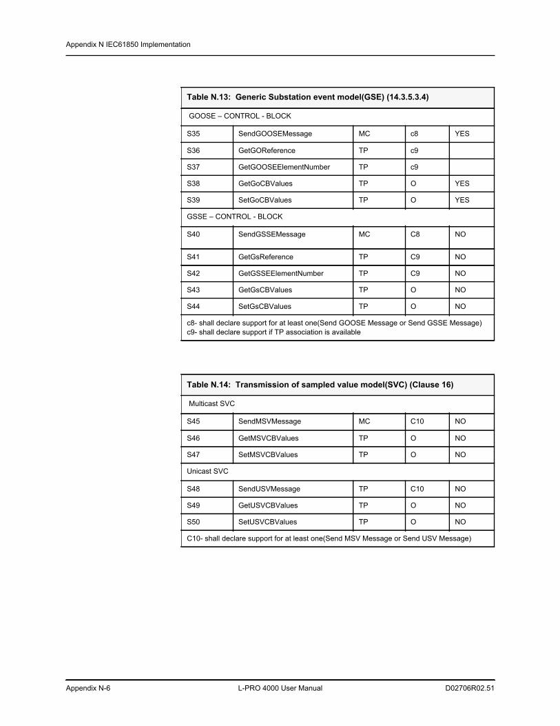
Appendix N IEC61850 Implementation
Appendix N-6 L-PRO 4000 User Manual D02706R02.51
Table N.13: Generic Substation event model(GSE) (14.3.5.3.4)
GOOSE – CONTROL - BLOCK
S35 SendGOOSEMessage MC c8 YES
S36 GetGOReference TP c9
S37 GetGOOSEElementNumber TP c9
S38 GetGoCBValues TP O YES
S39 SetGoCBValues TP O YES
GSSE – CONTROL - BLOCK
S40 SendGSSEMessage MC C8 NO
S41 GetGsReference TP C9 NO
S42 GetGSSEElementNumber TP C9 NO
S43 GetGsCBValues TP O NO
S44 SetGsCBValues TP O NO
c8- shall declare support for at least one(Send GOOSE Message or Send GSSE Message)c9- shall declare support if TP association is available
Table N.14: Transmission of sampled value model(SVC) (Clause 16)
Multicast SVC
S45 SendMSVMessage MC C10 NO
S46 GetMSVCBValues TP O NO
S47 SetMSVCBValues TP O NO
Unicast SVC
S48 SendUSVMessage TP C10 NO
S49 GetUSVCBValues TP O NO
S50 SetUSVCBValues TP O NO
C10- shall declare support for at least one(Send MSV Message or Send USV Message)
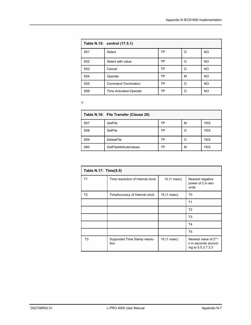
Appendix N IEC61850 Implementation
D02706R02.51 L-PRO 4000 User Manual Appendix N-7
v
Table N.15: control (17.5.1)
S51 Select TP O NO
S52 Select with value TP O NO
S53 Cancel TP O NO
S54 Operate TP M NO
S55 Command-Termination TP O NO
S56 Time Activated-Operate TP O NO
Table N.16: File Transfer (Clause 20)
S57 GetFile TP M YES
S58 SetFile TP O YES
S59 DeleteFile TP O YES
S60 GetFileAttributeValues TP M YES
Table N.17: Time(5.5)
T1 Time resolution of Internal clock 10 (1 msec) Nearest negative power of 2 in sec-onds
T2 TimeAccuracy of Internal clock 10 (1 msec) T0
T1
T2
T3
T4
T5
T3 Supported Time Stamp resolu-tion
10 (1 msec) Nearest value of 2**-n in seconds accord-ing to 5.5.3.7.3.3
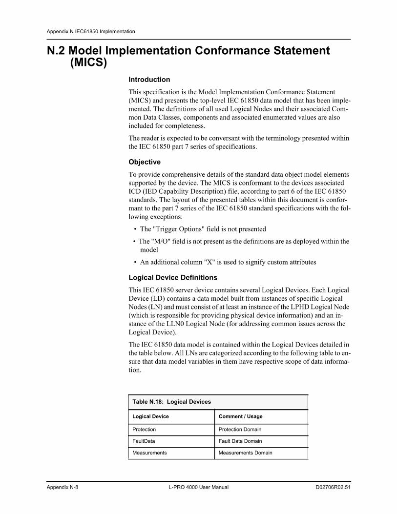
Appendix N IEC61850 Implementation
Appendix N-8 L-PRO 4000 User Manual D02706R02.51
N.2 Model Implementation Conformance Statement (MICS)
IntroductionThis specification is the Model Implementation Conformance Statement (MICS) and presents the top-level IEC 61850 data model that has been imple-mented. The definitions of all used Logical Nodes and their associated Com-mon Data Classes, components and associated enumerated values are also included for completeness.
The reader is expected to be conversant with the terminology presented within the IEC 61850 part 7 series of specifications.
ObjectiveTo provide comprehensive details of the standard data object model elements supported by the device. The MICS is conformant to the devices associated ICD (IED Capability Description) file, according to part 6 of the IEC 61850 standards. The layout of the presented tables within this document is confor-mant to the part 7 series of the IEC 61850 standard specifications with the fol-lowing exceptions:
• The "Trigger Options" field is not presented
• The "M/O" field is not present as the definitions are as deployed within the model
• An additional column "X" is used to signify custom attributes
Logical Device DefinitionsThis IEC 61850 server device contains several Logical Devices. Each Logical Device (LD) contains a data model built from instances of specific Logical Nodes (LN) and must consist of at least an instance of the LPHD Logical Node (which is responsible for providing physical device information) and an in-stance of the LLN0 Logical Node (for addressing common issues across the Logical Device).
The IEC 61850 data model is contained within the Logical Devices detailed in the table below. All LNs are categorized according to the following table to en-sure that data model variables in them have respective scope of data informa-tion.
Table N.18: Logical Devices
Logical Device Comment / Usage
Protection Protection Domain
FaultData Fault Data Domain
Measurements Measurements Domain
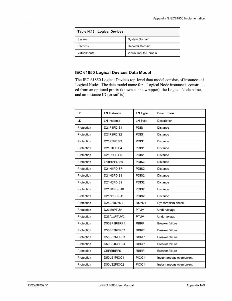
Appendix N IEC61850 Implementation
D02706R02.51 L-PRO 4000 User Manual Appendix N-9
IEC 61850 Logical Devices Data ModelThe IEC 61850 Logical Devices top-level data model consists of instances of Logical Nodes. The data model name for a Logical Node instance is construct-ed from an optional prefix (known as the wrapper), the Logical Node name, and an instance ID (or suffix).
System System Domain
Records Records Domain
VirtualInputs Virtual Inputs Domain
LD LN Instance LN Type Description
LD LN Instance LN Type Description
Protection D21P1PDIS1 PDIS1 Distance
Protection D21P2PDIS2 PDIS1 Distance
Protection D21P3PDIS3 PDIS1 Distance
Protection D21P4PDIS4 PDIS1 Distance
Protection D21P5PDIS5 PDIS1 Distance
Protection LodEncPDIS6 PDIS3 Distance
Protection D21N1PDIS7 PDIS2 Distance
Protection D21N2PDIS8 PDIS2 Distance
Protection D21N3PDIS9 PDIS2 Distance
Protection D21N4PDIS10 PDIS2 Distance
Protection D21N5PDIS11 PDIS2 Distance
Protection D2527RSYN1 RSYN1 Synchronism-check
Protection D27MnPTUV1 PTUV1 Undervoltage
Protection D27AuxPTUV2 PTUV1 Undervoltage
Protection D50BF1RBRF1 RBRF1 Breaker failure
Protection D50BF2RBRF2 RBRF1 Breaker failure
Protection D50BF3RBRF3 RBRF1 Breaker failure
Protection D50BF4RBRF4 RBRF1 Breaker failure
Protection CBFIRBRF5 RBRF1 Breaker failure
Protection D50LS1PIOC1 PIOC1 Instantaneous overcurrent
Protection D50LS2PIOC2 PIOC1 Instantaneous overcurrent
Table N.18: Logical Devices
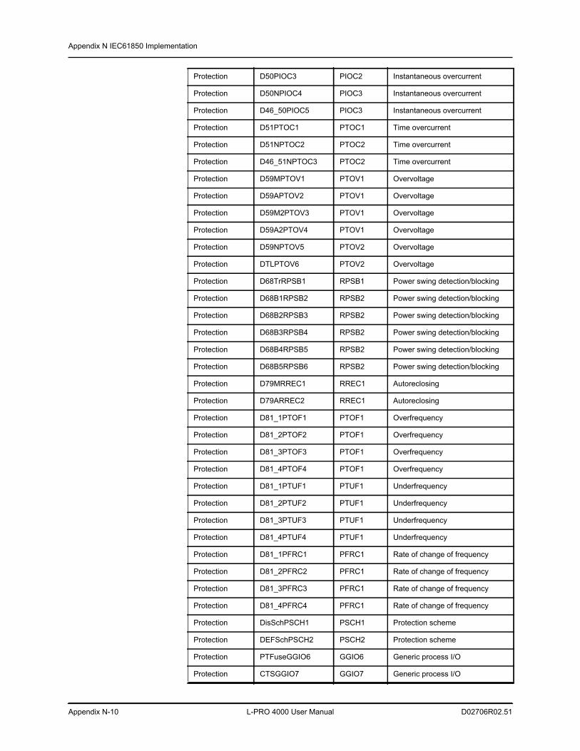
Appendix N IEC61850 Implementation
Appendix N-10 L-PRO 4000 User Manual D02706R02.51
Protection D50PIOC3 PIOC2 Instantaneous overcurrent
Protection D50NPIOC4 PIOC3 Instantaneous overcurrent
Protection D46_50PIOC5 PIOC3 Instantaneous overcurrent
Protection D51PTOC1 PTOC1 Time overcurrent
Protection D51NPTOC2 PTOC2 Time overcurrent
Protection D46_51NPTOC3 PTOC2 Time overcurrent
Protection D59MPTOV1 PTOV1 Overvoltage
Protection D59APTOV2 PTOV1 Overvoltage
Protection D59M2PTOV3 PTOV1 Overvoltage
Protection D59A2PTOV4 PTOV1 Overvoltage
Protection D59NPTOV5 PTOV2 Overvoltage
Protection DTLPTOV6 PTOV2 Overvoltage
Protection D68TrRPSB1 RPSB1 Power swing detection/blocking
Protection D68B1RPSB2 RPSB2 Power swing detection/blocking
Protection D68B2RPSB3 RPSB2 Power swing detection/blocking
Protection D68B3RPSB4 RPSB2 Power swing detection/blocking
Protection D68B4RPSB5 RPSB2 Power swing detection/blocking
Protection D68B5RPSB6 RPSB2 Power swing detection/blocking
Protection D79MRREC1 RREC1 Autoreclosing
Protection D79ARREC2 RREC1 Autoreclosing
Protection D81_1PTOF1 PTOF1 Overfrequency
Protection D81_2PTOF2 PTOF1 Overfrequency
Protection D81_3PTOF3 PTOF1 Overfrequency
Protection D81_4PTOF4 PTOF1 Overfrequency
Protection D81_1PTUF1 PTUF1 Underfrequency
Protection D81_2PTUF2 PTUF1 Underfrequency
Protection D81_3PTUF3 PTUF1 Underfrequency
Protection D81_4PTUF4 PTUF1 Underfrequency
Protection D81_1PFRC1 PFRC1 Rate of change of frequency
Protection D81_2PFRC2 PFRC1 Rate of change of frequency
Protection D81_3PFRC3 PFRC1 Rate of change of frequency
Protection D81_4PFRC4 PFRC1 Rate of change of frequency
Protection DisSchPSCH1 PSCH1 Protection scheme
Protection DEFSchPSCH2 PSCH2 Protection scheme
Protection PTFuseGGIO6 GGIO6 Generic process I/O
Protection CTSGGIO7 GGIO7 Generic process I/O
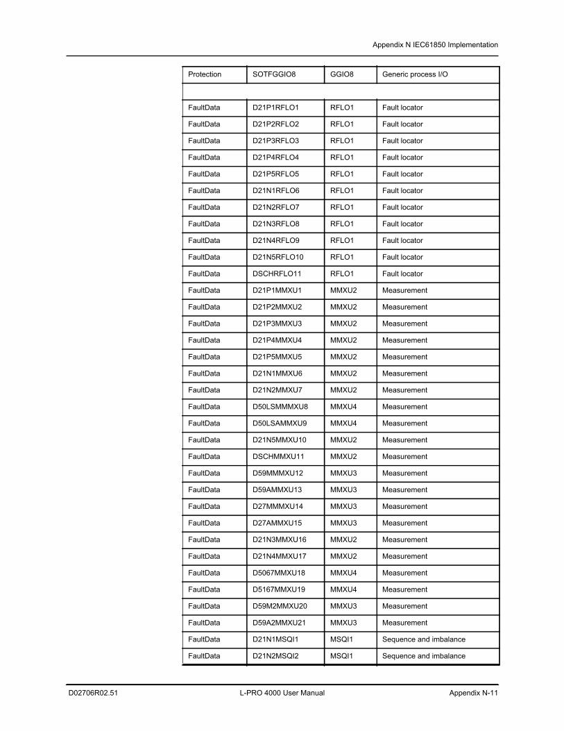
Appendix N IEC61850 Implementation
D02706R02.51 L-PRO 4000 User Manual Appendix N-11
Protection SOTFGGIO8 GGIO8 Generic process I/O
FaultData D21P1RFLO1 RFLO1 Fault locator
FaultData D21P2RFLO2 RFLO1 Fault locator
FaultData D21P3RFLO3 RFLO1 Fault locator
FaultData D21P4RFLO4 RFLO1 Fault locator
FaultData D21P5RFLO5 RFLO1 Fault locator
FaultData D21N1RFLO6 RFLO1 Fault locator
FaultData D21N2RFLO7 RFLO1 Fault locator
FaultData D21N3RFLO8 RFLO1 Fault locator
FaultData D21N4RFLO9 RFLO1 Fault locator
FaultData D21N5RFLO10 RFLO1 Fault locator
FaultData DSCHRFLO11 RFLO1 Fault locator
FaultData D21P1MMXU1 MMXU2 Measurement
FaultData D21P2MMXU2 MMXU2 Measurement
FaultData D21P3MMXU3 MMXU2 Measurement
FaultData D21P4MMXU4 MMXU2 Measurement
FaultData D21P5MMXU5 MMXU2 Measurement
FaultData D21N1MMXU6 MMXU2 Measurement
FaultData D21N2MMXU7 MMXU2 Measurement
FaultData D50LSMMMXU8 MMXU4 Measurement
FaultData D50LSAMMXU9 MMXU4 Measurement
FaultData D21N5MMXU10 MMXU2 Measurement
FaultData DSCHMMXU11 MMXU2 Measurement
FaultData D59MMMXU12 MMXU3 Measurement
FaultData D59AMMXU13 MMXU3 Measurement
FaultData D27MMMXU14 MMXU3 Measurement
FaultData D27AMMXU15 MMXU3 Measurement
FaultData D21N3MMXU16 MMXU2 Measurement
FaultData D21N4MMXU17 MMXU2 Measurement
FaultData D5067MMXU18 MMXU4 Measurement
FaultData D5167MMXU19 MMXU4 Measurement
FaultData D59M2MMXU20 MMXU3 Measurement
FaultData D59A2MMXU21 MMXU3 Measurement
FaultData D21N1MSQI1 MSQI1 Sequence and imbalance
FaultData D21N2MSQI2 MSQI1 Sequence and imbalance
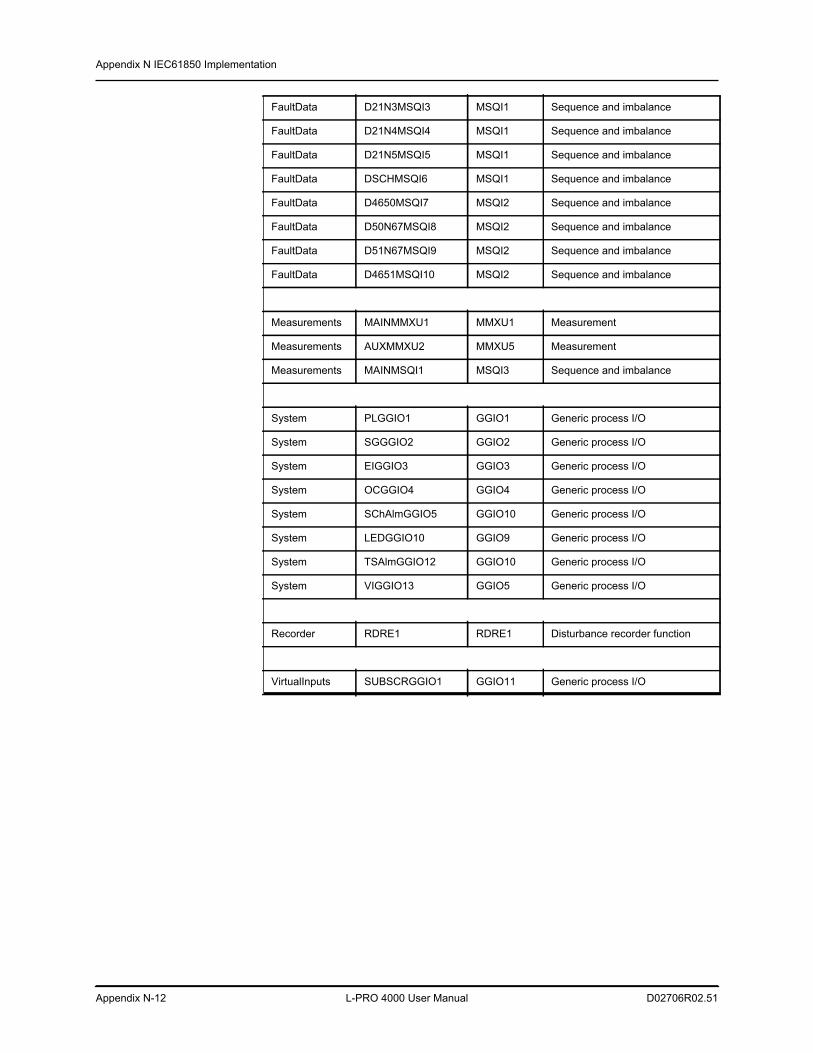
Appendix N IEC61850 Implementation
Appendix N-12 L-PRO 4000 User Manual D02706R02.51
FaultData D21N3MSQI3 MSQI1 Sequence and imbalance
FaultData D21N4MSQI4 MSQI1 Sequence and imbalance
FaultData D21N5MSQI5 MSQI1 Sequence and imbalance
FaultData DSCHMSQI6 MSQI1 Sequence and imbalance
FaultData D4650MSQI7 MSQI2 Sequence and imbalance
FaultData D50N67MSQI8 MSQI2 Sequence and imbalance
FaultData D51N67MSQI9 MSQI2 Sequence and imbalance
FaultData D4651MSQI10 MSQI2 Sequence and imbalance
Measurements MAINMMXU1 MMXU1 Measurement
Measurements AUXMMXU2 MMXU5 Measurement
Measurements MAINMSQI1 MSQI3 Sequence and imbalance
System PLGGIO1 GGIO1 Generic process I/O
System SGGGIO2 GGIO2 Generic process I/O
System EIGGIO3 GGIO3 Generic process I/O
System OCGGIO4 GGIO4 Generic process I/O
System SChAlmGGIO5 GGIO10 Generic process I/O
System LEDGGIO10 GGIO9 Generic process I/O
System TSAlmGGIO12 GGIO10 Generic process I/O
System VIGGIO13 GGIO5 Generic process I/O
Recorder RDRE1 RDRE1 Disturbance recorder function
VirtualInputs SUBSCRGGIO1 GGIO11 Generic process I/O
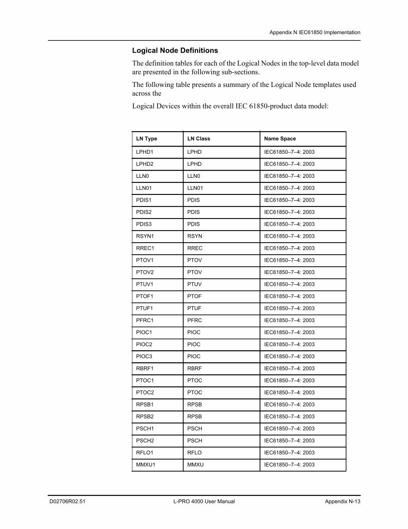
Appendix N IEC61850 Implementation
D02706R02.51 L-PRO 4000 User Manual Appendix N-13
Logical Node DefinitionsThe definition tables for each of the Logical Nodes in the top-level data model are presented in the following sub-sections.
The following table presents a summary of the Logical Node templates used across the
Logical Devices within the overall IEC 61850-product data model:
LN Type LN Class Name Space
LPHD1 LPHD IEC61850–7–4: 2003
LPHD2 LPHD IEC61850–7–4: 2003
LLN0 LLN0 IEC61850–7–4: 2003
LLN01 LLN01 IEC61850–7–4: 2003
PDIS1 PDIS IEC61850–7–4: 2003
PDIS2 PDIS IEC61850–7–4: 2003
PDIS3 PDIS IEC61850–7–4: 2003
RSYN1 RSYN IEC61850–7–4: 2003
RREC1 RREC IEC61850–7–4: 2003
PTOV1 PTOV IEC61850–7–4: 2003
PTOV2 PTOV IEC61850–7–4: 2003
PTUV1 PTUV IEC61850–7–4: 2003
PTOF1 PTOF IEC61850–7–4: 2003
PTUF1 PTUF IEC61850–7–4: 2003
PFRC1 PFRC IEC61850–7–4: 2003
PIOC1 PIOC IEC61850–7–4: 2003
PIOC2 PIOC IEC61850–7–4: 2003
PIOC3 PIOC IEC61850–7–4: 2003
RBRF1 RBRF IEC61850–7–4: 2003
PTOC1 PTOC IEC61850–7–4: 2003
PTOC2 PTOC IEC61850–7–4: 2003
RPSB1 RPSB IEC61850–7–4: 2003
RPSB2 RPSB IEC61850–7–4: 2003
PSCH1 PSCH IEC61850–7–4: 2003
PSCH2 PSCH IEC61850–7–4: 2003
RFLO1 RFLO IEC61850–7–4: 2003
MMXU1 MMXU IEC61850–7–4: 2003

Appendix N IEC61850 Implementation
Appendix N-14 L-PRO 4000 User Manual D02706R02.51
Logical Node: LPHD1Description: Physical Device Information
LN Class: LPHD
MMXU2 MMXU IEC61850–7–4: 2003
MMXU3 MMXU IEC61850–7–4: 2003
MMXU4 MMXU IEC61850–7–4: 2003
MMXU5 MMXU IEC61850–7–4: 2003
MSQI1 MSQI IEC61850–7–4: 2003
MSQI2 MSQI IEC61850–7–4: 2003
MSQI3 MSQI IEC61850–7–4: 2003
GGIO1 GGIO IEC61850–7–4: 2003
GGIO2 GGIO IEC61850–7–4: 2003
GGIO3 GGIO IEC61850–7–4: 2003
GGIO4 GGIO IEC61850–7–4: 2003
GGIO5 GGIO IEC61850–7–4: 2003
GGIO6 GGIO IEC61850–7–4: 2003
GGIO7 GGIO IEC61850–7–4: 2003
GGIO8 GGIO IEC61850–7–4: 2003
GGIO9 GGIO IEC61850–7–4: 2003
GGIO10 GGIO IEC61850–7–4: 2003
GGIO11 GGIO IEC61850–7–4: 2003
RDRE1 RDRE IEC61850–7–4: 2003
Attribute Attr. Type Explanation T X
PhyNam DPL_2_PhyNam Device Physical Name Plate
PhyHealth INS_2_PhyHealth Physical Device Health
Proxy SPS_1_Proxy Indicates if this device is proxy
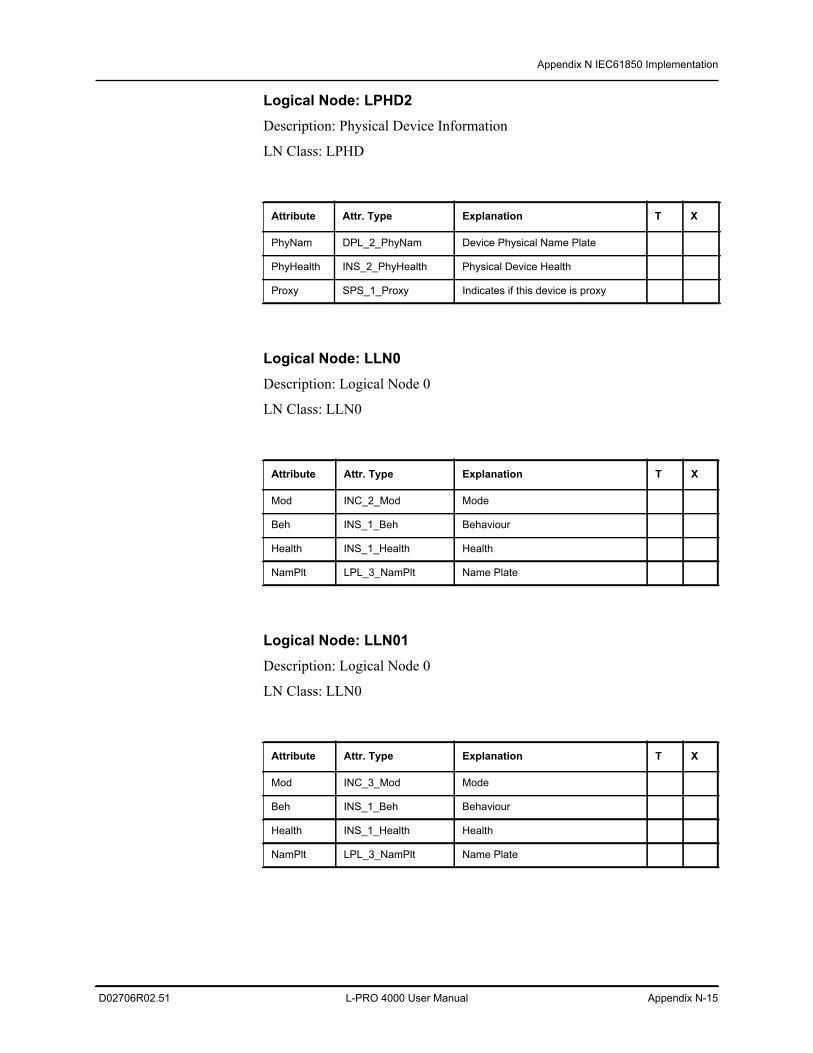
Appendix N IEC61850 Implementation
D02706R02.51 L-PRO 4000 User Manual Appendix N-15
Logical Node: LPHD2Description: Physical Device Information
LN Class: LPHD
Logical Node: LLN0Description: Logical Node 0
LN Class: LLN0
Logical Node: LLN01Description: Logical Node 0
LN Class: LLN0
Attribute Attr. Type Explanation T X
PhyNam DPL_2_PhyNam Device Physical Name Plate
PhyHealth INS_2_PhyHealth Physical Device Health
Proxy SPS_1_Proxy Indicates if this device is proxy
Attribute Attr. Type Explanation T X
Mod INC_2_Mod Mode
Beh INS_1_Beh Behaviour
Health INS_1_Health Health
NamPlt LPL_3_NamPlt Name Plate
Attribute Attr. Type Explanation T X
Mod INC_3_Mod Mode
Beh INS_1_Beh Behaviour
Health INS_1_Health Health
NamPlt LPL_3_NamPlt Name Plate
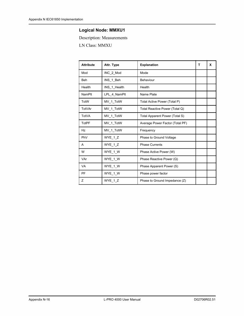
Appendix N IEC61850 Implementation
Appendix N-16 L-PRO 4000 User Manual D02706R02.51
Logical Node: MMXU1Description: Measurements
LN Class: MMXU
Attribute Attr. Type Explanation T X
Mod INC_2_Mod Mode
Beh INS_1_Beh Behaviour
Health INS_1_Health Health
NamPlt LPL_4_NamPlt Name Plate
TotW MV_1_TotW Total Active Power (Total P)
TotVAr MV_1_TotW Total Reactive Power (Total Q)
TotVA MV_1_TotW Total Apparent Power (Total S)
TotPF MV_1_TotW Average Power Factor (Total PF)
Hz MV_1_TotW Frequency
PhV WYE_1_Z Phase to Ground Voltage
A WYE_1_Z Phase Currents
W WYE_1_W Phase Active Power (W)
VAr WYE_1_W Phase Reactive Power (Q)
VA WYE_1_W Phase Apparent Power (S)
PF WYE_1_W Phase power factor
Z WYE_1_Z Phase to Ground Impedance (Z)
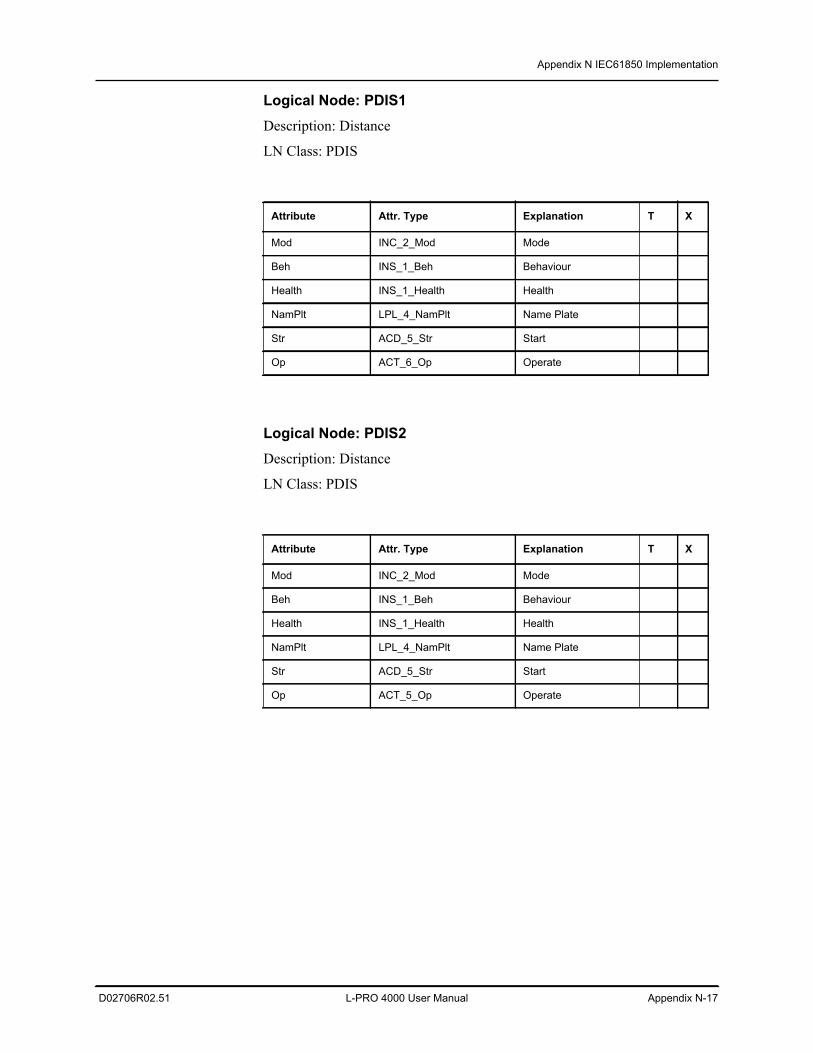
Appendix N IEC61850 Implementation
D02706R02.51 L-PRO 4000 User Manual Appendix N-17
Logical Node: PDIS1Description: Distance
LN Class: PDIS
Logical Node: PDIS2Description: Distance
LN Class: PDIS
Attribute Attr. Type Explanation T X
Mod INC_2_Mod Mode
Beh INS_1_Beh Behaviour
Health INS_1_Health Health
NamPlt LPL_4_NamPlt Name Plate
Str ACD_5_Str Start
Op ACT_6_Op Operate
Attribute Attr. Type Explanation T X
Mod INC_2_Mod Mode
Beh INS_1_Beh Behaviour
Health INS_1_Health Health
NamPlt LPL_4_NamPlt Name Plate
Str ACD_5_Str Start
Op ACT_5_Op Operate
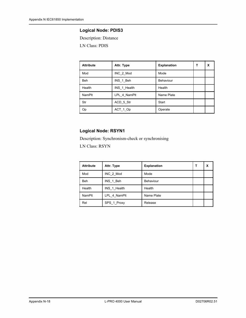
Appendix N IEC61850 Implementation
Appendix N-18 L-PRO 4000 User Manual D02706R02.51
Logical Node: PDIS3Description: Distance
LN Class: PDIS
Logical Node: RSYN1Description: Synchronism-check or synchronising
LN Class: RSYN
Attribute Attr. Type Explanation T X
Mod INC_2_Mod Mode
Beh INS_1_Beh Behaviour
Health INS_1_Health Health
NamPlt LPL_4_NamPlt Name Plate
Str ACD_5_Str Start
Op ACT_1_Op Operate
Attribute Attr. Type Explanation T X
Mod INC_2_Mod Mode
Beh INS_1_Beh Behaviour
Health INS_1_Health Health
NamPlt LPL_4_NamPlt Name Plate
Rel SPS_1_Proxy Release
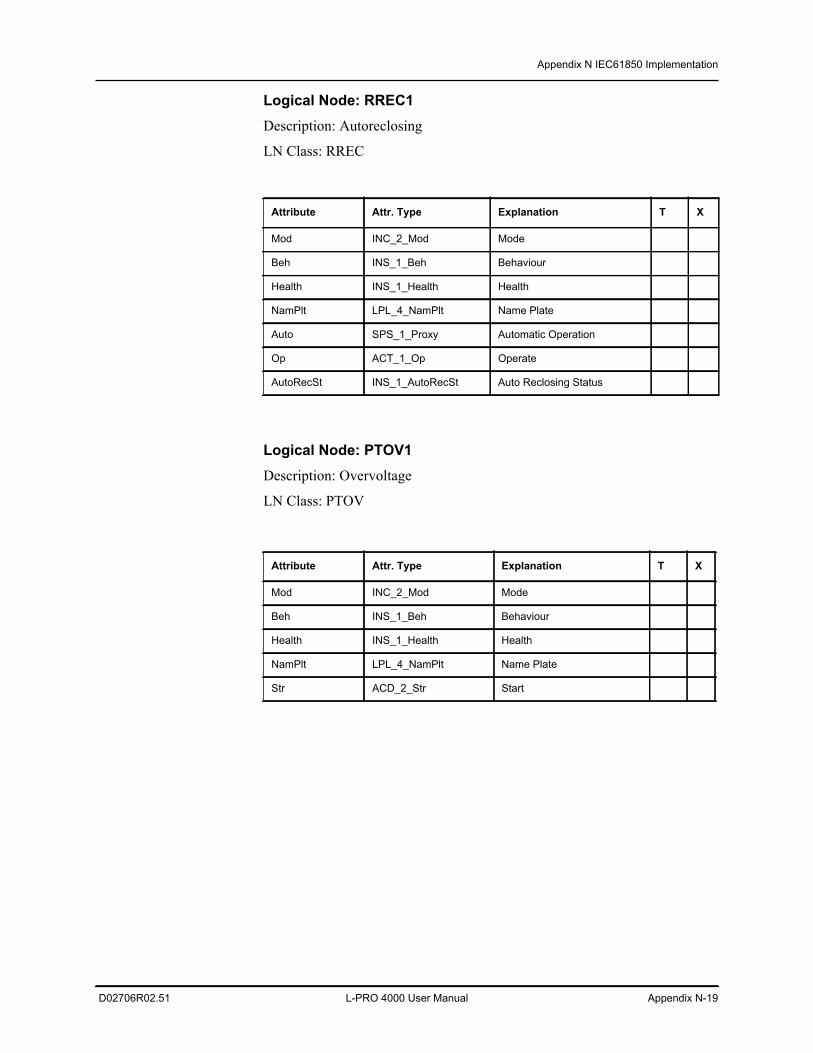
Appendix N IEC61850 Implementation
D02706R02.51 L-PRO 4000 User Manual Appendix N-19
Logical Node: RREC1Description: Autoreclosing
LN Class: RREC
Logical Node: PTOV1Description: Overvoltage
LN Class: PTOV
Attribute Attr. Type Explanation T X
Mod INC_2_Mod Mode
Beh INS_1_Beh Behaviour
Health INS_1_Health Health
NamPlt LPL_4_NamPlt Name Plate
Auto SPS_1_Proxy Automatic Operation
Op ACT_1_Op Operate
AutoRecSt INS_1_AutoRecSt Auto Reclosing Status
Attribute Attr. Type Explanation T X
Mod INC_2_Mod Mode
Beh INS_1_Beh Behaviour
Health INS_1_Health Health
NamPlt LPL_4_NamPlt Name Plate
Str ACD_2_Str Start
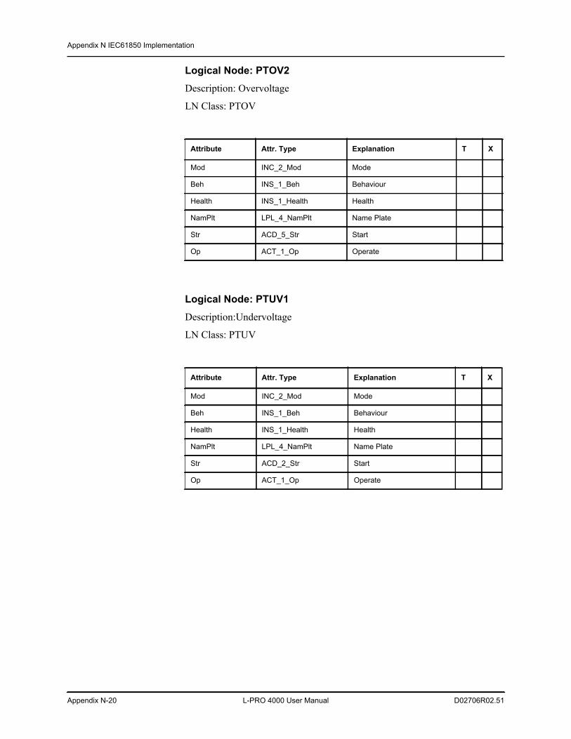
Appendix N IEC61850 Implementation
Appendix N-20 L-PRO 4000 User Manual D02706R02.51
Logical Node: PTOV2Description: Overvoltage
LN Class: PTOV
Logical Node: PTUV1Description:Undervoltage
LN Class: PTUV
Attribute Attr. Type Explanation T X
Mod INC_2_Mod Mode
Beh INS_1_Beh Behaviour
Health INS_1_Health Health
NamPlt LPL_4_NamPlt Name Plate
Str ACD_5_Str Start
Op ACT_1_Op Operate
Attribute Attr. Type Explanation T X
Mod INC_2_Mod Mode
Beh INS_1_Beh Behaviour
Health INS_1_Health Health
NamPlt LPL_4_NamPlt Name Plate
Str ACD_2_Str Start
Op ACT_1_Op Operate
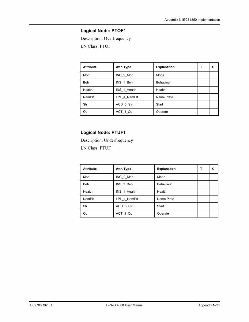
Appendix N IEC61850 Implementation
D02706R02.51 L-PRO 4000 User Manual Appendix N-21
Logical Node: PTOF1Description: Overfrequency
LN Class: PTOF
Logical Node: PTUF1Description: Underfrequency
LN Class: PTUF
Attribute Attr. Type Explanation T X
Mod INC_2_Mod Mode
Beh INS_1_Beh Behaviour
Health INS_1_Health Health
NamPlt LPL_4_NamPlt Name Plate
Str ACD_5_Str Start
Op ACT_1_Op Operate
Attribute Attr. Type Explanation T X
Mod INC_2_Mod Mode
Beh INS_1_Beh Behaviour
Health INS_1_Health Health
NamPlt LPL_4_NamPlt Name Plate
Str ACD_5_Str Start
Op ACT_1_Op Operate
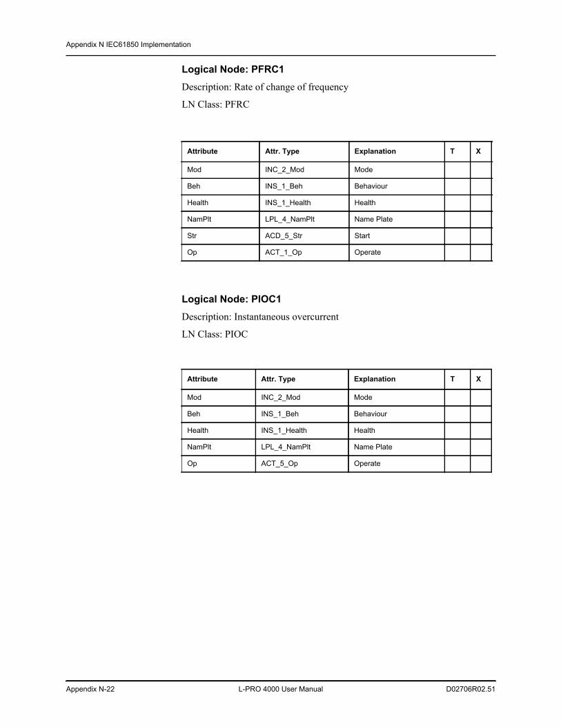
Appendix N IEC61850 Implementation
Appendix N-22 L-PRO 4000 User Manual D02706R02.51
Logical Node: PFRC1Description: Rate of change of frequency
LN Class: PFRC
Logical Node: PIOC1Description: Instantaneous overcurrent
LN Class: PIOC
Attribute Attr. Type Explanation T X
Mod INC_2_Mod Mode
Beh INS_1_Beh Behaviour
Health INS_1_Health Health
NamPlt LPL_4_NamPlt Name Plate
Str ACD_5_Str Start
Op ACT_1_Op Operate
Attribute Attr. Type Explanation T X
Mod INC_2_Mod Mode
Beh INS_1_Beh Behaviour
Health INS_1_Health Health
NamPlt LPL_4_NamPlt Name Plate
Op ACT_5_Op Operate
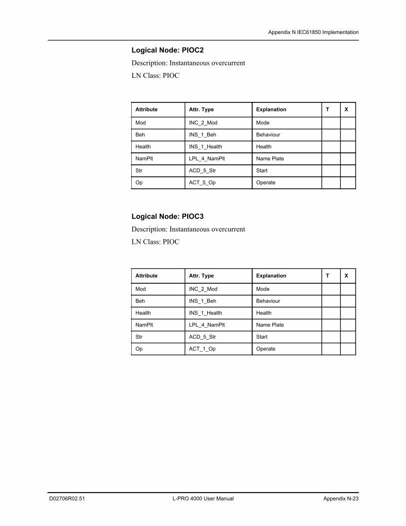
Appendix N IEC61850 Implementation
D02706R02.51 L-PRO 4000 User Manual Appendix N-23
Logical Node: PIOC2Description: Instantaneous overcurrent
LN Class: PIOC
Logical Node: PIOC3Description: Instantaneous overcurrent
LN Class: PIOC
Attribute Attr. Type Explanation T X
Mod INC_2_Mod Mode
Beh INS_1_Beh Behaviour
Health INS_1_Health Health
NamPlt LPL_4_NamPlt Name Plate
Str ACD_5_Str Start
Op ACT_5_Op Operate
Attribute Attr. Type Explanation T X
Mod INC_2_Mod Mode
Beh INS_1_Beh Behaviour
Health INS_1_Health Health
NamPlt LPL_4_NamPlt Name Plate
Str ACD_5_Str Start
Op ACT_1_Op Operate
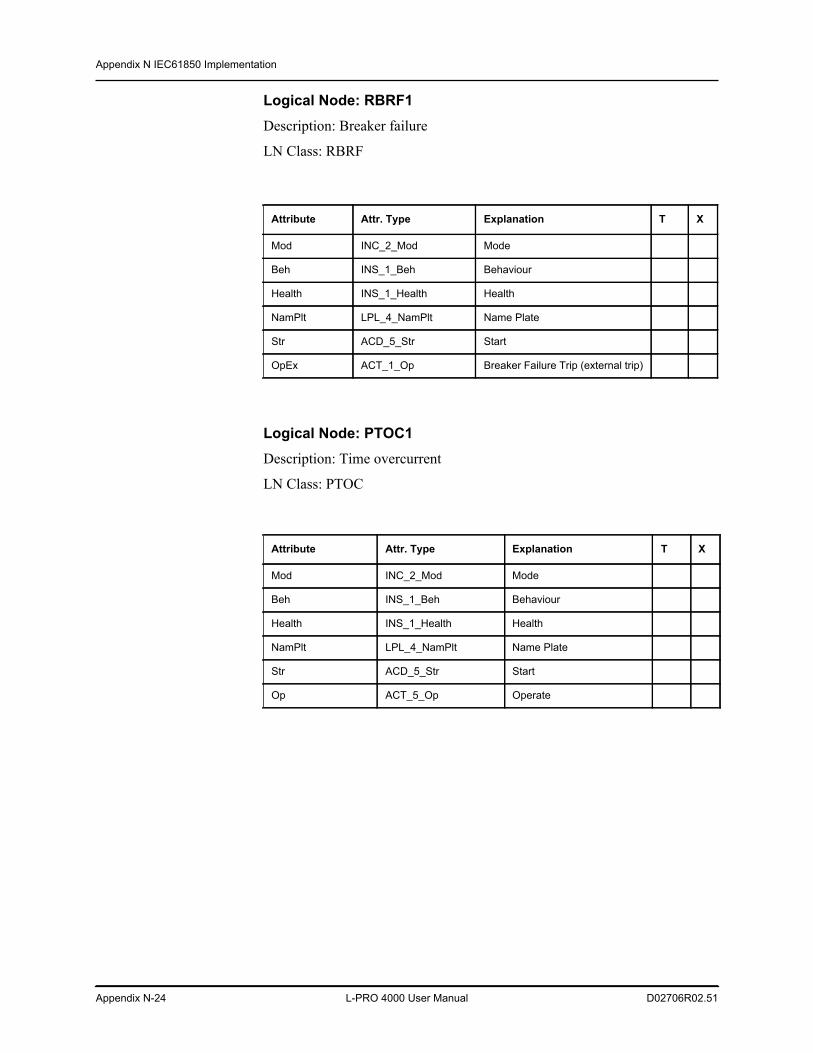
Appendix N IEC61850 Implementation
Appendix N-24 L-PRO 4000 User Manual D02706R02.51
Logical Node: RBRF1Description: Breaker failure
LN Class: RBRF
Logical Node: PTOC1Description: Time overcurrent
LN Class: PTOC
Attribute Attr. Type Explanation T X
Mod INC_2_Mod Mode
Beh INS_1_Beh Behaviour
Health INS_1_Health Health
NamPlt LPL_4_NamPlt Name Plate
Str ACD_5_Str Start
OpEx ACT_1_Op Breaker Failure Trip (external trip)
Attribute Attr. Type Explanation T X
Mod INC_2_Mod Mode
Beh INS_1_Beh Behaviour
Health INS_1_Health Health
NamPlt LPL_4_NamPlt Name Plate
Str ACD_5_Str Start
Op ACT_5_Op Operate
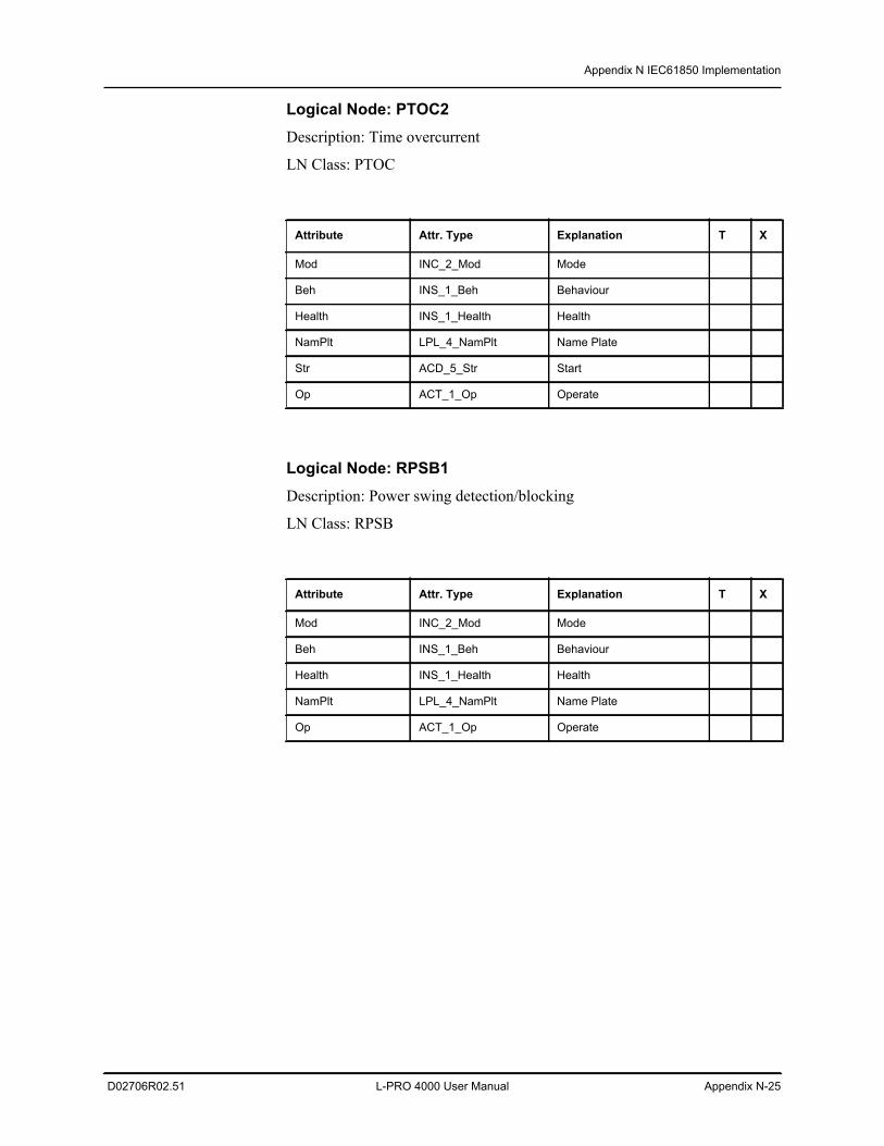
Appendix N IEC61850 Implementation
D02706R02.51 L-PRO 4000 User Manual Appendix N-25
Logical Node: PTOC2Description: Time overcurrent
LN Class: PTOC
Logical Node: RPSB1Description: Power swing detection/blocking
LN Class: RPSB
Attribute Attr. Type Explanation T X
Mod INC_2_Mod Mode
Beh INS_1_Beh Behaviour
Health INS_1_Health Health
NamPlt LPL_4_NamPlt Name Plate
Str ACD_5_Str Start
Op ACT_1_Op Operate
Attribute Attr. Type Explanation T X
Mod INC_2_Mod Mode
Beh INS_1_Beh Behaviour
Health INS_1_Health Health
NamPlt LPL_4_NamPlt Name Plate
Op ACT_1_Op Operate
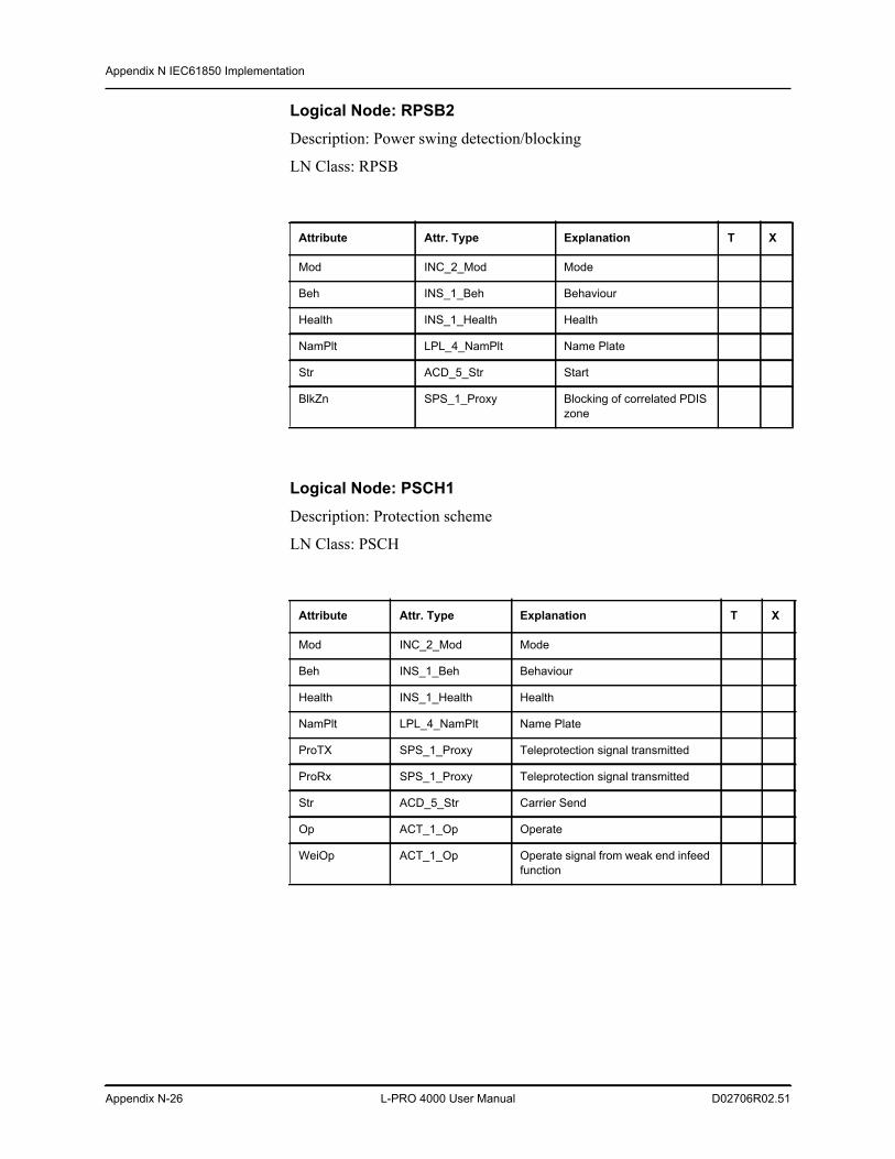
Appendix N IEC61850 Implementation
Appendix N-26 L-PRO 4000 User Manual D02706R02.51
Logical Node: RPSB2Description: Power swing detection/blocking
LN Class: RPSB
Logical Node: PSCH1Description: Protection scheme
LN Class: PSCH
Attribute Attr. Type Explanation T X
Mod INC_2_Mod Mode
Beh INS_1_Beh Behaviour
Health INS_1_Health Health
NamPlt LPL_4_NamPlt Name Plate
Str ACD_5_Str Start
BlkZn SPS_1_Proxy Blocking of correlated PDIS zone
Attribute Attr. Type Explanation T X
Mod INC_2_Mod Mode
Beh INS_1_Beh Behaviour
Health INS_1_Health Health
NamPlt LPL_4_NamPlt Name Plate
ProTX SPS_1_Proxy Teleprotection signal transmitted
ProRx SPS_1_Proxy Teleprotection signal transmitted
Str ACD_5_Str Carrier Send
Op ACT_1_Op Operate
WeiOp ACT_1_Op Operate signal from weak end infeed function
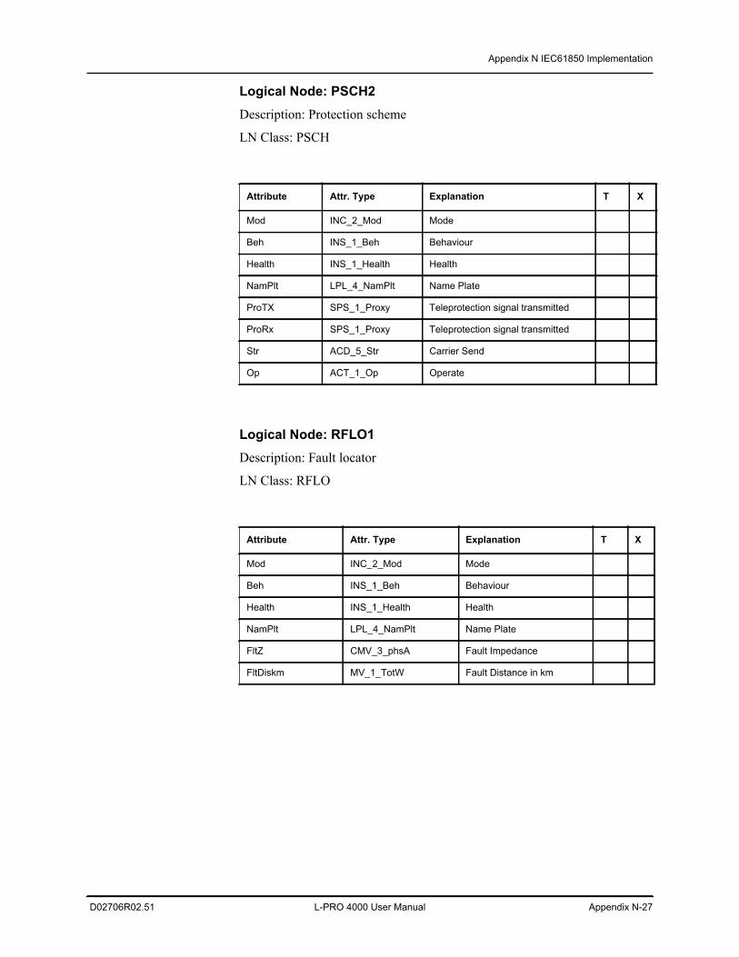
Appendix N IEC61850 Implementation
D02706R02.51 L-PRO 4000 User Manual Appendix N-27
Logical Node: PSCH2Description: Protection scheme
LN Class: PSCH
Logical Node: RFLO1Description: Fault locator
LN Class: RFLO
Attribute Attr. Type Explanation T X
Mod INC_2_Mod Mode
Beh INS_1_Beh Behaviour
Health INS_1_Health Health
NamPlt LPL_4_NamPlt Name Plate
ProTX SPS_1_Proxy Teleprotection signal transmitted
ProRx SPS_1_Proxy Teleprotection signal transmitted
Str ACD_5_Str Carrier Send
Op ACT_1_Op Operate
Attribute Attr. Type Explanation T X
Mod INC_2_Mod Mode
Beh INS_1_Beh Behaviour
Health INS_1_Health Health
NamPlt LPL_4_NamPlt Name Plate
FltZ CMV_3_phsA Fault Impedance
FltDiskm MV_1_TotW Fault Distance in km
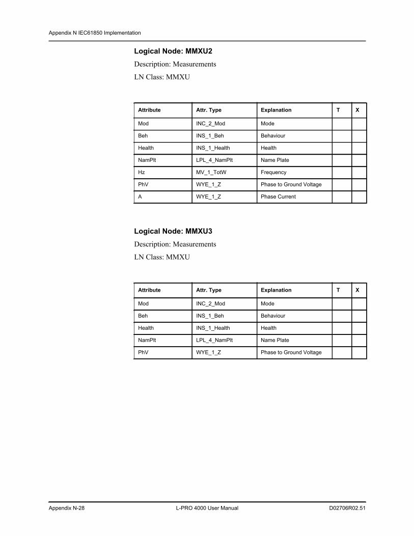
Appendix N IEC61850 Implementation
Appendix N-28 L-PRO 4000 User Manual D02706R02.51
Logical Node: MMXU2Description: Measurements
LN Class: MMXU
Logical Node: MMXU3Description: Measurements
LN Class: MMXU
Attribute Attr. Type Explanation T X
Mod INC_2_Mod Mode
Beh INS_1_Beh Behaviour
Health INS_1_Health Health
NamPlt LPL_4_NamPlt Name Plate
Hz MV_1_TotW Frequency
PhV WYE_1_Z Phase to Ground Voltage
A WYE_1_Z Phase Current
Attribute Attr. Type Explanation T X
Mod INC_2_Mod Mode
Beh INS_1_Beh Behaviour
Health INS_1_Health Health
NamPlt LPL_4_NamPlt Name Plate
PhV WYE_1_Z Phase to Ground Voltage
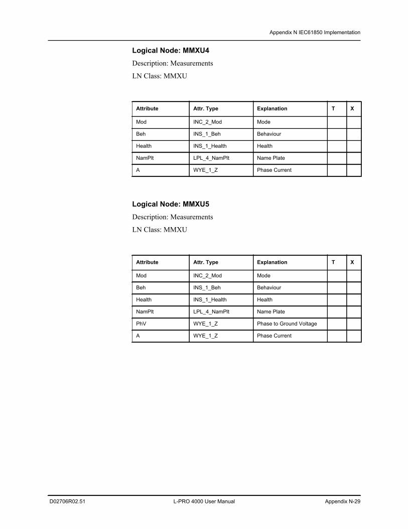
Appendix N IEC61850 Implementation
D02706R02.51 L-PRO 4000 User Manual Appendix N-29
Logical Node: MMXU4Description: Measurements
LN Class: MMXU
Logical Node: MMXU5Description: Measurements
LN Class: MMXU
Attribute Attr. Type Explanation T X
Mod INC_2_Mod Mode
Beh INS_1_Beh Behaviour
Health INS_1_Health Health
NamPlt LPL_4_NamPlt Name Plate
A WYE_1_Z Phase Current
Attribute Attr. Type Explanation T X
Mod INC_2_Mod Mode
Beh INS_1_Beh Behaviour
Health INS_1_Health Health
NamPlt LPL_4_NamPlt Name Plate
PhV WYE_1_Z Phase to Ground Voltage
A WYE_1_Z Phase Current
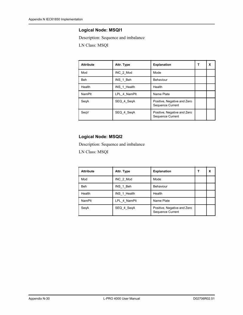
Appendix N IEC61850 Implementation
Appendix N-30 L-PRO 4000 User Manual D02706R02.51
Logical Node: MSQI1Description: Sequence and imbalance
LN Class: MSQI
Logical Node: MSQI2Description: Sequence and imbalance
LN Class: MSQI
Attribute Attr. Type Explanation T X
Mod INC_2_Mod Mode
Beh INS_1_Beh Behaviour
Health INS_1_Health Health
NamPlt LPL_4_NamPlt Name Plate
SeqA SEQ_4_SeqA Positive, Negative and Zero Sequence Current
SeqV SEQ_4_SeqA Positive, Negative and Zero Sequence Current
Attribute Attr. Type Explanation T X
Mod INC_2_Mod Mode
Beh INS_1_Beh Behaviour
Health INS_1_Health Health
NamPlt LPL_4_NamPlt Name Plate
SeqA SEQ_4_SeqA Positive, Negative and Zero Sequence Current
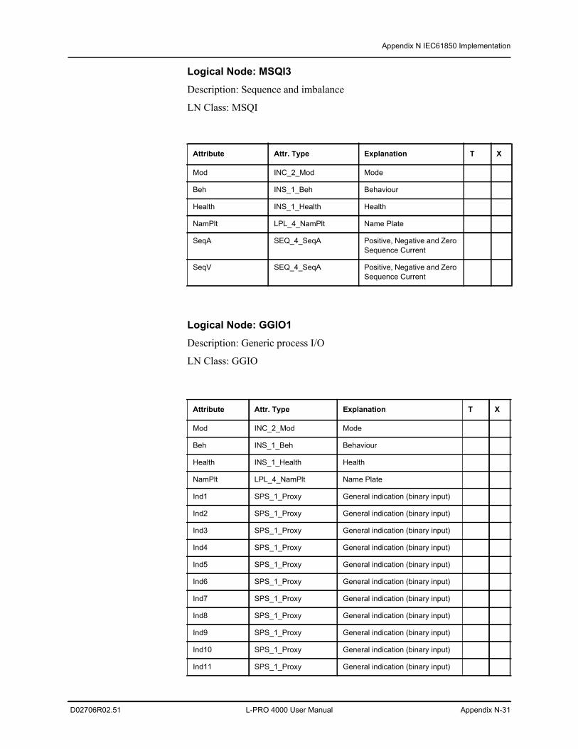
Appendix N IEC61850 Implementation
D02706R02.51 L-PRO 4000 User Manual Appendix N-31
Logical Node: MSQI3Description: Sequence and imbalance
LN Class: MSQI
Logical Node: GGIO1Description: Generic process I/O
LN Class: GGIO
Attribute Attr. Type Explanation T X
Mod INC_2_Mod Mode
Beh INS_1_Beh Behaviour
Health INS_1_Health Health
NamPlt LPL_4_NamPlt Name Plate
SeqA SEQ_4_SeqA Positive, Negative and Zero Sequence Current
SeqV SEQ_4_SeqA Positive, Negative and Zero Sequence Current
Attribute Attr. Type Explanation T X
Mod INC_2_Mod Mode
Beh INS_1_Beh Behaviour
Health INS_1_Health Health
NamPlt LPL_4_NamPlt Name Plate
Ind1 SPS_1_Proxy General indication (binary input)
Ind2 SPS_1_Proxy General indication (binary input)
Ind3 SPS_1_Proxy General indication (binary input)
Ind4 SPS_1_Proxy General indication (binary input)
Ind5 SPS_1_Proxy General indication (binary input)
Ind6 SPS_1_Proxy General indication (binary input)
Ind7 SPS_1_Proxy General indication (binary input)
Ind8 SPS_1_Proxy General indication (binary input)
Ind9 SPS_1_Proxy General indication (binary input)
Ind10 SPS_1_Proxy General indication (binary input)
Ind11 SPS_1_Proxy General indication (binary input)
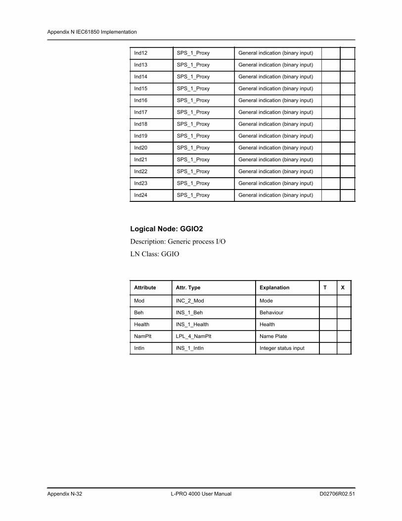
Appendix N IEC61850 Implementation
Appendix N-32 L-PRO 4000 User Manual D02706R02.51
Logical Node: GGIO2Description: Generic process I/O
LN Class: GGIO
Ind12 SPS_1_Proxy General indication (binary input)
Ind13 SPS_1_Proxy General indication (binary input)
Ind14 SPS_1_Proxy General indication (binary input)
Ind15 SPS_1_Proxy General indication (binary input)
Ind16 SPS_1_Proxy General indication (binary input)
Ind17 SPS_1_Proxy General indication (binary input)
Ind18 SPS_1_Proxy General indication (binary input)
Ind19 SPS_1_Proxy General indication (binary input)
Ind20 SPS_1_Proxy General indication (binary input)
Ind21 SPS_1_Proxy General indication (binary input)
Ind22 SPS_1_Proxy General indication (binary input)
Ind23 SPS_1_Proxy General indication (binary input)
Ind24 SPS_1_Proxy General indication (binary input)
Attribute Attr. Type Explanation T X
Mod INC_2_Mod Mode
Beh INS_1_Beh Behaviour
Health INS_1_Health Health
NamPlt LPL_4_NamPlt Name Plate
IntIn INS_1_IntIn Integer status input
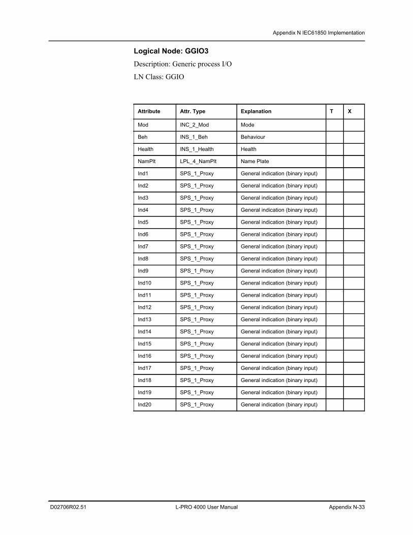
Appendix N IEC61850 Implementation
D02706R02.51 L-PRO 4000 User Manual Appendix N-33
Logical Node: GGIO3Description: Generic process I/O
LN Class: GGIO
Attribute Attr. Type Explanation T X
Mod INC_2_Mod Mode
Beh INS_1_Beh Behaviour
Health INS_1_Health Health
NamPlt LPL_4_NamPlt Name Plate
Ind1 SPS_1_Proxy General indication (binary input)
Ind2 SPS_1_Proxy General indication (binary input)
Ind3 SPS_1_Proxy General indication (binary input)
Ind4 SPS_1_Proxy General indication (binary input)
Ind5 SPS_1_Proxy General indication (binary input)
Ind6 SPS_1_Proxy General indication (binary input)
Ind7 SPS_1_Proxy General indication (binary input)
Ind8 SPS_1_Proxy General indication (binary input)
Ind9 SPS_1_Proxy General indication (binary input)
Ind10 SPS_1_Proxy General indication (binary input)
Ind11 SPS_1_Proxy General indication (binary input)
Ind12 SPS_1_Proxy General indication (binary input)
Ind13 SPS_1_Proxy General indication (binary input)
Ind14 SPS_1_Proxy General indication (binary input)
Ind15 SPS_1_Proxy General indication (binary input)
Ind16 SPS_1_Proxy General indication (binary input)
Ind17 SPS_1_Proxy General indication (binary input)
Ind18 SPS_1_Proxy General indication (binary input)
Ind19 SPS_1_Proxy General indication (binary input)
Ind20 SPS_1_Proxy General indication (binary input)
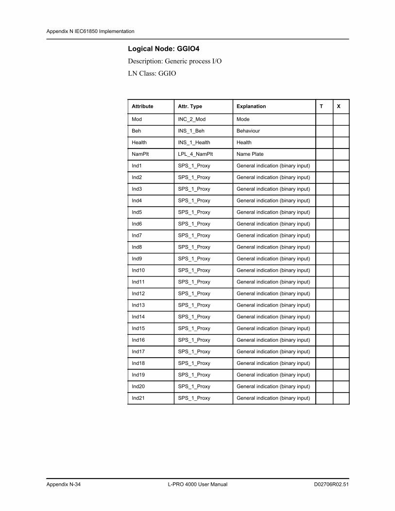
Appendix N IEC61850 Implementation
Appendix N-34 L-PRO 4000 User Manual D02706R02.51
Logical Node: GGIO4Description: Generic process I/O
LN Class: GGIO
Attribute Attr. Type Explanation T X
Mod INC_2_Mod Mode
Beh INS_1_Beh Behaviour
Health INS_1_Health Health
NamPlt LPL_4_NamPlt Name Plate
Ind1 SPS_1_Proxy General indication (binary input)
Ind2 SPS_1_Proxy General indication (binary input)
Ind3 SPS_1_Proxy General indication (binary input)
Ind4 SPS_1_Proxy General indication (binary input)
Ind5 SPS_1_Proxy General indication (binary input)
Ind6 SPS_1_Proxy General indication (binary input)
Ind7 SPS_1_Proxy General indication (binary input)
Ind8 SPS_1_Proxy General indication (binary input)
Ind9 SPS_1_Proxy General indication (binary input)
Ind10 SPS_1_Proxy General indication (binary input)
Ind11 SPS_1_Proxy General indication (binary input)
Ind12 SPS_1_Proxy General indication (binary input)
Ind13 SPS_1_Proxy General indication (binary input)
Ind14 SPS_1_Proxy General indication (binary input)
Ind15 SPS_1_Proxy General indication (binary input)
Ind16 SPS_1_Proxy General indication (binary input)
Ind17 SPS_1_Proxy General indication (binary input)
Ind18 SPS_1_Proxy General indication (binary input)
Ind19 SPS_1_Proxy General indication (binary input)
Ind20 SPS_1_Proxy General indication (binary input)
Ind21 SPS_1_Proxy General indication (binary input)
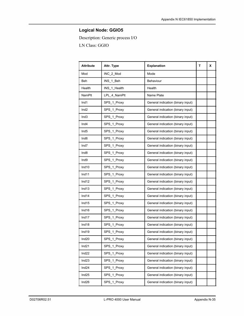
Appendix N IEC61850 Implementation
D02706R02.51 L-PRO 4000 User Manual Appendix N-35
Logical Node: GGIO5Description: Generic process I/O
LN Class: GGIO
Attribute Attr. Type Explanation T X
Mod INC_2_Mod Mode
Beh INS_1_Beh Behaviour
Health INS_1_Health Health
NamPlt LPL_4_NamPlt Name Plate
Ind1 SPS_1_Proxy General indication (binary input)
Ind2 SPS_1_Proxy General indication (binary input)
Ind3 SPS_1_Proxy General indication (binary input)
Ind4 SPS_1_Proxy General indication (binary input)
Ind5 SPS_1_Proxy General indication (binary input)
Ind6 SPS_1_Proxy General indication (binary input)
Ind7 SPS_1_Proxy General indication (binary input)
Ind8 SPS_1_Proxy General indication (binary input)
Ind9 SPS_1_Proxy General indication (binary input)
Ind10 SPS_1_Proxy General indication (binary input)
Ind11 SPS_1_Proxy General indication (binary input)
Ind12 SPS_1_Proxy General indication (binary input)
Ind13 SPS_1_Proxy General indication (binary input)
Ind14 SPS_1_Proxy General indication (binary input)
Ind15 SPS_1_Proxy General indication (binary input)
Ind16 SPS_1_Proxy General indication (binary input)
Ind17 SPS_1_Proxy General indication (binary input)
Ind18 SPS_1_Proxy General indication (binary input)
Ind19 SPS_1_Proxy General indication (binary input)
Ind20 SPS_1_Proxy General indication (binary input)
Ind21 SPS_1_Proxy General indication (binary input)
Ind22 SPS_1_Proxy General indication (binary input)
Ind23 SPS_1_Proxy General indication (binary input)
Ind24 SPS_1_Proxy General indication (binary input)
Ind25 SPS_1_Proxy General indication (binary input)
Ind26 SPS_1_Proxy General indication (binary input)
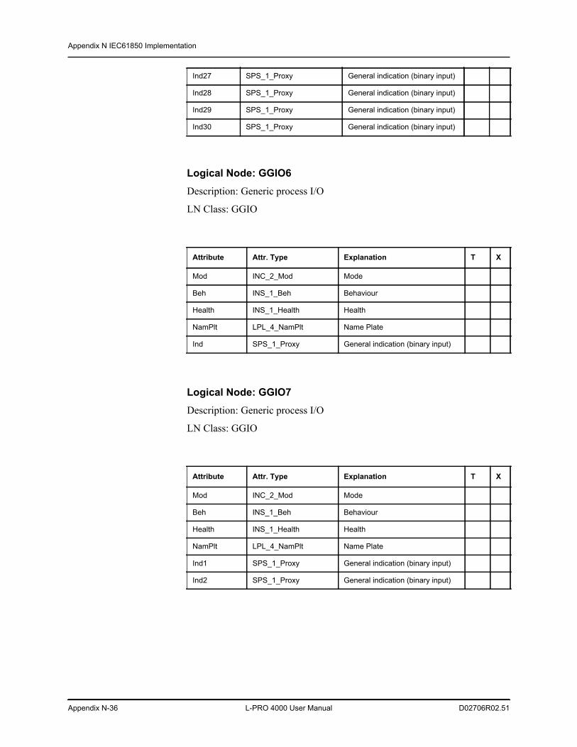
Appendix N IEC61850 Implementation
Appendix N-36 L-PRO 4000 User Manual D02706R02.51
Logical Node: GGIO6Description: Generic process I/O
LN Class: GGIO
Logical Node: GGIO7Description: Generic process I/O
LN Class: GGIO
Ind27 SPS_1_Proxy General indication (binary input)
Ind28 SPS_1_Proxy General indication (binary input)
Ind29 SPS_1_Proxy General indication (binary input)
Ind30 SPS_1_Proxy General indication (binary input)
Attribute Attr. Type Explanation T X
Mod INC_2_Mod Mode
Beh INS_1_Beh Behaviour
Health INS_1_Health Health
NamPlt LPL_4_NamPlt Name Plate
Ind SPS_1_Proxy General indication (binary input)
Attribute Attr. Type Explanation T X
Mod INC_2_Mod Mode
Beh INS_1_Beh Behaviour
Health INS_1_Health Health
NamPlt LPL_4_NamPlt Name Plate
Ind1 SPS_1_Proxy General indication (binary input)
Ind2 SPS_1_Proxy General indication (binary input)
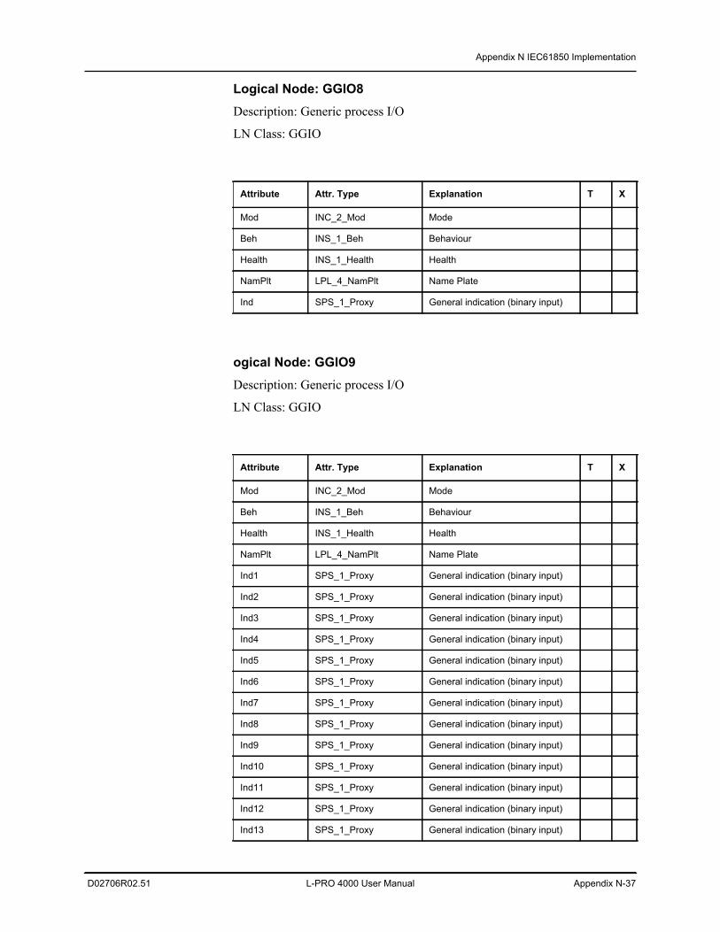
Appendix N IEC61850 Implementation
D02706R02.51 L-PRO 4000 User Manual Appendix N-37
Logical Node: GGIO8Description: Generic process I/O
LN Class: GGIO
ogical Node: GGIO9Description: Generic process I/O
LN Class: GGIO
Attribute Attr. Type Explanation T X
Mod INC_2_Mod Mode
Beh INS_1_Beh Behaviour
Health INS_1_Health Health
NamPlt LPL_4_NamPlt Name Plate
Ind SPS_1_Proxy General indication (binary input)
Attribute Attr. Type Explanation T X
Mod INC_2_Mod Mode
Beh INS_1_Beh Behaviour
Health INS_1_Health Health
NamPlt LPL_4_NamPlt Name Plate
Ind1 SPS_1_Proxy General indication (binary input)
Ind2 SPS_1_Proxy General indication (binary input)
Ind3 SPS_1_Proxy General indication (binary input)
Ind4 SPS_1_Proxy General indication (binary input)
Ind5 SPS_1_Proxy General indication (binary input)
Ind6 SPS_1_Proxy General indication (binary input)
Ind7 SPS_1_Proxy General indication (binary input)
Ind8 SPS_1_Proxy General indication (binary input)
Ind9 SPS_1_Proxy General indication (binary input)
Ind10 SPS_1_Proxy General indication (binary input)
Ind11 SPS_1_Proxy General indication (binary input)
Ind12 SPS_1_Proxy General indication (binary input)
Ind13 SPS_1_Proxy General indication (binary input)
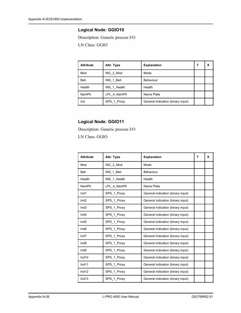
Appendix N IEC61850 Implementation
Appendix N-38 L-PRO 4000 User Manual D02706R02.51
Logical Node: GGIO10Description: Generic process I/O
LN Class: GGIO
Logical Node: GGIO11Description: Generic process I/O
LN Class: GGIO
Attribute Attr. Type Explanation T X
Mod INC_2_Mod Mode
Beh INS_1_Beh Behaviour
Health INS_1_Health Health
NamPlt LPL_4_NamPlt Name Plate
Ind SPS_1_Proxy General indication (binary input)
Attribute Attr. Type Explanation T X
Mod INC_2_Mod Mode
Beh INS_1_Beh Behaviour
Health INS_1_Health Health
NamPlt LPL_4_NamPlt Name Plate
Ind1 SPS_1_Proxy General indication (binary input)
Ind2 SPS_1_Proxy General indication (binary input)
Ind3 SPS_1_Proxy General indication (binary input)
Ind4 SPS_1_Proxy General indication (binary input)
Ind5 SPS_1_Proxy General indication (binary input)
Ind6 SPS_1_Proxy General indication (binary input)
Ind7 SPS_1_Proxy General indication (binary input)
Ind8 SPS_1_Proxy General indication (binary input)
Ind9 SPS_1_Proxy General indication (binary input)
Ind10 SPS_1_Proxy General indication (binary input)
Ind11 SPS_1_Proxy General indication (binary input)
Ind12 SPS_1_Proxy General indication (binary input)
Ind13 SPS_1_Proxy General indication (binary input)
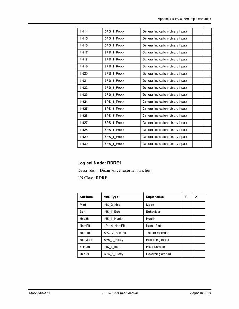
Appendix N IEC61850 Implementation
D02706R02.51 L-PRO 4000 User Manual Appendix N-39
Logical Node: RDRE1Description: Disturbance recorder function
LN Class: RDRE
Ind14 SPS_1_Proxy General indication (binary input)
Ind15 SPS_1_Proxy General indication (binary input)
Ind16 SPS_1_Proxy General indication (binary input)
Ind17 SPS_1_Proxy General indication (binary input)
Ind18 SPS_1_Proxy General indication (binary input)
Ind19 SPS_1_Proxy General indication (binary input)
Ind20 SPS_1_Proxy General indication (binary input)
Ind21 SPS_1_Proxy General indication (binary input)
Ind22 SPS_1_Proxy General indication (binary input)
Ind23 SPS_1_Proxy General indication (binary input)
Ind24 SPS_1_Proxy General indication (binary input)
Ind25 SPS_1_Proxy General indication (binary input)
Ind26 SPS_1_Proxy General indication (binary input)
Ind27 SPS_1_Proxy General indication (binary input)
Ind28 SPS_1_Proxy General indication (binary input)
Ind29 SPS_1_Proxy General indication (binary input)
Ind30 SPS_1_Proxy General indication (binary input)
Attribute Attr. Type Explanation T X
Mod INC_2_Mod Mode
Beh INS_1_Beh Behaviour
Health INS_1_Health Health
NamPlt LPL_4_NamPlt Name Plate
RcdTrg SPC_2_RcdTrg Trigger recorder
RcdMade SPS_1_Proxy Recording made
FltNum INS_1_IntIn Fault Number
RcdStr SPS_1_Proxy Recording started
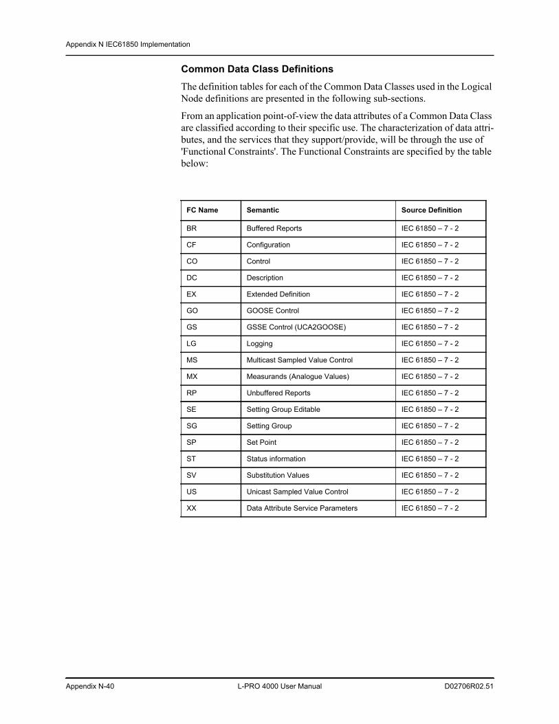
Appendix N IEC61850 Implementation
Appendix N-40 L-PRO 4000 User Manual D02706R02.51
Common Data Class DefinitionsThe definition tables for each of the Common Data Classes used in the Logical Node definitions are presented in the following sub-sections.
From an application point-of-view the data attributes of a Common Data Class are classified according to their specific use. The characterization of data attri-butes, and the services that they support/provide, will be through the use of 'Functional Constraints'. The Functional Constraints are specified by the table below:
FC Name Semantic Source Definition
BR Buffered Reports IEC 61850 – 7 - 2
CF Configuration IEC 61850 – 7 - 2
CO Control IEC 61850 – 7 - 2
DC Description IEC 61850 – 7 - 2
EX Extended Definition IEC 61850 – 7 - 2
GO GOOSE Control IEC 61850 – 7 - 2
GS GSSE Control (UCA2GOOSE) IEC 61850 – 7 - 2
LG Logging IEC 61850 – 7 - 2
MS Multicast Sampled Value Control IEC 61850 – 7 - 2
MX Measurands (Analogue Values) IEC 61850 – 7 - 2
RP Unbuffered Reports IEC 61850 – 7 - 2
SE Setting Group Editable IEC 61850 – 7 - 2
SG Setting Group IEC 61850 – 7 - 2
SP Set Point IEC 61850 – 7 - 2
ST Status information IEC 61850 – 7 - 2
SV Substitution Values IEC 61850 – 7 - 2
US Unicast Sampled Value Control IEC 61850 – 7 - 2
XX Data Attribute Service Parameters IEC 61850 – 7 - 2
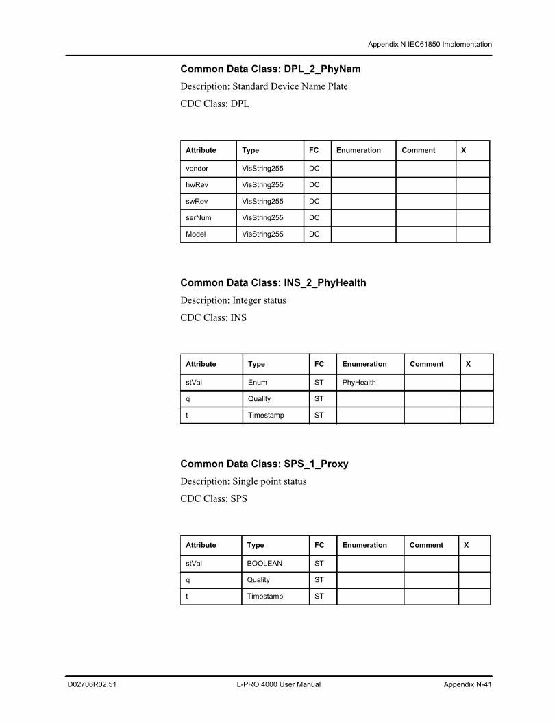
Appendix N IEC61850 Implementation
D02706R02.51 L-PRO 4000 User Manual Appendix N-41
Common Data Class: DPL_2_PhyNamDescription: Standard Device Name Plate
CDC Class: DPL
Common Data Class: INS_2_PhyHealthDescription: Integer status
CDC Class: INS
Common Data Class: SPS_1_ProxyDescription: Single point status
CDC Class: SPS
Attribute Type FC Enumeration Comment X
vendor VisString255 DC
hwRev VisString255 DC
swRev VisString255 DC
serNum VisString255 DC
Model VisString255 DC
Attribute Type FC Enumeration Comment X
stVal Enum ST PhyHealth
q Quality ST
t Timestamp ST
Attribute Type FC Enumeration Comment X
stVal BOOLEAN ST
q Quality ST
t Timestamp ST
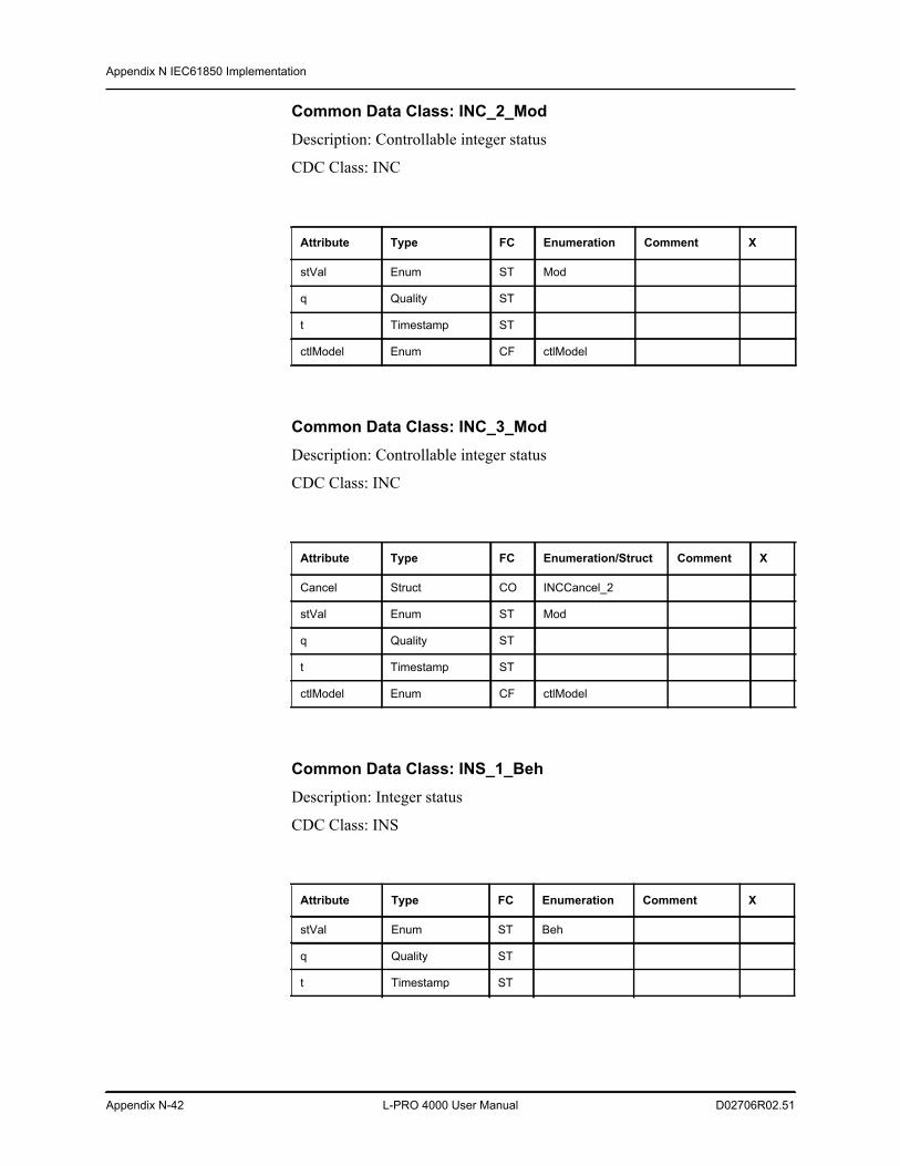
Appendix N IEC61850 Implementation
Appendix N-42 L-PRO 4000 User Manual D02706R02.51
Common Data Class: INC_2_ModDescription: Controllable integer status
CDC Class: INC
Common Data Class: INC_3_ModDescription: Controllable integer status
CDC Class: INC
Common Data Class: INS_1_BehDescription: Integer status
CDC Class: INS
Attribute Type FC Enumeration Comment X
stVal Enum ST Mod
q Quality ST
t Timestamp ST
ctlModel Enum CF ctlModel
Attribute Type FC Enumeration/Struct Comment X
Cancel Struct CO INCCancel_2
stVal Enum ST Mod
q Quality ST
t Timestamp ST
ctlModel Enum CF ctlModel
Attribute Type FC Enumeration Comment X
stVal Enum ST Beh
q Quality ST
t Timestamp ST
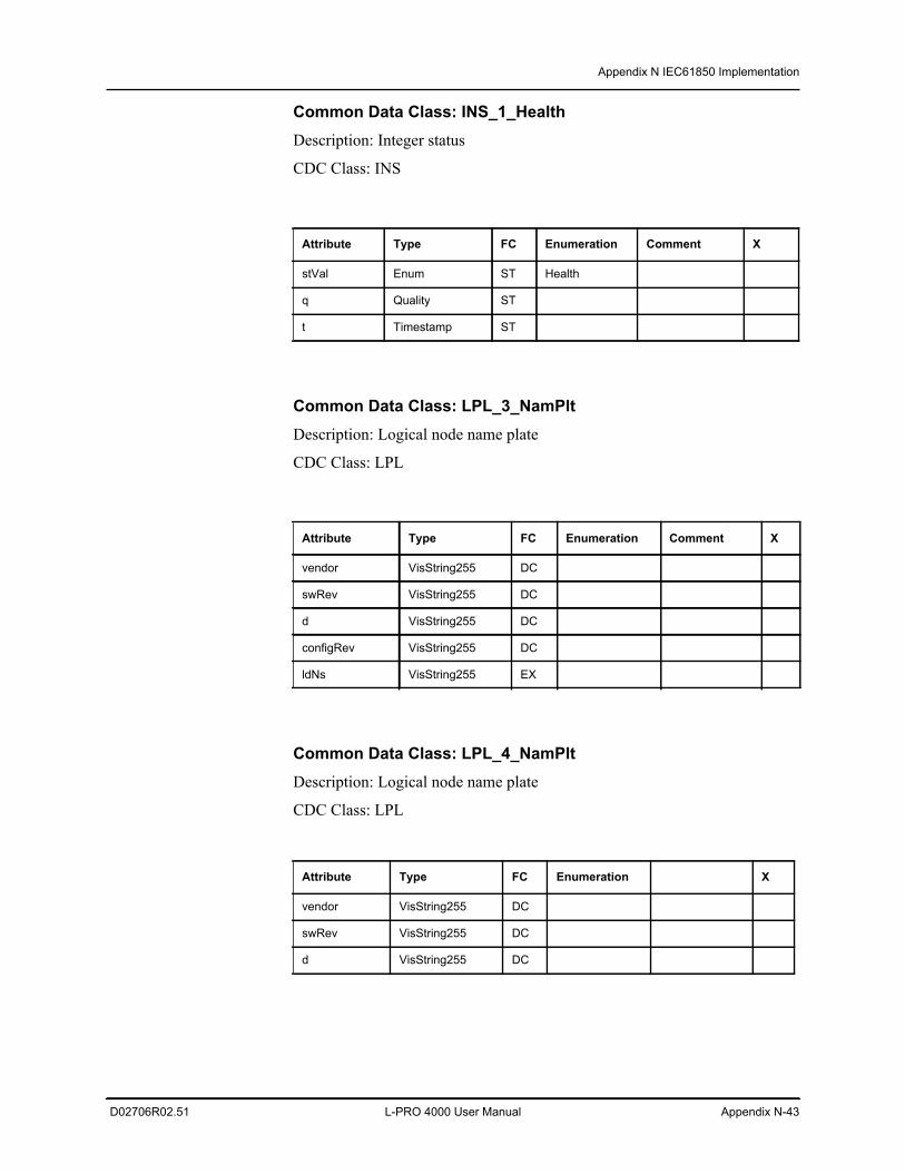
Appendix N IEC61850 Implementation
D02706R02.51 L-PRO 4000 User Manual Appendix N-43
Common Data Class: INS_1_HealthDescription: Integer status
CDC Class: INS
Common Data Class: LPL_3_NamPltDescription: Logical node name plate
CDC Class: LPL
Common Data Class: LPL_4_NamPltDescription: Logical node name plate
CDC Class: LPL
Attribute Type FC Enumeration Comment X
stVal Enum ST Health
q Quality ST
t Timestamp ST
Attribute Type FC Enumeration Comment X
vendor VisString255 DC
swRev VisString255 DC
d VisString255 DC
configRev VisString255 DC
ldNs VisString255 EX
Attribute Type FC Enumeration X
vendor VisString255 DC
swRev VisString255 DC
d VisString255 DC
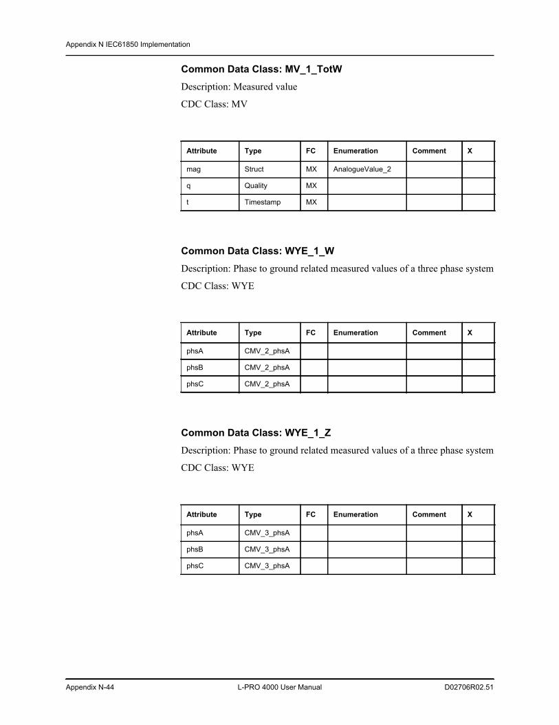
Appendix N IEC61850 Implementation
Appendix N-44 L-PRO 4000 User Manual D02706R02.51
Common Data Class: MV_1_TotWDescription: Measured value
CDC Class: MV
Common Data Class: WYE_1_WDescription: Phase to ground related measured values of a three phase system
CDC Class: WYE
Common Data Class: WYE_1_ZDescription: Phase to ground related measured values of a three phase system
CDC Class: WYE
Attribute Type FC Enumeration Comment X
mag Struct MX AnalogueValue_2
q Quality MX
t Timestamp MX
Attribute Type FC Enumeration Comment X
phsA CMV_2_phsA
phsB CMV_2_phsA
phsC CMV_2_phsA
Attribute Type FC Enumeration Comment X
phsA CMV_3_phsA
phsB CMV_3_phsA
phsC CMV_3_phsA
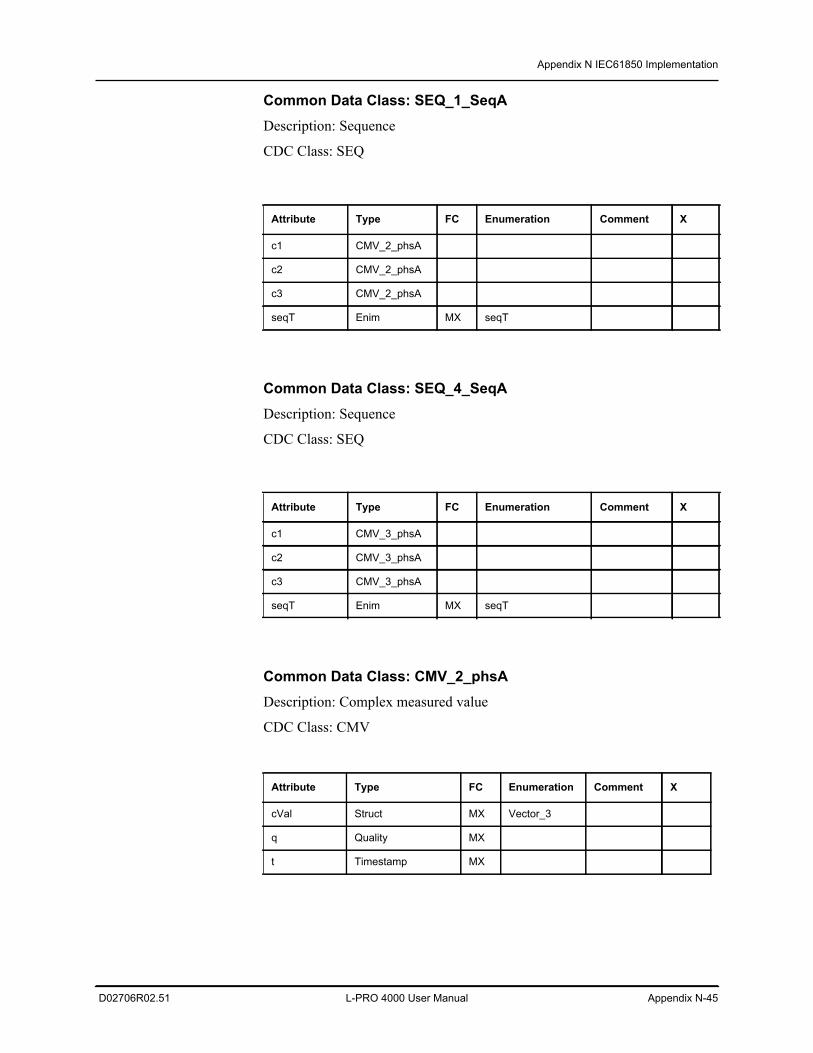
Appendix N IEC61850 Implementation
D02706R02.51 L-PRO 4000 User Manual Appendix N-45
Common Data Class: SEQ_1_SeqADescription: Sequence
CDC Class: SEQ
Common Data Class: SEQ_4_SeqADescription: Sequence
CDC Class: SEQ
Common Data Class: CMV_2_phsADescription: Complex measured value
CDC Class: CMV
Attribute Type FC Enumeration Comment X
c1 CMV_2_phsA
c2 CMV_2_phsA
c3 CMV_2_phsA
seqT Enim MX seqT
Attribute Type FC Enumeration Comment X
c1 CMV_3_phsA
c2 CMV_3_phsA
c3 CMV_3_phsA
seqT Enim MX seqT
Attribute Type FC Enumeration Comment X
cVal Struct MX Vector_3
q Quality MX
t Timestamp MX
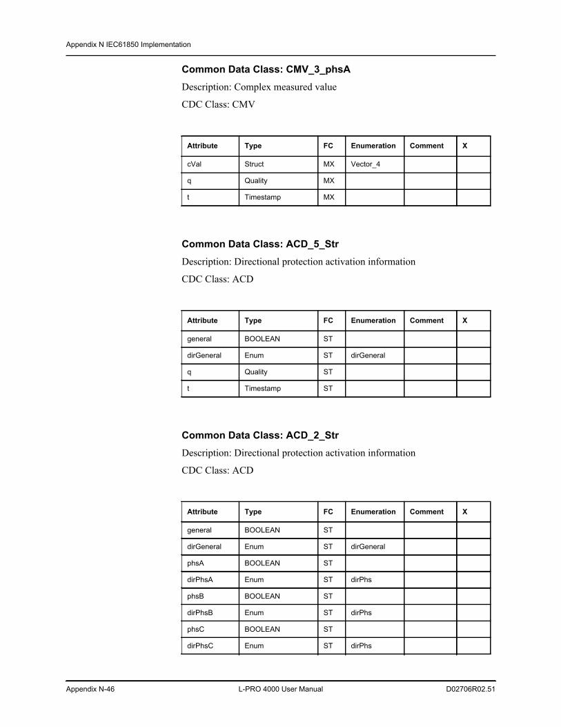
Appendix N IEC61850 Implementation
Appendix N-46 L-PRO 4000 User Manual D02706R02.51
Common Data Class: CMV_3_phsADescription: Complex measured value
CDC Class: CMV
Common Data Class: ACD_5_StrDescription: Directional protection activation information
CDC Class: ACD
Common Data Class: ACD_2_StrDescription: Directional protection activation information
CDC Class: ACD
Attribute Type FC Enumeration Comment X
cVal Struct MX Vector_4
q Quality MX
t Timestamp MX
Attribute Type FC Enumeration Comment X
general BOOLEAN ST
dirGeneral Enum ST dirGeneral
q Quality ST
t Timestamp ST
Attribute Type FC Enumeration Comment X
general BOOLEAN ST
dirGeneral Enum ST dirGeneral
phsA BOOLEAN ST
dirPhsA Enum ST dirPhs
phsB BOOLEAN ST
dirPhsB Enum ST dirPhs
phsC BOOLEAN ST
dirPhsC Enum ST dirPhs
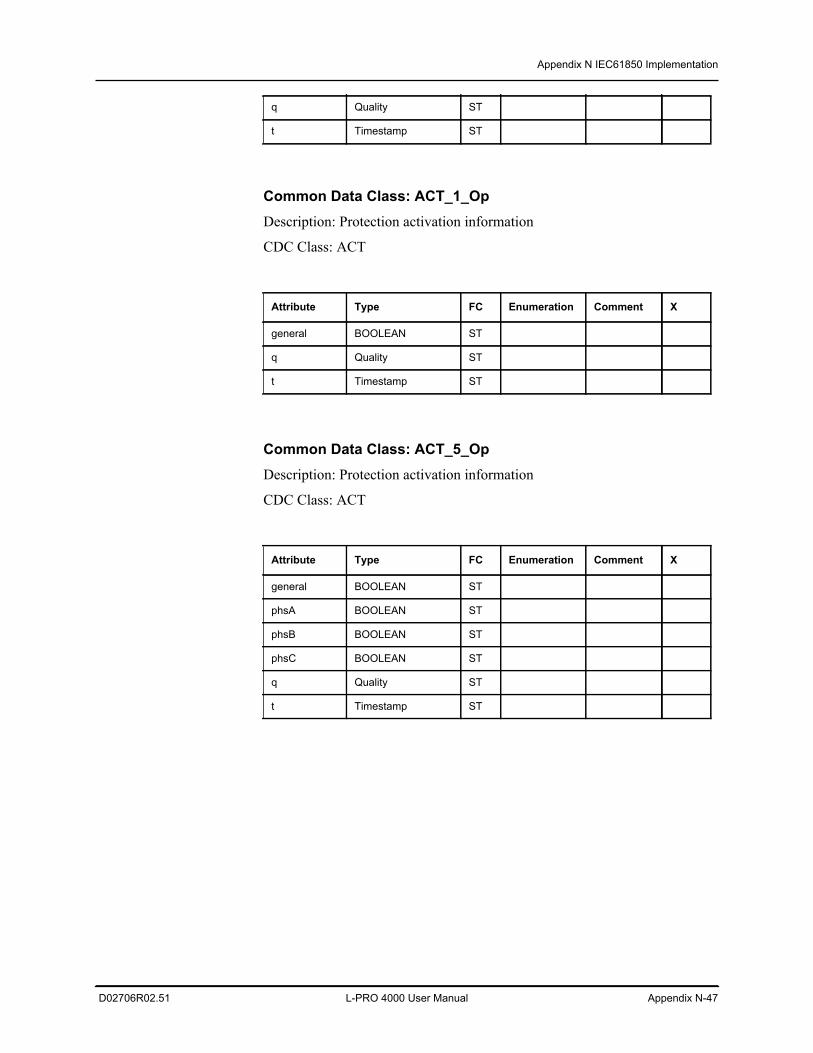
Appendix N IEC61850 Implementation
D02706R02.51 L-PRO 4000 User Manual Appendix N-47
Common Data Class: ACT_1_OpDescription: Protection activation information
CDC Class: ACT
Common Data Class: ACT_5_OpDescription: Protection activation information
CDC Class: ACT
q Quality ST
t Timestamp ST
Attribute Type FC Enumeration Comment X
general BOOLEAN ST
q Quality ST
t Timestamp ST
Attribute Type FC Enumeration Comment X
general BOOLEAN ST
phsA BOOLEAN ST
phsB BOOLEAN ST
phsC BOOLEAN ST
q Quality ST
t Timestamp ST
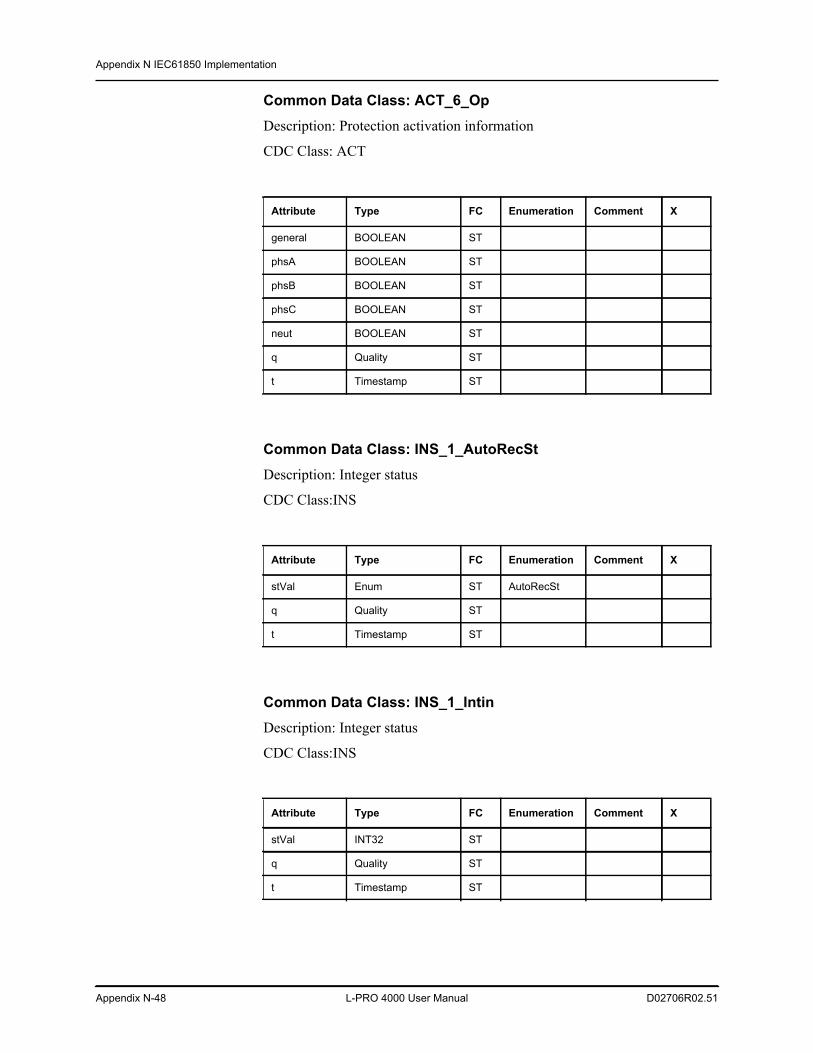
Appendix N IEC61850 Implementation
Appendix N-48 L-PRO 4000 User Manual D02706R02.51
Common Data Class: ACT_6_OpDescription: Protection activation information
CDC Class: ACT
Common Data Class: INS_1_AutoRecStDescription: Integer status
CDC Class:INS
Common Data Class: INS_1_IntinDescription: Integer status
CDC Class:INS
Attribute Type FC Enumeration Comment X
general BOOLEAN ST
phsA BOOLEAN ST
phsB BOOLEAN ST
phsC BOOLEAN ST
neut BOOLEAN ST
q Quality ST
t Timestamp ST
Attribute Type FC Enumeration Comment X
stVal Enum ST AutoRecSt
q Quality ST
t Timestamp ST
Attribute Type FC Enumeration Comment X
stVal INT32 ST
q Quality ST
t Timestamp ST
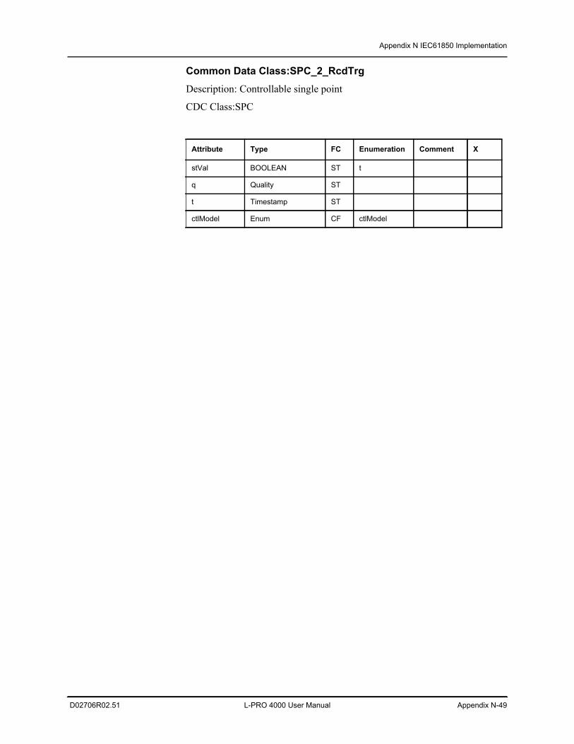
Appendix N IEC61850 Implementation
D02706R02.51 L-PRO 4000 User Manual Appendix N-49
Common Data Class:SPC_2_RcdTrgDescription: Controllable single point
CDC Class:SPC
Attribute Type FC Enumeration Comment X
stVal BOOLEAN ST t
q Quality ST
t Timestamp ST
ctlModel Enum CF ctlModel
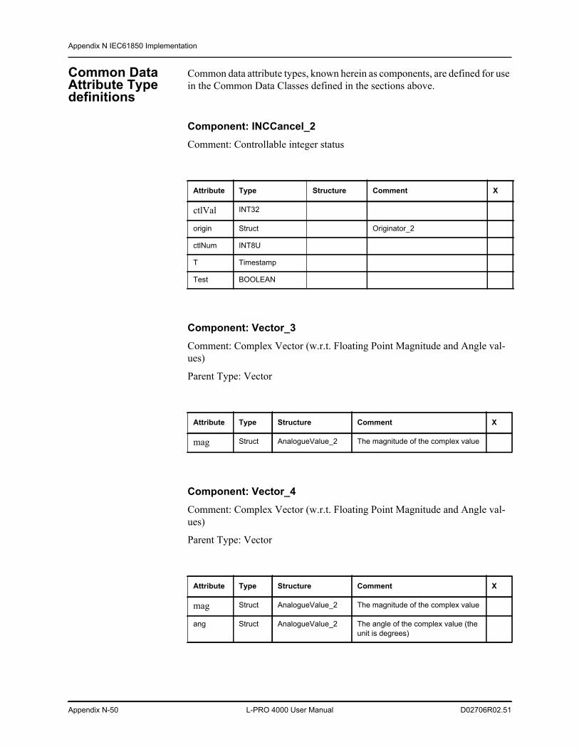
Appendix N IEC61850 Implementation
Appendix N-50 L-PRO 4000 User Manual D02706R02.51
Common Data Attribute Type definitions
Common data attribute types, known herein as components, are defined for use in the Common Data Classes defined in the sections above.
Component: INCCancel_2Comment: Controllable integer status
Component: Vector_3Comment: Complex Vector (w.r.t. Floating Point Magnitude and Angle val-ues)
Parent Type: Vector
Component: Vector_4Comment: Complex Vector (w.r.t. Floating Point Magnitude and Angle val-ues)
Parent Type: Vector
Attribute Type Structure Comment X
ctlVal INT32
origin Struct Originator_2
ctlNum INT8U
T Timestamp
Test BOOLEAN
Attribute Type Structure Comment X
mag Struct AnalogueValue_2 The magnitude of the complex value
Attribute Type Structure Comment X
mag Struct AnalogueValue_2 The magnitude of the complex value
ang Struct AnalogueValue_2 The angle of the complex value (the unit is degrees)
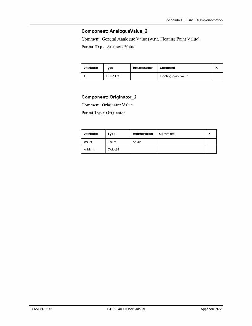
Appendix N IEC61850 Implementation
D02706R02.51 L-PRO 4000 User Manual Appendix N-51
Component: AnalogueValue_2Comment: General Analogue Value (w.r.t. Floating Point Value)
Parent Type: AnalogueValue
Component: Originator_2Comment: Originator Value
Parent Type: Originator
Attribute Type Enumeration Comment X
f FLOAT32 Floating point value
Attribute Type Enumeration Comment X
orCat Enum orCat
orIdent Octet64
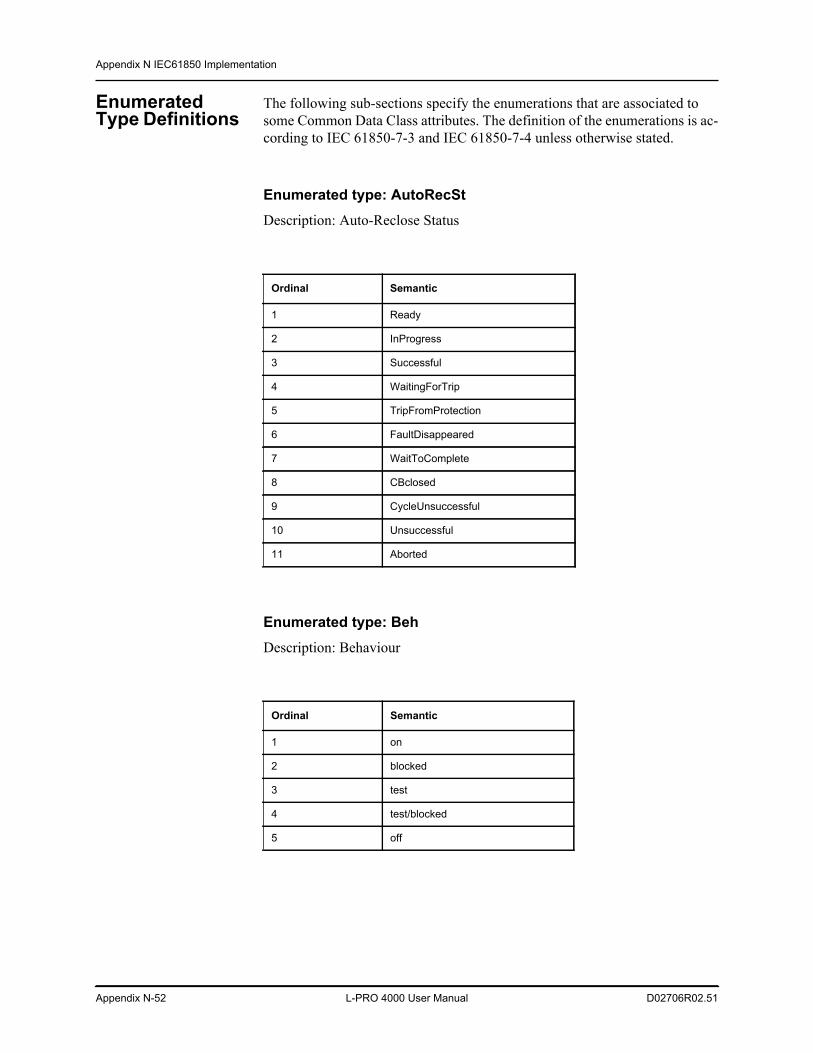
Appendix N IEC61850 Implementation
Appendix N-52 L-PRO 4000 User Manual D02706R02.51
Enumerated Type Definitions
The following sub-sections specify the enumerations that are associated to some Common Data Class attributes. The definition of the enumerations is ac-cording to IEC 61850-7-3 and IEC 61850-7-4 unless otherwise stated.
Enumerated type: AutoRecStDescription: Auto-Reclose Status
Enumerated type: BehDescription: Behaviour
Ordinal Semantic
1 Ready
2 InProgress
3 Successful
4 WaitingForTrip
5 TripFromProtection
6 FaultDisappeared
7 WaitToComplete
8 CBclosed
9 CycleUnsuccessful
10 Unsuccessful
11 Aborted
Ordinal Semantic
1 on
2 blocked
3 test
4 test/blocked
5 off
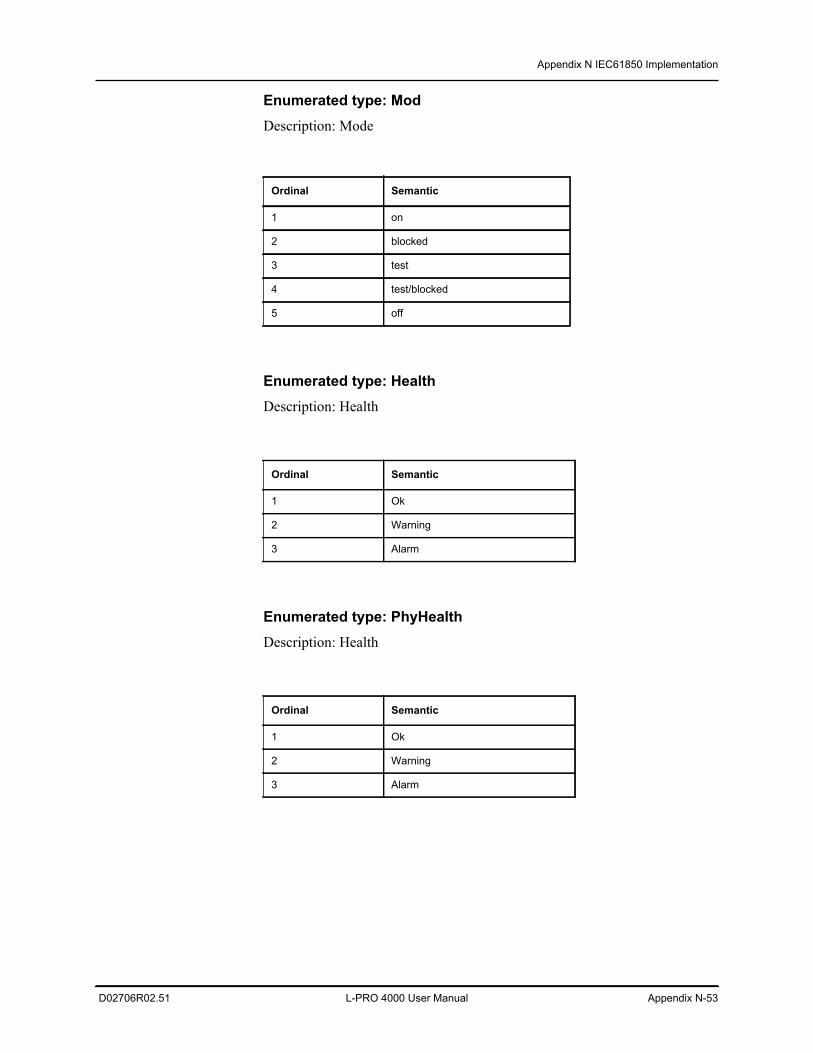
Appendix N IEC61850 Implementation
D02706R02.51 L-PRO 4000 User Manual Appendix N-53
Enumerated type: ModDescription: Mode
Enumerated type: HealthDescription: Health
Enumerated type: PhyHealthDescription: Health
Ordinal Semantic
1 on
2 blocked
3 test
4 test/blocked
5 off
Ordinal Semantic
1 Ok
2 Warning
3 Alarm
Ordinal Semantic
1 Ok
2 Warning
3 Alarm
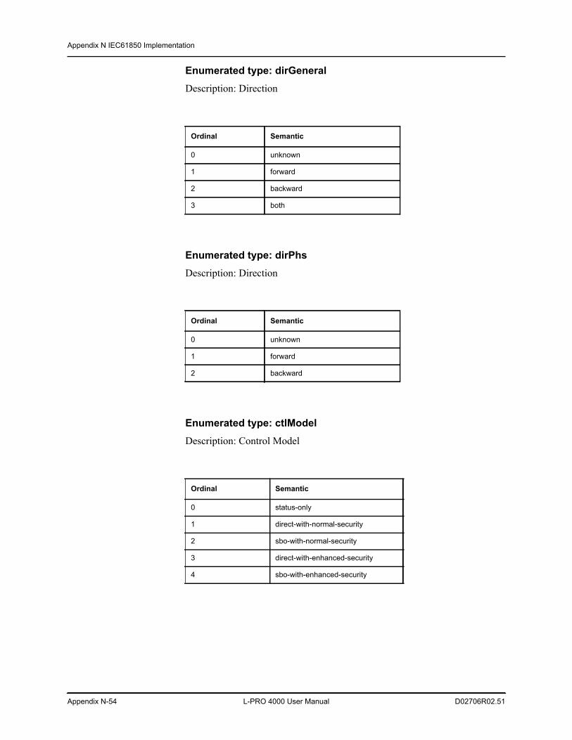
Appendix N IEC61850 Implementation
Appendix N-54 L-PRO 4000 User Manual D02706R02.51
Enumerated type: dirGeneralDescription: Direction
Enumerated type: dirPhsDescription: Direction
Enumerated type: ctlModelDescription: Control Model
Ordinal Semantic
0 unknown
1 forward
2 backward
3 both
Ordinal Semantic
0 unknown
1 forward
2 backward
Ordinal Semantic
0 status-only
1 direct-with-normal-security
2 sbo-with-normal-security
3 direct-with-enhanced-security
4 sbo-with-enhanced-security
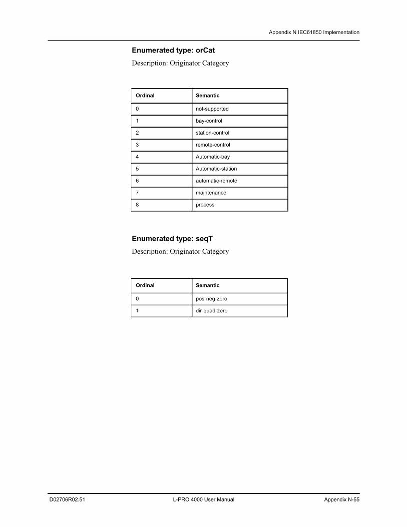
Appendix N IEC61850 Implementation
D02706R02.51 L-PRO 4000 User Manual Appendix N-55
Enumerated type: orCatDescription: Originator Category
Enumerated type: seqTDescription: Originator Category
Ordinal Semantic
0 not-supported
1 bay-control
2 station-control
3 remote-control
4 Automatic-bay
5 Automatic-station
6 automatic-remote
7 maintenance
8 process
Ordinal Semantic
0 pos-neg-zero
1 dir-quad-zero
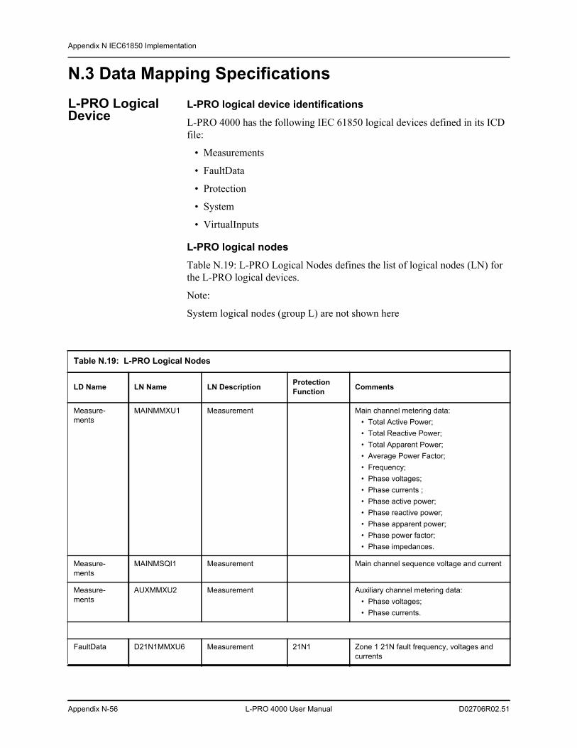
Appendix N IEC61850 Implementation
Appendix N-56 L-PRO 4000 User Manual D02706R02.51
N.3 Data Mapping SpecificationsL-PRO Logical Device
L-PRO logical device identificationsL-PRO 4000 has the following IEC 61850 logical devices defined in its ICD file:
• Measurements
• FaultData
• Protection
• System
• VirtualInputs
L-PRO logical nodesTable N.19: L-PRO Logical Nodes defines the list of logical nodes (LN) for the L-PRO logical devices.
Note:
System logical nodes (group L) are not shown here
Table N.19: L-PRO Logical Nodes
LD Name LN Name LN Description Protection Function Comments
Measure-ments
MAINMMXU1 Measurement Main channel metering data: • Total Active Power; • Total Reactive Power; • Total Apparent Power; • Average Power Factor; • Frequency; • Phase voltages; • Phase currents ; • Phase active power; • Phase reactive power; • Phase apparent power; • Phase power factor; • Phase impedances.
Measure-ments
MAINMSQI1 Measurement Main channel sequence voltage and current
Measure-ments
AUXMMXU2 Measurement Auxiliary channel metering data: • Phase voltages; • Phase currents.
FaultData D21N1MMXU6 Measurement 21N1 Zone 1 21N fault frequency, voltages and currents
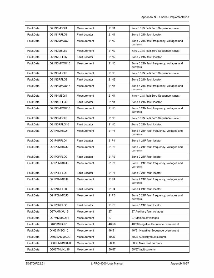
Appendix N IEC61850 Implementation
D02706R02.51 L-PRO 4000 User Manual Appendix N-57
FaultData D21N1MSQI1 Measurement 21N1 Zone 1 21N fault Zero Sequence current
FaultData D21N1RFLO6 Fault Locator 21N1 Zone 1 21N fault locator
FaultData D21N2MMXU7 Measurement 21N2 Zone 2 21N fault frequency, voltages and currents
FaultData D21N2MSQI2 Measurement 21N2 Zone 2 21N fault Zero Sequence current
FaultData D21N2RFLO7 Fault Locator 21N2 Zone 2 21N fault locator
FaultData D21N3MMXU16 Measurement 21N3 Zone 3 21N fault frequency, voltages and currents
FaultData D21N3MSQI3 Measurement 21N3 Zone 3 21N fault Zero Sequence current
FaultData D21N3RFLO8 Fault Locator 21N3 Zone 3 21N fault locator
FaultData D21N4MMXU17 Measurement 21N4 Zone 4 21N fault frequency, voltages and currents
FaultData D21N4MSQI4 Measurement 21N4 Zone 4 21N fault Zero Sequence current
FaultData D21N4RFLO9 Fault Locator 21N4 Zone 4 21N fault locator
FaultData D21N5MMXU10 Measurement 21N5 Zone 5 21N fault frequency, voltages and currents
FaultData D21N5MSQI5 Measurement 21N5 Zone 5 21N fault Zero Sequence current
FaultData D21N5RFLO10 Fault Locator 21N5 Zone 5 21N fault locator
FaultData D21P1MMXU1 Measurement 21P1 Zone 1 21P fault frequency, voltages and currents
FaultData D21P1RFLO1 Fault Locator 21P1 Zone 1 21P fault locator
FaultData D21P2MMXU2 Measurement 21P2 Zone 2 21P fault frequency, voltages and currents
FaultData D21P2RFLO2 Fault Locator 21P2 Zone 2 21P fault locator
FaultData D21P3MMXU3 Measurement 21P3 Zone 3 21P fault frequency, voltages and currents
FaultData D21P3RFLO3 Fault Locator 21P3 Zone 3 21P fault locator
FaultData D21P4MMXU4 Measurement 21P4 Zone 4 21P fault frequency, voltages and currents
FaultData D21P4RFLO4 Fault Locator 21P4 Zone 4 21P fault locator
FaultData D21P5MMXU5 Measurement 21P5 Zone 5 21P fault frequency, voltages and currents
FaultData D21P5RFLO5 Fault Locator 21P5 Zone 5 21P fault locator
FaultData D27AMMXU15 Measurement 27 27 Auxiliary fault voltages
FaultData D27MMMXU14 Measurement 27 27 Main fault voltages
FaultData D4650MSQI7 Measurement 46/50 46/50 Negative Sequence overcurrent
FaultData D4651MSQI10 Measurement 46/51 46/51 Negative Sequence overcurrent
FaultData D50LSAMMXU9 Measurement 50LS 50LS Auxiliary fault currents
FaultData D50LSMMMXU8 Measurement 50LS 50LS Main fault currents
FaultData D5067MMXU18 Measurement 50/67 50/67 fault currents
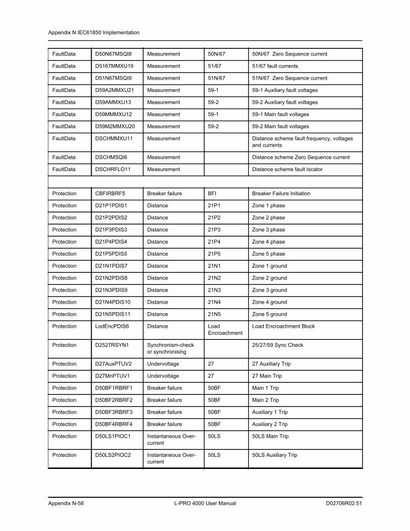
Appendix N IEC61850 Implementation
Appendix N-58 L-PRO 4000 User Manual D02706R02.51
FaultData D50N67MSQI8 Measurement 50N/67 50N/67 Zero Sequence current
FaultData D5167MMXU19 Measurement 51/67 51/67 fault currents
FaultData D51N67MSQI9 Measurement 51N/67 51N/67 Zero Sequence current
FaultData D59A2MMXU21 Measurement 59-1 59-1 Auxiliary fault voltages
FaultData D59AMMXU13 Measurement 59-2 59-2 Auxiliary fault voltages
FaultData D59MMMXU12 Measurement 59-1 59-1 Main fault voltages
FaultData D59M2MMXU20 Measurement 59-2 59-2 Main fault voltages
FaultData DSCHMMXU11 Measurement Distance scheme fault frequency, voltages and currents
FaultData DSCHMSQI6 Measurement Distance scheme Zero Sequence current
FaultData DSCHRFLO11 Measurement Distance scheme fault locator
Protection CBFIRBRF5 Breaker failure BFI Breaker Failure Initiation
Protection D21P1PDIS1 Distance 21P1 Zone 1 phase
Protection D21P2PDIS2 Distance 21P2 Zone 2 phase
Protection D21P3PDIS3 Distance 21P3 Zone 3 phase
Protection D21P4PDIS4 Distance 21P4 Zone 4 phase
Protection D21P5PDIS5 Distance 21P5 Zone 5 phase
Protection D21N1PDIS7 Distance 21N1 Zone 1 ground
Protection D21N2PDIS8 Distance 21N2 Zone 2 ground
Protection D21N3PDIS9 Distance 21N3 Zone 3 ground
Protection D21N4PDIS10 Distance 21N4 Zone 4 ground
Protection D21N5PDIS11 Distance 21N5 Zone 5 ground
Protection LodEncPDIS6 Distance Load Encroachment
Load Encroachment Block
Protection D2527RSYN1 Synchronism-check or synchronising
25/27/59 Sync Check
Protection D27AuxPTUV2 Undervoltage 27 27 Auxiliary Trip
Protection D27MnPTUV1 Undervoltage 27 27 Main Trip
Protection D50BF1RBRF1 Breaker failure 50BF Main 1 Trip
Protection D50BF2RBRF2 Breaker failure 50BF Main 2 Trip
Protection D50BF3RBRF3 Breaker failure 50BF Auxiliary 1 Trip
Protection D50BF4RBRF4 Breaker failure 50BF Auxiliary 2 Trip
Protection D50LS1PIOC1 Instantaneous Over-current
50LS 50LS Main Trip
Protection D50LS2PIOC2 Instantaneous Over-current
50LS 50LS Auxiliary Trip
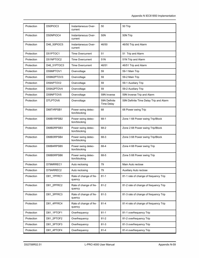
Appendix N IEC61850 Implementation
D02706R02.51 L-PRO 4000 User Manual Appendix N-59
Protection D50PIOC3 Instantaneous Over-current
50 50 Trip
Protection D50NPIOC4 Instantaneous Over-current
50N 50N Trip
Protection D46_50PIOC5 Instantaneous Over-current
46/50 46/50 Trip and Alarm
Protection D51PTOC1 Time Overcurrent 51 51 Trip and Alarm
Protection D51NPTOC2 Time Overcurrent 51N 51N Trip and Alarm
Protection D46_51PTOC3 Time Overcurrent 46/51 46/51 Trip and Alarm
Protection D59MPTOV1 Overvoltage 59 59-1 Main Trip
Protection D59M2PTOV3 Overvoltage 59 59-2 Main Trip
Protection D59APTOV2 Overvoltage 59 59-1 Auxiliary Trip
Protection D59A2PTOV4 Overvoltage 59 59-2 Auxiliary Trip
Protection D59NPTOV5 Overvoltage 59N Inverse 59N Inverse Trip and Alarm
Protection DTLPTOV6 Overvoltage 59N Definite Time Delay
59N Definite Time Delay Trip and Alarm
Protection D68TrRPSB1 Power swing detec-tion/blocking
68 68 Power swing Trip
Protection D68B1RPSB2 Power swing detec-tion/blocking
68-1 Zone 1 68 Power swing Trip/Block
Protection D68B2RPSB3 Power swing detec-tion/blocking
68-2 Zone 2 68 Power swing Trip/Block
Protection D68B3RPSB4 Power swing detec-tion/blocking
68-3 Zone 3 68 Power swing Trip/Block
Protection D68B4RPSB5 Power swing detec-tion/blocking
68-4 Zone 4 68 Power swing Trip
Protection D68B5RPSB6 Power swing detec-tion/blocking
68-5 Zone 5 68 Power swing Trip
Protection D79MRREC1 Auto reclosing 79 Main Auto reclose
Protection D79ARREC2 Auto reclosing 79 Auxiliary Auto reclose
Protection D81_1PFRC1 Rate of change of fre-quency
81-1 81-1 rate of change of frequency Trip
Protection D81_2PFRC2 Rate of change of fre-quency
81-2 81-2 rate of change of frequency Trip
Protection D81_3PFRC3 Rate of change of fre-quency
81-3 81-3 rate of change of frequency Trip
Protection D81_4PFRC4 Rate of change of fre-quency
81-4 81-4 rate of change of frequency Trip
Protection D81_1PTOF1 Overfrequency 81-1 81-1 overfrequency Trip
Protection D81_2PTOF2 Overfrequency 81-2 81-2 overfrequency Trip
Protection D81_3PTOF3 Overfrequency 81-3 81-3 overfrequency Trip
Protection D81_4PTOF4 Overfrequency 81-4 81-4 overfrequency Trip
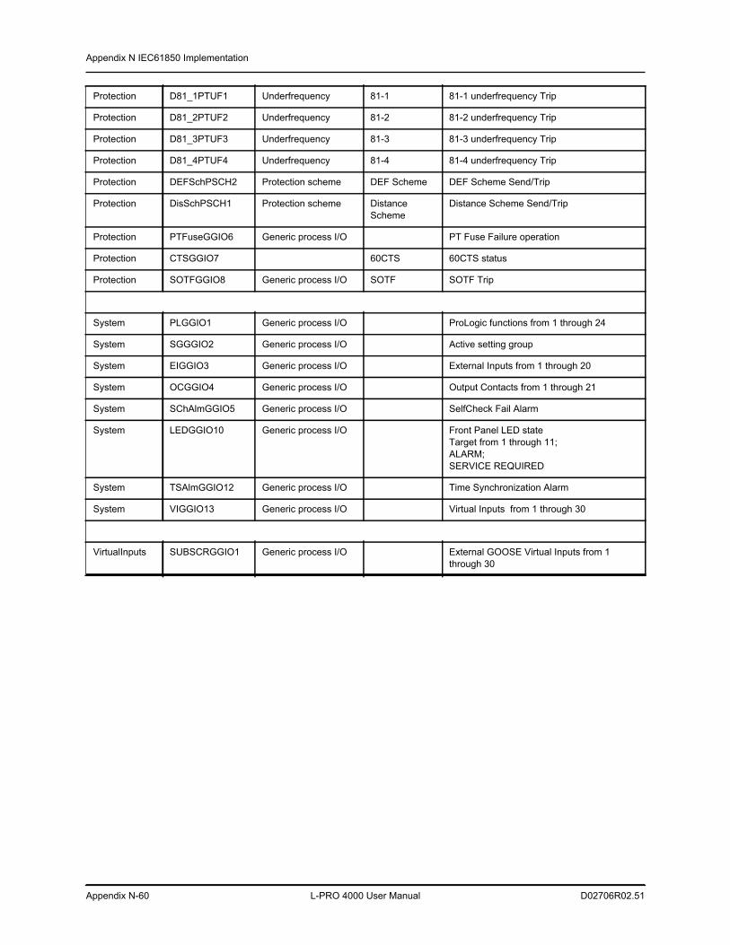
Appendix N IEC61850 Implementation
Appendix N-60 L-PRO 4000 User Manual D02706R02.51
Protection D81_1PTUF1 Underfrequency 81-1 81-1 underfrequency Trip
Protection D81_2PTUF2 Underfrequency 81-2 81-2 underfrequency Trip
Protection D81_3PTUF3 Underfrequency 81-3 81-3 underfrequency Trip
Protection D81_4PTUF4 Underfrequency 81-4 81-4 underfrequency Trip
Protection DEFSchPSCH2 Protection scheme DEF Scheme DEF Scheme Send/Trip
Protection DisSchPSCH1 Protection scheme Distance Scheme
Distance Scheme Send/Trip
Protection PTFuseGGIO6 Generic process I/O PT Fuse Failure operation
Protection CTSGGIO7 60CTS 60CTS status
Protection SOTFGGIO8 Generic process I/O SOTF SOTF Trip
System PLGGIO1 Generic process I/O ProLogic functions from 1 through 24
System SGGGIO2 Generic process I/O Active setting group
System EIGGIO3 Generic process I/O External Inputs from 1 through 20
System OCGGIO4 Generic process I/O Output Contacts from 1 through 21
System SChAlmGGIO5 Generic process I/O SelfCheck Fail Alarm
System LEDGGIO10 Generic process I/O Front Panel LED stateTarget from 1 through 11;ALARM;SERVICE REQUIRED
System TSAlmGGIO12 Generic process I/O Time Synchronization Alarm
System VIGGIO13 Generic process I/O Virtual Inputs from 1 through 30
VirtualInputs SUBSCRGGIO1 Generic process I/O External GOOSE Virtual Inputs from 1 through 30
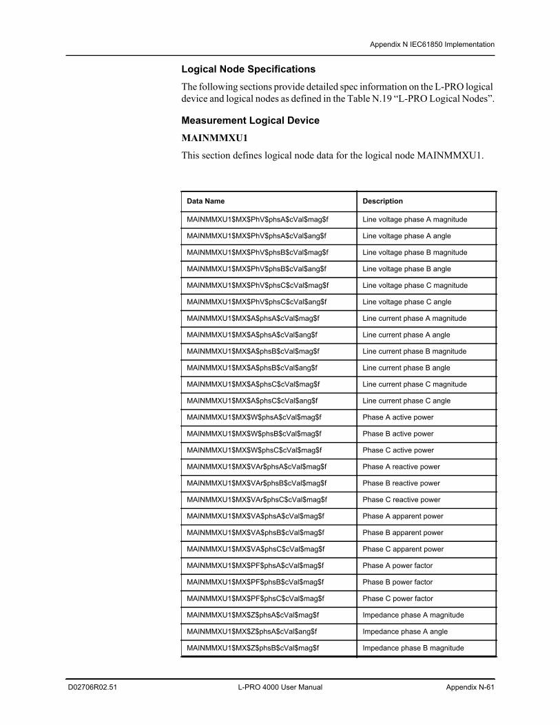
Appendix N IEC61850 Implementation
D02706R02.51 L-PRO 4000 User Manual Appendix N-61
Logical Node SpecificationsThe following sections provide detailed spec information on the L-PRO logical device and logical nodes as defined in the Table N.19 “L-PRO Logical Nodes”.
Measurement Logical Device MAINMMXU1
This section defines logical node data for the logical node MAINMMXU1.
Data Name Description
MAINMMXU1$MX$PhV$phsA$cVal$mag$f Line voltage phase A magnitude
MAINMMXU1$MX$PhV$phsA$cVal$ang$f Line voltage phase A angle
MAINMMXU1$MX$PhV$phsB$cVal$mag$f Line voltage phase B magnitude
MAINMMXU1$MX$PhV$phsB$cVal$ang$f Line voltage phase B angle
MAINMMXU1$MX$PhV$phsC$cVal$mag$f Line voltage phase C magnitude
MAINMMXU1$MX$PhV$phsC$cVal$ang$f Line voltage phase C angle
MAINMMXU1$MX$A$phsA$cVal$mag$f Line current phase A magnitude
MAINMMXU1$MX$A$phsA$cVal$ang$f Line current phase A angle
MAINMMXU1$MX$A$phsB$cVal$mag$f Line current phase B magnitude
MAINMMXU1$MX$A$phsB$cVal$ang$f Line current phase B angle
MAINMMXU1$MX$A$phsC$cVal$mag$f Line current phase C magnitude
MAINMMXU1$MX$A$phsC$cVal$ang$f Line current phase C angle
MAINMMXU1$MX$W$phsA$cVal$mag$f Phase A active power
MAINMMXU1$MX$W$phsB$cVal$mag$f Phase B active power
MAINMMXU1$MX$W$phsC$cVal$mag$f Phase C active power
MAINMMXU1$MX$VAr$phsA$cVal$mag$f Phase A reactive power
MAINMMXU1$MX$VAr$phsB$cVal$mag$f Phase B reactive power
MAINMMXU1$MX$VAr$phsC$cVal$mag$f Phase C reactive power
MAINMMXU1$MX$VA$phsA$cVal$mag$f Phase A apparent power
MAINMMXU1$MX$VA$phsB$cVal$mag$f Phase B apparent power
MAINMMXU1$MX$VA$phsC$cVal$mag$f Phase C apparent power
MAINMMXU1$MX$PF$phsA$cVal$mag$f Phase A power factor
MAINMMXU1$MX$PF$phsB$cVal$mag$f Phase B power factor
MAINMMXU1$MX$PF$phsC$cVal$mag$f Phase C power factor
MAINMMXU1$MX$Z$phsA$cVal$mag$f Impedance phase A magnitude
MAINMMXU1$MX$Z$phsA$cVal$ang$f Impedance phase A angle
MAINMMXU1$MX$Z$phsB$cVal$mag$f Impedance phase B magnitude
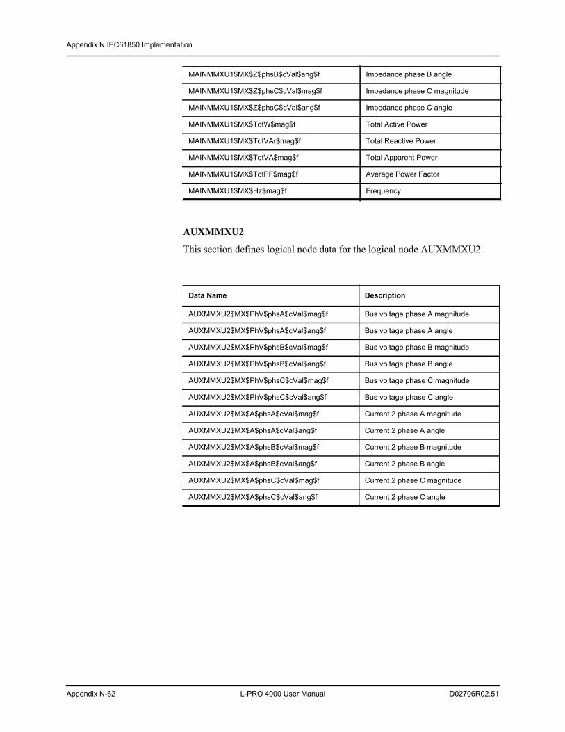
Appendix N IEC61850 Implementation
Appendix N-62 L-PRO 4000 User Manual D02706R02.51
AUXMMXU2
This section defines logical node data for the logical node AUXMMXU2.
MAINMMXU1$MX$Z$phsB$cVal$ang$f Impedance phase B angle
MAINMMXU1$MX$Z$phsC$cVal$mag$f Impedance phase C magnitude
MAINMMXU1$MX$Z$phsC$cVal$ang$f Impedance phase C angle
MAINMMXU1$MX$TotW$mag$f Total Active Power
MAINMMXU1$MX$TotVAr$mag$f Total Reactive Power
MAINMMXU1$MX$TotVA$mag$f Total Apparent Power
MAINMMXU1$MX$TotPF$mag$f Average Power Factor
MAINMMXU1$MX$Hz$mag$f Frequency
Data Name Description
AUXMMXU2$MX$PhV$phsA$cVal$mag$f Bus voltage phase A magnitude
AUXMMXU2$MX$PhV$phsA$cVal$ang$f Bus voltage phase A angle
AUXMMXU2$MX$PhV$phsB$cVal$mag$f Bus voltage phase B magnitude
AUXMMXU2$MX$PhV$phsB$cVal$ang$f Bus voltage phase B angle
AUXMMXU2$MX$PhV$phsC$cVal$mag$f Bus voltage phase C magnitude
AUXMMXU2$MX$PhV$phsC$cVal$ang$f Bus voltage phase C angle
AUXMMXU2$MX$A$phsA$cVal$mag$f Current 2 phase A magnitude
AUXMMXU2$MX$A$phsA$cVal$ang$f Current 2 phase A angle
AUXMMXU2$MX$A$phsB$cVal$mag$f Current 2 phase B magnitude
AUXMMXU2$MX$A$phsB$cVal$ang$f Current 2 phase B angle
AUXMMXU2$MX$A$phsC$cVal$mag$f Current 2 phase C magnitude
AUXMMXU2$MX$A$phsC$cVal$ang$f Current 2 phase C angle
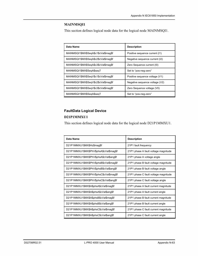
Appendix N IEC61850 Implementation
D02706R02.51 L-PRO 4000 User Manual Appendix N-63
MAINMSQI1
This section defines logical node data for the logical node MAINMSQI1.
FaultData Logical Device D21P1MMXU1
This section defines logical node data for the logical node D21P1MMXU1.
Data Name Description
MAINMSQI1$MX$SeqA$c1$cVal$mag$f Positive sequence current (I1)
MAINMSQI1$MX$SeqA$c2$cVal$mag$f Negative sequence current (I2)
MAINMSQI1$MX$SeqA$c3$cVal$mag$f Zero Sequence current (I0)
MAINMSQI1$MX$SeqA$seqT Set to “pos-neg-zero”
MAINMSQI1$MX$SeqV$c1$cVal$mag$f Positive sequence voltage (V1)
MAINMSQI1$MX$SeqV$c2$cVal$mag$f Negative sequence voltage (V2)
MAINMSQI1$MX$SeqV$c3$cVal$mag$f Zero Sequence voltage (V0)
MAINMSQI1$MX$SeqA$seqT Set to “pos-neg-zero”
Data Name Description
D21P1MMXU1$MX$Hz$mag$f 21P1 fault frequency
D21P1MMXU1$MX$PhV$phsA$cVal$mag$f 21P1 phase A fault voltage magnitude
D21P1MMXU1$MX$PhV$phsA$cVal$ang$f 21P1 phase A voltage angle
D21P1MMXU1$MX$PhV$phsB$cVal$mag$f 21P1 phase B fault voltage magnitude
D21P1MMXU1$MX$PhV$phsB$cVal$ang$f 21P1 phase B fault voltage angle
D21P1MMXU1$MX$PhV$phsC$cVal$mag$f 21P1 phase C fault voltage magnitude
D21P1MMXU1$MX$PhV$phsC$cVal$ang$f 21P1 phase C fault voltage angle
D21P1MMXU1$MX$A$phsA$cVal$mag$f 21P1 phase A fault current magnitude
D21P1MMXU1$MX$A$phsA$cVal$ang$f 21P1 phase A fault current angle
D21P1MMXU1$MX$A$phsB$cVal$mag$f 21P1 phase B fault current magnitude
D21P1MMXU1$MX$A$phsB$cVal$ang$f 21P1 phase B fault current angle
D21P1MMXU1$MX$A$phsC$cVal$mag$f 21P1 phase C fault current magnitude
D21P1MMXU1$MX$A$phsC$cVal$ang$f 21P1 phase C fault current angle
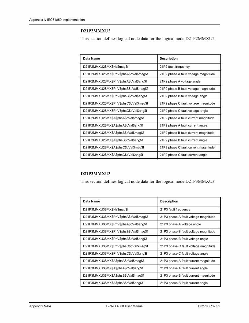
Appendix N IEC61850 Implementation
Appendix N-64 L-PRO 4000 User Manual D02706R02.51
D21P2MMXU2
This section defines logical node data for the logical node D21P2MMXU2.
D21P3MMXU3
This section defines logical node data for the logical node D21P3MMXU3.
Data Name Description
D21P2MMXU2$MX$Hz$mag$f 21P2 fault frequency
D21P2MMXU2$MX$PhV$phsA$cVal$mag$f 21P2 phase A fault voltage magnitude
D21P2MMXU2$MX$PhV$phsA$cVal$ang$f 21P2 phase A voltage angle
D21P2MMXU2$MX$PhV$phsB$cVal$mag$f 21P2 phase B fault voltage magnitude
D21P2MMXU2$MX$PhV$phsB$cVal$ang$f 21P2 phase B fault voltage angle
D21P2MMXU2$MX$PhV$phsC$cVal$mag$f 21P2 phase C fault voltage magnitude
D21P2MMXU2$MX$PhV$phsC$cVal$ang$f 21P2 phase C fault voltage angle
D21P2MMXU2$MX$A$phsA$cVal$mag$f 21P2 phase A fault current magnitude
D21P2MMXU2$MX$A$phsA$cVal$ang$f 21P2 phase A fault current angle
D21P2MMXU2$MX$A$phsB$cVal$mag$f 21P2 phase B fault current magnitude
D21P2MMXU2$MX$A$phsB$cVal$ang$f 21P2 phase B fault current angle
D21P2MMXU2$MX$A$phsC$cVal$mag$f 21P2 phase C fault current magnitude
D21P2MMXU2$MX$A$phsC$cVal$ang$f 21P2 phase C fault current angle
Data Name Description
D21P3MMXU3$MX$Hz$mag$f 21P3 fault frequency
D21P3MMXU3$MX$PhV$phsA$cVal$mag$f 21P3 phase A fault voltage magnitude
D21P3MMXU3$MX$PhV$phsA$cVal$ang$f 21P3 phase A voltage angle
D21P3MMXU3$MX$PhV$phsB$cVal$mag$f 21P3 phase B fault voltage magnitude
D21P3MMXU3$MX$PhV$phsB$cVal$ang$f 21P3 phase B fault voltage angle
D21P3MMXU3$MX$PhV$phsC$cVal$mag$f 21P3 phase C fault voltage magnitude
D21P3MMXU3$MX$PhV$phsC$cVal$ang$f 21P3 phase C fault voltage angle
D21P3MMXU3$MX$A$phsA$cVal$mag$f 21P3 phase A fault current magnitude
D21P3MMXU3$MX$A$phsA$cVal$ang$f 21P3 phase A fault current angle
D21P3MMXU3$MX$A$phsB$cVal$mag$f 21P3 phase B fault current magnitude
D21P3MMXU3$MX$A$phsB$cVal$ang$f 21P3 phase B fault current angle
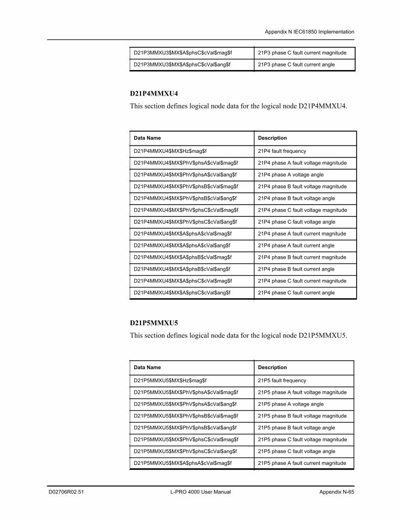
Appendix N IEC61850 Implementation
D02706R02.51 L-PRO 4000 User Manual Appendix N-65
D21P4MMXU4
This section defines logical node data for the logical node D21P4MMXU4.
D21P5MMXU5
This section defines logical node data for the logical node D21P5MMXU5.
D21P3MMXU3$MX$A$phsC$cVal$mag$f 21P3 phase C fault current magnitude
D21P3MMXU3$MX$A$phsC$cVal$ang$f 21P3 phase C fault current angle
Data Name Description
D21P4MMXU4$MX$Hz$mag$f 21P4 fault frequency
D21P4MMXU4$MX$PhV$phsA$cVal$mag$f 21P4 phase A fault voltage magnitude
D21P4MMXU4$MX$PhV$phsA$cVal$ang$f 21P4 phase A voltage angle
D21P4MMXU4$MX$PhV$phsB$cVal$mag$f 21P4 phase B fault voltage magnitude
D21P4MMXU4$MX$PhV$phsB$cVal$ang$f 21P4 phase B fault voltage angle
D21P4MMXU4$MX$PhV$phsC$cVal$mag$f 21P4 phase C fault voltage magnitude
D21P4MMXU4$MX$PhV$phsC$cVal$ang$f 21P4 phase C fault voltage angle
D21P4MMXU4$MX$A$phsA$cVal$mag$f 21P4 phase A fault current magnitude
D21P4MMXU4$MX$A$phsA$cVal$ang$f 21P4 phase A fault current angle
D21P4MMXU4$MX$A$phsB$cVal$mag$f 21P4 phase B fault current magnitude
D21P4MMXU4$MX$A$phsB$cVal$ang$f 21P4 phase B fault current angle
D21P4MMXU4$MX$A$phsC$cVal$mag$f 21P4 phase C fault current magnitude
D21P4MMXU4$MX$A$phsC$cVal$ang$f 21P4 phase C fault current angle
Data Name Description
D21P5MMXU5$MX$Hz$mag$f 21P5 fault frequency
D21P5MMXU5$MX$PhV$phsA$cVal$mag$f 21P5 phase A fault voltage magnitude
D21P5MMXU5$MX$PhV$phsA$cVal$ang$f 21P5 phase A voltage angle
D21P5MMXU5$MX$PhV$phsB$cVal$mag$f 21P5 phase B fault voltage magnitude
D21P5MMXU5$MX$PhV$phsB$cVal$ang$f 21P5 phase B fault voltage angle
D21P5MMXU5$MX$PhV$phsC$cVal$mag$f 21P5 phase C fault voltage magnitude
D21P5MMXU5$MX$PhV$phsC$cVal$ang$f 21P5 phase C fault voltage angle
D21P5MMXU5$MX$A$phsA$cVal$mag$f 21P5 phase A fault current magnitude
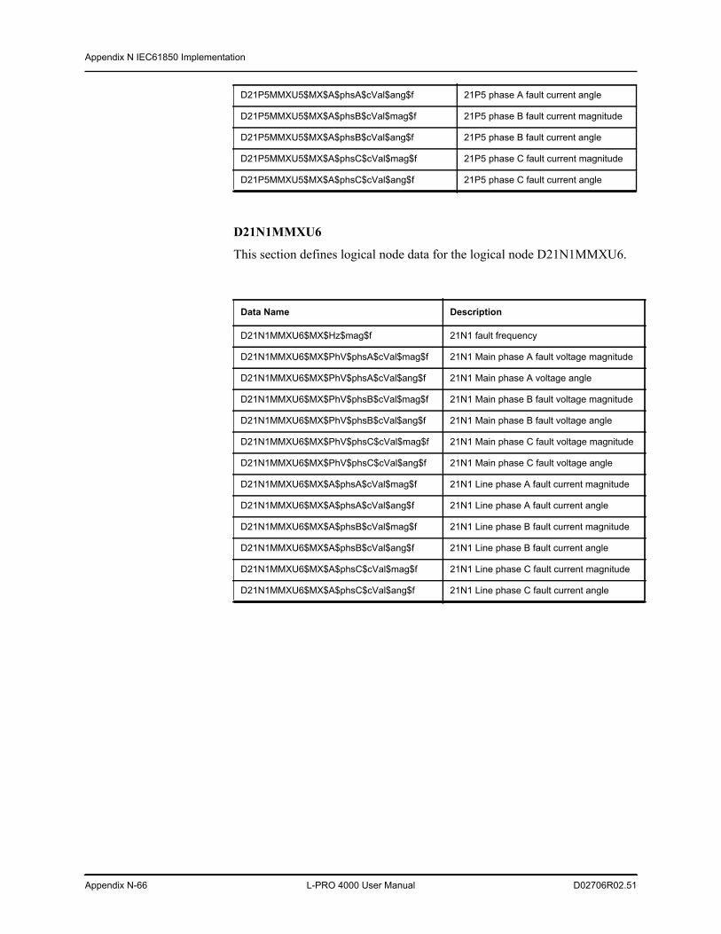
Appendix N IEC61850 Implementation
Appendix N-66 L-PRO 4000 User Manual D02706R02.51
D21N1MMXU6
This section defines logical node data for the logical node D21N1MMXU6.
D21P5MMXU5$MX$A$phsA$cVal$ang$f 21P5 phase A fault current angle
D21P5MMXU5$MX$A$phsB$cVal$mag$f 21P5 phase B fault current magnitude
D21P5MMXU5$MX$A$phsB$cVal$ang$f 21P5 phase B fault current angle
D21P5MMXU5$MX$A$phsC$cVal$mag$f 21P5 phase C fault current magnitude
D21P5MMXU5$MX$A$phsC$cVal$ang$f 21P5 phase C fault current angle
Data Name Description
D21N1MMXU6$MX$Hz$mag$f 21N1 fault frequency
D21N1MMXU6$MX$PhV$phsA$cVal$mag$f 21N1 Main phase A fault voltage magnitude
D21N1MMXU6$MX$PhV$phsA$cVal$ang$f 21N1 Main phase A voltage angle
D21N1MMXU6$MX$PhV$phsB$cVal$mag$f 21N1 Main phase B fault voltage magnitude
D21N1MMXU6$MX$PhV$phsB$cVal$ang$f 21N1 Main phase B fault voltage angle
D21N1MMXU6$MX$PhV$phsC$cVal$mag$f 21N1 Main phase C fault voltage magnitude
D21N1MMXU6$MX$PhV$phsC$cVal$ang$f 21N1 Main phase C fault voltage angle
D21N1MMXU6$MX$A$phsA$cVal$mag$f 21N1 Line phase A fault current magnitude
D21N1MMXU6$MX$A$phsA$cVal$ang$f 21N1 Line phase A fault current angle
D21N1MMXU6$MX$A$phsB$cVal$mag$f 21N1 Line phase B fault current magnitude
D21N1MMXU6$MX$A$phsB$cVal$ang$f 21N1 Line phase B fault current angle
D21N1MMXU6$MX$A$phsC$cVal$mag$f 21N1 Line phase C fault current magnitude
D21N1MMXU6$MX$A$phsC$cVal$ang$f 21N1 Line phase C fault current angle
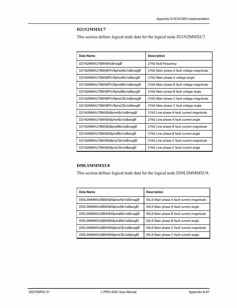
Appendix N IEC61850 Implementation
D02706R02.51 L-PRO 4000 User Manual Appendix N-67
D21N2MMXU7
This section defines logical node data for the logical node D21N2MMXU7.
D50LSMMMXU8
This section defines logical node data for the logical node D50LSMMMXU8.
Data Name Description
D21N2MMXU7$MX$Hz$mag$f 21N2 fault frequency
D21N2MMXU7$MX$PhV$phsA$cVal$mag$f 21N2 Main phase A fault voltage magnitude
D21N2MMXU7$MX$PhV$phsA$cVal$ang$f 21N2 Main phase A voltage angle
D21N2MMXU7$MX$PhV$phsB$cVal$mag$f 21N2 Main phase B fault voltage magnitude
D21N2MMXU7$MX$PhV$phsB$cVal$ang$f 21N2 Main phase B fault voltage angle
D21N2MMXU7$MX$PhV$phsC$cVal$mag$f 21N2 Main phase C fault voltage magnitude
D21N2MMXU7$MX$PhV$phsC$cVal$ang$f 21N2 Main phase C fault voltage angle
D21N2MMXU7$MX$A$phsA$cVal$mag$f 21N2 Line phase A fault current magnitude
D21N2MMXU7$MX$A$phsA$cVal$ang$f 21N2 Line phase A fault current angle
D21N2MMXU7$MX$A$phsB$cVal$mag$f 21N2 Line phase B fault current magnitude
D21N2MMXU7$MX$A$phsB$cVal$ang$f 21N2 Line phase B fault current angle
D21N2MMXU7$MX$A$phsC$cVal$mag$f 21N2 Line phase C fault current magnitude
D21N2MMXU7$MX$A$phsC$cVal$ang$f 21N2 Line phase C fault current angle
Data Name Description
D50LSMMMXU8$MX$A$phsA$cVal$mag$f 50LS Main phase A fault current magnitude
D50LSMMMXU8$MX$A$phsA$cVal$ang$f 50LS Main phase A fault current angle
D50LSMMMXU8$MX$A$phsB$cVal$mag$f 50LS Main phase B fault current magnitude
D50LSMMMXU8$MX$A$phsB$cVal$ang$f 50LS Main phase B fault current angle
D50LSMMMXU8$MX$A$phsC$cVal$mag$f 50LS Main phase C fault current magnitude
D50LSMMMXU8$MX$A$phsC$cVal$ang$f 50LS Main phase C fault current angle
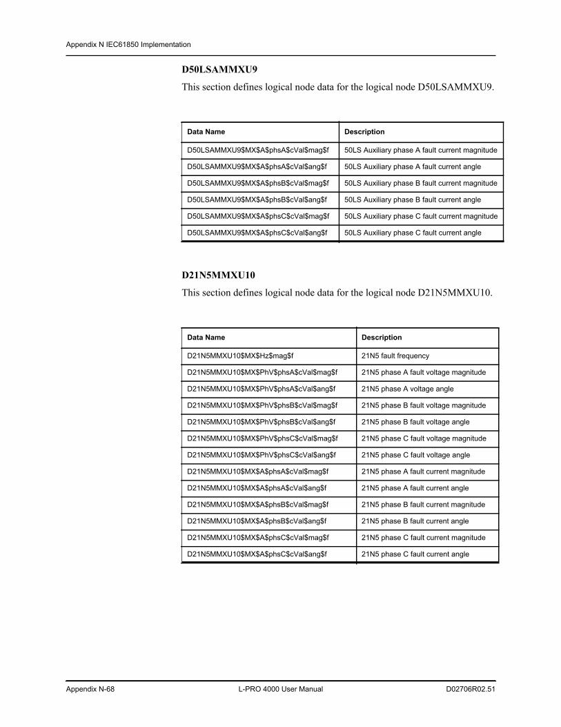
Appendix N IEC61850 Implementation
Appendix N-68 L-PRO 4000 User Manual D02706R02.51
D50LSAMMXU9
This section defines logical node data for the logical node D50LSAMMXU9.
D21N5MMXU10
This section defines logical node data for the logical node D21N5MMXU10.
Data Name Description
D50LSAMMXU9$MX$A$phsA$cVal$mag$f 50LS Auxiliary phase A fault current magnitude
D50LSAMMXU9$MX$A$phsA$cVal$ang$f 50LS Auxiliary phase A fault current angle
D50LSAMMXU9$MX$A$phsB$cVal$mag$f 50LS Auxiliary phase B fault current magnitude
D50LSAMMXU9$MX$A$phsB$cVal$ang$f 50LS Auxiliary phase B fault current angle
D50LSAMMXU9$MX$A$phsC$cVal$mag$f 50LS Auxiliary phase C fault current magnitude
D50LSAMMXU9$MX$A$phsC$cVal$ang$f 50LS Auxiliary phase C fault current angle
Data Name Description
D21N5MMXU10$MX$Hz$mag$f 21N5 fault frequency
D21N5MMXU10$MX$PhV$phsA$cVal$mag$f 21N5 phase A fault voltage magnitude
D21N5MMXU10$MX$PhV$phsA$cVal$ang$f 21N5 phase A voltage angle
D21N5MMXU10$MX$PhV$phsB$cVal$mag$f 21N5 phase B fault voltage magnitude
D21N5MMXU10$MX$PhV$phsB$cVal$ang$f 21N5 phase B fault voltage angle
D21N5MMXU10$MX$PhV$phsC$cVal$mag$f 21N5 phase C fault voltage magnitude
D21N5MMXU10$MX$PhV$phsC$cVal$ang$f 21N5 phase C fault voltage angle
D21N5MMXU10$MX$A$phsA$cVal$mag$f 21N5 phase A fault current magnitude
D21N5MMXU10$MX$A$phsA$cVal$ang$f 21N5 phase A fault current angle
D21N5MMXU10$MX$A$phsB$cVal$mag$f 21N5 phase B fault current magnitude
D21N5MMXU10$MX$A$phsB$cVal$ang$f 21N5 phase B fault current angle
D21N5MMXU10$MX$A$phsC$cVal$mag$f 21N5 phase C fault current magnitude
D21N5MMXU10$MX$A$phsC$cVal$ang$f 21N5 phase C fault current angle
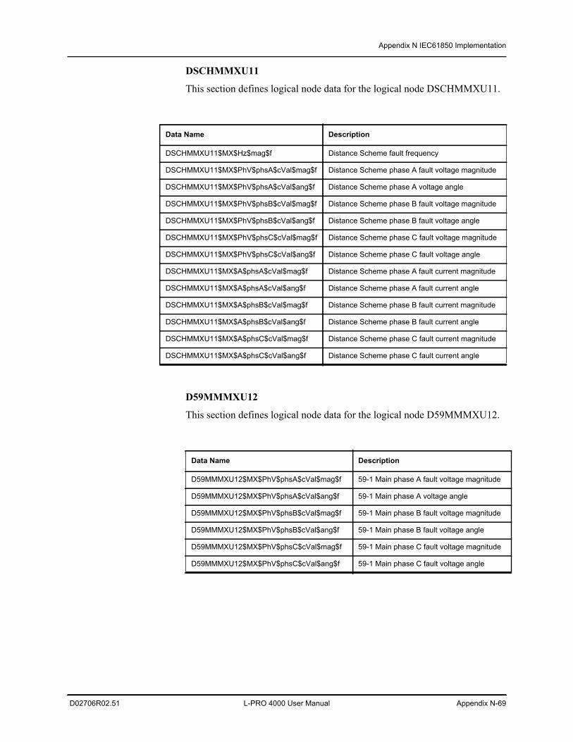
Appendix N IEC61850 Implementation
D02706R02.51 L-PRO 4000 User Manual Appendix N-69
DSCHMMXU11
This section defines logical node data for the logical node DSCHMMXU11.
D59MMMXU12
This section defines logical node data for the logical node D59MMMXU12.
Data Name Description
DSCHMMXU11$MX$Hz$mag$f Distance Scheme fault frequency
DSCHMMXU11$MX$PhV$phsA$cVal$mag$f Distance Scheme phase A fault voltage magnitude
DSCHMMXU11$MX$PhV$phsA$cVal$ang$f Distance Scheme phase A voltage angle
DSCHMMXU11$MX$PhV$phsB$cVal$mag$f Distance Scheme phase B fault voltage magnitude
DSCHMMXU11$MX$PhV$phsB$cVal$ang$f Distance Scheme phase B fault voltage angle
DSCHMMXU11$MX$PhV$phsC$cVal$mag$f Distance Scheme phase C fault voltage magnitude
DSCHMMXU11$MX$PhV$phsC$cVal$ang$f Distance Scheme phase C fault voltage angle
DSCHMMXU11$MX$A$phsA$cVal$mag$f Distance Scheme phase A fault current magnitude
DSCHMMXU11$MX$A$phsA$cVal$ang$f Distance Scheme phase A fault current angle
DSCHMMXU11$MX$A$phsB$cVal$mag$f Distance Scheme phase B fault current magnitude
DSCHMMXU11$MX$A$phsB$cVal$ang$f Distance Scheme phase B fault current angle
DSCHMMXU11$MX$A$phsC$cVal$mag$f Distance Scheme phase C fault current magnitude
DSCHMMXU11$MX$A$phsC$cVal$ang$f Distance Scheme phase C fault current angle
Data Name Description
D59MMMXU12$MX$PhV$phsA$cVal$mag$f 59-1 Main phase A fault voltage magnitude
D59MMMXU12$MX$PhV$phsA$cVal$ang$f 59-1 Main phase A voltage angle
D59MMMXU12$MX$PhV$phsB$cVal$mag$f 59-1 Main phase B fault voltage magnitude
D59MMMXU12$MX$PhV$phsB$cVal$ang$f 59-1 Main phase B fault voltage angle
D59MMMXU12$MX$PhV$phsC$cVal$mag$f 59-1 Main phase C fault voltage magnitude
D59MMMXU12$MX$PhV$phsC$cVal$ang$f 59-1 Main phase C fault voltage angle
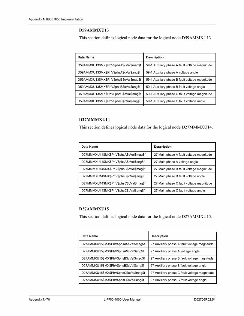
Appendix N IEC61850 Implementation
Appendix N-70 L-PRO 4000 User Manual D02706R02.51
D59AMMXU13
This section defines logical node data for the logical node D59AMMXU13.
D27MMMXU14
This section defines logical node data for the logical node D27MMMXU14.
D27AMMXU15
This section defines logical node data for the logical node D27AMMXU15.
Data Name Description
D59AMMXU13$MX$PhV$phsA$cVal$mag$f 59-1 Auxiliary phase A fault voltage magnitude
D59AMMXU13$MX$PhV$phsA$cVal$ang$f 59-1 Auxiliary phase A voltage angle
D59AMMXU13$MX$PhV$phsB$cVal$mag$f 59-1 Auxiliary phase B fault voltage magnitude
D59AMMXU13$MX$PhV$phsB$cVal$ang$f 59-1 Auxiliary phase B fault voltage angle
D59AMMXU13$MX$PhV$phsC$cVal$mag$f 59-1 Auxiliary phase C fault voltage magnitude
D59AMMXU13$MX$PhV$phsC$cVal$ang$f 59-1 Auxiliary phase C fault voltage angle
Data Name Description
D27MMMXU14$MX$PhV$phsA$cVal$mag$f 27 Main phase A fault voltage magnitude
D27MMMXU14$MX$PhV$phsA$cVal$ang$f 27 Main phase A voltage angle
D27MMMXU14$MX$PhV$phsB$cVal$mag$f 27 Main phase B fault voltage magnitude
D27MMMXU14$MX$PhV$phsB$cVal$ang$f 27 Main phase B fault voltage angle
D27MMMXU14$MX$PhV$phsC$cVal$mag$f 27 Main phase C fault voltage magnitude
D27MMMXU14$MX$PhV$phsC$cVal$ang$f 27 Main phase C fault voltage angle
Data Name Description
D27AMMXU15$MX$PhV$phsA$cVal$mag$f 27 Auxiliary phase A fault voltage magnitude
D27AMMXU15$MX$PhV$phsA$cVal$ang$f 27 Auxiliary phase A voltage angle
D27AMMXU15$MX$PhV$phsB$cVal$mag$f 27 Auxiliary phase B fault voltage magnitude
D27AMMXU15$MX$PhV$phsB$cVal$ang$f 27 Auxiliary phase B fault voltage angle
D27AMMXU15$MX$PhV$phsC$cVal$mag$f 27 Auxiliary phase C fault voltage magnitude
D27AMMXU15$MX$PhV$phsC$cVal$ang$f 27 Auxiliary phase C fault voltage angle
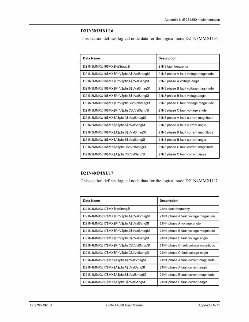
Appendix N IEC61850 Implementation
D02706R02.51 L-PRO 4000 User Manual Appendix N-71
D21N3MMXU16
This section defines logical node data for the logical node D21N3MMXU16.
D21N4MMXU17
This section defines logical node data for the logical node D21N4MMXU17.
Data Name Description
D21N3MMXU16$MX$Hz$mag$f 21N3 fault frequency
D21N3MMXU16$MX$PhV$phsA$cVal$mag$f 21N3 phase A fault voltage magnitude
D21N3MMXU16$MX$PhV$phsA$cVal$ang$f 21N3 phase A voltage angle
D21N3MMXU16$MX$PhV$phsB$cVal$mag$f 21N3 phase B fault voltage magnitude
D21N3MMXU16$MX$PhV$phsB$cVal$ang$f 21N3 phase B fault voltage angle
D21N3MMXU16$MX$PhV$phsC$cVal$mag$f 21N3 phase C fault voltage magnitude
D21N3MMXU16$MX$PhV$phsC$cVal$ang$f 21N3 phase C fault voltage angle
D21N3MMXU16$MX$A$phsA$cVal$mag$f 21N3 phase A fault current magnitude
D21N3MMXU16$MX$A$phsA$cVal$ang$f 21N3 phase A fault current angle
D21N3MMXU16$MX$A$phsB$cVal$mag$f 21N3 phase B fault current magnitude
D21N3MMXU16$MX$A$phsB$cVal$ang$f 21N3 phase B fault current angle
D21N3MMXU16$MX$A$phsC$cVal$mag$f 21N3 phase C fault current magnitude
D21N3MMXU16$MX$A$phsC$cVal$ang$f 21N3 phase C fault current angle
Data Name Description
D21N4MMXU17$MX$Hz$mag$f 21N4 fault frequency
D21N4MMXU17$MX$PhV$phsA$cVal$mag$f 21N4 phase A fault voltage magnitude
D21N4MMXU17$MX$PhV$phsA$cVal$ang$f 21N4 phase A voltage angle
D21N4MMXU17$MX$PhV$phsB$cVal$mag$f 21N4 phase B fault voltage magnitude
D21N4MMXU17$MX$PhV$phsB$cVal$ang$f 21N4 phase B fault voltage angle
D21N4MMXU17$MX$PhV$phsC$cVal$mag$f 21N4 phase C fault voltage magnitude
D21N4MMXU17$MX$PhV$phsC$cVal$ang$f 21N4 phase C fault voltage angle
D21N4MMXU17$MX$A$phsA$cVal$mag$f 21N4 phase A fault current magnitude
D21N4MMXU17$MX$A$phsA$cVal$ang$f 21N4 phase A fault current angle
D21N4MMXU17$MX$A$phsB$cVal$mag$f 21N4 phase B fault current magnitude
D21N4MMXU17$MX$A$phsB$cVal$ang$f 21N4 phase B fault current angle
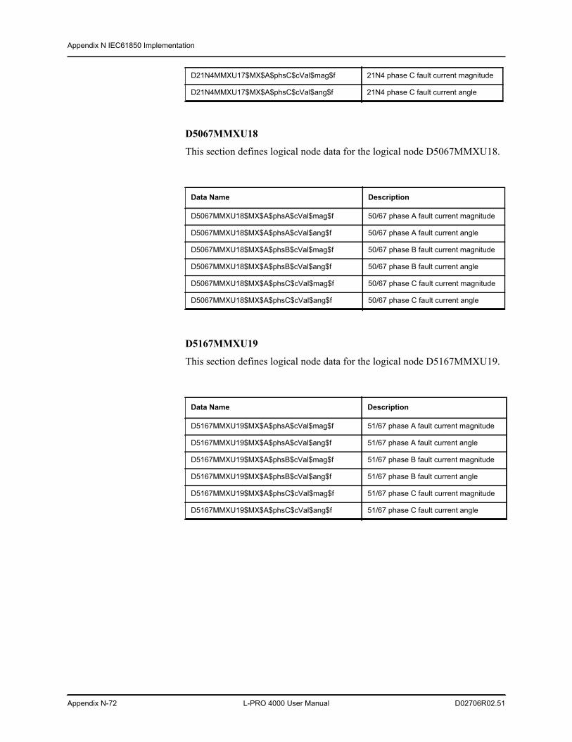
Appendix N IEC61850 Implementation
Appendix N-72 L-PRO 4000 User Manual D02706R02.51
D5067MMXU18
This section defines logical node data for the logical node D5067MMXU18.
D5167MMXU19
This section defines logical node data for the logical node D5167MMXU19.
D21N4MMXU17$MX$A$phsC$cVal$mag$f 21N4 phase C fault current magnitude
D21N4MMXU17$MX$A$phsC$cVal$ang$f 21N4 phase C fault current angle
Data Name Description
D5067MMXU18$MX$A$phsA$cVal$mag$f 50/67 phase A fault current magnitude
D5067MMXU18$MX$A$phsA$cVal$ang$f 50/67 phase A fault current angle
D5067MMXU18$MX$A$phsB$cVal$mag$f 50/67 phase B fault current magnitude
D5067MMXU18$MX$A$phsB$cVal$ang$f 50/67 phase B fault current angle
D5067MMXU18$MX$A$phsC$cVal$mag$f 50/67 phase C fault current magnitude
D5067MMXU18$MX$A$phsC$cVal$ang$f 50/67 phase C fault current angle
Data Name Description
D5167MMXU19$MX$A$phsA$cVal$mag$f 51/67 phase A fault current magnitude
D5167MMXU19$MX$A$phsA$cVal$ang$f 51/67 phase A fault current angle
D5167MMXU19$MX$A$phsB$cVal$mag$f 51/67 phase B fault current magnitude
D5167MMXU19$MX$A$phsB$cVal$ang$f 51/67 phase B fault current angle
D5167MMXU19$MX$A$phsC$cVal$mag$f 51/67 phase C fault current magnitude
D5167MMXU19$MX$A$phsC$cVal$ang$f 51/67 phase C fault current angle
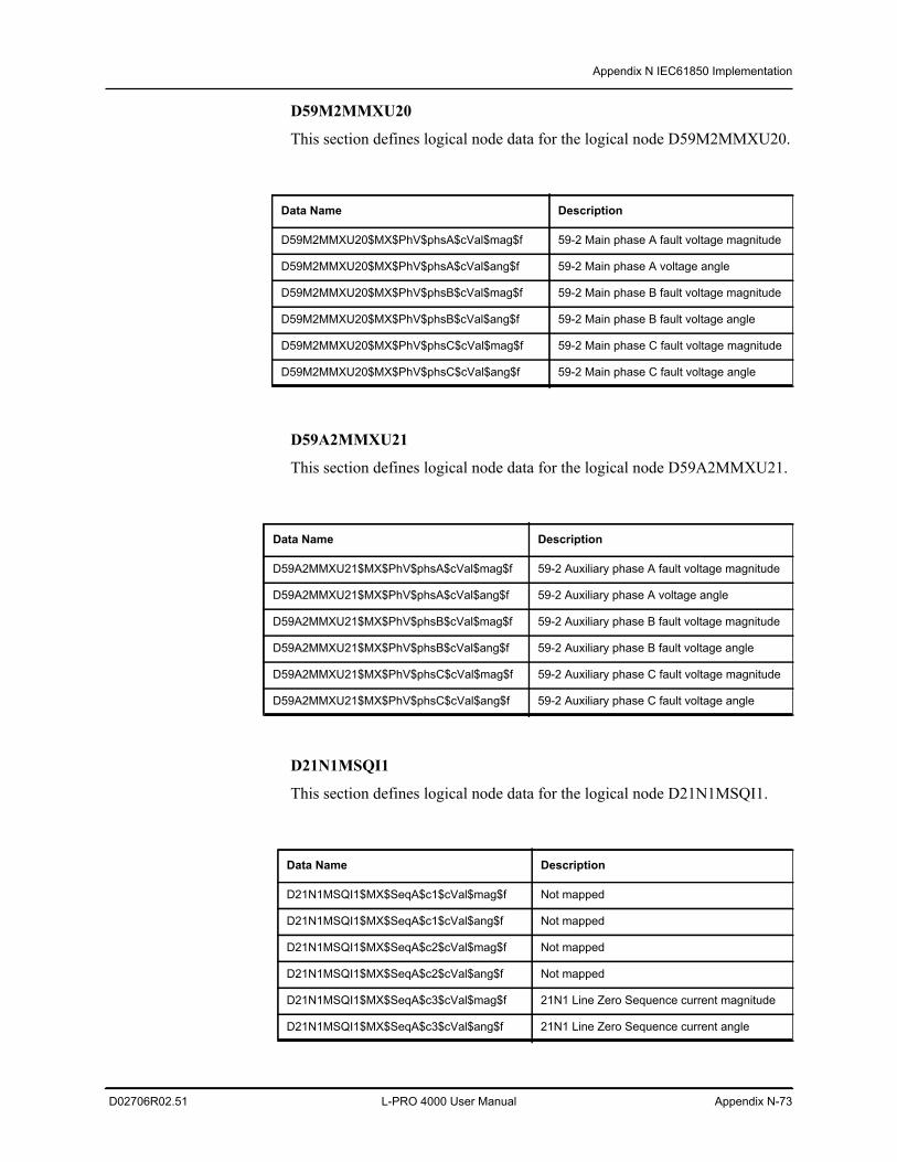
Appendix N IEC61850 Implementation
D02706R02.51 L-PRO 4000 User Manual Appendix N-73
D59M2MMXU20
This section defines logical node data for the logical node D59M2MMXU20.
D59A2MMXU21
This section defines logical node data for the logical node D59A2MMXU21.
D21N1MSQI1
This section defines logical node data for the logical node D21N1MSQI1.
Data Name Description
D59M2MMXU20$MX$PhV$phsA$cVal$mag$f 59-2 Main phase A fault voltage magnitude
D59M2MMXU20$MX$PhV$phsA$cVal$ang$f 59-2 Main phase A voltage angle
D59M2MMXU20$MX$PhV$phsB$cVal$mag$f 59-2 Main phase B fault voltage magnitude
D59M2MMXU20$MX$PhV$phsB$cVal$ang$f 59-2 Main phase B fault voltage angle
D59M2MMXU20$MX$PhV$phsC$cVal$mag$f 59-2 Main phase C fault voltage magnitude
D59M2MMXU20$MX$PhV$phsC$cVal$ang$f 59-2 Main phase C fault voltage angle
Data Name Description
D59A2MMXU21$MX$PhV$phsA$cVal$mag$f 59-2 Auxiliary phase A fault voltage magnitude
D59A2MMXU21$MX$PhV$phsA$cVal$ang$f 59-2 Auxiliary phase A voltage angle
D59A2MMXU21$MX$PhV$phsB$cVal$mag$f 59-2 Auxiliary phase B fault voltage magnitude
D59A2MMXU21$MX$PhV$phsB$cVal$ang$f 59-2 Auxiliary phase B fault voltage angle
D59A2MMXU21$MX$PhV$phsC$cVal$mag$f 59-2 Auxiliary phase C fault voltage magnitude
D59A2MMXU21$MX$PhV$phsC$cVal$ang$f 59-2 Auxiliary phase C fault voltage angle
Data Name Description
D21N1MSQI1$MX$SeqA$c1$cVal$mag$f Not mapped
D21N1MSQI1$MX$SeqA$c1$cVal$ang$f Not mapped
D21N1MSQI1$MX$SeqA$c2$cVal$mag$f Not mapped
D21N1MSQI1$MX$SeqA$c2$cVal$ang$f Not mapped
D21N1MSQI1$MX$SeqA$c3$cVal$mag$f 21N1 Line Zero Sequence current magnitude
D21N1MSQI1$MX$SeqA$c3$cVal$ang$f 21N1 Line Zero Sequence current angle
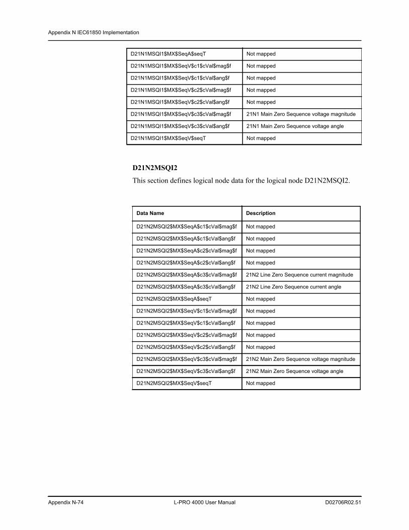
Appendix N IEC61850 Implementation
Appendix N-74 L-PRO 4000 User Manual D02706R02.51
D21N2MSQI2
This section defines logical node data for the logical node D21N2MSQI2.
D21N1MSQI1$MX$SeqA$seqT Not mapped
D21N1MSQI1$MX$SeqV$c1$cVal$mag$f Not mapped
D21N1MSQI1$MX$SeqV$c1$cVal$ang$f Not mapped
D21N1MSQI1$MX$SeqV$c2$cVal$mag$f Not mapped
D21N1MSQI1$MX$SeqV$c2$cVal$ang$f Not mapped
D21N1MSQI1$MX$SeqV$c3$cVal$mag$f 21N1 Main Zero Sequence voltage magnitude
D21N1MSQI1$MX$SeqV$c3$cVal$ang$f 21N1 Main Zero Sequence voltage angle
D21N1MSQI1$MX$SeqV$seqT Not mapped
Data Name Description
D21N2MSQI2$MX$SeqA$c1$cVal$mag$f Not mapped
D21N2MSQI2$MX$SeqA$c1$cVal$ang$f Not mapped
D21N2MSQI2$MX$SeqA$c2$cVal$mag$f Not mapped
D21N2MSQI2$MX$SeqA$c2$cVal$ang$f Not mapped
D21N2MSQI2$MX$SeqA$c3$cVal$mag$f 21N2 Line Zero Sequence current magnitude
D21N2MSQI2$MX$SeqA$c3$cVal$ang$f 21N2 Line Zero Sequence current angle
D21N2MSQI2$MX$SeqA$seqT Not mapped
D21N2MSQI2$MX$SeqV$c1$cVal$mag$f Not mapped
D21N2MSQI2$MX$SeqV$c1$cVal$ang$f Not mapped
D21N2MSQI2$MX$SeqV$c2$cVal$mag$f Not mapped
D21N2MSQI2$MX$SeqV$c2$cVal$ang$f Not mapped
D21N2MSQI2$MX$SeqV$c3$cVal$mag$f 21N2 Main Zero Sequence voltage magnitude
D21N2MSQI2$MX$SeqV$c3$cVal$ang$f 21N2 Main Zero Sequence voltage angle
D21N2MSQI2$MX$SeqV$seqT Not mapped
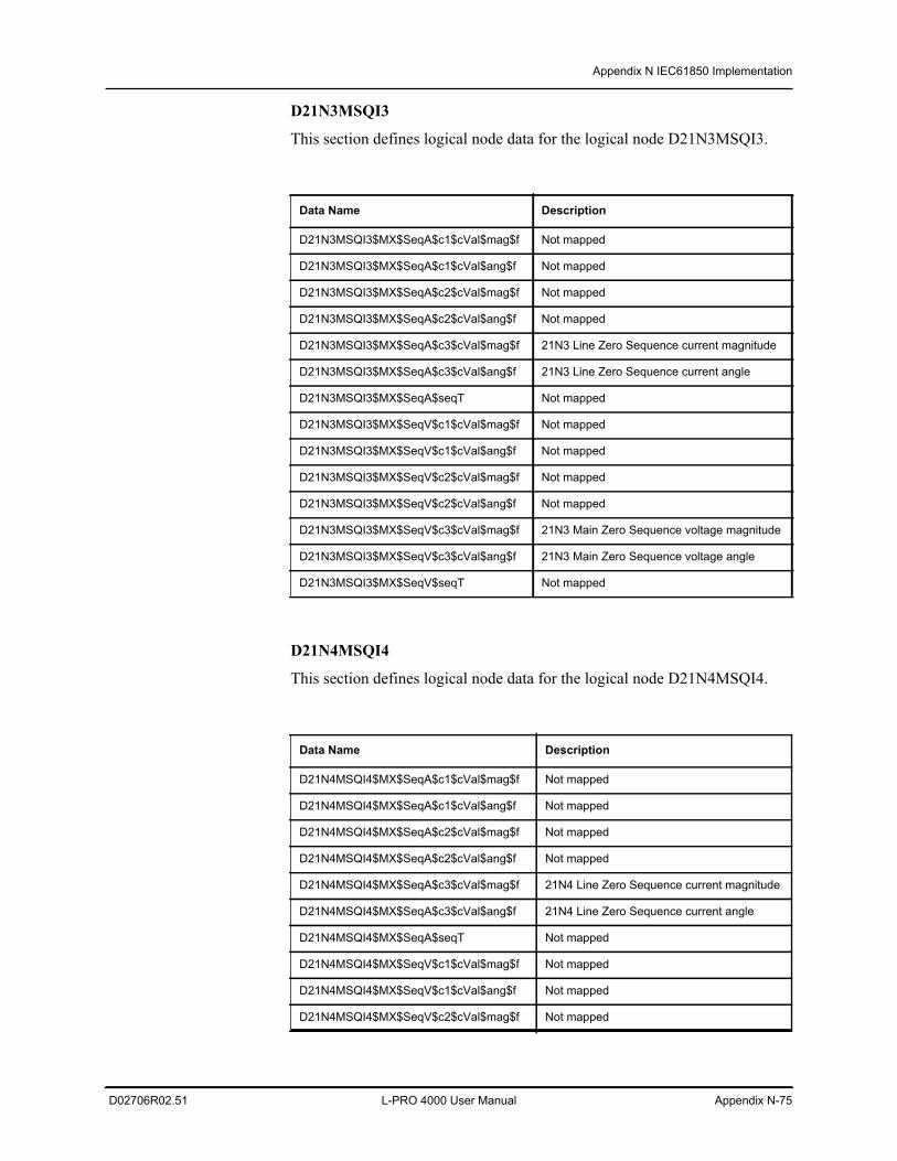
Appendix N IEC61850 Implementation
D02706R02.51 L-PRO 4000 User Manual Appendix N-75
D21N3MSQI3
This section defines logical node data for the logical node D21N3MSQI3.
D21N4MSQI4
This section defines logical node data for the logical node D21N4MSQI4.
Data Name Description
D21N3MSQI3$MX$SeqA$c1$cVal$mag$f Not mapped
D21N3MSQI3$MX$SeqA$c1$cVal$ang$f Not mapped
D21N3MSQI3$MX$SeqA$c2$cVal$mag$f Not mapped
D21N3MSQI3$MX$SeqA$c2$cVal$ang$f Not mapped
D21N3MSQI3$MX$SeqA$c3$cVal$mag$f 21N3 Line Zero Sequence current magnitude
D21N3MSQI3$MX$SeqA$c3$cVal$ang$f 21N3 Line Zero Sequence current angle
D21N3MSQI3$MX$SeqA$seqT Not mapped
D21N3MSQI3$MX$SeqV$c1$cVal$mag$f Not mapped
D21N3MSQI3$MX$SeqV$c1$cVal$ang$f Not mapped
D21N3MSQI3$MX$SeqV$c2$cVal$mag$f Not mapped
D21N3MSQI3$MX$SeqV$c2$cVal$ang$f Not mapped
D21N3MSQI3$MX$SeqV$c3$cVal$mag$f 21N3 Main Zero Sequence voltage magnitude
D21N3MSQI3$MX$SeqV$c3$cVal$ang$f 21N3 Main Zero Sequence voltage angle
D21N3MSQI3$MX$SeqV$seqT Not mapped
Data Name Description
D21N4MSQI4$MX$SeqA$c1$cVal$mag$f Not mapped
D21N4MSQI4$MX$SeqA$c1$cVal$ang$f Not mapped
D21N4MSQI4$MX$SeqA$c2$cVal$mag$f Not mapped
D21N4MSQI4$MX$SeqA$c2$cVal$ang$f Not mapped
D21N4MSQI4$MX$SeqA$c3$cVal$mag$f 21N4 Line Zero Sequence current magnitude
D21N4MSQI4$MX$SeqA$c3$cVal$ang$f 21N4 Line Zero Sequence current angle
D21N4MSQI4$MX$SeqA$seqT Not mapped
D21N4MSQI4$MX$SeqV$c1$cVal$mag$f Not mapped
D21N4MSQI4$MX$SeqV$c1$cVal$ang$f Not mapped
D21N4MSQI4$MX$SeqV$c2$cVal$mag$f Not mapped
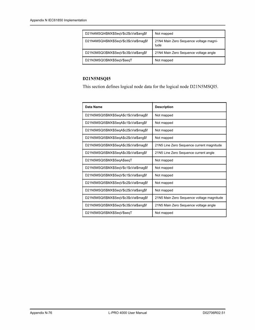
Appendix N IEC61850 Implementation
Appendix N-76 L-PRO 4000 User Manual D02706R02.51
D21N5MSQI5
This section defines logical node data for the logical node D21N5MSQI5.
D21N4MSQI4$MX$SeqV$c2$cVal$ang$f Not mapped
D21N4MSQI4$MX$SeqV$c3$cVal$mag$f 21N4 Main Zero Sequence voltage magni-tude
D21N3MSQI3$MX$SeqV$c3$cVal$ang$f 21N4 Main Zero Sequence voltage angle
D21N3MSQI3$MX$SeqV$seqT Not mapped
Data Name Description
D21N5MSQI5$MX$SeqA$c1$cVal$mag$f Not mapped
D21N5MSQI5$MX$SeqA$c1$cVal$ang$f Not mapped
D21N5MSQI5$MX$SeqA$c2$cVal$mag$f Not mapped
D21N5MSQI5$MX$SeqA$c2$cVal$ang$f Not mapped
D21N5MSQI5$MX$SeqA$c3$cVal$mag$f 21N5 Line Zero Sequence current magnitude
D21N5MSQI5$MX$SeqA$c3$cVal$ang$f 21N5 Line Zero Sequence current angle
D21N5MSQI5$MX$SeqA$seqT Not mapped
D21N5MSQI5$MX$SeqV$c1$cVal$mag$f Not mapped
D21N5MSQI5$MX$SeqV$c1$cVal$ang$f Not mapped
D21N5MSQI5$MX$SeqV$c2$cVal$mag$f Not mapped
D21N5MSQI5$MX$SeqV$c2$cVal$ang$f Not mapped
D21N5MSQI5$MX$SeqV$c3$cVal$mag$f 21N5 Main Zero Sequence voltage magnitude
D21N5MSQI5$MX$SeqV$c3$cVal$ang$f 21N5 Main Zero Sequence voltage angle
D21N5MSQI5$MX$SeqV$seqT Not mapped
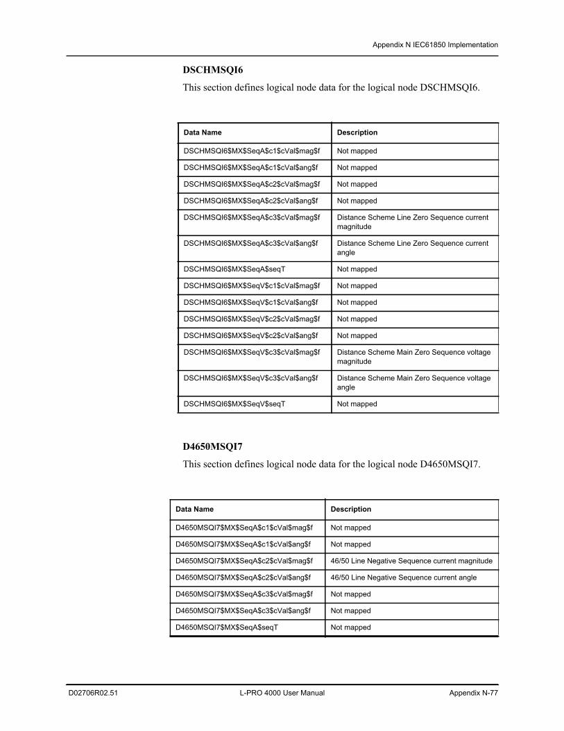
Appendix N IEC61850 Implementation
D02706R02.51 L-PRO 4000 User Manual Appendix N-77
DSCHMSQI6
This section defines logical node data for the logical node DSCHMSQI6.
D4650MSQI7
This section defines logical node data for the logical node D4650MSQI7.
Data Name Description
DSCHMSQI6$MX$SeqA$c1$cVal$mag$f Not mapped
DSCHMSQI6$MX$SeqA$c1$cVal$ang$f Not mapped
DSCHMSQI6$MX$SeqA$c2$cVal$mag$f Not mapped
DSCHMSQI6$MX$SeqA$c2$cVal$ang$f Not mapped
DSCHMSQI6$MX$SeqA$c3$cVal$mag$f Distance Scheme Line Zero Sequence current magnitude
DSCHMSQI6$MX$SeqA$c3$cVal$ang$f Distance Scheme Line Zero Sequence current angle
DSCHMSQI6$MX$SeqA$seqT Not mapped
DSCHMSQI6$MX$SeqV$c1$cVal$mag$f Not mapped
DSCHMSQI6$MX$SeqV$c1$cVal$ang$f Not mapped
DSCHMSQI6$MX$SeqV$c2$cVal$mag$f Not mapped
DSCHMSQI6$MX$SeqV$c2$cVal$ang$f Not mapped
DSCHMSQI6$MX$SeqV$c3$cVal$mag$f Distance Scheme Main Zero Sequence voltage magnitude
DSCHMSQI6$MX$SeqV$c3$cVal$ang$f Distance Scheme Main Zero Sequence voltage angle
DSCHMSQI6$MX$SeqV$seqT Not mapped
Data Name Description
D4650MSQI7$MX$SeqA$c1$cVal$mag$f Not mapped
D4650MSQI7$MX$SeqA$c1$cVal$ang$f Not mapped
D4650MSQI7$MX$SeqA$c2$cVal$mag$f 46/50 Line Negative Sequence current magnitude
D4650MSQI7$MX$SeqA$c2$cVal$ang$f 46/50 Line Negative Sequence current angle
D4650MSQI7$MX$SeqA$c3$cVal$mag$f Not mapped
D4650MSQI7$MX$SeqA$c3$cVal$ang$f Not mapped
D4650MSQI7$MX$SeqA$seqT Not mapped
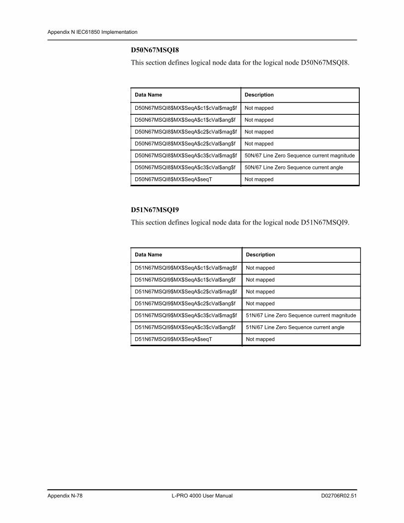
Appendix N IEC61850 Implementation
Appendix N-78 L-PRO 4000 User Manual D02706R02.51
D50N67MSQI8
This section defines logical node data for the logical node D50N67MSQI8.
D51N67MSQI9
This section defines logical node data for the logical node D51N67MSQI9.
Data Name Description
D50N67MSQI8$MX$SeqA$c1$cVal$mag$f Not mapped
D50N67MSQI8$MX$SeqA$c1$cVal$ang$f Not mapped
D50N67MSQI8$MX$SeqA$c2$cVal$mag$f Not mapped
D50N67MSQI8$MX$SeqA$c2$cVal$ang$f Not mapped
D50N67MSQI8$MX$SeqA$c3$cVal$mag$f 50N/67 Line Zero Sequence current magnitude
D50N67MSQI8$MX$SeqA$c3$cVal$ang$f 50N/67 Line Zero Sequence current angle
D50N67MSQI8$MX$SeqA$seqT Not mapped
Data Name Description
D51N67MSQI9$MX$SeqA$c1$cVal$mag$f Not mapped
D51N67MSQI9$MX$SeqA$c1$cVal$ang$f Not mapped
D51N67MSQI9$MX$SeqA$c2$cVal$mag$f Not mapped
D51N67MSQI9$MX$SeqA$c2$cVal$ang$f Not mapped
D51N67MSQI9$MX$SeqA$c3$cVal$mag$f 51N/67 Line Zero Sequence current magnitude
D51N67MSQI9$MX$SeqA$c3$cVal$ang$f 51N/67 Line Zero Sequence current angle
D51N67MSQI9$MX$SeqA$seqT Not mapped
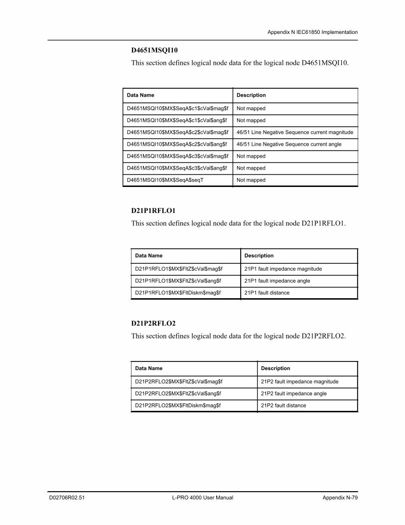
Appendix N IEC61850 Implementation
D02706R02.51 L-PRO 4000 User Manual Appendix N-79
D4651MSQI10
This section defines logical node data for the logical node D4651MSQI10.
D21P1RFLO1
This section defines logical node data for the logical node D21P1RFLO1.
D21P2RFLO2
This section defines logical node data for the logical node D21P2RFLO2.
Data Name Description
D4651MSQI10$MX$SeqA$c1$cVal$mag$f Not mapped
D4651MSQI10$MX$SeqA$c1$cVal$ang$f Not mapped
D4651MSQI10$MX$SeqA$c2$cVal$mag$f 46/51 Line Negative Sequence current magnitude
D4651MSQI10$MX$SeqA$c2$cVal$ang$f 46/51 Line Negative Sequence current angle
D4651MSQI10$MX$SeqA$c3$cVal$mag$f Not mapped
D4651MSQI10$MX$SeqA$c3$cVal$ang$f Not mapped
D4651MSQI10$MX$SeqA$seqT Not mapped
Data Name Description
D21P1RFLO1$MX$FltZ$cVal$mag$f 21P1 fault impedance magnitude
D21P1RFLO1$MX$FltZ$cVal$ang$f 21P1 fault impedance angle
D21P1RFLO1$MX$FltDiskm$mag$f 21P1 fault distance
Data Name Description
D21P2RFLO2$MX$FltZ$cVal$mag$f 21P2 fault impedance magnitude
D21P2RFLO2$MX$FltZ$cVal$ang$f 21P2 fault impedance angle
D21P2RFLO2$MX$FltDiskm$mag$f 21P2 fault distance
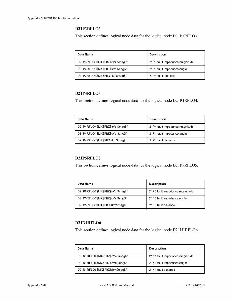
Appendix N IEC61850 Implementation
Appendix N-80 L-PRO 4000 User Manual D02706R02.51
D21P3RFLO3
This section defines logical node data for the logical node D21P3RFLO3.
D21P4RFLO4
This section defines logical node data for the logical node D21P4RFLO4.
D21P5RFLO5
This section defines logical node data for the logical node D21P5RFLO5.
D21N1RFLO6
This section defines logical node data for the logical node D21N1RFLO6.
Data Name Description
D21P3RFLO3$MX$FltZ$cVal$mag$f 21P3 fault impedance magnitude
D21P3RFLO3$MX$FltZ$cVal$ang$f 21P3 fault impedance angle
D21P3RFLO3$MX$FltDiskm$mag$f 21P3 fault distance
Data Name Description
D21P4RFLO4$MX$FltZ$cVal$mag$f 21P4 fault impedance magnitude
D21P4RFLO4$MX$FltZ$cVal$ang$f 21P4 fault impedance angle
D21P4RFLO4$MX$FltDiskm$mag$f 21P4 fault distance
Data Name Description
D21P5RFLO5$MX$FltZ$cVal$mag$f 21P5 fault impedance magnitude
D21P5RFLO5$MX$FltZ$cVal$ang$f 21P5 fault impedance angle
D21P5RFLO5$MX$FltDiskm$mag$f 21P5 fault distance
Data Name Description
D21N1RFLO6$MX$FltZ$cVal$mag$f 21N1 fault impedance magnitude
D21N1RFLO6$MX$FltZ$cVal$ang$f 21N1 fault impedance angle
D21N1RFLO6$MX$FltDiskm$mag$f 21N1 fault distance
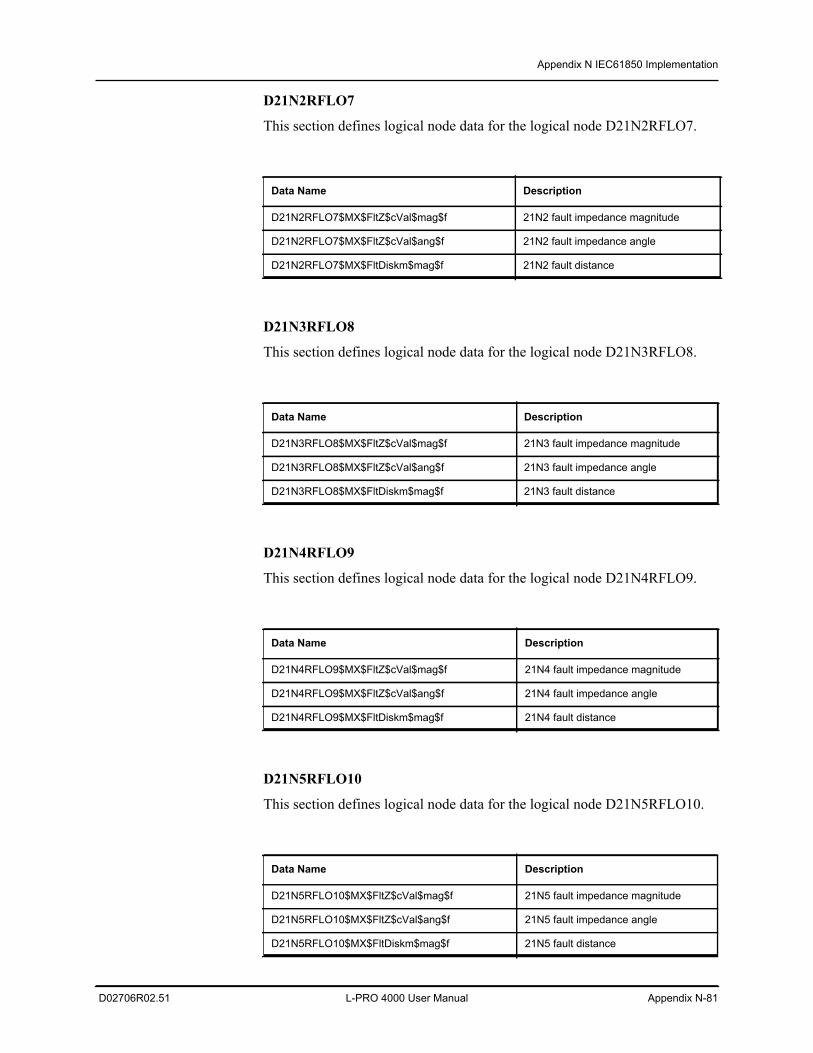
Appendix N IEC61850 Implementation
D02706R02.51 L-PRO 4000 User Manual Appendix N-81
D21N2RFLO7
This section defines logical node data for the logical node D21N2RFLO7.
D21N3RFLO8
This section defines logical node data for the logical node D21N3RFLO8.
D21N4RFLO9
This section defines logical node data for the logical node D21N4RFLO9.
D21N5RFLO10
This section defines logical node data for the logical node D21N5RFLO10.
Data Name Description
D21N2RFLO7$MX$FltZ$cVal$mag$f 21N2 fault impedance magnitude
D21N2RFLO7$MX$FltZ$cVal$ang$f 21N2 fault impedance angle
D21N2RFLO7$MX$FltDiskm$mag$f 21N2 fault distance
Data Name Description
D21N3RFLO8$MX$FltZ$cVal$mag$f 21N3 fault impedance magnitude
D21N3RFLO8$MX$FltZ$cVal$ang$f 21N3 fault impedance angle
D21N3RFLO8$MX$FltDiskm$mag$f 21N3 fault distance
Data Name Description
D21N4RFLO9$MX$FltZ$cVal$mag$f 21N4 fault impedance magnitude
D21N4RFLO9$MX$FltZ$cVal$ang$f 21N4 fault impedance angle
D21N4RFLO9$MX$FltDiskm$mag$f 21N4 fault distance
Data Name Description
D21N5RFLO10$MX$FltZ$cVal$mag$f 21N5 fault impedance magnitude
D21N5RFLO10$MX$FltZ$cVal$ang$f 21N5 fault impedance angle
D21N5RFLO10$MX$FltDiskm$mag$f 21N5 fault distance
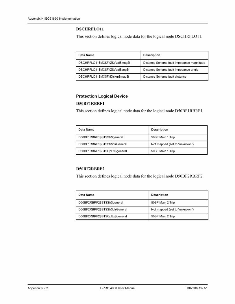
Appendix N IEC61850 Implementation
Appendix N-82 L-PRO 4000 User Manual D02706R02.51
DSCHRFLO11
This section defines logical node data for the logical node DSCHRFLO11.
Protection Logical Device D50BF1RBRF1
This section defines logical node data for the logical node D50BF1RBRF1.
D50BF2RBRF2
This section defines logical node data for the logical node D50BF2RBRF2.
Data Name Description
DSCHRFLO11$MX$FltZ$cVal$mag$f Distance Scheme fault impedance magnitude
DSCHRFLO11$MX$FltZ$cVal$ang$f Distance Scheme fault impedance angle
DSCHRFLO11$MX$FltDiskm$mag$f Distance Scheme fault distance
Data Name Description
D50BF1RBRF1$ST$Str$general 50BF Main 1 Trip
D50BF1RBRF1$ST$Str$dirGeneral Not mapped (set to “unknown”)
D50BF1RBRF1$ST$OpEx$general 50BF Main 1 Trip
Data Name Description
D50BF2RBRF2$ST$Str$general 50BF Main 2 Trip
D50BF2RBRF2$ST$Str$dirGeneral Not mapped (set to “unknown”)
D50BF2RBRF2$ST$OpEx$general 50BF Main 2 Trip
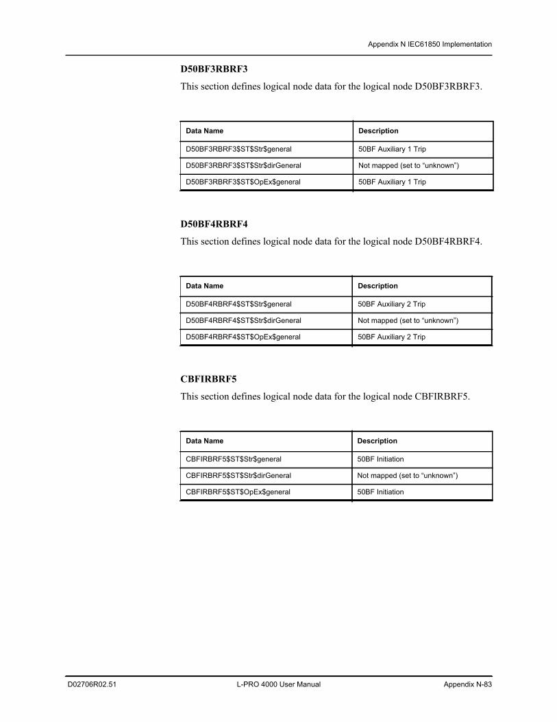
Appendix N IEC61850 Implementation
D02706R02.51 L-PRO 4000 User Manual Appendix N-83
D50BF3RBRF3
This section defines logical node data for the logical node D50BF3RBRF3.
D50BF4RBRF4
This section defines logical node data for the logical node D50BF4RBRF4.
CBFIRBRF5
This section defines logical node data for the logical node CBFIRBRF5.
Data Name Description
D50BF3RBRF3$ST$Str$general 50BF Auxiliary 1 Trip
D50BF3RBRF3$ST$Str$dirGeneral Not mapped (set to “unknown”)
D50BF3RBRF3$ST$OpEx$general 50BF Auxiliary 1 Trip
Data Name Description
D50BF4RBRF4$ST$Str$general 50BF Auxiliary 2 Trip
D50BF4RBRF4$ST$Str$dirGeneral Not mapped (set to “unknown”)
D50BF4RBRF4$ST$OpEx$general 50BF Auxiliary 2 Trip
Data Name Description
CBFIRBRF5$ST$Str$general 50BF Initiation
CBFIRBRF5$ST$Str$dirGeneral Not mapped (set to “unknown”)
CBFIRBRF5$ST$OpEx$general 50BF Initiation
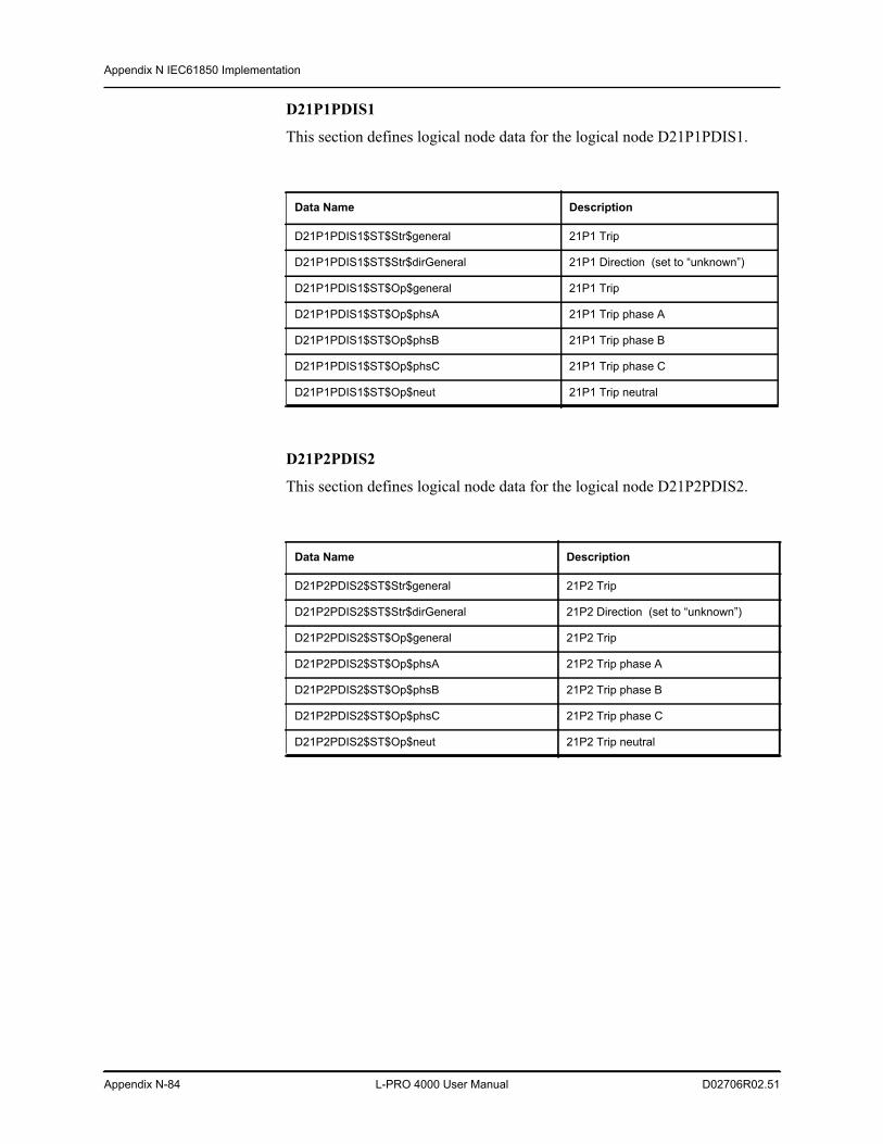
Appendix N IEC61850 Implementation
Appendix N-84 L-PRO 4000 User Manual D02706R02.51
D21P1PDIS1
This section defines logical node data for the logical node D21P1PDIS1.
D21P2PDIS2
This section defines logical node data for the logical node D21P2PDIS2.
Data Name Description
D21P1PDIS1$ST$Str$general 21P1 Trip
D21P1PDIS1$ST$Str$dirGeneral 21P1 Direction (set to “unknown”)
D21P1PDIS1$ST$Op$general 21P1 Trip
D21P1PDIS1$ST$Op$phsA 21P1 Trip phase A
D21P1PDIS1$ST$Op$phsB 21P1 Trip phase B
D21P1PDIS1$ST$Op$phsC 21P1 Trip phase C
D21P1PDIS1$ST$Op$neut 21P1 Trip neutral
Data Name Description
D21P2PDIS2$ST$Str$general 21P2 Trip
D21P2PDIS2$ST$Str$dirGeneral 21P2 Direction (set to “unknown”)
D21P2PDIS2$ST$Op$general 21P2 Trip
D21P2PDIS2$ST$Op$phsA 21P2 Trip phase A
D21P2PDIS2$ST$Op$phsB 21P2 Trip phase B
D21P2PDIS2$ST$Op$phsC 21P2 Trip phase C
D21P2PDIS2$ST$Op$neut 21P2 Trip neutral
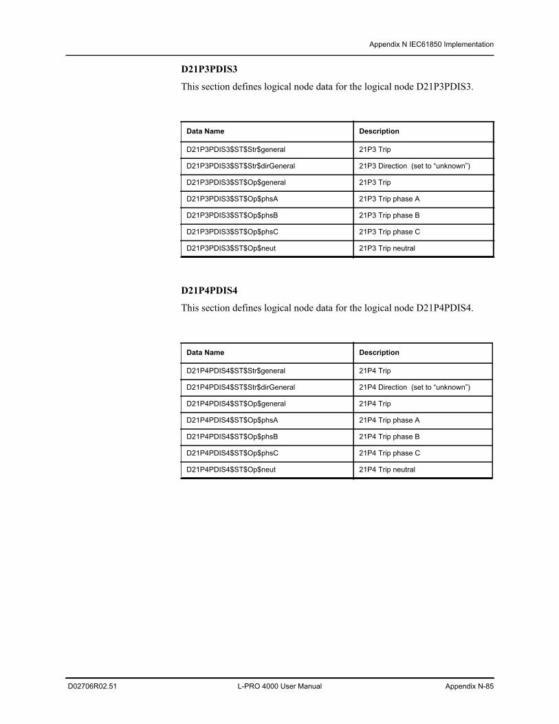
Appendix N IEC61850 Implementation
D02706R02.51 L-PRO 4000 User Manual Appendix N-85
D21P3PDIS3
This section defines logical node data for the logical node D21P3PDIS3.
D21P4PDIS4
This section defines logical node data for the logical node D21P4PDIS4.
Data Name Description
D21P3PDIS3$ST$Str$general 21P3 Trip
D21P3PDIS3$ST$Str$dirGeneral 21P3 Direction (set to “unknown”)
D21P3PDIS3$ST$Op$general 21P3 Trip
D21P3PDIS3$ST$Op$phsA 21P3 Trip phase A
D21P3PDIS3$ST$Op$phsB 21P3 Trip phase B
D21P3PDIS3$ST$Op$phsC 21P3 Trip phase C
D21P3PDIS3$ST$Op$neut 21P3 Trip neutral
Data Name Description
D21P4PDIS4$ST$Str$general 21P4 Trip
D21P4PDIS4$ST$Str$dirGeneral 21P4 Direction (set to “unknown”)
D21P4PDIS4$ST$Op$general 21P4 Trip
D21P4PDIS4$ST$Op$phsA 21P4 Trip phase A
D21P4PDIS4$ST$Op$phsB 21P4 Trip phase B
D21P4PDIS4$ST$Op$phsC 21P4 Trip phase C
D21P4PDIS4$ST$Op$neut 21P4 Trip neutral
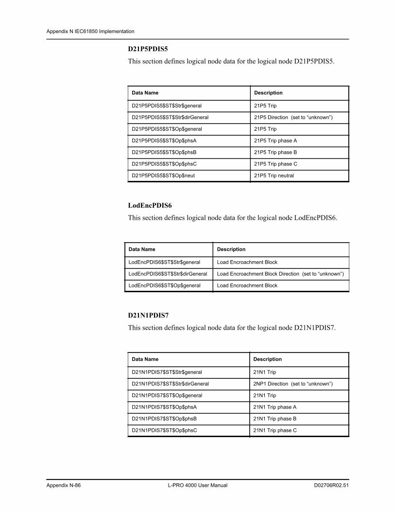
Appendix N IEC61850 Implementation
Appendix N-86 L-PRO 4000 User Manual D02706R02.51
D21P5PDIS5
This section defines logical node data for the logical node D21P5PDIS5.
LodEncPDIS6
This section defines logical node data for the logical node LodEncPDIS6.
D21N1PDIS7
This section defines logical node data for the logical node D21N1PDIS7.
Data Name Description
D21P5PDIS5$ST$Str$general 21P5 Trip
D21P5PDIS5$ST$Str$dirGeneral 21P5 Direction (set to “unknown”)
D21P5PDIS5$ST$Op$general 21P5 Trip
D21P5PDIS5$ST$Op$phsA 21P5 Trip phase A
D21P5PDIS5$ST$Op$phsB 21P5 Trip phase B
D21P5PDIS5$ST$Op$phsC 21P5 Trip phase C
D21P5PDIS5$ST$Op$neut 21P5 Trip neutral
Data Name Description
LodEncPDIS6$ST$Str$general Load Encroachment Block
LodEncPDIS6$ST$Str$dirGeneral Load Encroachment Block Direction (set to “unknown”)
LodEncPDIS6$ST$Op$general Load Encroachment Block
Data Name Description
D21N1PDIS7$ST$Str$general 21N1 Trip
D21N1PDIS7$ST$Str$dirGeneral 2NP1 Direction (set to “unknown”)
D21N1PDIS7$ST$Op$general 21N1 Trip
D21N1PDIS7$ST$Op$phsA 21N1 Trip phase A
D21N1PDIS7$ST$Op$phsB 21N1 Trip phase B
D21N1PDIS7$ST$Op$phsC 21N1 Trip phase C
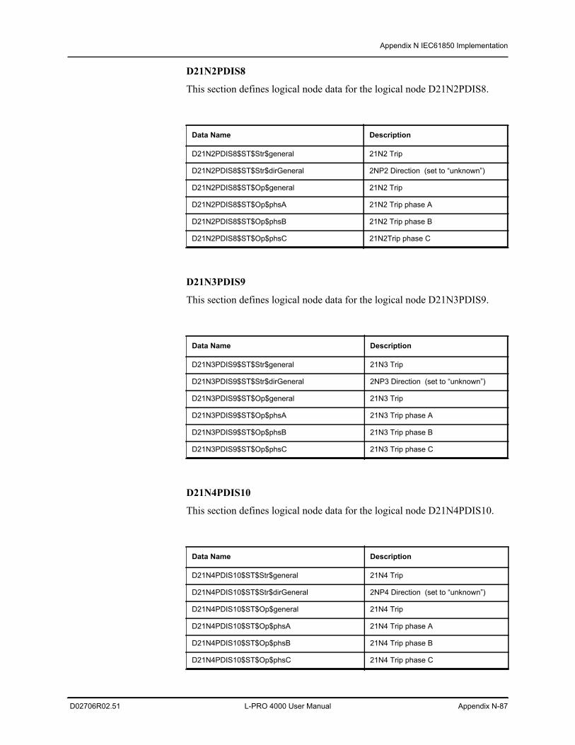
Appendix N IEC61850 Implementation
D02706R02.51 L-PRO 4000 User Manual Appendix N-87
D21N2PDIS8
This section defines logical node data for the logical node D21N2PDIS8.
D21N3PDIS9
This section defines logical node data for the logical node D21N3PDIS9.
D21N4PDIS10
This section defines logical node data for the logical node D21N4PDIS10.
Data Name Description
D21N2PDIS8$ST$Str$general 21N2 Trip
D21N2PDIS8$ST$Str$dirGeneral 2NP2 Direction (set to “unknown”)
D21N2PDIS8$ST$Op$general 21N2 Trip
D21N2PDIS8$ST$Op$phsA 21N2 Trip phase A
D21N2PDIS8$ST$Op$phsB 21N2 Trip phase B
D21N2PDIS8$ST$Op$phsC 21N2Trip phase C
Data Name Description
D21N3PDIS9$ST$Str$general 21N3 Trip
D21N3PDIS9$ST$Str$dirGeneral 2NP3 Direction (set to “unknown”)
D21N3PDIS9$ST$Op$general 21N3 Trip
D21N3PDIS9$ST$Op$phsA 21N3 Trip phase A
D21N3PDIS9$ST$Op$phsB 21N3 Trip phase B
D21N3PDIS9$ST$Op$phsC 21N3 Trip phase C
Data Name Description
D21N4PDIS10$ST$Str$general 21N4 Trip
D21N4PDIS10$ST$Str$dirGeneral 2NP4 Direction (set to “unknown”)
D21N4PDIS10$ST$Op$general 21N4 Trip
D21N4PDIS10$ST$Op$phsA 21N4 Trip phase A
D21N4PDIS10$ST$Op$phsB 21N4 Trip phase B
D21N4PDIS10$ST$Op$phsC 21N4 Trip phase C
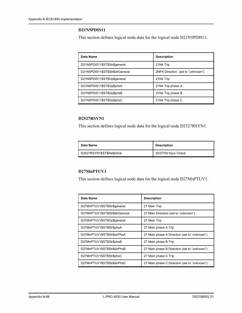
Appendix N IEC61850 Implementation
Appendix N-88 L-PRO 4000 User Manual D02706R02.51
D21N5PDIS11
This section defines logical node data for the logical node D21N5PDIS11.
D2527RSYN1
This section defines logical node data for the logical node D2527RSYN1.
D27MnPTUV1
This section defines logical node data for the logical node D27MnPTUV1.
Data Name Description
D21N5PDIS11$ST$Str$general 21N4 Trip
D21N5PDIS11$ST$Str$dirGeneral 2NP4 Direction (set to “unknown”)
D21N5PDIS11$ST$Op$general 21N4 Trip
D21N5PDIS11$ST$Op$phsA 21N4 Trip phase A
D21N5PDIS11$ST$Op$phsB 21N4 Trip phase B
D21N5PDIS11$ST$Op$phsC 21N4 Trip phase C
Data Name Description
D2527RSYN1$ST$Rel$stVal 25/27/59 Sync Check
Data Name Description
D27MnPTUV1$ST$Str$general 27 Main Trip
D27MnPTUV1$ST$Str$dirGeneral 27 Main Direction (set to “unknown”)
D27MnPTUV1$ST$Op$general 27 Main Trip
D27MnPTUV1$ST$Str$phsA 27 Main phase A Trip
D27MnPTUV1$ST$Str$dirPhsA 27 Main phase A Direction (set to “unknown”)
D27MnPTUV1$ST$Str$phsB 27 Main phase B Trip
D27MnPTUV1$ST$Str$dirPhsB 27 Main phase B Direction (set to “unknown”)
D27MnPTUV1$ST$Str$phsC 27 Main phase C Trip
D27MnPTUV1$ST$Str$dirPhsC 27 Main phase C Direction (set to “unknown”)
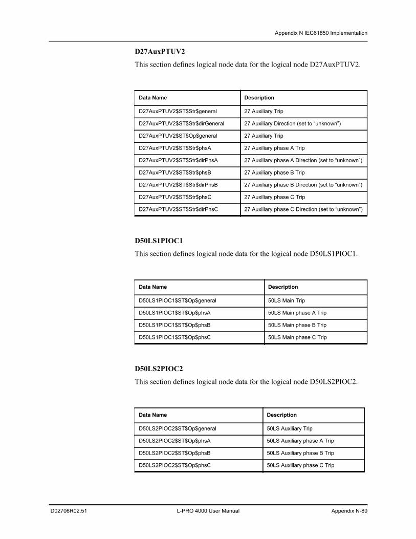
Appendix N IEC61850 Implementation
D02706R02.51 L-PRO 4000 User Manual Appendix N-89
D27AuxPTUV2
This section defines logical node data for the logical node D27AuxPTUV2.
D50LS1PIOC1
This section defines logical node data for the logical node D50LS1PIOC1.
D50LS2PIOC2
This section defines logical node data for the logical node D50LS2PIOC2.
Data Name Description
D27AuxPTUV2$ST$Str$general 27 Auxiliary Trip
D27AuxPTUV2$ST$Str$dirGeneral 27 Auxiliary Direction (set to “unknown”)
D27AuxPTUV2$ST$Op$general 27 Auxiliary Trip
D27AuxPTUV2$ST$Str$phsA 27 Auxiliary phase A Trip
D27AuxPTUV2$ST$Str$dirPhsA 27 Auxiliary phase A Direction (set to “unknown”)
D27AuxPTUV2$ST$Str$phsB 27 Auxiliary phase B Trip
D27AuxPTUV2$ST$Str$dirPhsB 27 Auxiliary phase B Direction (set to “unknown”)
D27AuxPTUV2$ST$Str$phsC 27 Auxiliary phase C Trip
D27AuxPTUV2$ST$Str$dirPhsC 27 Auxiliary phase C Direction (set to “unknown”)
Data Name Description
D50LS1PIOC1$ST$Op$general 50LS Main Trip
D50LS1PIOC1$ST$Op$phsA 50LS Main phase A Trip
D50LS1PIOC1$ST$Op$phsB 50LS Main phase B Trip
D50LS1PIOC1$ST$Op$phsC 50LS Main phase C Trip
Data Name Description
D50LS2PIOC2$ST$Op$general 50LS Auxiliary Trip
D50LS2PIOC2$ST$Op$phsA 50LS Auxiliary phase A Trip
D50LS2PIOC2$ST$Op$phsB 50LS Auxiliary phase B Trip
D50LS2PIOC2$ST$Op$phsC 50LS Auxiliary phase C Trip
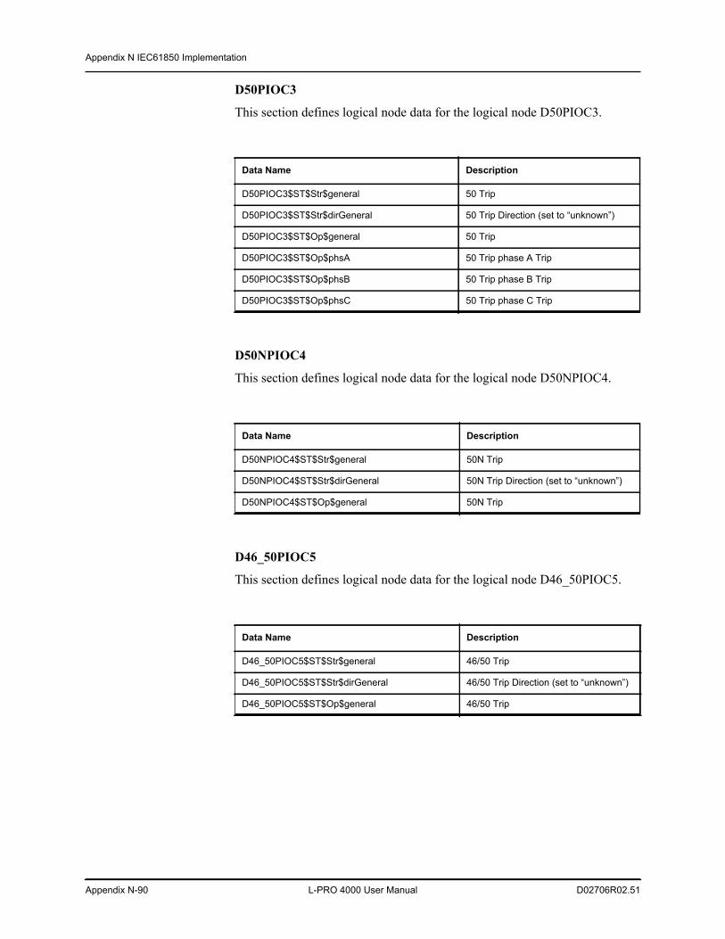
Appendix N IEC61850 Implementation
Appendix N-90 L-PRO 4000 User Manual D02706R02.51
D50PIOC3
This section defines logical node data for the logical node D50PIOC3.
D50NPIOC4
This section defines logical node data for the logical node D50NPIOC4.
D46_50PIOC5
This section defines logical node data for the logical node D46_50PIOC5.
Data Name Description
D50PIOC3$ST$Str$general 50 Trip
D50PIOC3$ST$Str$dirGeneral 50 Trip Direction (set to “unknown”)
D50PIOC3$ST$Op$general 50 Trip
D50PIOC3$ST$Op$phsA 50 Trip phase A Trip
D50PIOC3$ST$Op$phsB 50 Trip phase B Trip
D50PIOC3$ST$Op$phsC 50 Trip phase C Trip
Data Name Description
D50NPIOC4$ST$Str$general 50N Trip
D50NPIOC4$ST$Str$dirGeneral 50N Trip Direction (set to “unknown”)
D50NPIOC4$ST$Op$general 50N Trip
Data Name Description
D46_50PIOC5$ST$Str$general 46/50 Trip
D46_50PIOC5$ST$Str$dirGeneral 46/50 Trip Direction (set to “unknown”)
D46_50PIOC5$ST$Op$general 46/50 Trip
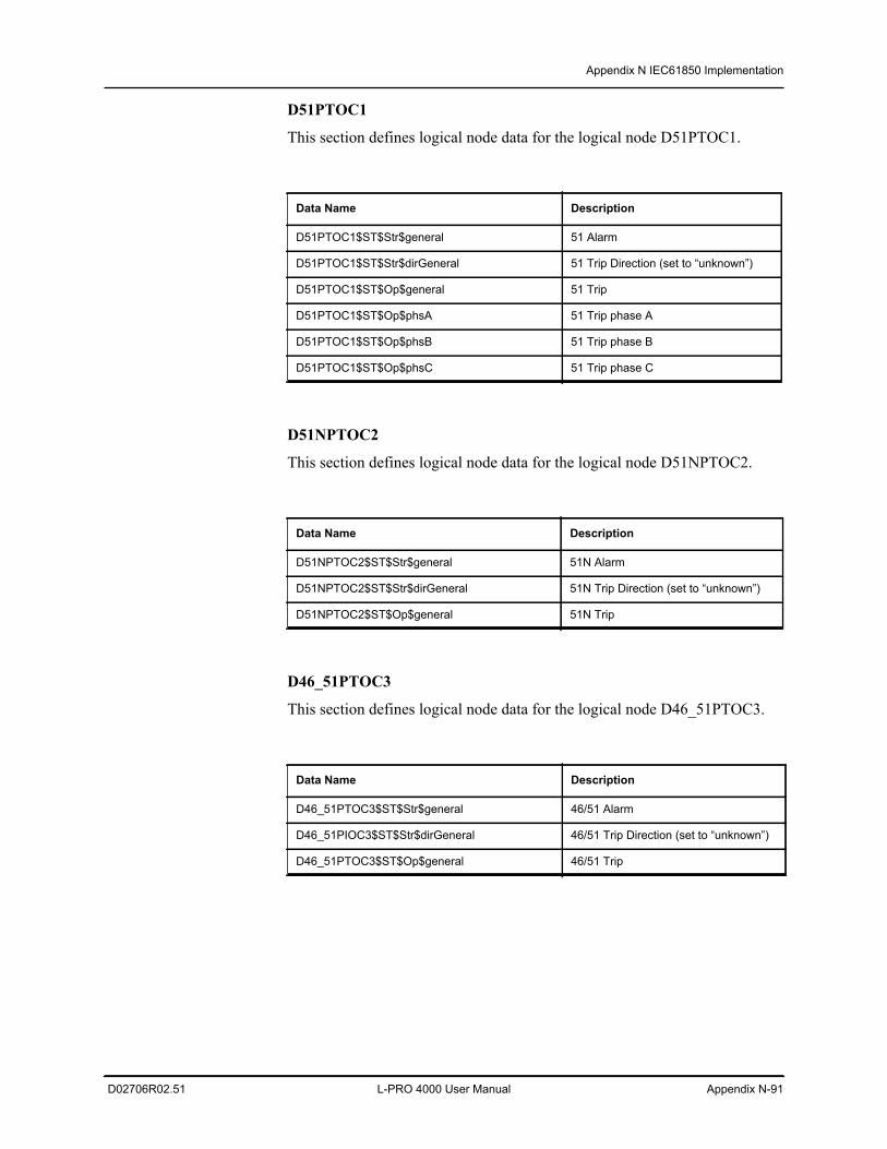
Appendix N IEC61850 Implementation
D02706R02.51 L-PRO 4000 User Manual Appendix N-91
D51PTOC1
This section defines logical node data for the logical node D51PTOC1.
D51NPTOC2
This section defines logical node data for the logical node D51NPTOC2.
D46_51PTOC3
This section defines logical node data for the logical node D46_51PTOC3.
Data Name Description
D51PTOC1$ST$Str$general 51 Alarm
D51PTOC1$ST$Str$dirGeneral 51 Trip Direction (set to “unknown”)
D51PTOC1$ST$Op$general 51 Trip
D51PTOC1$ST$Op$phsA 51 Trip phase A
D51PTOC1$ST$Op$phsB 51 Trip phase B
D51PTOC1$ST$Op$phsC 51 Trip phase C
Data Name Description
D51NPTOC2$ST$Str$general 51N Alarm
D51NPTOC2$ST$Str$dirGeneral 51N Trip Direction (set to “unknown”)
D51NPTOC2$ST$Op$general 51N Trip
Data Name Description
D46_51PTOC3$ST$Str$general 46/51 Alarm
D46_51PIOC3$ST$Str$dirGeneral 46/51 Trip Direction (set to “unknown”)
D46_51PTOC3$ST$Op$general 46/51 Trip
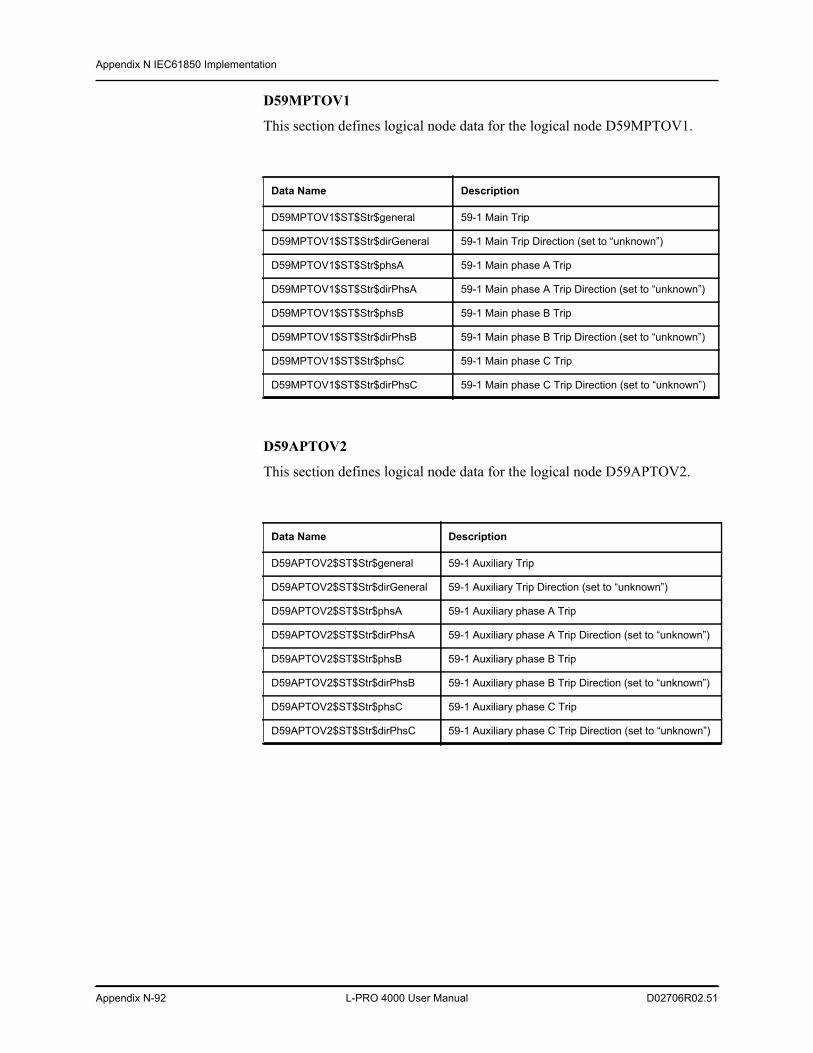
Appendix N IEC61850 Implementation
Appendix N-92 L-PRO 4000 User Manual D02706R02.51
D59MPTOV1
This section defines logical node data for the logical node D59MPTOV1.
D59APTOV2
This section defines logical node data for the logical node D59APTOV2.
Data Name Description
D59MPTOV1$ST$Str$general 59-1 Main Trip
D59MPTOV1$ST$Str$dirGeneral 59-1 Main Trip Direction (set to “unknown”)
D59MPTOV1$ST$Str$phsA 59-1 Main phase A Trip
D59MPTOV1$ST$Str$dirPhsA 59-1 Main phase A Trip Direction (set to “unknown”)
D59MPTOV1$ST$Str$phsB 59-1 Main phase B Trip
D59MPTOV1$ST$Str$dirPhsB 59-1 Main phase B Trip Direction (set to “unknown”)
D59MPTOV1$ST$Str$phsC 59-1 Main phase C Trip
D59MPTOV1$ST$Str$dirPhsC 59-1 Main phase C Trip Direction (set to “unknown”)
Data Name Description
D59APTOV2$ST$Str$general 59-1 Auxiliary Trip
D59APTOV2$ST$Str$dirGeneral 59-1 Auxiliary Trip Direction (set to “unknown”)
D59APTOV2$ST$Str$phsA 59-1 Auxiliary phase A Trip
D59APTOV2$ST$Str$dirPhsA 59-1 Auxiliary phase A Trip Direction (set to “unknown”)
D59APTOV2$ST$Str$phsB 59-1 Auxiliary phase B Trip
D59APTOV2$ST$Str$dirPhsB 59-1 Auxiliary phase B Trip Direction (set to “unknown”)
D59APTOV2$ST$Str$phsC 59-1 Auxiliary phase C Trip
D59APTOV2$ST$Str$dirPhsC 59-1 Auxiliary phase C Trip Direction (set to “unknown”)
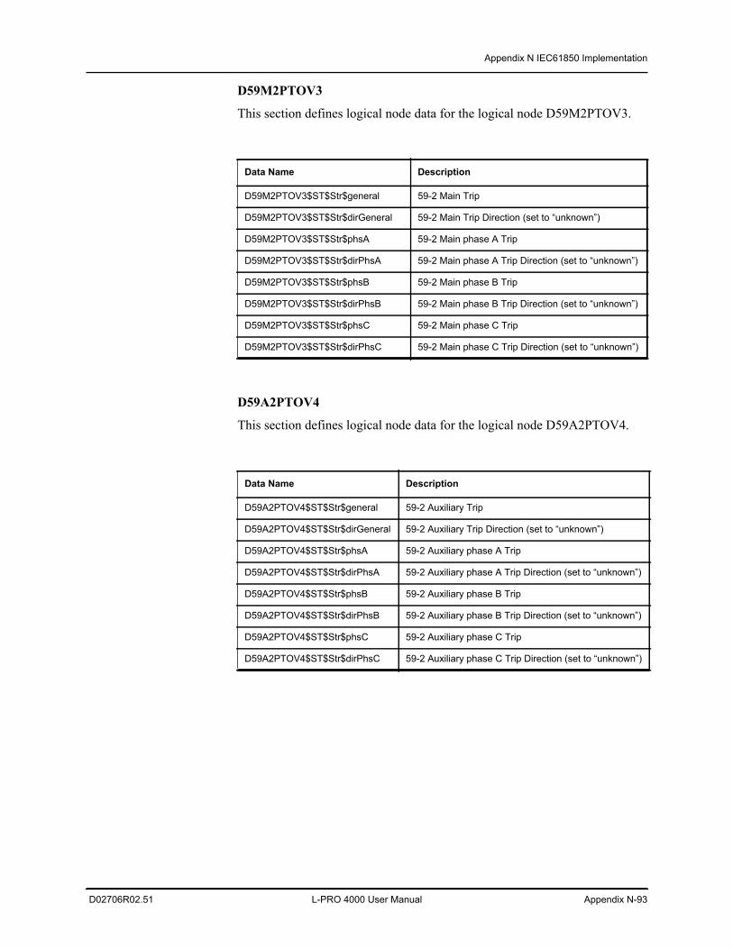
Appendix N IEC61850 Implementation
D02706R02.51 L-PRO 4000 User Manual Appendix N-93
D59M2PTOV3
This section defines logical node data for the logical node D59M2PTOV3.
D59A2PTOV4
This section defines logical node data for the logical node D59A2PTOV4.
Data Name Description
D59M2PTOV3$ST$Str$general 59-2 Main Trip
D59M2PTOV3$ST$Str$dirGeneral 59-2 Main Trip Direction (set to “unknown”)
D59M2PTOV3$ST$Str$phsA 59-2 Main phase A Trip
D59M2PTOV3$ST$Str$dirPhsA 59-2 Main phase A Trip Direction (set to “unknown”)
D59M2PTOV3$ST$Str$phsB 59-2 Main phase B Trip
D59M2PTOV3$ST$Str$dirPhsB 59-2 Main phase B Trip Direction (set to “unknown”)
D59M2PTOV3$ST$Str$phsC 59-2 Main phase C Trip
D59M2PTOV3$ST$Str$dirPhsC 59-2 Main phase C Trip Direction (set to “unknown”)
Data Name Description
D59A2PTOV4$ST$Str$general 59-2 Auxiliary Trip
D59A2PTOV4$ST$Str$dirGeneral 59-2 Auxiliary Trip Direction (set to “unknown”)
D59A2PTOV4$ST$Str$phsA 59-2 Auxiliary phase A Trip
D59A2PTOV4$ST$Str$dirPhsA 59-2 Auxiliary phase A Trip Direction (set to “unknown”)
D59A2PTOV4$ST$Str$phsB 59-2 Auxiliary phase B Trip
D59A2PTOV4$ST$Str$dirPhsB 59-2 Auxiliary phase B Trip Direction (set to “unknown”)
D59A2PTOV4$ST$Str$phsC 59-2 Auxiliary phase C Trip
D59A2PTOV4$ST$Str$dirPhsC 59-2 Auxiliary phase C Trip Direction (set to “unknown”)
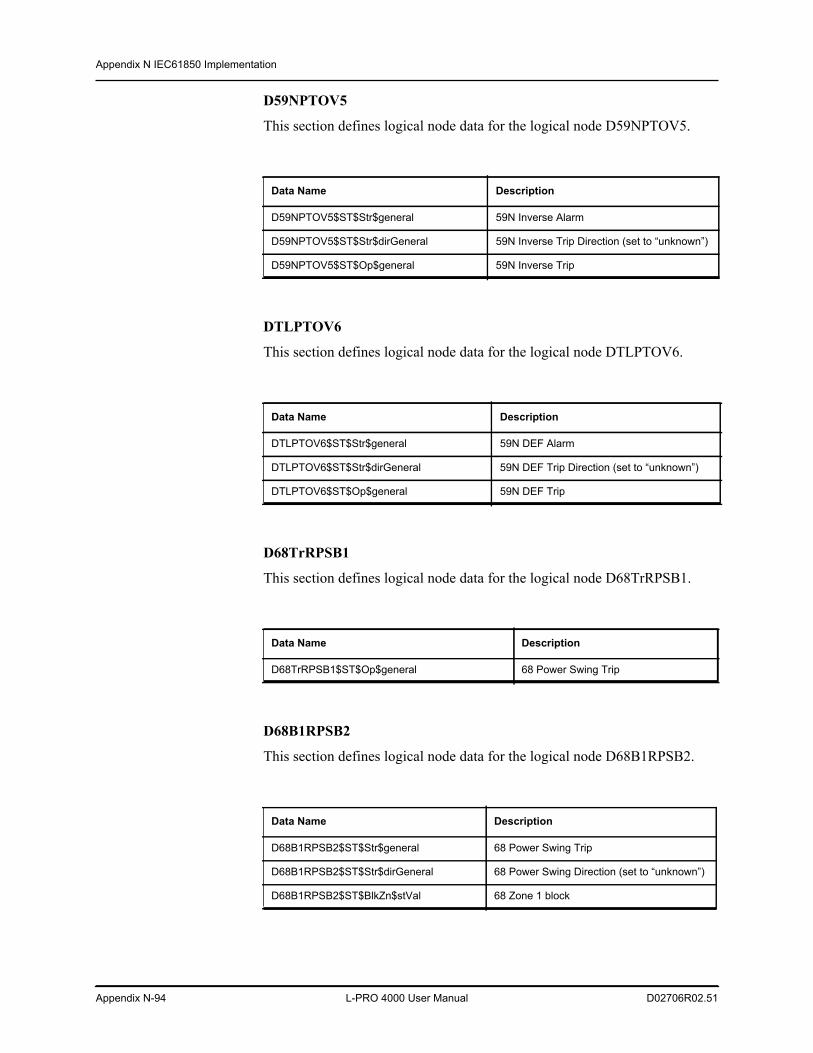
Appendix N IEC61850 Implementation
Appendix N-94 L-PRO 4000 User Manual D02706R02.51
D59NPTOV5
This section defines logical node data for the logical node D59NPTOV5.
DTLPTOV6
This section defines logical node data for the logical node DTLPTOV6.
D68TrRPSB1
This section defines logical node data for the logical node D68TrRPSB1.
D68B1RPSB2
This section defines logical node data for the logical node D68B1RPSB2.
Data Name Description
D59NPTOV5$ST$Str$general 59N Inverse Alarm
D59NPTOV5$ST$Str$dirGeneral 59N Inverse Trip Direction (set to “unknown”)
D59NPTOV5$ST$Op$general 59N Inverse Trip
Data Name Description
DTLPTOV6$ST$Str$general 59N DEF Alarm
DTLPTOV6$ST$Str$dirGeneral 59N DEF Trip Direction (set to “unknown”)
DTLPTOV6$ST$Op$general 59N DEF Trip
Data Name Description
D68TrRPSB1$ST$Op$general 68 Power Swing Trip
Data Name Description
D68B1RPSB2$ST$Str$general 68 Power Swing Trip
D68B1RPSB2$ST$Str$dirGeneral 68 Power Swing Direction (set to “unknown”)
D68B1RPSB2$ST$BlkZn$stVal 68 Zone 1 block
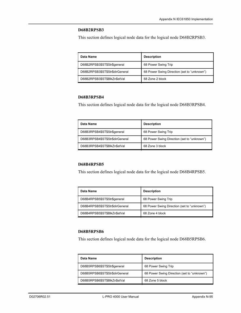
Appendix N IEC61850 Implementation
D02706R02.51 L-PRO 4000 User Manual Appendix N-95
D68B2RPSB3
This section defines logical node data for the logical node D68B2RPSB3.
D68B3RPSB4
This section defines logical node data for the logical node D68B3RPSB4.
D68B4RPSB5
This section defines logical node data for the logical node D68B4RPSB5.
D68B5RPSB6
This section defines logical node data for the logical node D68B5RPSB6.
Data Name Description
D68B2RPSB3$ST$Str$general 68 Power Swing Trip
D68B2RPSB3$ST$Str$dirGeneral 68 Power Swing Direction (set to “unknown”)
D68B2RPSB3$ST$BlkZn$stVal 68 Zone 2 block
Data Name Description
D68B3RPSB4$ST$Str$general 68 Power Swing Trip
D68B3RPSB4$ST$Str$dirGeneral 68 Power Swing Direction (set to “unknown”)
D68B3RPSB4$ST$BlkZn$stVal 68 Zone 3 block
Data Name Description
D68B4RPSB5$ST$Str$general 68 Power Swing Trip
D68B4RPSB5$ST$Str$dirGeneral 68 Power Swing Direction (set to “unknown”)
D68B4RPSB5$ST$BlkZn$stVal 68 Zone 4 block
Data Name Description
D68B5RPSB6$ST$Str$general 68 Power Swing Trip
D68B5RPSB6$ST$Str$dirGeneral 68 Power Swing Direction (set to “unknown”)
D68B5RPSB6$ST$BlkZn$stVal 68 Zone 5 block
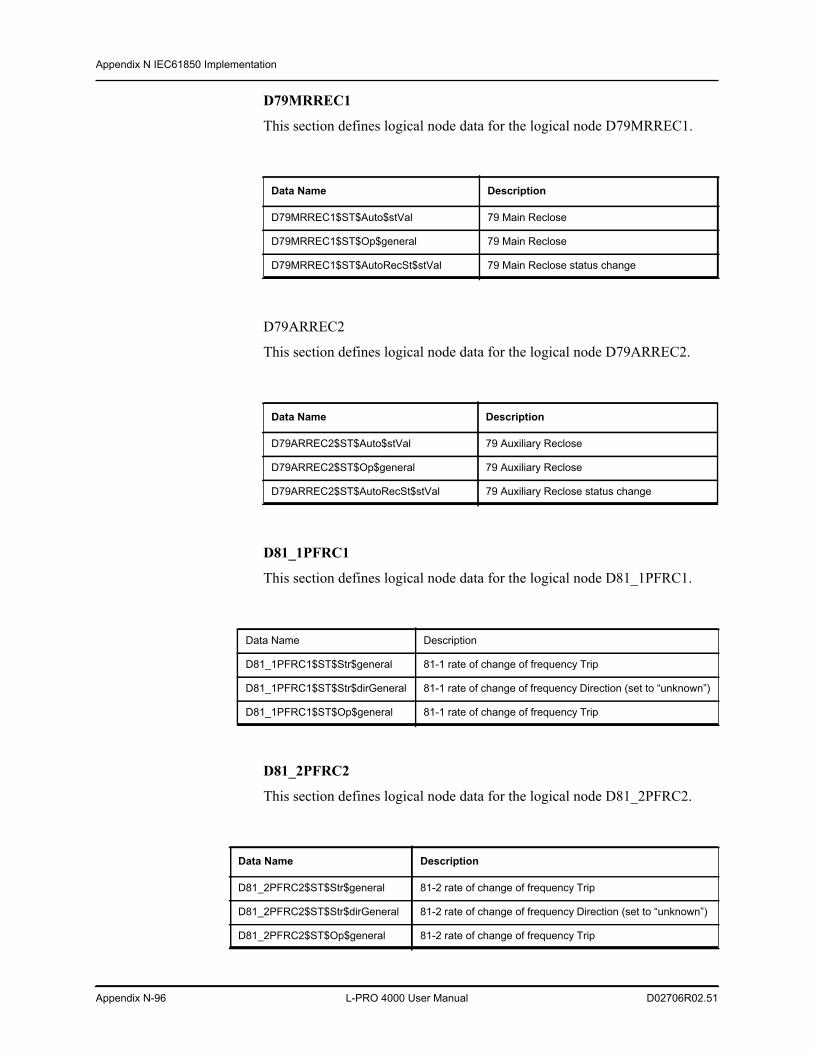
Appendix N IEC61850 Implementation
Appendix N-96 L-PRO 4000 User Manual D02706R02.51
D79MRREC1
This section defines logical node data for the logical node D79MRREC1.
D79ARREC2
This section defines logical node data for the logical node D79ARREC2.
D81_1PFRC1
This section defines logical node data for the logical node D81_1PFRC1.
D81_2PFRC2
This section defines logical node data for the logical node D81_2PFRC2.
Data Name Description
D79MRREC1$ST$Auto$stVal 79 Main Reclose
D79MRREC1$ST$Op$general 79 Main Reclose
D79MRREC1$ST$AutoRecSt$stVal 79 Main Reclose status change
Data Name Description
D79ARREC2$ST$Auto$stVal 79 Auxiliary Reclose
D79ARREC2$ST$Op$general 79 Auxiliary Reclose
D79ARREC2$ST$AutoRecSt$stVal 79 Auxiliary Reclose status change
Data Name Description
D81_1PFRC1$ST$Str$general 81-1 rate of change of frequency Trip
D81_1PFRC1$ST$Str$dirGeneral 81-1 rate of change of frequency Direction (set to “unknown”)
D81_1PFRC1$ST$Op$general 81-1 rate of change of frequency Trip
Data Name Description
D81_2PFRC2$ST$Str$general 81-2 rate of change of frequency Trip
D81_2PFRC2$ST$Str$dirGeneral 81-2 rate of change of frequency Direction (set to “unknown”)
D81_2PFRC2$ST$Op$general 81-2 rate of change of frequency Trip
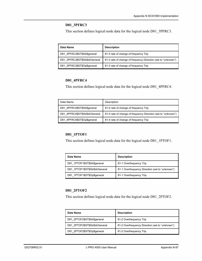
Appendix N IEC61850 Implementation
D02706R02.51 L-PRO 4000 User Manual Appendix N-97
D81_3PFRC3
This section defines logical node data for the logical node D81_3PFRC3.
D81_4PFRC4
This section defines logical node data for the logical node D81_4PFRC4.
D81_1PTOF1
This section defines logical node data for the logical node D81_1PTOF1.
D81_2PTOF2
This section defines logical node data for the logical node D81_2PTOF2.
Data Name Description
D81_3PFRC3$ST$Str$general 81-3 rate of change of frequency Trip
D81_3PFRC3$ST$Str$dirGeneral 81-3 rate of change of frequency Direction (set to “unknown”)
D81_3PFRC3$ST$Op$general 81-3 rate of change of frequency Trip
Data Name Description
D81_4PFRC4$ST$Str$general 81-4 rate of change of frequency Trip
D81_4PFRC4$ST$Str$dirGeneral 81-4 rate of change of frequency Direction (set to “unknown”)
D81_4PFRC4$ST$Op$general 81-4 rate of change of frequency Trip
Data Name Description
D81_1PTOF1$ST$Str$general 81-1 Overfrequency Trip
D81_1PTOF1$ST$Str$dirGeneral 81-1 Overfrequency Direction (set to “unknown”)
D81_1PTOF1$ST$Op$general 81-1 Overfrequency Trip
Data Name Description
D81_2PTOF2$ST$Str$general 81-2 Overfrequency Trip
D81_2PTOF2$ST$Str$dirGeneral 81-2 Overfrequency Direction (set to “unknown”)
D81_2PTOF2$ST$Op$general 81-2 Overfrequency Trip
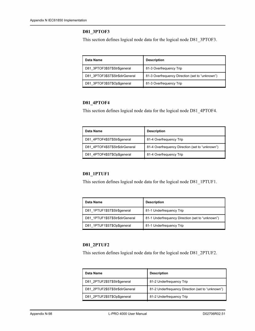
Appendix N IEC61850 Implementation
Appendix N-98 L-PRO 4000 User Manual D02706R02.51
D81_3PTOF3
This section defines logical node data for the logical node D81_3PTOF3.
D81_4PTOF4
This section defines logical node data for the logical node D81_4PTOF4.
D81_1PTUF1
This section defines logical node data for the logical node D81_1PTUF1.
D81_2PTUF2
This section defines logical node data for the logical node D81_2PTUF2.
Data Name Description
D81_3PTOF3$ST$Str$general 81-3 Overfrequency Trip
D81_3PTOF3$ST$Str$dirGeneral 81-3 Overfrequency Direction (set to “unknown”)
D81_3PTOF3$ST$Op$general 81-3 Overfrequency Trip
Data Name Description
D81_4PTOF4$ST$Str$general 81-4 Overfrequency Trip
D81_4PTOF4$ST$Str$dirGeneral 81-4 Overfrequency Direction (set to “unknown”)
D81_4PTOF4$ST$Op$general 81-4 Overfrequency Trip
Data Name Description
D81_1PTUF1$ST$Str$general 81-1 Underfrequency Trip
D81_1PTUF1$ST$Str$dirGeneral 81-1 Underfrequency Direction (set to “unknown”)
D81_1PTUF1$ST$Op$general 81-1 Underfrequency Trip
Data Name Description
D81_2PTUF2$ST$Str$general 81-2 Underfrequency Trip
D81_2PTUF2$ST$Str$dirGeneral 81-2 Underfrequency Direction (set to “unknown”)
D81_2PTUF2$ST$Op$general 81-2 Underfrequency Trip
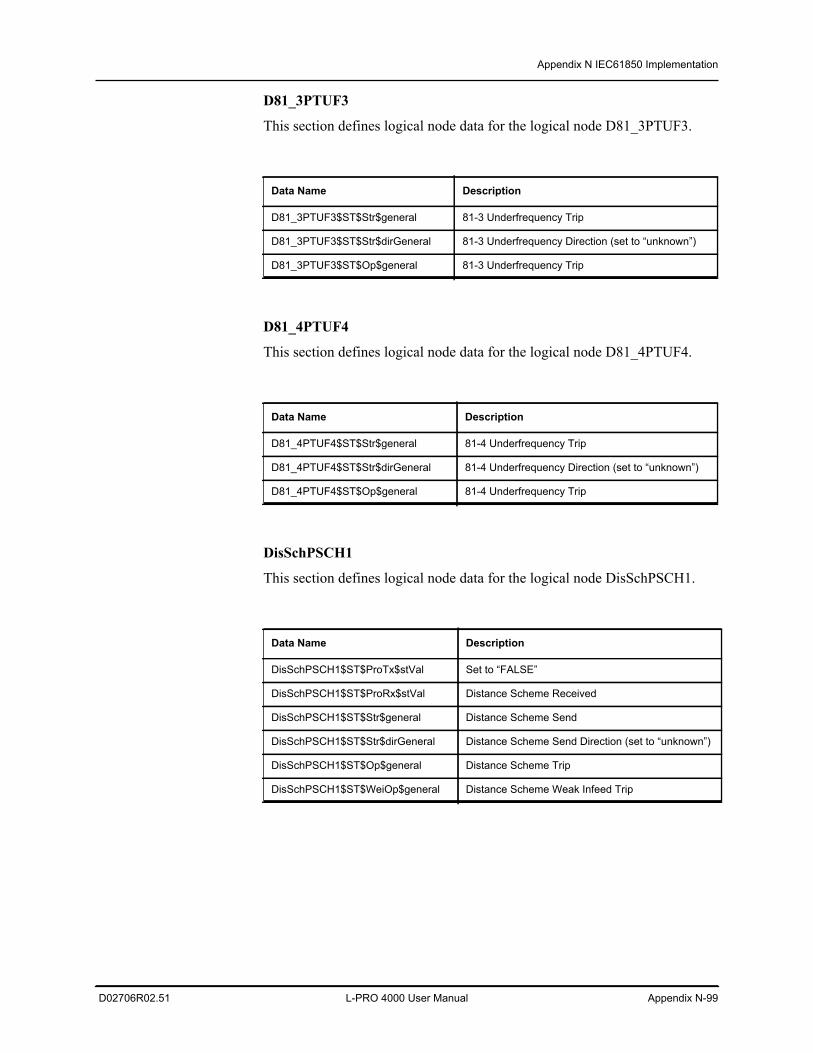
Appendix N IEC61850 Implementation
D02706R02.51 L-PRO 4000 User Manual Appendix N-99
D81_3PTUF3
This section defines logical node data for the logical node D81_3PTUF3.
D81_4PTUF4
This section defines logical node data for the logical node D81_4PTUF4.
DisSchPSCH1
This section defines logical node data for the logical node DisSchPSCH1.
Data Name Description
D81_3PTUF3$ST$Str$general 81-3 Underfrequency Trip
D81_3PTUF3$ST$Str$dirGeneral 81-3 Underfrequency Direction (set to “unknown”)
D81_3PTUF3$ST$Op$general 81-3 Underfrequency Trip
Data Name Description
D81_4PTUF4$ST$Str$general 81-4 Underfrequency Trip
D81_4PTUF4$ST$Str$dirGeneral 81-4 Underfrequency Direction (set to “unknown”)
D81_4PTUF4$ST$Op$general 81-4 Underfrequency Trip
Data Name Description
DisSchPSCH1$ST$ProTx$stVal Set to “FALSE”
DisSchPSCH1$ST$ProRx$stVal Distance Scheme Received
DisSchPSCH1$ST$Str$general Distance Scheme Send
DisSchPSCH1$ST$Str$dirGeneral Distance Scheme Send Direction (set to “unknown”)
DisSchPSCH1$ST$Op$general Distance Scheme Trip
DisSchPSCH1$ST$WeiOp$general Distance Scheme Weak Infeed Trip
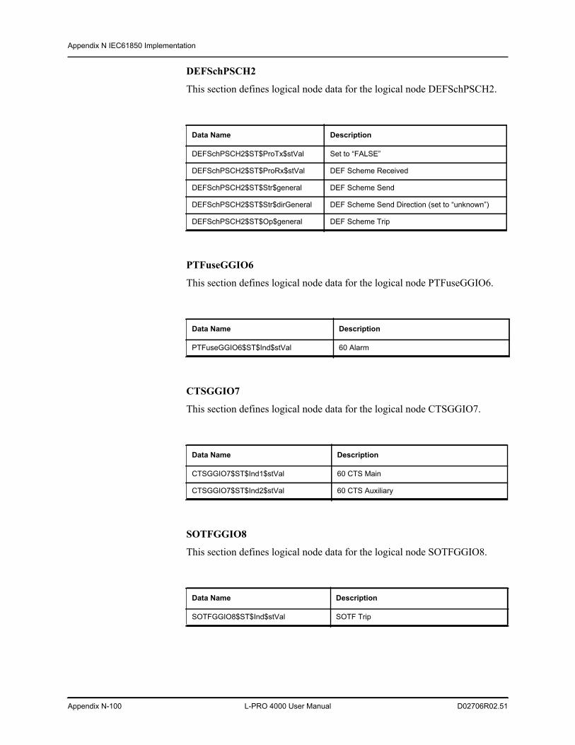
Appendix N IEC61850 Implementation
Appendix N-100 L-PRO 4000 User Manual D02706R02.51
DEFSchPSCH2
This section defines logical node data for the logical node DEFSchPSCH2.
PTFuseGGIO6
This section defines logical node data for the logical node PTFuseGGIO6.
CTSGGIO7
This section defines logical node data for the logical node CTSGGIO7.
SOTFGGIO8
This section defines logical node data for the logical node SOTFGGIO8.
Data Name Description
DEFSchPSCH2$ST$ProTx$stVal Set to “FALSE”
DEFSchPSCH2$ST$ProRx$stVal DEF Scheme Received
DEFSchPSCH2$ST$Str$general DEF Scheme Send
DEFSchPSCH2$ST$Str$dirGeneral DEF Scheme Send Direction (set to “unknown”)
DEFSchPSCH2$ST$Op$general DEF Scheme Trip
Data Name Description
PTFuseGGIO6$ST$Ind$stVal 60 Alarm
Data Name Description
CTSGGIO7$ST$Ind1$stVal 60 CTS Main
CTSGGIO7$ST$Ind2$stVal 60 CTS Auxiliary
Data Name Description
SOTFGGIO8$ST$Ind$stVal SOTF Trip
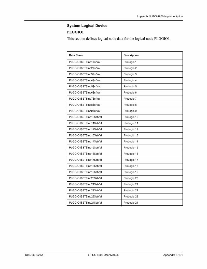
Appendix N IEC61850 Implementation
D02706R02.51 L-PRO 4000 User Manual Appendix N-101
System Logical Device PLGGIO1
This section defines logical node data for the logical node PLGGIO1.
Data Name Description
PLGGIO1$ST$Ind1$stVal ProLogic 1
PLGGIO1$ST$Ind2$stVal ProLogic 2
PLGGIO1$ST$Ind3$stVal ProLogic 3
PLGGIO1$ST$Ind4$stVal ProLogic 4
PLGGIO1$ST$Ind5$stVal ProLogic 5
PLGGIO1$ST$Ind6$stVal ProLogic 6
PLGGIO1$ST$Ind7$stVal ProLogic 7
PLGGIO1$ST$Ind8$stVal ProLogic 8
PLGGIO1$ST$Ind9$stVal ProLogic 9
PLGGIO1$ST$Ind10$stVal ProLogic 10
PLGGIO1$ST$Ind11$stVal ProLogic 11
PLGGIO1$ST$Ind12$stVal ProLogic 12
PLGGIO1$ST$Ind13$stVal ProLogic 13
PLGGIO1$ST$Ind14$stVal ProLogic 14
PLGGIO1$ST$Ind15$stVal ProLogic 15
PLGGIO1$ST$Ind16$stVal ProLogic 16
PLGGIO1$ST$Ind17$stVal ProLogic 17
PLGGIO1$ST$Ind18$stVal ProLogic 18
PLGGIO1$ST$Ind19$stVal ProLogic 19
PLGGIO1$ST$Ind20$stVal ProLogic 20
PLGGIO1$ST$Ind21$stVal ProLogic 21
PLGGIO1$ST$Ind22$stVal ProLogic 22
PLGGIO1$ST$Ind23$stVal ProLogic 23
PLGGIO1$ST$Ind24$stVal ProLogic 24
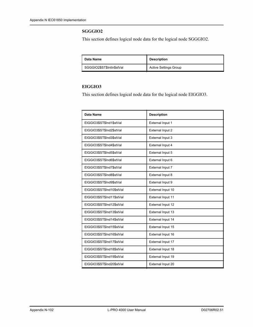
Appendix N IEC61850 Implementation
Appendix N-102 L-PRO 4000 User Manual D02706R02.51
SGGGIO2
This section defines logical node data for the logical node SGGGIO2.
EIGGIO3
This section defines logical node data for the logical node EIGGIO3.
Data Name Description
SGGGIO2$ST$IntIn$stVal Active Settings Group
Data Name Description
EIGGIO3$ST$Ind1$stVal External Input 1
EIGGIO3$ST$Ind2$stVal External Input 2
EIGGIO3$ST$Ind3$stVal External Input 3
EIGGIO3$ST$Ind4$stVal External Input 4
EIGGIO3$ST$Ind5$stVal External Input 5
EIGGIO3$ST$Ind6$stVal External Input 6
EIGGIO3$ST$Ind7$stVal External Input 7
EIGGIO3$ST$Ind8$stVal External Input 8
EIGGIO3$ST$Ind9$stVal External Input 9
EIGGIO3$ST$Ind10$stVal External Input 10
EIGGIO3$ST$Ind11$stVal External Input 11
EIGGIO3$ST$Ind12$stVal External Input 12
EIGGIO3$ST$Ind13$stVal External Input 13
EIGGIO3$ST$Ind14$stVal External Input 14
EIGGIO3$ST$Ind15$stVal External Input 15
EIGGIO3$ST$Ind16$stVal External Input 16
EIGGIO3$ST$Ind17$stVal External Input 17
EIGGIO3$ST$Ind18$stVal External Input 18
EIGGIO3$ST$Ind19$stVal External Input 19
EIGGIO3$ST$Ind20$stVal External Input 20
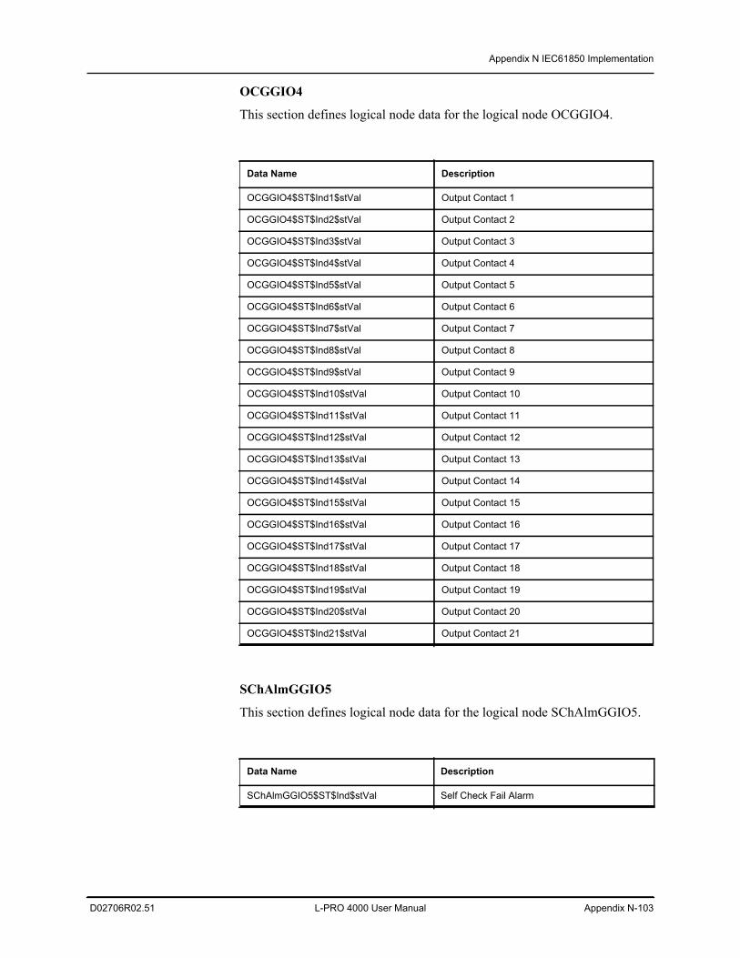
Appendix N IEC61850 Implementation
D02706R02.51 L-PRO 4000 User Manual Appendix N-103
OCGGIO4
This section defines logical node data for the logical node OCGGIO4.
SChAlmGGIO5
This section defines logical node data for the logical node SChAlmGGIO5.
Data Name Description
OCGGIO4$ST$Ind1$stVal Output Contact 1
OCGGIO4$ST$Ind2$stVal Output Contact 2
OCGGIO4$ST$Ind3$stVal Output Contact 3
OCGGIO4$ST$Ind4$stVal Output Contact 4
OCGGIO4$ST$Ind5$stVal Output Contact 5
OCGGIO4$ST$Ind6$stVal Output Contact 6
OCGGIO4$ST$Ind7$stVal Output Contact 7
OCGGIO4$ST$Ind8$stVal Output Contact 8
OCGGIO4$ST$Ind9$stVal Output Contact 9
OCGGIO4$ST$Ind10$stVal Output Contact 10
OCGGIO4$ST$Ind11$stVal Output Contact 11
OCGGIO4$ST$Ind12$stVal Output Contact 12
OCGGIO4$ST$Ind13$stVal Output Contact 13
OCGGIO4$ST$Ind14$stVal Output Contact 14
OCGGIO4$ST$Ind15$stVal Output Contact 15
OCGGIO4$ST$Ind16$stVal Output Contact 16
OCGGIO4$ST$Ind17$stVal Output Contact 17
OCGGIO4$ST$Ind18$stVal Output Contact 18
OCGGIO4$ST$Ind19$stVal Output Contact 19
OCGGIO4$ST$Ind20$stVal Output Contact 20
OCGGIO4$ST$Ind21$stVal Output Contact 21
Data Name Description
SChAlmGGIO5$ST$Ind$stVal Self Check Fail Alarm
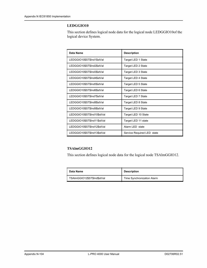
Appendix N IEC61850 Implementation
Appendix N-104 L-PRO 4000 User Manual D02706R02.51
LEDGGIO10
This section defines logical node data for the logical node LEDGGIO10of the logical device System.
TSAlmGGIO12
This section defines logical node data for the logical node TSAlmGGIO12.
Data Name Description
LEDGGIO10$ST$Ind1$stVal Target LED 1 State
LEDGGIO10$ST$Ind2$stVal Target LED 2 State
LEDGGIO10$ST$Ind3$stVal Target LED 3 State
LEDGGIO10$ST$Ind4$stVal Target LED 4 State
LEDGGIO10$ST$Ind5$stVal Target LED 5 State
LEDGGIO10$ST$Ind6$stVal Target LED 6 State
LEDGGIO10$ST$Ind7$stVal Target LED 7 State
LEDGGIO10$ST$Ind8$stVal Target LED 8 State
LEDGGIO10$ST$Ind9$stVal Target LED 9 State
LEDGGIO10$ST$Ind10$stVal Target LED 10 State
LEDGGIO10$ST$Ind11$stVal Target LED 11 state
LEDGGIO10$ST$Ind12$stVal Alarm LED state
LEDGGIO10$ST$Ind13$stVal Service Required LED state
Data Name Description
TSAlmGGIO12$ST$Ind$stVal Time Synchronization Alarm
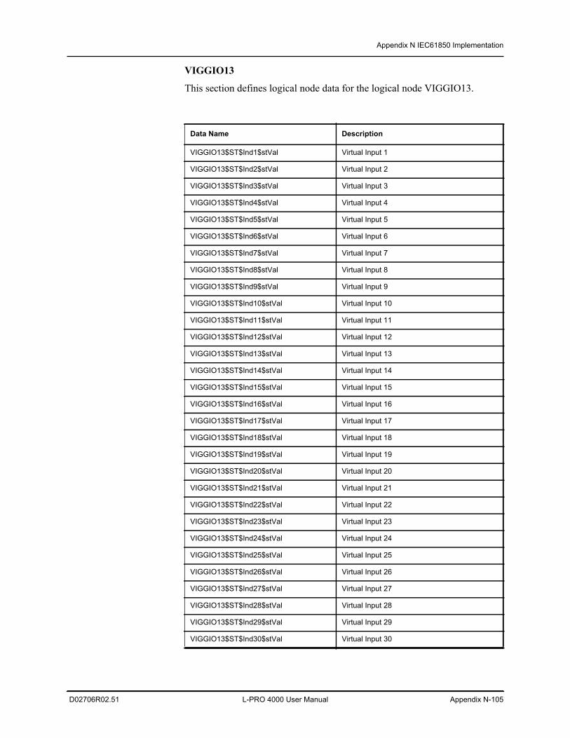
Appendix N IEC61850 Implementation
D02706R02.51 L-PRO 4000 User Manual Appendix N-105
VIGGIO13
This section defines logical node data for the logical node VIGGIO13.
Data Name Description
VIGGIO13$ST$Ind1$stVal Virtual Input 1
VIGGIO13$ST$Ind2$stVal Virtual Input 2
VIGGIO13$ST$Ind3$stVal Virtual Input 3
VIGGIO13$ST$Ind4$stVal Virtual Input 4
VIGGIO13$ST$Ind5$stVal Virtual Input 5
VIGGIO13$ST$Ind6$stVal Virtual Input 6
VIGGIO13$ST$Ind7$stVal Virtual Input 7
VIGGIO13$ST$Ind8$stVal Virtual Input 8
VIGGIO13$ST$Ind9$stVal Virtual Input 9
VIGGIO13$ST$Ind10$stVal Virtual Input 10
VIGGIO13$ST$Ind11$stVal Virtual Input 11
VIGGIO13$ST$Ind12$stVal Virtual Input 12
VIGGIO13$ST$Ind13$stVal Virtual Input 13
VIGGIO13$ST$Ind14$stVal Virtual Input 14
VIGGIO13$ST$Ind15$stVal Virtual Input 15
VIGGIO13$ST$Ind16$stVal Virtual Input 16
VIGGIO13$ST$Ind17$stVal Virtual Input 17
VIGGIO13$ST$Ind18$stVal Virtual Input 18
VIGGIO13$ST$Ind19$stVal Virtual Input 19
VIGGIO13$ST$Ind20$stVal Virtual Input 20
VIGGIO13$ST$Ind21$stVal Virtual Input 21
VIGGIO13$ST$Ind22$stVal Virtual Input 22
VIGGIO13$ST$Ind23$stVal Virtual Input 23
VIGGIO13$ST$Ind24$stVal Virtual Input 24
VIGGIO13$ST$Ind25$stVal Virtual Input 25
VIGGIO13$ST$Ind26$stVal Virtual Input 26
VIGGIO13$ST$Ind27$stVal Virtual Input 27
VIGGIO13$ST$Ind28$stVal Virtual Input 28
VIGGIO13$ST$Ind29$stVal Virtual Input 29
VIGGIO13$ST$Ind30$stVal Virtual Input 30
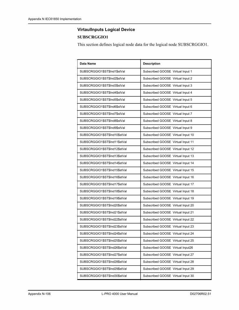
Appendix N IEC61850 Implementation
Appendix N-106 L-PRO 4000 User Manual D02706R02.51
VirtaulInputs Logical Device SUBSCRGGIO1
This section defines logical node data for the logical node SUBSCRGGIO1.
Data Name Description
SUBSCRGGIO1$ST$Ind1$stVal Subscribed GOOSE Virtual Input 1
SUBSCRGGIO1$ST$Ind2$stVal Subscribed GOOSE Virtual Input 2
SUBSCRGGIO1$ST$Ind3$stVal Subscribed GOOSE Virtual Input 3
SUBSCRGGIO1$ST$Ind4$stVal Subscribed GOOSE Virtual Input 4
SUBSCRGGIO1$ST$Ind5$stVal Subscribed GOOSE Virtual Input 5
SUBSCRGGIO1$ST$Ind6$stVal Subscribed GOOSE Virtual Input 6
SUBSCRGGIO1$ST$Ind7$stVal Subscribed GOOSE Virtual Input 7
SUBSCRGGIO1$ST$Ind8$stVal Subscribed GOOSE Virtual Input 8
SUBSCRGGIO1$ST$Ind9$stVal Subscribed GOOSE Virtual Input 9
SUBSCRGGIO1$ST$Ind10$stVal Subscribed GOOSE Virtual Input 10
SUBSCRGGIO1$ST$Ind11$stVal Subscribed GOOSE Virtual Input 11
SUBSCRGGIO1$ST$Ind12$stVal Subscribed GOOSE Virtual Input 12
SUBSCRGGIO1$ST$Ind13$stVal Subscribed GOOSE Virtual Input 13
SUBSCRGGIO1$ST$Ind14$stVal Subscribed GOOSE Virtual Input 14
SUBSCRGGIO1$ST$Ind15$stVal Subscribed GOOSE Virtual Input 15
SUBSCRGGIO1$ST$Ind16$stVal Subscribed GOOSE Virtual Input 16
SUBSCRGGIO1$ST$Ind17$stVal Subscribed GOOSE Virtual Input 17
SUBSCRGGIO1$ST$Ind18$stVal Subscribed GOOSE Virtual Input 18
SUBSCRGGIO1$ST$Ind19$stVal Subscribed GOOSE Virtual Input 19
SUBSCRGGIO1$ST$Ind20$stVal Subscribed GOOSE Virtual Input 20
SUBSCRGGIO1$ST$Ind21$stVal Subscribed GOOSE Virtual Input 21
SUBSCRGGIO1$ST$Ind22$stVal Subscribed GOOSE Virtual Input 22
SUBSCRGGIO1$ST$Ind23$stVal Subscribed GOOSE Virtual Input 23
SUBSCRGGIO1$ST$Ind24$stVal Subscribed GOOSE Virtual Input 24
SUBSCRGGIO1$ST$Ind25$stVal Subscribed GOOSE Virtual Input 25
SUBSCRGGIO1$ST$Ind26$stVal Subscribed GOOSE Virtual Input26
SUBSCRGGIO1$ST$Ind27$stVal Subscribed GOOSE Virtual Input 27
SUBSCRGGIO1$ST$Ind28$stVal Subscribed GOOSE Virtual Input 28
SUBSCRGGIO1$ST$Ind29$stVal Subscribed GOOSE Virtual Input 29
SUBSCRGGIO1$ST$Ind30$stVal Subscribed GOOSE Virtual Input 30
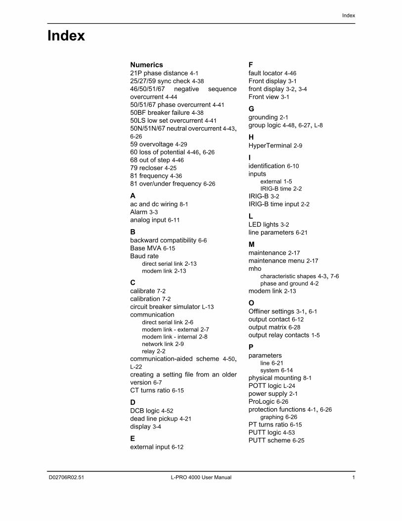
Index
D02706R02.51 L-PRO 4000 User Manual 1
Index
Numerics21P phase distance 4-125/27/59 sync check 4-3846/50/51/67 negative sequenceovercurrent 4-4450/51/67 phase overcurrent 4-4150BF breaker failure 4-3850LS low set overcurrent 4-4150N/51N/67 neutral overcurrent 4-43,6-2659 overvoltage 4-2960 loss of potential 4-46, 6-2668 out of step 4-4679 recloser 4-2581 frequency 4-3681 over/under frequency 6-26
Aac and dc wiring 8-1Alarm 3-3analog input 6-11
Bbackward compatibility 6-6Base MVA 6-15Baud rate
direct serial link 2-13modem link 2-13
Ccalibrate 7-2calibration 7-2circuit breaker simulator L-13communication
direct serial link 2-6modem link - external 2-7modem link - internal 2-8network link 2-9relay 2-2
communication-aided scheme 4-50,L-22creating a setting file from an olderversion 6-7CT turns ratio 6-15
DDCB logic 4-52dead line pickup 4-21display 3-4
Eexternal input 6-12
Ffault locator 4-46Front display 3-1front display 3-2, 3-4Front view 3-1
Ggrounding 2-1group logic 4-48, 6-27, L-8
HHyperTerminal 2-9
Iidentification 6-10inputs
external 1-5IRIG-B time 2-2
IRIG-B 3-2IRIG-B time input 2-2
LLED lights 3-2line parameters 6-21
Mmaintenance 2-17maintenance menu 2-17mho
characteristic shapes 4-3, 7-6phase and ground 4-2
modem link 2-13
OOffliner settings 3-1, 6-1output contact 6-12output matrix 6-28output relay contacts 1-5
Pparameters
line 6-21system 6-14
physical mounting 8-1POTT logic L-24power supply 2-1ProLogic 6-26protection functions 4-1, 6-26
graphing 6-26PT turns ratio 6-15PUTT logic 4-53PUTT scheme 6-25
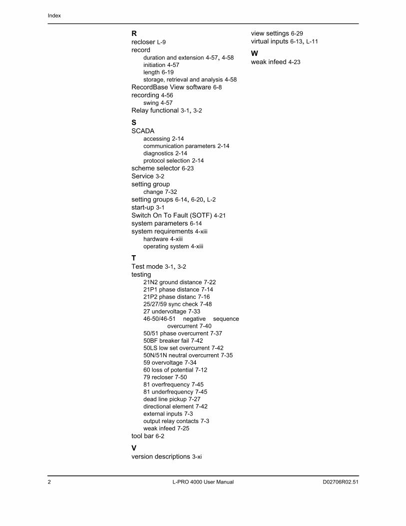
Index
2 L-PRO 4000 User Manual D02706R02.51
Rrecloser L-9record
duration and extension 4-57, 4-58initiation 4-57length 6-19storage, retrieval and analysis 4-58
RecordBase View software 6-8recording 4-56
swing 4-57Relay functional 3-1, 3-2
SSCADA
accessing 2-14communication parameters 2-14diagnostics 2-14protocol selection 2-14
scheme selector 6-23Service 3-2setting group
change 7-32setting groups 6-14, 6-20, L-2start-up 3-1Switch On To Fault (SOTF) 4-21system parameters 6-14system requirements 4-xiii
hardware 4-xiiioperating system 4-xiii
TTest mode 3-1, 3-2testing
21N2 ground distance 7-2221P1 phase distance 7-1421P2 phase distanc 7-1625/27/59 sync check 7-4827 undervoltage 7-3346-50/46-51 negative sequence
overcurrent 7-4050/51 phase overcurrent 7-3750BF breaker fail 7-4250LS low set overcurrent 7-4250N/51N neutral overcurrent 7-3559 overvoltage 7-3460 loss of potential 7-1279 recloser 7-5081 overfrequency 7-4581 underfrequency 7-45dead line pickup 7-27directional element 7-42external inputs 7-3output relay contacts 7-3weak infeed 7-25
tool bar 6-2
Vversion descriptions 3-xi
view settings 6-29virtual inputs 6-13, L-11
Wweak infeed 4-23