l i - nasa · l i i i n76.28281 assurance of ... from the retainers as required by the ball...
TRANSCRIPT

l II i
N76.28281
ASSURANCE OF LUBRICANT SUPPLY IN WET-LUBRICATED
SPACE BEARINGSI
By Frank A. Glassow
Hughes Aircraft Company
ABSTRACT
Recent research and development have made available two signifi-cantly new and different techniques for providing greater assurance ofample lubricant supply for bearings in despin assemblies and momentumwheels. Conventional lubricationtechniques appear to be satisfactory,butrigorous proof of meeting a ten-year liferequirement is lacking. One newapproach provides additional lubricant only when commar.Jed from groundcontrol, while the other passively augments lubrication at all times. Eachtechnique has specific advantages, and selectien should be related to the
, application to obtain optimum performance.
INTRODUCTION _
Early satellites were spin-stabilized and contained no moving parts,but advancing technology soon dispelled this state of simplistic bliss. Nowwe find that virtually all satellites contain critical applications of wet ordry lubricated ball bearings that are essential to meeting basic missionrequirements. A modern satellite, by actual count, has as many as 52 ballbearinss, many of which are in single-string failure locations with regardto mission performance. Some of the most important applications involveoil-lubricated ball bearings in the despin assemblies of dual-spinsatellltes or oxl and grease lubricated bearings in momentum wheels ofbody-stabilized satellites. Unlike some ball bearing applications, despinand wheel bearings must rotate continuously for the life of the satellite,which is commonly expected to be as much as I0 years. In spite of rela-tivel y outstanding success in space, stringent life and performance re-quirements have aroused cause for concern and a desire for greaterassurance of lubricant supply for these critical ball bearings.
Two techniques have been developed by the Hughes Aircraft Companyfor providing greater assurance of lubricant supply. Each technique, oneactive and one passive, is being applied to a flight program and has under-gone extensive trade studies, qualification te|ting and life testing.
' 90 JPL Technical Memorandum $3-777
1976021184-097
https://ntrs.nasa.gov/search.jsp?R=19760021193 2018-07-08T07:09:35+00:00Z

CONVENTIONAL LUBRICATION TECHNIQUES
Despin Bearings
Ball bearings employed in despin assemblies generally have boresizes ranging from 60 to 150 millimeters and operate in the range of 5 to100 rpm. They are usually lubricated with a hydrocarbon oil impregnatedinto porous cotton-phenolic ball retainers. Oil is fed by capillary actionfrom the retainers as required by the ball bearings to maintain an equili-brium thin film of oil on the balls and races. Oil may also be containedin reservoirs of impregnated porous material located adjacent to theball bearings (Ref. 1). Tests and measurements indicate that the value ofreservoirs is dubious, and they are usually regarded as sources of oilwhich may escape th_:ough labyrinth seals of the assembly rather than asource of lubricant replenishment for the bearings. Since bearings areusually warmer than adjacent reservoirs, vapor and surface transport ofoil tend to be away from the bearings.
Since despin bearings run at low speeds, a rather viscous oil andlight preloads are preferred to ensure lubrication in the elastohydrody-namic regime. Lubricant life and life of the bearings are expended in threestages (initial film, equilibrium film, and boundary), the duration of whichis determined as indicated in Table 1. Accordingly, ti_e lif_. profile of oil
film thickness in Intelsat IV or IVA bearings is depicted graphically in , ,,,Figure 1. This analysis indicates that there is ample margin to achieve
the design life of 10 years in orbit. _ :
Life of despin bearings in orbit is demonstrated by Intelsat IVsatellites, the first of which has operated successfully for over five years.Three more vehicles of this series have demonstrated nearly four yearseach of continuous operation at approximately 50 rpm {Ref. _). Hughes
_. also has a complete despin assembly with 150 millimeter bore bearingsthat has operated in a chamber at high vacuum for five and one-half 7ears.
SPL Technical Memorandum 33-777 91
1976021184-098

Table I. Lubricant/bearing lifedetermination for IntelsatIVAdespin bearings
STAGE DESCRIPTION BASIS FOR TIME DURATION TIMEYEAR,,
Reduction of initial IntelsatIV historical
I oilfilm to equili- data. 2-4brium oil film.
Gradual reduction o Loss of oilthrough2 of oilfilm from evaporation/migra- I0
initiationof equi- tiondue to tempera-librium film. ture differential.
o TACSAT historicaldata.
o Bearing and lubricantcharacteristic s.
Progression of o Composite roughness3 metallic wear in of balls and races. 0.5
boundary lubri-cation regime o Lubricant character°after loss of EHD istics. -"film (Ref.2).
o Calculation based onempirical data.
Wheel Bearings
Sizes of ball bearings used in momentum wheels vary according tothe angular momentum of the wheel, but a large range of momentum isachieved by several wheel manufacturers with 12 millimeter bore bearingssupporting the wheel. A typical bearing arrangement consists of two pairsof angular contact bearings mounted in face to face configurations withinindividual labyrinth sealed cartridges. The cartridges are spaced on acommon shaft to provide a wheel base (Ref. 4). Another arrangementemploys a single pair of angular contact bearings with precision spacersbetween the clamped races in a back to back configuration, thereby pro-viding the wheel base.
Momentum wheels supported on ball bearings usually operate in aspeed range of 3,000 to 4,000 rpm, but speeds within the range of I, 000to 6,000 rpm have been used. This range of speeds, combined with com-monly used lubricants, preloads, and ball and race finishes, ensureselastohydrodynamic lubrication provided the oil film is adequately main-talned by the lubrication systerr_.
' ' 92 3PL Technical Memorandum 33-777=
1976021184-099

In a manner similar to that used for despin bearings, cotton-phenolicball retainers are impregnated with oil to supply part of the lubrication. Sincethe amount of this oil is only one to three milligrams per bearing retainer, itis not regarded as the primary lubricant source. Additional oil may enterthe ball-race interface region by bleeding out of grease adhering to thebearing rings, or it may migrate from po,'ous oil-impregnated reservoirsor grease-filled reservoirs suitably located within the bearing enclosure.
Since the ball retainer provides a minor contribution to the lubrica-tion life in wheel bearings and the mechanism by which oil is resupplied tothe balls and races is varied and ill-defined, life expectancy is basedlargely on performance history. Successful operation in orbit is known tohave occurred for five to six years, and similar continuous operatingperiods have been achieved with wheels operating in vacuum life tests.
NEW TECHNIQUES FOR ASSURANCE OF LUBRICANT SUPPLY
Life demonstrations for both despin and w_,eel bearings are impress-ive and, when coupled with analytical techniques, provide high cov_fidenceof satisfying a 10-year requirement. Analytical methods for predicting lifeof despin bearings are probably somewhat more established than thoseapplicable to wheel bearings because of the avsilability of fairly extensivedata on torque, temperatures and performar_ce from sateUites in orbit.These data, derived especially from TACSAT and Intelsat IV _ateUites,build confidence that the despin lubricant systems can last for more tha_ten years. Nevertheless, the desire always exists to increase the marginor to back up the system with an alternate. Toward this end, Hughes hasdeveloped two lubrication techniques that provide basically differentapproaches to augmenting the lubricant supply for greater assurance oflong bearing life.
Relubrication by Command
The specifications for the Intelsat IVA and Comstar I satellites re-quired that the despin be_iing _.ssembly include a feature that would permitadding oil to the bearings on command from ground control. Prior to
: contract award Hughes had applied research to this subject, had developeda work.ing engineering model of a commandable oiler and had confirmed its _
performance. The oiler was applied directly to the Intelsat IVA and Corn-
star I satellites following optimization of size, weight and power consump-tion.
@
Before selecting the relubrica_ion approach, numerous ideas werecollected, evaluated and finally narrowed to three models for experimentaldemonstration. One approach had no moving parts, consisting of anannular metal cartridge which contained porous material impregnated withoil and a heater to cause the oil to evaporate. This device was mounted "immediately adjacent to a bearing and was found to transfer oil by evapora-tive means. The approach was dropped because of high power consumption
JPL Technical Memorandum 33-777 9_
1976021184-I00

#
and poor efficiency; i. e., only about 35 percent of the oil given up by thecartridge reached the bearing. The method also suffered from inde.'initecontrol of quantity of oil transferred. The other two methods were bothpositive displacement typet; which delivered incremental quantities of oilwith each stroke of a solenoid. Both of these approaches incorporatedfeatures to cope with cavit_tion or vapor lock,which occurred on an earlierfeasibility model. This problerr was solved in one version by employing asealed bellows, the ol_ly outlet of which was a port normally closed by acheck valve. The bellows was completely filled with degassed oil. Opera- , :tion of the solenoid would cause a ratcheting mechanism to compress thebellows an incremental amount causing the check valve to open momentarily,allowing oil to pass through a duct to the b,_,_ring. This version of asolenoid-actuated oiler was abandoned for the following reasons:
o The bellows absorbed some of the impulse of the solenoidstroke, resulting in a low pressure for injecting oil intothe bearing.
o The ratchet mechanism had wearing surfaces which re-
quired dry lubrication.
o The increment of oil ejected per stroke of the sc _oidwas larger than desired.
The selected oilcr approach has a reservoir of oil contained in achamber which includes a small cylinder. A pigton, integral with the
solenoid plunger, engages the cylinder when the solenoid is stroked. Sincethe moving plunger of the solenoid is contained within the oil chamber, the ,_single moving part of the oiler is well lubricated. A quantity of oil equalto the volume of the cylinder (less leakage) is ejected from the oiler througha ball check valve at each stroke of the solenoid, thereby transferring oilin small kna_vn amounts. The oilers are oriented on the spinning bearinghousing 8o that centrifugal force feeds oil from the chamber into thecylinder at all times. A breathing port on the oiler allows the escape ofair from the interior of the oiler as the satellite enters the vacuum of
8pace, but the port incorporates a series of fine-mesh 8creerts which pre-
vent the loss of oil _ring adverse orientation tn earth's gravity. Theoiler appears in cross-section in Figure 2, which illustrates the featuresdescribed above. Table Z provides design parameter8 of the oiler.
-_' 74 ® JPL Technical Memorandum 33-777 ;
Q
1976021184-101

Table Z. Oiler functional parameters
Solenoid:
Stroke .317 inch
Coil Resistance 17.3 ohms '; ,
Excitation 30. 5 volts
Current 1.76 amps ::
Power 54 watts :_
Time to Stroke 90 milliseconds
Oil System: '-
Oil Supply 6.0 grams
Oil Pumped Per Stroke 45 milligrams _
, Strokes to Empty 130 :
i Check Valve Opens 15 - 20 psig
i General:Weight O. 85 pound
Diameter Z.25 inches
Length 2.78 inches
In the Intelsat IVA satellite, the coils of the two oilers are conn, :ted
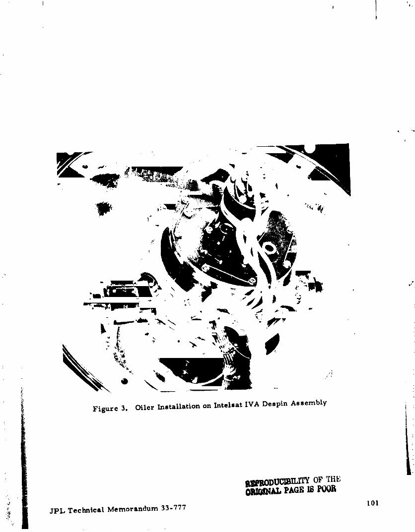
to simple pulsing circuits identical to the type used for commanding att.rude control jets. When the despin bearing assembly is built, ducts madeof 1/16 inch stal nless steel tubing are installed into the housing to carryoii from the mounting surfaces of the oilers to the forward and aft b ;arings,respectively. Oii leaves the formed end of either duct with a velocity anddirection which cause it to deposit directly onto the outer raceways of the
bearings. Since the bearing is rotating at about 50 rpm, the balls immedi-ateiy pick up the new oil and distribute it throughout the bearing. Figure 3
:: illustrates the mounting of oilers on the Intelsat IVA despin assembly.Each oiler is separately commandable so that either bearing may be reoiled
• independently.
Since Intelsat IVA satellites are in geosynchronous orbit, every sixmonths an eclipse season is encountered. During several days at theheight of each season, the temperature at the despin bearings changes
3PL Technical Memorandum 33°777 95
1976021184-102

about 15°F within a 24-hour period. Telemetry data on despin torque andbearing temperatures provide the inputs needed to calculate the oil filmthickness in the bearings, and this result provides operators with an inputfor determining use of the oilers. (Ref. 3) Figure 4 is the torque-temper-ature profile of the F-4 satellite of the Intelsat IV series on 19 March 1972.These data indicated an oil film thickness of 500 microinches (earlystage 1), which is sufficient to preclude use of oilers had they existed onthe Intelsat IV. By March of 1975 the change in torque due to eclipse hadreduced to much smaller values, indicating the initiation of stage 2. Simi-lar conditions have occurred on other Intelsat IV satellites, indicating thatthey are following the classical lubrication profile.
Pas sire Relubric ation
The cotton-phenolic ball retainer impregnated with oil has been astandard feature in wet-lubricated space bearings for many years. One ofits shortcomings is the relatively small amount of retained oil rangingfrom about one to five percent by weight, a small fraction of which willactually fee<: to the bearing. This situation prompted Hughes to develop aball retainer with much greater oil retention over the period 1971 to 1974.The result was the foam (nitrile acrylic copolymer) retainer illustrated inFigure 5 (Ref. 5). Retainers are illustrated with bearings having bore _sizes of 60 and 12 millimeters, typical for despin bearings and momentumwheels, respectively. Foam retainers contain from 10 t_ 100 times moreoil than cotton-phenolic retainers, and because of the small size of thecapillaries which connect the numerous reser, oirs within the foam cellular
structure, the oil is metered to the bearing at a controlled rate to main-; tain the oil film. Thus, the foam retainer constitutes a passive oil replen- ,_
ishment technique with far greater capacity than the conventional approach.
The foam retainer has been applied to bearings having bore sizes of150, 90, 80, 60, 12 and 6 millimeters. Vacuum life tests are presentlyrunning on four each of 60 and 12 millimeter bearings. The former, Ltypical despin bearings, have been operating at 100 rpm for three and one-half years, and the latter, typical momentum wheel bearings, have been ::operating at 5, 000 rpm for one year.
Because the capillaries in foam retainers average about 10 micronsin diameter_ they maintain a calculated 90 microinch thick film of oilon balls and races versus 20 microinches for cotton-phenolic retainers. _;This thicker film insures ample oil for elastohydrodynamic lubrication,
_: but it also produces a higher oil churning torque. Consequently, despinbearings with foam retainers run at about a 20 percent higher torque than
• with cotton-phenolic retainers after equilibrium film has been established.The duration of stage I for despin bearings with foam retainers is corn- , :parable to that for bearings with cotton-phenolic retainers, but duration ofstage 2 is calculated to be 122 years.
Figure 6 illustrates two momentum wheel fixtures, each containing : :four 12 millimeter bearings. One employs the baseline lubrication iapproach with cotton-phenolic retainers_ while the other has foam re- i
tainers. As with despin bearingse the foam retainers maintain a higher i; equilibrium film of oll on the bearing metal than is the case with cotton-
_ 96 JPL Technical Memorandum 33-777
1976021184-103

phenolic retainers. This causes a more severe running torque penalty,1.1 ounce-inches versus 0.5 ounce-inch, because of the much higheroperating speed. Continuation of 1,re testing is required to provide dataleading to possible application of foam retainers to wheel bearings.
The extensive life testing and excellent performance of foam re-tainerq in despin bearings has resulted in their adoption for the despinassembly of the Pioneer Venus satellite.
CONCLUSION
The two lubricant augmentation approaches provide totally differentsolutions to satisfy the desire for greater lubrication assurance of wet-lubricated space bearings. Each has been adopted for flight, one alreadyin orbit and one scheduled on a flight program. Table 3 shows an attempt tocompare the relative advantages and disadvantages of the two techniques.This evaluation reveals that a clear-cut overall advantage does not exi$tfor either approach, but rather that the choice should be made with relationto specific requirements of each application.
Table 3. Comparison of Oil Augmentation Techniques
ACTIVE REPLENISHMENT PASSIVE REPLENISHMENT
COMMANDABLE OILEI% FOAM RETAINER ,
ADVANTAGES
1. Preserves flight-proven 1. No added weight orball retainer, volume.
Z. Augmented oil supply Z, Oil replenishment isreserved for emergency, automatic.
!_ 3. R.eplenishment by con- 3. Failure modes are_ scious command allows virtually non- existent. __i thinner oil films, less i
torque.
DISADVANTAGES ]
I. Weight and volume I, Departure from flight-penalty, proven ball retainer.
2. Command channel(s) Z, Viscous friction torquerequired, is higher.
3. Failure modes exist. 3. Thick oil films can cause
more torque variation.
3PL Technical Memorandum 33-777 97
1976021184-104

REFERENCES
I. Glassow, F. A., "Despin Bearing Technology and Applications forCommunications Satellites,' Paper No. 70-459, AIAA 3rd Communi-
cations Satellite Systems Conference, Los Angeles, CA,April 6 - 8, 1970.
2. "New Bearings Meet the Challenge of Speed, Load and Temperature",
Product Engineering, August 1973, pp. Pl- Z5.
3. Glassow, F. A., Hofmann, G., "Intelsat IV Despin Lubrication Per-
formance, " AIAA/CASI 6th Communications Satellite Systems
Conference, Montreal, Canada, April 5-8, 1976.
4. Davis, P., Sutter, C., Reistad, K., "A Versatile New ReactionWheel Used on Fleet Sat Corn and Canadian CTS, " IEEE El,..ctronics
and Aerospace Systems Conference, Washington, D. C.,October 7 - 9, 1974.
5. Christy, R. I., "Evaluation of A Nitrile-Acrylic Copolymer As A
Ball Bearing Retainer Material, " Paper No. 74AM-SA-I, ASLF, Z9th
Annual Meeting, Cleveland, Ohio, April Z8 - May Z, 1974.
'_ This paper is based, in part, on work performed under the} sponsorship of the International Telecommunications Satellite Consortium
(Intelsat). Any views expressed are not necessarily those of Intelsat.
i, 98 3PL Technical Memorandum 33-777
r ":_.-_._ p minima .......... I IIJIl_ . • Ill . . Jim_'''_
1976021184-105

400
(,, u_ STAGE 3 -7!!i _ e
o 200
< _ 0 t•_ u. 10 12 14
_" 100 i
- STAGE 2LL
O 00 2 4 6 8 10 12 14 16
TIME, YEARS
FIGURE 1. LIFE PROFILE OF OIL FILM THICKNESS IN DESPIN BEARINGS
8O
_ 7o_._' u) 0.3
_ DESPIN TORQUE 60 1
w-0.2
o r_|n.
,-0.1
411
0 i i i i i i i06 08 10 12 14 16 18 20 22
TIME OF DAY, HOURS
FIGURE 4. TORQUE/TEMPERATURE PROFILE OF INTELSAT IV,F-4, ON 19 MARCH 1972 DURING ECLIPSE
3PL Technical Memorandum 33-777 99
1976021184-106

INTERFACE WITH BAPTA HOUSING - ,SCREENEDVENT PORT
!
i SOLENOIDCOIL!
I!
MOVING I
CORE ' I 2.67 IN.o
t-.l_
!
OILRESERVOIR
I
OIL LINETO BEARIN(
CHECK JVALVE j
I
)2.25 IN. DIA .B--
FIGURE 2. CROSS-SECTIONOF .SOLENOID-ACTIVATEDOILER
,,;;_ 100 3PL Technical Memorandum 33-777 !i
1976021184-107
R_I_IDD_IIATYOFTHEOl_& PAQEIS FOOR
JlnL Technical Memorandum 33-777 101
1 QTF_no _1_1mA ,Ino

I
Figure 5. Foam Retainers with 60 and 12 mm Bearings
_-_ RI_RODUCIBILITY OF Tl!l._
_ 102 ORI_[NAL PAGI,]ISP(_, JPL TechnicalMemorandum 33-777
1976021184-109

uu[;
i_ ,,ira ,/ ,,'0
Figure 6, Momentum Wheel Fixtures in 5, 000 RPM Life Test
_ 3PL Technical Memorandum 33-777 REPRODUC]]3]_]_ r OF TH[__ OHIe,(NAI, P,_,_.ve _._c_ 103 .
1976021184-110