(l - icas heath.pdf · rudder stiffnesses. full-scale low stiffness pressure be ......
TRANSCRIPT

43
AEROELASTICITY IN PRACTICE
B. O. HEATH
Project Manager
English Electric Aviation, Ltd.
ABSTRACT
The paper reviews some changes of emphasis which have taken place in the
application of aeroelastic theory to high speed aircraft over the last fifteen
years.
Aircraft such as the Canberra (Fig. 1) had geometric characteristics for
which flutter calculations based on structural beam and aerodynamic strip
theory should have been sufficient, but complications are described whicharose in practice.
The shape of aircraft, such as the Lightning (Fig. 2), designed for higher
speeds at supersonic Mach numbers made the application of such concepts
dubious—even for initial calculations. For complete clearance, loading and
static aeroelastic calculations as well as flutter had to use surface theory :
the greater demands of subsequent aircraft need the use of these theoriesfrom the start.
It is apparent that the problems of aeroelasticity permit no watertight com-partments to exist in a design organization; close coordination and feedback
of experience between designers, aerodynamicists, stress, servo mechanisms
and test engineers are essential at all stages. For example, evaluation ofderivatives by flutter engineers must not be divorced from the quasi-static
values derived by the aerodynamicist.
Despite improved methods of calculation, estimation of stiffness has con-tinued to be difficult and will demand further care. It will be appreciated that
large computations based on matrix methods now form an integral part of
this process; they enable a realistic structure to be examined theoreticallyrather than an idealized representation amenable to more traditional methods.
Engineers can be released for interpretative work and for improving detaildesign which must finally make manifest the advances in overall accuracy.
There are two sections: the first deals with oscillations, the second with
loads and static aeroelasticity.
903

904 INTERNATIONAL COUNCIL AERONALTICAL SCIENCES
Fig. 1.
•
Fig. .

AEROELASTICITY IN PRACTICE 905
INTRODUCTION
This review of some aeroelastic experience does not claim to present new
concepts but is intended to illustrate how separate theories and facilities were
integrated at one aircraft firm.
No representation of the pressure of timescale is attempted but development
has been sufficiently rapid for one type to climb faster than its original design
diving speed. Consequently, a procedure which enables safety to be maintained
while its unknowns are progressively removed is far preferable to an elegant
closed solution which cannot be applied in time.
PART 1. DYNAMIC AEROELASTICITY
MODE SHAPES AND FREQUENCIES
UNSWEPT SURFACES
At the start of the period under review, structural aspect ratios were suffi-
ciently high for flexural axes and simple modal shapes in torsion and flexure
from encastered roots to be assumed for initial flutter calculations, but adjust-
ment was necessary when resonance tests were completed. Recalculation was
necessary when inclusion of body freedoms and differences in end slope caused
the effective node to approach tail-surface mass balance more closely than with
the fixed root and arbitrary modes initially assumed. The necessity to account
for such effects led to the calculation of free-free modal shapes from the best
available stiffness and mass distributions. Desk machines at first formed the
main assistance to computation and although methods due to Holzer, Stodola,
and Myklestad were simple to apply for primary modes, the necessity to sweep
these out of the iterations for the higher ones was te (lious. Matrix methods
proved simpler for computers to apply, leaving engineers free for interpretive
work, and phased naturally into the programming of large digital computers
when these became available. l'rovision of analog computers enabled a further
check: it was easy to vary the frequencies of individual branch type modes on
the simulator (initially set up for zero air speed and possibly applying a forcing
sinusoidal) to obtain a better representation of tests on the ground before trying
to reproduce those in flight.
The need for such adjustment was most apparent where nonlinear stiffness
characteristics were relevant over low amplitudes of buffeting or under the
comparatively small excitation which can be applied in resonance tests, and had
to be reproduced in linear form. In the series of resonance tests On several pro-
duction Canberra aircraft the modes not only varied from aircraft to aircraft
but also with the level of excitation applied, to the extent of complete phase
change between fin and tailplane bending in the primary antisymmetric mode.
This particular case was due to production tolerances in the all-moving surface
attachments, but such adjustments are equally applicable when extra stiffness
is provided by secondary structure or where degradations due to buckling are
involved.

906 INTERNATIONAL COUNCIL - AERONAUTICAL SCIENCES
Rapid changes of cross section seriously affected the basic stiffness data
(even though diffusion theory had been applied in strength calculations), and led
to drastic changes in mode shape, frequency, and to a missed mode on resonance
tests although it was very apparent in flight. As an aid to diagnosis, results from
strain-gaged resonance tests were employed; front an accurately defined experi-
mental mode shape, frequency, and mass distribution, the bending moment in the
resonance mode was obtained by double integration through shear force. Appli-
cation of engineers' theory of bending then directly provided a distribution of
stiffness. This was lower than estimated at the end of the armament bay where an
access panel also led to reductions of lateral stiffness which were accentuated by
a transport joint in the same region. In contrast, further forward the wing con-
straint in its chord plane gave a contribution to lateral stiffness so large as to
amount to fixity. This enabled stiffening to be optimized by the attachment of
an external doubler plate; flight tests confirmed the adequacy of the changes
(Fig. 3). The Canberra tailplane flexure frequency was lowered from 15 to 12 cps
by backlash, but on the Lightning such effects have been avoided by mounting
the tailplane on stiff spigots with roller bearings.
SWEPT SURFACES
With the introduction of lpw-aspect-ratio surfaces of high sweepback on the
Lightning, it became essential to use surface theory for stressing and this extrapo-
lated to overall aircraft modes: not only was a flexural axis untenable but the
a•curacy of elastic stiffnesses based on engineers' theory was considered unreli-
able, particularly at the root trailing edge. The first method attempted for
Mill<m11...we Ca.
PILOT Nogg
Fig. 3.

AEROELASTICITY IN PRACTICE 907
COMPARISON BETWEEN CALCULATED AND MEASURED
OVERALL AIRCRAFT MODES SYMMETRIC -NO FUEL
BRANCH MODE CALCULATION. RESONANCE TEST
Ii •.
FUSE. VERT FUSE. VERT.
22 2.1 LI.
FUSE. VERT. FUSE VERT
3.1 W. 2.6 LI.
FUSE VERT. FUSE. VERT.
Fig. 4.
strength calculations was the manual relaxation of an equivalent load network
based on spar an(l rib positions, but this proved too laborious by its slow con-vergence and was eventually replaced by matrix manipulation of deflections
with elements of stiffness based on the individual boom and panel sizes, balance
of forces providing the necessary condition for the solution (and occasionallyvice versa—i.e., com)atibility of displacements on bodies). This procedure had
the useful by-product of influence coefficients for use in static aeroelastic calcu-
lations and for modal estimation, with masses lumped to the node points.
Another method is to synthesize overall modes by Lagrangian methods from
component fixed root branch modes and body freedoms, the individual branchmodes themselves being provided by matrix calculations on the encastered wing,
fuselage, tail, etc. When compared with full-scale resonance tests (Fig. 4) good
agreement on the first three of four modes was obtained by either method, but
908 INTERNATIONAL COUNCIL — AERONAUTICAL SCIENCES
those higher modes involving branch overtones were not satisfactory : test modes
could not always be reproduced even from branch modes adjusted after resonance
tests. There were several possible reasons for this structural damping of the
fuselage was demonstrably high: tail modes could not be easily excited by
wing excitation or vice versa, either on test or on the simulator, and this, com-
bined with close frequency coincidence of wing and body torsion, wing overture
bending and tailplane bending was believed largely responsible for the difficulty.
Fortunately, the fuselage modes are little affected by airspeed and the flexibility
of the branch method has enabled flight coverage to be given. (In this connection,
a direct solution for flutter speed and mode by including complex aerodynamic
terms with the structural influence coefficients has been proposed for use where
flight modes are believed to be far removed from any zero speed mo (les in
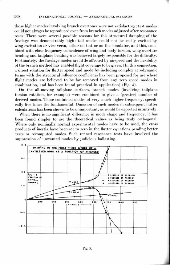
combination, and has been found practical in application) (Fig. 5).
On the all-moving tailplane surfaces, branch modes (involving tailplane
torsion rotation, for example) were combined to give a (greater) number of
derived modes. These contained modes of very 11111(.11higher frequency, specifi-
cally five times the fundamental. Omission of such modes in subsequent flutter
calculations has been shown to be unimportant, as would be expected intuitively.
When there is no signi ficant difference in mode shape and frequency, it has
been found simpler to use the theoretical values as being truly orthogonal.
Where only nominally normal experimental modes have to be used, the cross
products of inertia have been set to zero in the flutter equations pending better
tests or recomputed modes. Such refined resonance tests have involved the
suppression of unwanted modes by judicious ballasting.
0 .4
DAMPING IN THE FIRST THREE M
CANTILEVER WING A S A FUNCTION OF AIRSPEED.
0 s
• /
0.2c/ccFIACTIOM F
CIIT1C•t. I
D•oi•1140I 1.! MODE
C • I —1--
4.. MODE
— 2 0061115 OF
3 OW148 OF
4.4 0440115 OF
614 0141118 Or
1FREEDOM
felf00.1
FR1100,1FRII00/4
3.?/.10 Di
o2 0 400 600 800 1000 1200 1400 1600
V ONOTS
-0.1
— • 2
Fig. 5.

AEROKLASTICITY IN PHA( 'TICE 909
DERIVATIVES AND BALANCING
Derivatives based on two-dimensional potential flow theory had given a
reasonably adequate basis for main surface aerodynamic forces and for control
surface calculations which had provided mass-balancing criteria. Such theory
was difficult to relate to particular control surfaces with balancing by horn or
sealed beak, and became grossly misleading on control surfaces and tabs—even
if of simple form—when these were affected by shock waves and associated
boundary-layer separation. It was possible to waste considerable manpower in
evaluating second-order frequency effects on theoretical derivatives which were
incorrect to first order and often of the wrong sign compared to the quasi-static
values known from "aerodynamic- sources, i.e., derived with reference to
empirical, wind-tunnel, and flight-test results. The flutter notation differed from
that of aerodynamics and this did little to help resolve the difficulty. Because
of this emphasis, :Aerodynamics took responsibility for flutter calculations and
with more realistic derivatives the flight frequencies and airspeeds were repro-
duced by calculation. Canberra flight tests using quasi-static control applications
were used to determine the values of significant rudder derivatives and although
the degrees of freedom provided by the spring tab did not help obtain precise
answers, they were sufficient to confirm bounds of probability for the rudder
direct and aerodynamic cross stiffnesses.
In the absence at that time of a large available high-speed tunnel, full-scale
low-speed tests on a section of wing and aileron were made which, despite the low
speed, were of considerable use in providing an overall datum for the stiffness
derivatives. Detailed information on the effectiveness of the beak seal by pressure
plotting was provided by pressure plotting tand permitted rolling ('ases to be
more rigorously covered).
Briefly, for the Canberra tail surfaces at frequencies inider 8 cps, adjustment
of the direct aerodynamic control surface stiffness to avoid coincidence with main
component frequencies was effective, but represented a compromise with stability
and control considerations as is so typical: fortunately, provision for this luid
been made in the basic design of the tail surfaces where easy adjustment of the
horn balance was available and no final embarrassment ensued.
Removal of aerodynamic cross coupling was similarly effective, and forward
mass balance proved beneficial throughout in line with theory.
After a report of 24 cps oscillations on an aircraft assigned to experimental
flying, calculations showed the importance of tab direct mass inertia, tab product
of inertia about the control and tab-hinge lines, and the tab direct aerodynamic
stiffness. The variation in damping noted by the pilots in flight clearance of
production aircraft had given some correlation with variable mass characteristics
attainable within production toleranCes: this clue was exploited by adding t ab-
mass balance for flight tests ill such a manner that the mass variations quoted
traversed several computed flutter bounds at positions depending upon the tab
direct aerodynamic stiffness assumed.
Demarco t ion defined in flight bet ween sa t isfactory and unsa t isfact orydamping fixed the aerodynamic tab stiffness value which must have applied,
and this was then used in further calculations. To remove second-order effects,

910 INTERNATIONAL COUNCIL — AERONAUTICAL SCIENCES
routine balancing of main surfaces to closer limits was introduced; productionflight tests to raised levels confirmed that the cure was complete.
Higher-frequency vibrations on Canberra were in general improved by lightertab surfaces which gave lower direct inertia and increased the favorable productof inertia about the hinge lines. Taut skinning avoided increase of trailing-edgeangle under flight suctions, which had led to undesirable loss of direct aero-dynamic tab stiffness.
On the Lightning, the power controls did not entirely remove the need for massbalance; failure cases had to be covered, but even in the controls working cases,mass balance proved economic in eliminating flutter at the design stage, e.g., onthe aileron, without appealing to excessively high impedances for which weightpenalties would have occurred, and which could have intensified the task of thecontrol designer in the light of knowledge then existing.
HEORIES FOR TWO ARBITRARY MODES
(0) LINEAR TWIST MODE ex20
161411.0Rn INCIOINCI
LOAOINO
It
C.C14NULT OP• 7 t CALCULATION
-A- IP4PII C•L THIORT,K•0.• K IMAMS
10
K • 0.5K. 0.•
4•0-33
02 04 04 0111 i.0
(9 PARABOLIC TWIST is. 4.11
K• 0.50
C CLL K. 0.36
4.0
Z.0
• Pwl-T1401.1. 7K 2 CALCULATION
IMPIRIC•L 7N20121 K•0.6 K KAKi1D
o0 0 2 0•A 0.• 04 I. o
oo
6.0
Fig. (3.

AEROELASTICITY IN PRACTICE 911
TAILPLANE NORMAL MODES COMPAMSON
Of tic PART OF DAMPING L IFT DISTRIBUTION&
4.0
CCU.
3 0
OVERTONEMODE
2•0
FU AAAAA NTAL
10
/ /
• MULTHOPP- OrARNER
—0-- EMPIRICAL THEORY
oo 01. 04 0 6 12 0 I-0
Fig. 7.
Although formal lifting surface calculations became available at a later stage,interim Lightning calculations were based on what may be described as a dynamicanalogue of tichrenk's method for static spanwise loading. Examination of the
loadings derived for static aeroelasticity (Fig. 6) and available dynamic surface
loading (Fig. 7) data had shown that spanwise loadings could be synthesized
from two components—the uniform incidence load weighted by the mode shape,plus a fraction of the uniform incidence mode decided by the spanwise integral
of the first component—the latter term being a measure of spanwise induced
effects.
EFFECT OF POWER CONTROLS
The representation of power controls in the flutter equations as an impedancehaving stiffness and damping as its components has been found satisfactory.
Flutter speeds can be presented as a function of these components where they
912 INTERNATIONAL mum-IL — AERONAUTICAL SCIENCES
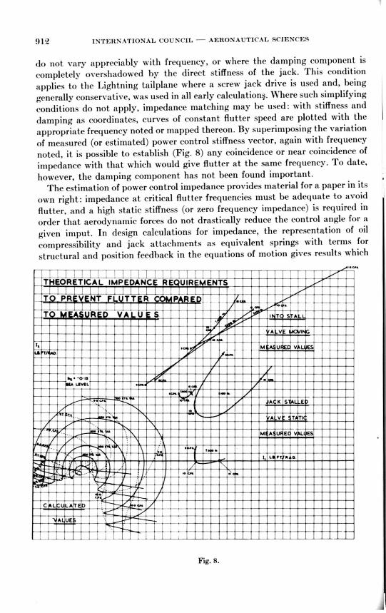
do not vary appreciably with frequency, or where the damping component is
completely overshadowed by the direct stiffness of the jack. This condition
applies to the Lightning tailplane where a screw jack drive is used and, being
generally conservative, was used in all early calculation§. Where such simplifying
conditions do not apply, impedance matching may be used: with stiffness and
damping as coordinates, curves of constant flutter speed are plotted with the
appropriate frequency noted or mapped thereon. By superimposing the variation
of measured (or estimated) power control stiffness vector, again with frequency
noted, it is possible to establish (Fig. 8) any coincidence or near coincidence of
impedance with that which would give flutter at the same frequency. To date,
however, the damping component has not been found important.
The estimation of power control impedance provides material for a paper in its
own right: impedance at critical flutter frequencies must be adequate to avoid
flutter, and a high static stiffness (or zero frequency impedance) is required in
order that aerodynamic forces do not drastically reduce the control angle for a
given imput. In design calculations for impedance, the representation of oil
compressibility and jack attachments as equivalent springs with terms for
structural and position feedback in the equations of motion gives results which
'THEORETICAL IMPEDANC RE UIR ENTS
IT 011 NT -TT-- R P —1 ---ri
. ::TO A R D VA -U—ST ' T 1---+-T
t r1--
,
•st••
•ORO
A KS E
t1-4 • -0•13;
UIVILL
-
, -,
A V T TI
MAUE V ES
- - -I L IT R D.
7
--t-- 1- -t-
t ± r •tt
_ L
Fig. 8.
- -r
r
-
S L -1-
A V
M EASURF-DTVE;-

AEROELASTICITY IN PRACTICE 913
compare favorably with the results of more comprehensive analog simulation.
To cover high-temperature cases, the bulk modulus for the oil at its maximum
operating temperature is considered.
Failure cases also need to be covered—for example, on a tandem or dual jacks,
the failure of one pressure supply. This had little effect on the Lightning aileron
which has two piston jacks with coupled inputs.
The minimum value of zero frequency impedance likely to be encountered is
when the jack is stalled by high thrusts acting on it. The control valve is then
wide open so that position feedback has no further significance; oil compressi-
bility in the system and attachment stiffness decide the impedance.
To determine the impedance by test a sinusoidally varying load is applied to
the output (its magnitude is known from strain gages on the jack body previously
calibrated in a test machine) and the phase and amplitude of the response
monitored over the relevant frequency range. Test results usually have consider-
able scatter hut generally show the analytical predictions to be adequate. As an
aircraft is not usually available as soon as its power controls, tests are carried
out initially in a rig and corrected for structural stiffness. It has been usual to
test with the input locked so that the valve lies within its overlap to give an end
point static value, with various rates of input (as in practice), and with the unit
going into stall or stalled. Rate of loading does not greatly modify the stiffness
once friction effects are passed, but phase changes are induced, and variation
between direction of stroke has been apparent. At lower frequencies and higher
force levels, phase lead has been recorded, although lag is usual.
Changes in overlap have caused little effect and tests after endurance cycling
have exhibited only small change in characteristics, mostly on the phase differ-
ences.
Overall stability and integrity are checked as part of the general aircraft
clearance. This does not fall within the scope of this paper, except to mention that
careful mass balancing of the input circuit has proved necessary in rigid body
modes, and that the most practical method of clearing that circuit dynamically
is by controlled jerk tests (using springs to provid ( the impulse) and resonance
tests, both with the circuits live. This shows up any instabilities and frequency
coincidences, but does not completely cover the effects of aerodynamics.
Duty cycles set up for proving power control integrity included the effects of
demonstration flying, and with the growing popularity of formation displays, the
effects of adjacent aircraft may have to be assessed for the loading cycle.
When electronic aids to aerodynamic damping or stiffening are installed care
must be taken to insure that the pickoffs associated with these are not sited on
structural antinodes and that the gain provided is not high enough to provide
an unstable loop through the power controls and autostabilizer system at
structural frequencies.
As the Lightning does not require such devices to provide satisfactory basic
characteristics no difficulties have persisted, but oscillation did occur during
early flying with roll rate gyros too near antinodes, and with couplings not
revealed by the simulation of the ground rigs.

914 INTERNATIONAL COUNCIL AERONAUTICAL SCIENCES
MODEL TECHNIQUES
To provide a check on the flutter characteristics of the Lightning wing, sothat skin gages could be confirmed pending the conclusion of preliminary calcu-lations, three I/7th scale wings were provisioned for free-flight rocket firing. Torespect similarity, thin light alloy surfaces had to be used and stabilized againstbuckling; a balsa filling was selected. Unfortunately, this led to considerableunwanted stiffness, which persisted despite extensive slotting on the model.(When tested, the aircraft wing itself proved stiffer over low loadings thancalculated, due to secondary structure picking up load through fastener friction,etc., although at proof and ultimate the theoretical load (listribution was in goodagreement.)
The first and second rocket models showed no divergent oscillations up to andsatisfactorily beyond the design diving Mach number of the aircraft, but hadphases of continuous vibrations at the wing fundamental bending frequency,reminiscent of buffeting. This could have been induced by the configuration ofthe rocket boosters, so a cleaner third model was built, which was used to checkroll rate and aileron reversal at the same time. Again, no divergent oscillationsoccurred, but the vibration persised at a lower amplitude. As buffeting presentsno difficulty on the Lightning—such as does exist is believed to emanate fromthe fin—rough air may have been the cause in the rocket model. No roll reversaloccurred (due to the location of the aileron on the main spar extremities thereis little twist), although a reduction of effectiveness due to bending did occur,in good agreement with theory (Fig. 9).
ROLLING ROCKET MODEL
ROLLING POWER OF AILERONS
POiHTSTI&Ittp Ort
IIIHISIT,11 TO INERT! •
CO ..... IOM
CALCUL•TION FOR
FALL Rai AIRCRAFT
-ff
MO L TO ORE ThOFOR •hLIROm MOHMTIHR
FLIV I SILIIT
\
•••
00051. WIT1400T 00011CTION
FOR •IL0000 mOuWTIOR•I hT
MACH No
Fig. 9.
AEROELASTICITY IN PRACTICE 915
The setting of the Lightning tailplane spigot out of the tailplane chord plane,
to give acceptable fairing on the fuselage, gave some concern as to dynamic
couplings which might occur such as fore and aft bending with rotation. To
explore these, a quickly constructed device capable of easy adjustment was
required. Cover over the whole Mach number range was not believed essent•lal,
as any unusual effects of the geometry would doubtless be reproducible at low
speed, given sufficiently adaptable stiffnesses. A Xylonite model was soon pro-
posed, but was subject to the criticism that no such model known at that lime
had fluttered allegedly due to the high structural damping of Xylonite or the
variation of its Young's modulus with frequency. To resolve these particular
issues a segmented model unswept wing was-constructed with a single spar.
When subjected to resonance tests, fore and aft bending occurred and obscured
the normal bending and torsion modes—even though the configuration was
completely conventional. The mass of the exciter was sufficiently great in com-
parison to the model to give difficulty, and finally a manual displacement was
found to give satisfactory vibrations of which the wave forms were recorded
optically. From their decay a structural damping coefficient of 0.08 was deduced,
confirming part of the objection.
The shear and Young's moduli were determined over a range of frequencies
and were found to increase from the static value as suspected. When this effect
was taken into account, good frequency agreement was obtained; the modal
shapes were in good agreement with calculations throughout. The flutter speed
with an added movable mass followed the variation calculated, but was higher
in actual speed than theory throughout.
A representative half-scale Xylonite model of the tailplane was constructed
for testing in the Warton low-speed tunnel, with a glass cloth spigot to reproduce
the correct ratio of stiffnesses for light alloy to steel. To pceserve scaling param-
eters, extensive lead shot loading was employed, the skin thickness then follow-
ing the speed scaling. When tested, supported from the wind tunnel roof,
the stiffness was lowered by leading-edge skin buckling, which raised the
flexure/torsion frequency ratio, and no flutter was reproduced as a result.
However, damping was low at the highest tunnel speed and in reasonable agree-
ment with flutter calculations; no unusual couplings were observed and the
aircraft was cleared for flight with greater confidence on the basis of calculations
using conventional modes. (Later calculations showed fore and aft bending coul (1be stabilizing.)
Single degree of freedom flutter, as represented by a loss of direct damping
in surface rotation, was explored by a 1_[6th scale wind-tunnel model of the
Lightning fin and rudder in the Warton transonic tunnel. The rudder was of
Tufnol and had a steel spar. It was mounted on to a dural fin by steel bars of
variable stiffness so that the frequency parameter could be changed. Negative
damping was found between Mach numbers of 0.95 and 1.'2, agreeing fairly well
with estimates.
In flight, the transonic aft movement of the rudder-induced sideload was
found more important, producing couplings with the fin bending, and a reduction
of rudder span was effective in curing this. The horn mass balance was removed

916 INTERNATIONAL COUNCIL — AERONAUTICAL SCIENCES
in the process, but this gave a much higher frequency to the torsional rudder
mode, which enabled the stiffness of the power control to be effective both in
that mode and with fin bending subsonically. Manual reversion was deleted
by using tandem jacks.
FLIGHT TEST TECHNIQUES
"BON liERS''
At low frequencies, stick jerking proved valuable on Canberra, but due to the
relatively low cut off characteristics inherent in stable power controls, generally
t hese have not proved a suitable medium (in our experience) for providing flight
excitation for flutter tests. On a high-density modern aircraft without an
armament bay, little volume exists for the installation of inertia exciters so that
the success of small explosive charges has been welcomed. These appear to be
quite adequate to cover all important modes if sited with reference to the best
data on antinodes, and have proved economic in flight testing time. The range
of instrumentation pickups and their positioning should similarly receive careful
study.
- Rotnat AIR EXCITATION”
On the Canberra the vibrations which were true flutter mostly occurred quite
early in flight development of the prototypes and were, of necessity, quickly
solved (see above) by conventional means, but not without considerable effort.
Of more lasting concern were the limited amplitude oscillations which remained
due to the low damping of the tail modes. These oscillations assumed a pure
form at high indicated speed at the fundamental 6-8 cps frequency, as Opposed to
those at high subsonic Mach number where a more ragged record involving higher
frequencies was obtained.
Such effects become most severe on production aircraft (requiring early re-
lease) in periods of good weather, but examination of Meteorological Office
records of lapse rates and the application of Richardson's and Scorer's criteria
for turbulence gave no significant correlation with flight difficulties and their
day-to-day variation.
In order to rationalize reporting, to discover and separate the dependence of
these oscillations on speed and Mach number, a systematic flight plan permuting
six indicated air speeds and five .Mach numbers was derived. Oscillograph
records at several airframe stations were taken on each flight at the twenty-odd
practical flight conditions which resulted. This was necessary as pilot opinion
couhl not represent conditions over the whole airframe, and qualitative reports
involving improvement and deterioration in different flight conditions were diffi-
cult to assess (even after the pilots' notation had been demonstrated to the
engineers concerned by flight experience!) Traces had to be analyzed manually
at that time, and this was not easy where overtone modes and ragged wave forms
obscure (l the basic 8 cps traces whose amplitude and phase relationship were
desired. After such analysis "a 3-1) plot" was necessary (Fig. 10) to show the
form of variation but still gave little assistance in diagnosis or assessment of
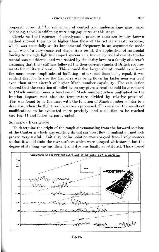
AEROELASTICITY IN PRACTICE 917
proposed cures. Ad hoe refinement of control and undercarriage gaps, massbalancing, tab-skin stiffening were stop gap cures at this stage.
Checks on the frequency of aerodynamic pressure variation by any knownmethod showed these to be higher than those of the actual aircraft response,which was essentially at its fundamental frequency in an asymmetric modewhich was of a very consistent shape. As a result, the application of sinusoidalforcing to a single lightly damped system at a frequency well above its funda-mental was considered, and was related by similarity laws to a family of aircraftassuming that their stiffness followed the then-current standard British require-ments for military aircraft. This showed that larger aircraft would experiencethe more severe amplitudes of buffeting—other conditions being equal, it wasevident that for its size the Canberra was being flown far faster near sea leveleven than other aircraft of higher Mach number capability. The calculationshowed that the variation of buffeting on any given aircraft should have reducedto (Mach number times a function of Mach number) when multiplied by thefraction (square root absolute temperature divided by relative pressure).This was found to be the case, with the function of Mach number similar to adrag rise, when the flight results were so processed. This enabled the results ofmodifications to be evaluated more precisely, and a solution to be reached(see Fig. 11 and following paragraphs).
SOURCE OF EXCITATION
To determine the origin of the rough air emanating from the forward sectionsof the Canberra which was exciting its tail surfaces, flow-visualization methodsproved very useful. Initially, iodine solution was sprayed from likely sourcesso that it would stain the rear surfaces which were sprayed with starch, but thedegree of staining was insufficient and dye was finally substituted. This showed
VARIATION OF FIN (TOP FORWARD) AMPLITUDE WITH LkS. IL MACH No.
_
—
—
lot/MATCH MACH Mt—
-
Fig. 10.

918 INTERNATIONAL COUNCIL AERONAUTICAL SCIENCES
o
3r11IA
NV31,1
01D3JJ3
AO
Ali'VNINMS
INOLLYIS
11Y
0
SNOLLY*)141001^1
STANDARD AIRCRAFT C T BUSHESSELD ACTUATOR
FN sE•LS S STIFFENEDPANELS REMOVED
ADD CLOSE TOLERANCE
BUSHES AND ACTuATOR
ADD TIP FAIRINB
SEAL FIN STUB
SEAL BULKHEADS
REMOVE FAIRIN%
REMOVE SEALS
ADD STIFFENED PANEL.
STANDARD AIRCRAFT CT BusNEsSELTP ACTUATOR
" SEALS E STIFFENED
PANELS REMOVED
ADD STRAKE
ADD SPLIT ELEVATOR
REMOVE STRAKE
Fig. 11.
that the wakes from the canopy, the wing root, and the bomb doors all followedthe upsweep of the rear fuselage to the elevators, but little could be clone tochange this. However, there was sufficient staining inside the fuselage where thetailplane center box passed through it to show that internal pressure differentialswere also acting on the flow. Suspicions that the fin and rudder shroud gaps wereopening under the actions of pressure differentials on the shroud had already ledto the installation of pressure pickups in that region. These had detected apressure variation changing in the same way with Mach number as the correctedamplitude already described. By sealing internal gaps some improvement re-sulted; external sealing strips at the tailplane root proved still more effective,but were limited by changes to longitudinal trim (which normally had a desirablenose-up change as the Mach placard was approached). There was an incidentalimprovement in snaking characteristics, due to greater effectiveness of the rudderaft of its hinge lisle in direct Mach and cross aerodynamic stiffness.

AEROELASTICITY IN PRACTICE 919
VORTEX GENERATORS
Flow-visualization studies using tufts showed (by the wear of the tufts) that
separation was occurring on the base of the fin and enabled vortex generators to
he positioned. They proved effective on the fin and were used there on several
production aircraft, but when applied to the tailplane they produced inadmis-
sible trim and stability changes and were not pursued.
RUDDER CONSTRAINT BY POWER CONTROL
Flutter calculations suggested that the 8 cps flutter speed would be raised by
fitting a stiff power control so that greater damping in the buffet modes could be
expected at the lower speeds of actual flight. When a piston-type power control
was fitted as a trial installation, 8 cps buffet was eliminated as predicted, but a
15 cps oscillation involving chiefly rudder torsion with jack-support deflection
became apparent. However, aerodynamic sealing was sufficiently effective to
STRUCTURAL RESPONSE TO HIGH
MACH NUMBER BUFFET
- FWD.
. •• • A FT.
8 C.PS. MODE-STANDARD
m.me••••••al/ ••••
FWD.
AFT.
8 CPS. MODE-CLOSE TOLERANCE BUSHES
Fig. 14.

920 INTERNATIONAL COUNCIL — AERONAUTICAL SCIENCES
reduce the level of the latter to an acceptable value and the installation hassubsequently proved satisfactory in service.
OTHER STIFFNESS CHANGES
Flutter calculations (using branch mode stiffnesses adjusted to approachmeasured primary modes and frequencies) indicated that increased tailplanebending stiffness, decreased fin bending stiffness and increased fuselage lateralbending stiffness would all be beneficial in raising the 8 cps oscillation limit speed.As described above, external stiffening plates were effective in raising the fuselagelateral frequency and making rudder-mass balance more effective so that theother less convenient methods were not necessary. Close tolerance bushes weretested on the tailplane bearings but gave such an extreme modification in modeshape that they were not finally fitted, despite generally favorable results, asthe amount of new work implied was uneconomic bearing in mind the other im-provements (Fig. 12). Similar factors weighed against the uncoupling of theelevator halves. This gave reduced 8 cps amplitudes by virtue of favorable
WATER TUNNEL FLOW VISUALISATION.
ORIGINAL 80MB BAY.
PR FLARE BAY,
ROTATING BOMB TRAY
Fig. 13.

AEROELASTICITY IN PRACTICE 921
antisymmetric elevator-half rotations induced by their horn mass balances.A buffet in a 24 cps mode which normally involved tab rotation in coincidencewith elevator torsion at high speeds was also eliminated, but frequency coinci-
dence of a control rod with a lowered high-frequency bending mode of the eleva-tor halves occurred—it could have been eliminated, but at the time was sufficient
to terminate the development.
ARMAMENT BAY BUFFETING
Adaption of the Canberra to high-speed, low-altitude roles emphasized theimportance of bomb-bay buffeting when a long bay is involved. Later flightexperience on versions with a shorter armament bay installed showed these tohave little increase in amplitude above the clean aircraft when their doors wereopened. Such results were in agreement with water and wind-tunnel work,which showed length-to-depth ratio to be a critical parameter (Fig. 13).
If critical ratios of length/depth dimensions (about 6:1) cannot be avoidedin basic design, a conventional bay may be improved by rounding the rear bulk-head, by fitting forward spoilers, by compartmenting the bays, or by augment-
ing the filling of the bay provided by the stores. Rotating doors can provide amore positive cure as demonstrated by the B - 57 version of the Canberra.
As the frequency distribution of the excitation is a wide one, stiffening is onlylikely to raise the frequency at which buffeting occurs so tha most cures rest in
the field of aerodynamics.

922 INTERNATIONAL COUNCIL — AERONAUTICAL SCIENCES
PART 2. LOADS AND STATIC AEROELASTICITY
UNSWEPT WINGS
It was necessary to make aeroelastic corrections to the Canberra spanwise wingloading distribution to cover wing twisting which occurred at the higher end of itsMach number range, where the wing center of pressure moves forward (prior toits rearwards shift as M = 1 is approached beyond the normal flight region).The nose-up wing moment was further increased on fitting tip tanks, whoseforward body lift was increased by the upwash field still existing at the tip atthe subsonic speeds involved.
These aerodynamic effects were magnified by the rearward position of thesingle main spar (forming the forward end of the torsion box) at 40 percent chordleading to an aft flexural axis. The skin gages were typical of light sheet-stringerconstruction designed to buckle about 30 percent ultimate, and it was necessaryto correct for the postbuckling loss of stiffness. Search of literature made at thetime showed a surprising lack of data on this and little evidence that it wasconsidered. No doubt the increased sheet gages (or integral construction) ofthin wings has now overtaken this shortage as far as the high-speed designer isconcerned. The stiffness of the drop-tank mounting also contributed an importantfactor in deciding the divergence speed.
SWEPT WINGS
INITIAL STAGES WITH SWEPT WINGS
Several lifting surface theories available for load calculations on the Lightningsurfaces were found sufficiently adequate to agree with (or provide) overallstability derivative calculations, after thickness correction (Fig. 14). Vortexlattice theory due to Falkner was used, extended to M = 1 by the application ofcoordinate adjustment to downwash function tables; linear theory was used at
TI A I NAERODYNAMIC CENTRE POSITIONS
6o
P0110
TION
ON
MEAN
CAOlt
D
-So
45
WING/5or5 5 N011 ri.AP
in.o/Ioor 1.• most FLAP 447'1.wIN0/000y 015051 FLAP 0.5! (ILOTTID).
FLAT.
LIT.
•
SL
0 III (itiiibmoo)
40,000.
t000'
34,000'
1A 00 0'
40 •
15
MACH NI
Fig. H.

AEROELASTICITY IN PRACTICE 9'23
OADING ON WING & CHORDW I
POSMON AT AI • 1 42
roM tmclototus or Tr1(
w LOCAL LOAD INCREMENT
I S- DYNAMIC PRESSURE
$ SIAN -SPANTIP INCIDENCE
n I N DE X 0,1,2 -5
•7 V/S
DISTANCE ERMA
AC ROOT NA6AIC SPANWIIIE
LOADING
os
fcm wow Is(
A
Fig. 15.
supersonic speeds. Aeroelastic distortions were covered by the assumption ofpower series distributions for normal deflection in terms of nondimensionalstructural span, with slopes resolved into aerodynamic incidences. Pressuredistributions for these were resolved along the spars (Fig. 15) so that virtualwork in increments of the modes assumed combined with strain-energy incre-ments provided sets of linear simultaneous equations. Solutions of these wereobtained at several speeds but ill-conditioning resulted at others. By combiningthe power modes so as to respect structural boundary conditions, this difficultywas overcome and one mode alone was finally found to predominate.
The tailplane treatment was similar, but as it is located close to the wing itcould not be assumed to be in a uniform flow field. The downwash field from thewing was expressed as a power series of terms of nondimensional tailplane spanto give the basic loading using the loads in the power series incidences.

924 INTERNATIONAL COUNCIL - AERONAUTICAL SCIENCES
On the all-moving tail surface, lack of continuous root constraint led to simpledistribution modes—no more than linear twist being necessary—and solutionwas consequently quite simple. At a later stage, a refinement was made both towing and tailplane by including the aeroelastic loading corresponding to mass-induced deflections.
To minimize hinge moments on the Lightning tailplane a swept hinge line isused, designed to pass through the range of center of pressures; any undue in-accuracy, while still apparently small in terms of chord, could be disastrous whenexpressed in terms of hinge moment. With the application of a modest tolerance,and an allowance for thickness, reliable values were obtained by the methodsdescribed. No difficulty has occurred during development and service, and wind-tunnel measurements before flight were also in good agreement.
In later work, finer networks were employed with more chordwise points, andthe M = 1 methods were refined.
LOADS, LATER STAGES OF SWEPT WINGS
By evaluating the aerodynamic influence coefficients the pressure induced atone element can be related to the slope at another. On combining these influencecoefficients with those of the structure, a solution by matrix manipulation orinteration on a digital computer becomes possible. This gives pressure differentialdistributions as a series of blocks which strictly require smoothing into the usualcontinuous representation (Fig. 16). Since the stressmen will integrate theseinto shear force and bending moment, no difficulty results by leaving them asthey are, providing overall balance of forces is respected. (Overall stressingcalculations refer loads to nodal points for local stressing anyway.)
For subsonic speeds the spacing of reference points in load calculationscaters to tip effects. For supersonic speeds the aerodynamic influence coeffi-cients are most easily evaluated where the points involved are effectively part ofan infinite surface; where tip effects are involved, modification should strictly bemade, but theory is not well in agreement with experiment in these regions, andin practice their need is doubtful, especially on the small area affected onthe Lightning. Corrections for trailing-edge effects are in reasonable agreementwith theory and were always incorporated.
Any account of loading calculations would be incomplete without mention oftwo other effects—namely, body lift, and the system of forces given giving pitch-ing moment without normal force. For the former, slender body theory was usedwith a "cross-flow friction" correction determined empirically, with terms forintake lift based on change of stream tube momentum. This proved satisfactory.
Pitching moment coefficients at zero lift remain difficult to predict; attemptsat correlating past measurements on other aircraft against factors such as theproduct of body volume times wing-setting angle (as suggested by slender - bodytheory) did not produce satisfactory results even on low-speed data. Tunnelresults were suspect, being very sensitive to inclination of flow field, as testson inverted and upright models showed. Consequently, a toleranced band hasbeen used overall, associated with an equivalent load distribution which is not

AEROELASTICITY IN PRACTICE 925
too far removed from theory in shape, with special attention to cockpit and toall body settings. The system of forces applying at zero lift will have other effectsthan longitudinally—for example, wings with camber varying appreciablyacross the span will have modified bending moments.
LATERAL CASES
The directional stability of aircraft at high incidence and/or high Machnumber is decided by the difference between a falling fin contribution and asustained destabilizing body effect (leaving ventral fins aside); consequently,the aeroelastic corrections to the fin term can become very important, and thereis some suggestion that the forebody can contribute when derivatives correctedfor aeroelasticity are fed into dynamic calculations. These calculations have tobe made at many flight conditions, for many pilot actions (using real timesimulation), and the search for critical cases — and critical instants — therein is atedious one.
SPA NWISE BLOCK LOADING DISTRIBUTION
FOR A MACH No OF I •2 AND VARYING DYNAMIC PRESSURE
RIGID 11iC
3 0 0.000'
4
36.000.
26.000.
10 000'
SEA
LEVE
r L E
0
Cr
T E
1-5
THEORETICAL
DISTRIBUTIONi0R RIGID AlC
I 0
-4 6 -a I-0
Fig. 16.

9‘26 INTERNATIONAL COUNCIL — AERONAUTICAL SCIENCES
REQUIREMENTS OF MORE RECENT PROJECTS
Performance requirements are progressively becoming more exacting and inorder to minimize weight, the more recent a project the more it must enjoy thefull flutter and aeroelastic treatment from the start.
Where flight through turbulent air provides a prime requirement, care willhave to be taken to avoid those frequencies which have been shown to be coinci-dent with the natural resonances of the human body. This necessitates the com-putation of normal modes in the early layout stages, which is not a great hardshipas weight calculations are now virtually a first stressing from which the stiff-nesses can be deduced, and for which mass distributions are needed in any case.Departures from this idealized case will have to be carefully watched during thelater stages of design in view of previous experience on cutouts, especially nowthat undercarriage retraction into the fuselage and fuselage engine installationsare so common.
To give guidance to the project engineer in choosing crew and equipmentpositions or to increase fatigue life, the response to a spectrum of turbulence can
LOW FREQUENCY SPECTRA FOR FIN ROOT
BENDING MOMENT
LB F T
(11) 11•11CTItLam w1TH10 OF
RAO/ sic
(01) SPIC,T•um wITN I Of
(FLIRIGLI FRONT • WI
FUGILARI)
(C) I•ICTRunwiTH a OF
(Ft-10(11161REAR FU $$$$$$
ONLY)
(a) Rio 0 NC a ow
(.) c p.s.
. /
'
Fig. 17.

AEROELASTICITY IN PRACTICE 927
be evaluated (Fig. 17). For example, where a tailplane of large area providesgood damping in body freedom modes, but has itself lower natural frequencies—would a smaller and stiffer tailplane be an advantage? The size of the fin is
analogous in lateral modes.The response calculations (for the configuration finally chosen) give the vibra-
tion levels which should be specified to equipment manufacturers, together with
the frequency ranges of greatest interest to the designers of antivibration mount-ings. Effects of overload stores can be accommodated, including where necessary
the elasticity of pylon mountings.By far the best method of clearing flutter and other aeroelastic problems is to
insure in the basic design that they cannot occur. One method of doing this be-comes possible with ramjet powered aircraft, where the propulsion can be inte-grated with the structure. On the wing, for example, the noncircular cells soformed provide intake ducts and give a structure so deep that its frequenciesare too high for flutter to occur. The drag is equivalent to that of a thin wingby virtue of the airflow through the ducts. If a triangulated Warren truss isformed, the effects of temperature variation are minimized.
Overall design considerations have never enabled English Electric to explorethe beneficial effects claimed for forward slung pods in the flight stage, hut thefavorable dynamic magnifying of mass balance by mode shape has been utilized.In two applications the stiffness of a root rib has emerged as a primary variable.Such a solution emerges naturally from the elastic network method, but couldnot have been treated easily by semirigid methods.
NOISE
Fatigue trouble due to noise has been avoided on standard aircraft at the
layout stage, although several versions of the Canberra fitted experimentallywith higher thrust engines exhibited cracking on the rivet lines of the tailplane,
and rocket engines have caused fuselage damage.During engine tests the skins of the Lightning intake ducts showed evidence
of cracking, and although test-house resonance was believed to be responsible
some local insurance stiffening was incorporated. In flight no difficulty hasoccurred. No panel flutter has been experienced.
EFFECTS OF HIGH TEMPERATURE
Effects of high temperature have been considered in the Lightning for struc-tural and equipment integrity, and empirical extension of creep laws to agingnow permits the strength at elevated temperature to be assessed after heatcycling around repeated design sortie profiles. Temperature calculations havebeen in good agreement with measured values, except where local hot spotsoccur around jet pipes. Consequently, the modification of element stiffnessesand effects of their expansion can be incorporated into the stressing calculations
and the deformation and load-distribution patterns defined for aeroelastic work.

928 INTERNATIONAL COUNCIL - AERONAUTICAL SCIENCES
As the wings encountered have still been far from solid, no loss of torsionalstiffness due to self-equilibrating thermal-stress patterns acting on finite displace-ments has been encountered.
Power controls and the adequate provision of computing and flight-analysisfacilities have changed the burden placed on the aeroelastic group as the speedand Mach number regime of modern aircraft has widened: the solution of theactual flutter equations is now the least difficult part of the task, but representsthe outcome of more exacting preliminary calculations intended to advance thestage at which aeroelastic consideration can be incorporated and cleared in thedesign process as a whole.