l heat transfer: radiation - home | vpm...
TRANSCRIPT

CSIR UGC NET, GATE (ENGINEERING), GATE (Science), IIT-JAM, UGC NET, TIFR, IISc, NIMCET, JEST etc.
Phone: 0744-2429714 Mobile: 9001297111 , 9829567114, 9829597114, 9001297242 Website: www.vpmclasses.com E-Mail: [email protected] /[email protected] Address: 1-C-8, SFS, TALWANDI, KOTA, RAJASTHAN, 324005 Page 1
For IIT-JAM, JNU, GATE, NET, NIMCET and Other Entrance Exams
1-C-8, Sheela Chowdhary Road, Talwandi, Kota (Raj.) Tel No. 0744-2429714
Web Site www.vpmclasses.com [email protected]
GATE CHEMICAL ENGINEERING - SAMPLE THEORY
l
l
l
BERNOULLI'S EQUATION
HEAT TRANSFER: RADIATION
CONTROLLER MODES

CSIR UGC NET, GATE (ENGINEERING), GATE (Science), IIT-JAM, UGC NET, TIFR, IISc, NIMCET, JEST etc.
Phone: 0744-2429714 Mobile: 9001297111 , 9829567114, 9829597114, 9001297242 Website: www.vpmclasses.com E-Mail: [email protected] /[email protected] Address: 1-C-8, SFS, TALWANDI, KOTA, RAJASTHAN, 324005 Page 2
BERNOULLI’S EQUATION
It is obtained by Euler’s energy equation,
p gdz 0
Integrating above equation, we get Bernoulli’s equation.
dp gdz d cons tant
For an incompressible flow, = constant
2p gz cons tant2
(Bernoulli’s energy equation)
or
2p z cons tantg 2g
p pg
= pressure energy per unit weight of fluid or pressure head
2
2g = kinetic energy per unit weight or kinetic head
z = potential energy per unit weight or potential head
It is applied to the problems of
(i) flow under a sluice gate which is a construction in an open channel
(ii) free liquid jet
(iii) redial flow
(iv) free vortex motion.
Assumptions in Bernoulli’s equation.
(i) Ideal fluid
(ii) Continuity of flow
(iii) Steady and incompressible flow.
Flow Through An Orifices.
(i) Flow through small orifices.
Jet of water or fluid has minimum area at vena contract.
Coefficient of contraction, CArea of jet at vena contractaC
Area of opening

CSIR UGC NET, GATE (ENGINEERING), GATE (Science), IIT-JAM, UGC NET, TIFR, IISc, NIMCET, JEST etc.
Phone: 0744-2429714 Mobile: 9001297111 , 9829567114, 9829597114, 9001297242 Website: www.vpmclasses.com E-Mail: [email protected] /[email protected] Address: 1-C-8, SFS, TALWANDI, KOTA, RAJASTHAN, 324005 Page 3
= 0.61 for d << H1.
Bernoulli’s equation gives, t 1U 2gH
and a 1U C 2gH
Where Ut and Ua are theoretical and actual velocities at vena contract.
The value of C is unity if there is no friction. Otherwise
C = 0.97 to 0.99
Q = area × velocity
= Cc C 12gH
= Cd 2gH
Where Cd = discharge coefficient = Cc × C .
HEAT TRANSFER: RADIATION Thermal radiation is the transmission of thermal energy without any physical contact
between the bodies involved. Unlike heat transfer by conduction and convection, transport
of thermal radiation does not necessarily affect the material medium between the heat
source and the receiver.
• Absorptivity, Reflectivity and Transmissivity
The total radiant energy (Q0) impinging upon a body would be partially or totally absorbed
by it (Qa), reflected from its surface (Qr), or transmitted through if (Qt) in accordance with the
characteristics of the body (Fig.). By the conservation of energy principle, the total sum must
be equal to the incident radiation. That is :
Qa + Qr + Qt = Q0
Fig.1 Absorption, reflection and transmission of radiation

CSIR UGC NET, GATE (ENGINEERING), GATE (Science), IIT-JAM, UGC NET, TIFR, IISc, NIMCET, JEST etc.
Phone: 0744-2429714 Mobile: 9001297111 , 9829567114, 9829597114, 9001297242 Website: www.vpmclasses.com E-Mail: [email protected] /[email protected] Address: 1-C-8, SFS, TALWANDI, KOTA, RAJASTHAN, 324005 Page 4
a t 0r
0 0 0 0
Q Q QQQ Q Q Q
• Planck’s Law
Thermal radiation strikes a surface which has a reflectivity to 0.55 and a transmissivity of
0.032. The absorbed flux as measured indirectly by heating effect works out to be 95 W/m2.
Determine the rate of incident flux.
The energy emitted by a black surface varies in accordance with wavelength, temperature
and surface characteristic of the body.
The laws governing the distribution of radiant energy over wavelength for a black body at a
fixed temperature were formulated by Planck. He suggested the following law for the
spectral distribution of emissive power :
–52
b(E ) 2 c hexp[ch /k T] – 1
–51
b2
C(E )
exp C / T – 1
The quantity (E)b denotes the monochromatic (single wavelength) emissive power, and is
defined as the energy emitted by the black surface (in all directions) at a given wavelength
per unit wavelength interval around .
The variation of distribution of the monochromatic emissive power with wavelength is called
the spectral energy distribution,
(i) The monochromatic emissive power varies across the wavelength spectrum; the distribution
is continuous but nonuniform. With increase in wavelength, the monochromatic emissive
power increases and attains a certain maximum value.
(a) For shorter wavelengths, the factor C2/T becomes very large, IN that case
2C
exp 1T
The plack’s law then reduces to
–51
b2
C(E )
exp C / T
Equation is called Wien’s law, and it is accurate within 1 percent for T less than 3000 K.

CSIR UGC NET, GATE (ENGINEERING), GATE (Science), IIT-JAM, UGC NET, TIFR, IISc, NIMCET, JEST etc.
Phone: 0744-2429714 Mobile: 9001297111 , 9829567114, 9829597114, 9001297242 Website: www.vpmclasses.com E-Mail: [email protected] /[email protected] Address: 1-C-8, SFS, TALWANDI, KOTA, RAJASTHAN, 324005 Page 5
(b) For longer wavelengths, the factor C2/T is small. In that case exp (C2/T) can be expanded
in series to give
22 2
2C C1exp C / T 1 ...
T 2! T
2C1
T
The Planck’s distribution law then becomes
–51 1
b 42 2
C C T(E )
1 C / T – 1 C
The above identity is known as Rayleight-Jean’s Law.
• Total Emissive Power ; Stefan-Boltzman Law
The total emissive power E of a surface is defined as the total radiant energy emitted by the
surface in all directions over the entire wavelength range per unit surface area per unit time.
The basic rate equation for radiation transfer is based on Stefan-Boltzman law which states
that the amount of radiant energy emitted per unit time from unit area of black surface is
proportional to the fourth power of its absolute temperature.
Eb = b T4
where b is the radiation coefficient of a black body.
b = 5.67 × 10⁻⁸ W/m2K4
radiation coefficient or the Stefan-Boltzman constant.
• Kirchoff’s Law
The ratio of the emissive power E to absorptivity is same for all bodies, and is equal to the
emissive power of a black body at the same temperature. This relationship is known as the
Kirchoff’s law.
Kirchoff’s law can also be stated as : “The emissivity and absorptivity of a real surface
are equal for radiation with identical temperature and wavelength”.
• Wien’s Displacement Law
max T = 2C4.965

CSIR UGC NET, GATE (ENGINEERING), GATE (Science), IIT-JAM, UGC NET, TIFR, IISc, NIMCET, JEST etc.
Phone: 0744-2429714 Mobile: 9001297111 , 9829567114, 9829597114, 9001297242 Website: www.vpmclasses.com E-Mail: [email protected] /[email protected] Address: 1-C-8, SFS, TALWANDI, KOTA, RAJASTHAN, 324005 Page 6
= –21.4388 104.965
= 2.898 × 10–3 = 0.0029 mK
The Wien’s displacement law may be stated as “the product of absolute temperature and
the wavelength at which the emissive power is maximum, is constant”. The law suggests
that max is inversely proportional to the absolute temperature and accordingly the maximum
spectral intensity of radiation shifts towards the shorter wavelength with rising temperature.
• Shape Factor
Consider heat exchange between elementary areas dA1 and dA2 of two black radiating
bodies having areas A1 and A2 respectively. The elementary areas are at a distance r apart
and the normal to these areas make angles 1 and 2 with the line joining them. The surface
dA1 is at temperature T1 and the surface dA2 is at temperature T2.
If the surface dA2 subtends a solid angle d1 at the centre of the surface dA1, then radiant
energy emitted by dA1 and impinging on (and absorbed by) the surface dA2 is :
dQ12 = 10 d1 dA1 = In1 cos 1 d1 dA1
Projected area of dA2 normal to the line joining dA1 and dA2 = dA2 cos 2
solid angle d1 = 2 22
dA cosr
dQ12 = In1 cos 1
2 2 1 2 1 22 n12 2
dA cos cos cos dA dAdA
r r
But In1 =
41 1T and therefore
dQ12 =
41 1 1 2 1 2
2
T cos cos dA dAr
...(1)
Integration of equation over finite areas A1 and A2 gives :
Q12 =
1 1
41 1 1 2
1 2 2A A
T dA dAcos cos
r ...(2)
The solution to this equation is simplified by introducing a term and called radiation shape factor, geometrical factor, configuration factor or view factor.
CSIR UGC NET, GATE (ENGINEERING), GATE (Science), IIT-JAM, UGC NET, TIFR, IISc, NIMCET, JEST etc.
Phone: 0744-2429714 Mobile: 9001297111 , 9829567114, 9829597114, 9001297242 Website: www.vpmclasses.com E-Mail: [email protected] /[email protected] Address: 1-C-8, SFS, TALWANDI, KOTA, RAJASTHAN, 324005 Page 7
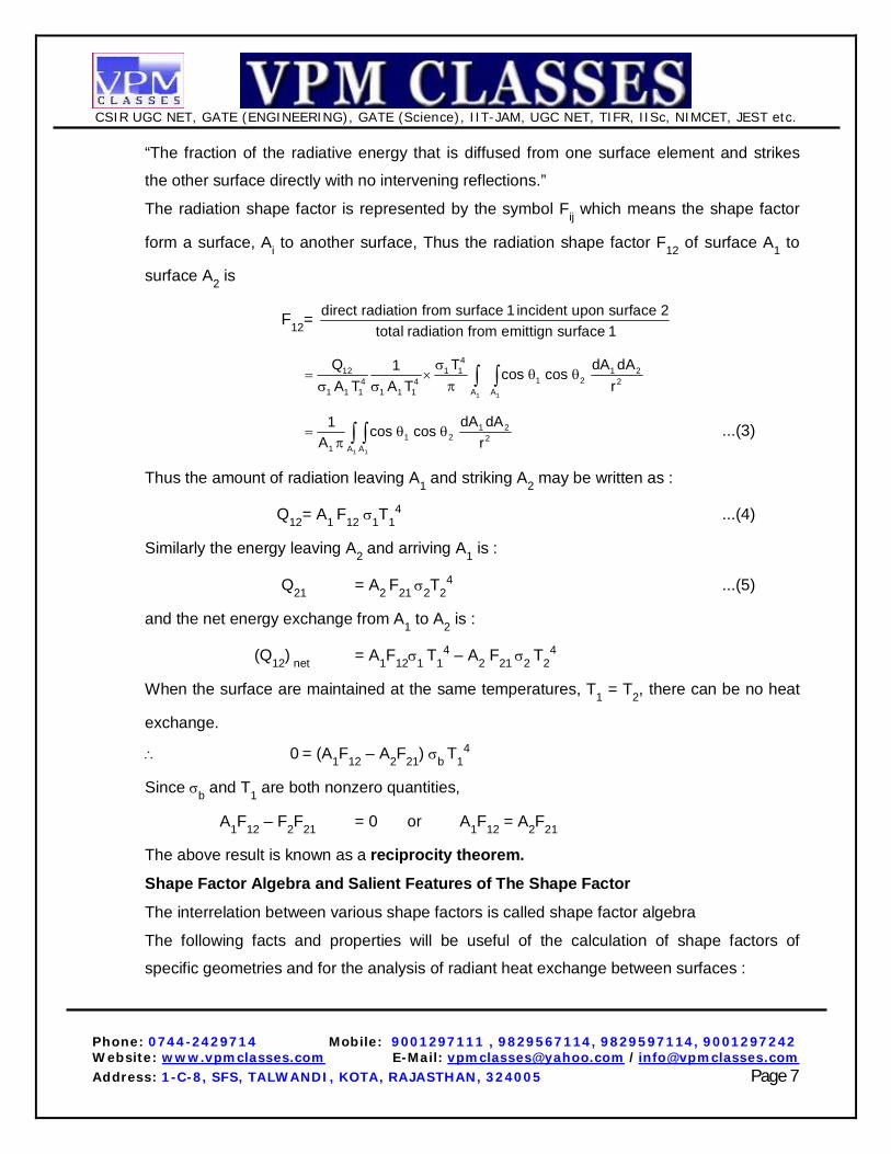
“The fraction of the radiative energy that is diffused from one surface element and strikes
the other surface directly with no intervening reflections.”
The radiation shape factor is represented by the symbol Fij which means the shape factor
form a surface, Ai to another surface, Thus the radiation shape factor F12 of surface A1 to
surface A2 is
F12= direct radiation from surface 1 incident upon surface 2total radiation from emittign surface 1
1 1
412 1 1 1 2
1 24 4 21 1 1 1 1 1 A A
Q T dA dA1 cos cosA T A T r
1 1
1 21 2 2
1 A A
dA dA1 cos cosA r
...(3)
Thus the amount of radiation leaving A1 and striking A2 may be written as :
Q12 = A1 F12 1T14 ...(4)
Similarly the energy leaving A2 and arriving A1 is :
Q21 = A2 F21 2T24 ...(5)
and the net energy exchange from A1 to A2 is :
(Q12) net = A1F121 T14 – A2 F21 2 T2
4
When the surface are maintained at the same temperatures, T1 = T2, there can be no heat
exchange.
0 = (A1F12 – A2F21) b T14
Since b and T1 are both nonzero quantities,
A1F12 – F2F21 = 0 or A1F12 = A2F21
The above result is known as a reciprocity theorem.
Shape Factor Algebra and Salient Features of The Shape Factor
The interrelation between various shape factors is called shape factor algebra
The following facts and properties will be useful of the calculation of shape factors of
specific geometries and for the analysis of radiant heat exchange between surfaces :
CSIR UGC NET, GATE (ENGINEERING), GATE (Science), IIT-JAM, UGC NET, TIFR, IISc, NIMCET, JEST etc.
Phone: 0744-2429714 Mobile: 9001297111 , 9829567114, 9829597114, 9001297242 Website: www.vpmclasses.com E-Mail: [email protected] /[email protected] Address: 1-C-8, SFS, TALWANDI, KOTA, RAJASTHAN, 324005 Page 8
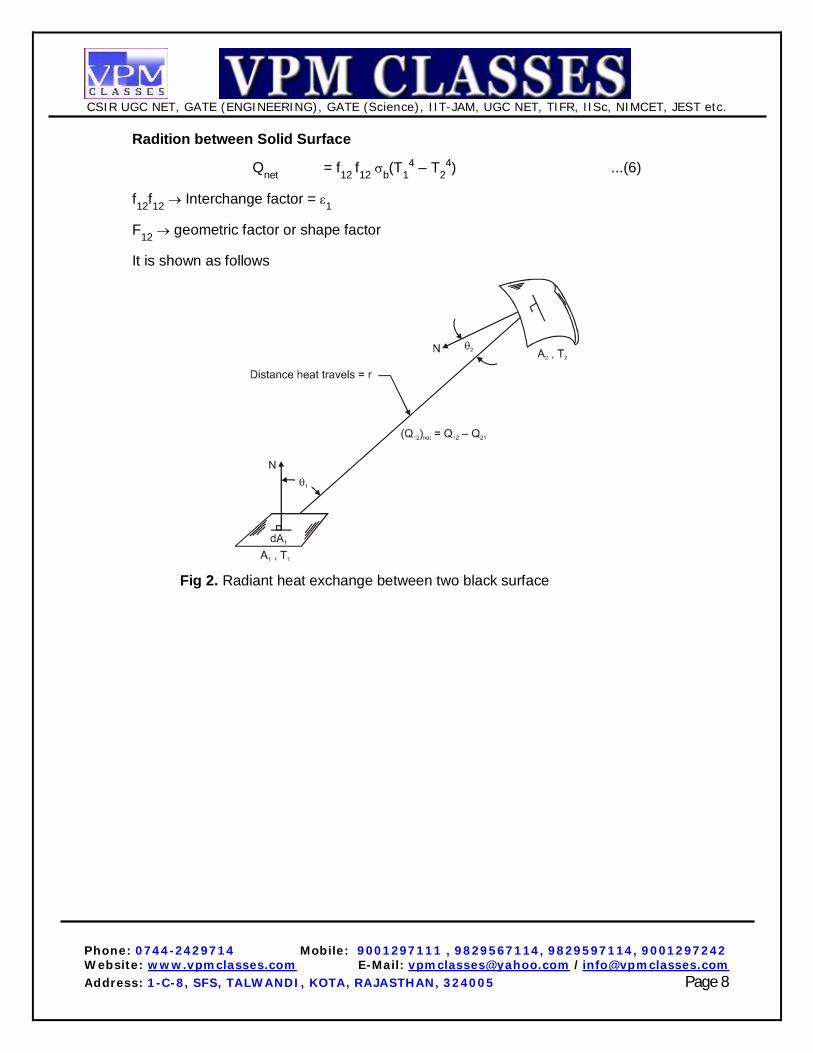
Radition between Solid Surface
Qnet = f12 f12 b(T14 – T2
4) ...(6)
f12f12 Interchange factor = 1
F12 geometric factor or shape factor
It is shown as follows
Fig 2. Radiant heat exchange between two black surface
CSIR UGC NET, GATE (ENGINEERING), GATE (Science), IIT-JAM, UGC NET, TIFR, IISc, NIMCET, JEST etc.
Phone: 0744-2429714 Mobile: 9001297111 , 9829567114, 9829597114, 9001297242 Website: www.vpmclasses.com E-Mail: [email protected] /[email protected] Address: 1-C-8, SFS, TALWANDI, KOTA, RAJASTHAN, 324005 Page 9
CONTROLLER MODES
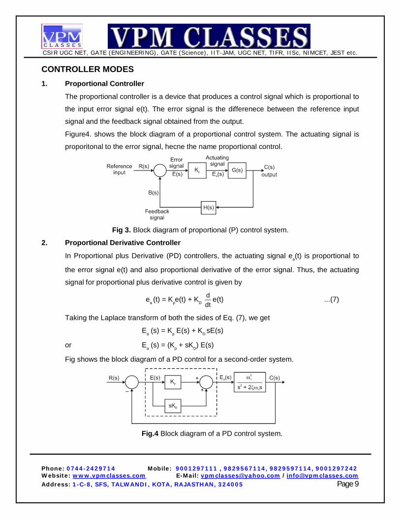
1. Proportional Controller
The proportional controller is a device that produces a control signal which is proportional to
the input error signal e(t). The error signal is the differenece between the reference input
signal and the feedback signal obtained from the output.
Figure4. shows the block diagram of a proportional control system. The actuating signal is
proporitonal to the error signal, hecne the name proportional control.
Fig 3. Block diagram of proportional (P) control system.
2. Proportional Derivative Controller
In Proportional plus Derivative (PD) controllers, the actuating signal ea(t) is proportional to
the error signal e(t) and also proportional derivative of the error signal. Thus, the actuating
signal for proportional plus derivative control is given by
ea (t) = Kpe(t) + KD ddt
e(t) ...(7)
Taking the Laplace transform of both the sides of Eq. (7), we get
Ea (s) = Kp E(s) + KD sE(s)
or Ea (s) = (Kp + sKD) E(s)
Fig shows the block diagram of a PD control for a second-order system.
Fig.4 Block diagram of a PD control system.

CSIR UGC NET, GATE (ENGINEERING), GATE (Science), IIT-JAM, UGC NET, TIFR, IISc, NIMCET, JEST etc.
Phone: 0744-2429714 Mobile: 9001297111 , 9829567114, 9829597114, 9001297242 Website: www.vpmclasses.com E-Mail: [email protected] /[email protected] Address: 1-C-8, SFS, TALWANDI, KOTA, RAJASTHAN, 324005 Page 10
From Fig open-loop transfer function is
G(s) = C(s)E(s)
= (Kp + sKD) ·
2n
2ns 2 s
...(8)
and H (s) = 1 ...(9)
Therefore, closed-loop transfer function of the system si given by
C(s) G(s)R(s) 1 G(s)H(s)
2p D n
2 2 2n D n n p
(K sK )s (2 K )s K
...(10)
The characterstics equation fo the system given by the denominator of Eq. (10) is
2 2 2n D n p ns (2 K )s K 0 ...(11)
2 2n ns 2 s 0 ...(12)
We shall compare (10) with standard Eq. (11)
Now,
2n n D n n n
12 K 2 K 2 '2
where ’ =
D n1 k2
...(13)
Equation (13) shows that effective damping has increased using PD control. This makes the
system response slower with less overshoots increasing delay time. Proportional derivative
control will not affect the steady-state error of the system.This mode of control may be
represented by
c c D s
dp K K pdt
...(14)
where Kc = gain
D = derivative time, min
ps = constant
In this case, we have added to the proportional term another term, Kc D d/d, which is
proportional to the derivative of the error. The values of Kc and D may be varied separately

CSIR UGC NET, GATE (ENGINEERING), GATE (Science), IIT-JAM, UGC NET, TIFR, IISc, NIMCET, JEST etc.
Phone: 0744-2429714 Mobile: 9001297111 , 9829567114, 9829597114, 9001297242 Website: www.vpmclasses.com E-Mail: [email protected] /[email protected] Address: 1-C-8, SFS, TALWANDI, KOTA, RAJASTHAN, 324005 Page 11
be knobs on the controller. Other terms that are used to describe the derivative action are
rate control and anticipatory control. This response is obtained by introducing the inner
function (t) = At into Eq. (14) to obtain
p(t) = AKct + AKcD + ps
Fig.5 Response of a PD controller to a linear input in error
Notice that p changes suddenly by an amoun AKcD as a result of the derviative action and
then cagnes linearly at a rate AKc. The effect of derivative action in this case is to anticipate
the linear change in error by adding additional output AKc D to the proportional action.
3. Proportional Iniegral Controller
In proportional plus Integral controllers, the actuating signal consists of proportinoal error
signal added to the integral of the error signal. The actuating signal in time domain is given
by
ea (t) = Kpe(t) + K t
0
e( ) d ...(15)
Here the constants KP and K are proportional and integral gains known as controller
parameters.
By taking the Laplace transform of both sides of Eq. (15), we get
Ea (s) = KP E(s) + K K(s)
s
or Ea (s) =
PK
Ks
E(s) ...(16)
CSIR UGC NET, GATE (ENGINEERING), GATE (Science), IIT-JAM, UGC NET, TIFR, IISc, NIMCET, JEST etc.
Phone: 0744-2429714 Mobile: 9001297111 , 9829567114, 9829597114, 9001297242 Website: www.vpmclasses.com E-Mail: [email protected] /[email protected] Address: 1-C-8, SFS, TALWANDI, KOTA, RAJASTHAN, 324005 Page 12
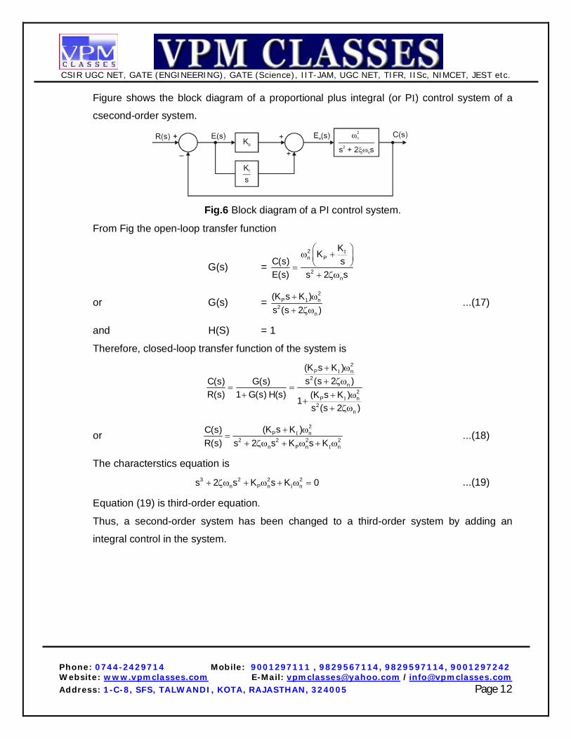
Figure shows the block diagram of a proportional plus integral (or P) control system of a
csecond-order system.
Fig.6 Block diagram of a PI control system.
From Fig the open-loop transfer function
G(s) =
2n P
2n
KKsC(s)
E(s) s 2 s
or G(s) =
2P 1 n
2n
(K s K )s (s 2 )
...(17)
and H(S) = 1
Therefore, closed-loop transfer function of the system is
2P n
2n
2P n
2n
(K s K )s (s 2 )C(s) G(s)
R(s) 1 G(s) H(s) (K s K )1s (s 2 )
or
2P n
2 2 2 2n P n n
(K s K )C(s)R(s) s 2 s K s K
...(18)
The characterstics equation is
3 2 2 2n P n ns 2 s K s K 0 ...(19)
Equation (19) is third-order equation.
Thus, a second-order system has been changed to a third-order system by adding an
integral control in the system.

CSIR UGC NET, GATE (ENGINEERING), GATE (Science), IIT-JAM, UGC NET, TIFR, IISc, NIMCET, JEST etc.
Phone: 0744-2429714 Mobile: 9001297111 , 9829567114, 9829597114, 9001297242 Website: www.vpmclasses.com E-Mail: [email protected] /[email protected] Address: 1-C-8, SFS, TALWANDI, KOTA, RAJASTHAN, 324005 Page 13
4. Proportional-Integral and Derivative Controller
A PID controller (Proportional plus Integral plus Derivative Controller) produces an output
signal consisting of three terms – one proportional to error signal, another one proportional
to integral of error signal and third one proportional to derivative of error signal.
The combination of proportional control action, integral control action and derivative control
action is called PID control action. The combined action has the advantage of each of the
three individual control actions.
The Proportional controller stabilizes the gain but produces a steady-state error. The
integral controller reduces or eliminates the steady-state error. The derivative controller
reduces the rate of change of error. The main advantages of PID controllers are higher
stability, no offset and reduced overshoot.
PID controllers are commonly used in process control industries.
The actuating signal or outupt signal from a PID controlle rin time domain is given by
ea (t) = KP e(t) + K t
D0
dee( )d Kdt
...(20)
In the s-domain, the output signal from the controller is
Ea (s) =
P DK
K K s E(s)s
...(21)
Figure shows a PID controller for second-order system. The closed-loop transfer function of
a PLD controller for a second-order system is given by
2 2n D P
3 2 2 2 2n D n P n n
(K s K s K )C(s)R(s) [s (2 K )s K s K ]
...(22)
Fig.7 Block diagram of a PID controller for second-order system.
The mode of control is combination of the previous modes and is given by the expression

CSIR UGC NET, GATE (ENGINEERING), GATE (Science), IIT-JAM, UGC NET, TIFR, IISc, NIMCET, JEST etc.
Phone: 0744-2429714 Mobile: 9001297111 , 9829567114, 9829597114, 9001297242 Website: www.vpmclasses.com E-Mail: [email protected] /[email protected] Address: 1-C-8, SFS, TALWANDI, KOTA, RAJASTHAN, 324005 Page 14
1c
c c D s01
Kdp K K dt pdt
...(23)
In this case, the controller contains three knobs for adjusting Kc, D, and 1.
Fig.8 Response fo a typical control system showing the effects of various modes of control.