l a u an m s r e …with installation instructions banks...
TRANSCRIPT

1 2 / 1 6 / 0 9 P N 9 6 7 6 7 v . 3 . 0
Banks Stinger® System2003-2004 Dodge ISB 5.9L Cummins(24-valve) ISB Pickup Trucks
T H I S M A N U A L I S F O R U S E W I T H S Y S T E M S 4 9 5 1 6 t o 4 9 5 1 9
ow
ner
S m
an
ua
L…
with
inst
alla
tion
inst
ruct
ions
Gale Banks Engineering 546 Duggan Avenue • Azusa, cA 91702 (626) 969-9600 • Fax (626) 334-1743
Product Information & Sales: (800) 438-7693
bankspower.com
© 2 0 0 9 G A L E B A N k S E N G I N E E R I N G

General Installation Practices1. For ease of installation of your Banks Stinger, familiarize yourself with the procedures by reading the entire manual before starting work. This instruction manual contains 24 pages of text, illustrations and parts listing.
2. Disconnect the ground cable from the battery before beginning work. If there are two batteries, disconnect both.
3. Route and tie wires and hoses a minimum of 6 inches away from exhaust heat, moving parts and sharp edges. clearance of 8 inches or more is recommended where possible.
4. When raising the vehicle, support it on properly weight-rated safety
stands, ramps or a commercial hoist. Follow the manufacturer’s safety precautions. Take care to balance the vehicle to prevent it from slipping or falling. When using ramps, be sure the front wheels are centered squarely on the topsides; put the transmission in park; set the hand brake; and place blocks behind the rear wheels.
Caution! Do not use floor jacks to support the vehicle while working under it. Do not raise the vehicle onto concrete blocks, masonry or any other item not intended specifically for this use.
5. The installation should be performed at a time when the vehicle has been allowed to completely cool. This installation requires the installer to work near surfaces that may remain hot after the vehicle has been run. Failure to allow the vehicle to cool may result in personal injury.
6. During installation, keep your work area and components clean to avoid possible dirt entry into the engine.
7. Save this Owner’s Manual as a reference for system maintenance and service.
NotificationThe Banks Ram-Air Filter comes pre-oiled and no oiling is necessary for initial installation. Service the filter as specified in the cleaning and Oiling the Banks Ram-Air Filter Section of this manual.
Tools Required: These tools are necessary for all levels of installation unless otherwise specified.• 1⁄4” and 3⁄8” drive ratchets with inch and metric sockets including 5⁄16”, 7⁄16” deep 1⁄4” drive sockets and a 1⁄4” drive extension• Inch and metric combination or open-end wrenches• Standard and Phillips head screwdrivers• Standard and needle-nose pliers• Pocket or X-Acto knife• Clean shop towels or rags• Drill motor• Tap handle• 1⁄8” Allen wrench• 3⁄16” and 7⁄16” drill bits• 1⁄4” NPT tap• Heat gun (suggested) or cigarette lighter• Pry bar or large groove-joint (water pump) pliers• Wire crimping/stripping tool• Oxy-acetylene torch or reciprocating saw
Highly recommended tools and supplies:
• Inch-pound and foot-pound torque wrenches• Compressed air source and hose• Air pressure regulator• Rubber tipped air blowgun• Multimeter or 12-volt test light• Penetrating oil or light lubricant spray• 90-degree motor drill
Dear Customer,
If you have any questions concerning the installation of your Banks Power system, please call our Technical Service Hotline at (888) 839-2700 between 7:00 am and 5:00 pm (PT). If you have any questions relating to shipping or billing, please contact our Customer Service Department at (888) 839-5600.
Thank you.
2 | 9 6 7 6 7 v . 3 . 0

EXHAUST REMOVALImportant: DO NOT DAMAGE CATALYTIC CONVERTER TUBING DURING THE REMOVAL PROCESS.
1. From under the vehicle, remove the entire factory exhaust system. Starting at the rear of the vehicle, remove each component by either cutting through the pipe near the clamps or by removing the clamps and heating the joints with an oxyacetylene torch to allow crimped pipes to separate. DO NOT CUT OR DAMAGE CATALYTIC CONVERTER TUBING DURING THE REMOVAL PROCESS. Remove the hanger pins from the rubber hangers with a pry bar. (Spray lubricant will ease hanger removal.)
2. Remove the clamp attaching the turbine outlet pipe (T.O.P.) to the catalytic converter headpipe (or intermediate pipe if applicable) and remove the catalytic converter assembly or intermediate pipe. Remove the band-clamp that attaches the T.O.P. to the turbine outlet elbow and remove the factory T.O.P. from the vehicle.
3. Remove the v-band clamp that attaches the turbine outlet elbow to the turbine housing and remove the turbine outlet elbow from the vehicle. Retain the V-band clamp for reassembly.
TURBOCHARGER REMOVAL4. Loosen the clamps that attach the air inlet tube to the air filter housing and to the turbocharger, and remove
the air inlet tube from the vehicle. Remove the air filter housing from the vehicle. This will allow easier access to the turbocharger.
5. Loosen the upper hose clamp on the turbocharger oil drain-tube hose that is located between the two sections of the oil drain tube.
6. Disconnect the oil supply hose at the turbocharger. Disconnect compressor outlet hose that goes to the intercooler.
7. Remove the turbocharger mounting nuts/bolts and the turbocharger from the exhaust manifold. clean and inspect the exhaust flange mounting surfaces on the exhaust manifold. Make sure the surface is clean and dry.
CAUTION: Anytime the turbocharger is removed from the engine, take care that no foreign objects enter any of the turbocharger connections on the engine or the turbocharger. Foreign objects entering air, exhaust, or oil connections may cause major damage to the engine and/or turbocharger and is not covered under any warranty. Cover the open end of the intercooler pipe with a clean rag, as this pipe is very susceptible to foreign object entry.
8. Stuff clean shop towels into the compressor outlet and inlet hoses to prevent contamination from entering the pipes. cover the turbo oil drain pipe to avoid contamination.
THERMOCOUPLE INSTALLATION9. The thermocouple monitors the temperature of the exhaust gases entering the turbocharger at the turbine housing. Installation requires that the exhaust manifold be drilled near the outlet of the manifold adjacent to the turbine housing. For this reason it is essential that the turbocharger be removed from the engine in order to clean out any metal chips from drilling that could cause turbine blade damage.The cummins ISB engine uses a divided exhaust manifold. The thermocouple may be installed to sample exhaust temperature in either exhaust passage. We recommend the rear passage (toward the firewall).
10. Stuff a small clean shop towel or rag 4 to 5 inches into the rear exhaust manifold passage through the turbocharger mounting flange. This is to prevent chips from entering the manifold while drilling and tapping.
11. Drill through the exhaust manifold into the rear passage as shown in Figure 1. Use a 7⁄16” drill, keeping the drill perpendicular to the manifold surface. NOTE: A 90º drill will work better.
12. Tap the drilled hole with a 1⁄4” NPT pipe tap. check the thread depth as you tap by periodically removing the tap and screwing the pipe coupling into the tapped hole. The coupling should thread in 3 to 3-1⁄2 turns hand tight. Do not install the probe in place at this time.
9 6 7 6 7 v . 3 . 0 | 3

13. Remove all loose chips from the exhaust manifold. A shop vacuum or small brush will help. Now remove the rag using a welding rod or coat hanger bent into a hook. caution! Make sure rags are removed from exhaust manifold prior to reinstalling turbocharger!
14. Install the thermocouple in the manifold using anti-seize on the threads.
BIG HEAD ACTUATOR INSTALLATION15. Remove the actuator pressure hose on the turbocharger by removing the two (2) clamps. Remove the two (2) nuts holding the actuator to the bracket and remove the actuator.
16. Install the BigHead® actuator in place of the factory actuator. Install the supplied actuator pressure hose and secure it by using the two (2) supplied spring clamps. See Figure 2.
17. Turn the rod end link on the threads of the actuator rod until the end link will slip over the pin on the wastegate arm. Turn the rod end clockwise an additional six (6) full turns, such that it will add preload to the wastegate.
18. Apply a regulated supply of air pressure to the nipple of the actuator until the rod extends enough to slip over the pin on the wastegate arm. Reinstall the E-clip on the pin. Tighten all bolts and nuts that remain loose.
TURBOCHARGER INSTALLATIONCAUTION: Remove all the rags that are inside the compressor hoses and the exhaust manifold before re-installing the turbocharger.
19. Install the new turbine inlet gasket provided and apply a dab of anti-seize compound to the
four turbo mounting studs. Install the turbocharger on the exhaust manifold. As the turbocharger is reinstalled, slip the oil drain tube into the drain hose. Tighten the turbocharger mounting nuts to 24 ft-lbs. Tighten the oil drain hose clamp.
20. Reconnect and tighten the turbo oil supply hose.
Figure 1
Figure 2
4 | 9 6 7 6 7 v . 3 . 0

Figure 4
21. Re-install the air filter housing that was previously removed.
EXHAUST INSTALLATION22. Make sure the mating surface is clean and free of oil, attach the supplied T.O.P. gasket to the Banks T.O.P. Loosely place the factory V-band clamp on the Banks T.O.P. Install the Banks T.O.P. to the turbine housing (note: the factory turbine outlet elbow will not be used). Loosely snug the V-band clamp assuring gasket and T.O.P. is aligned properly. See Figure 3 on page 6-7.
For vehicles equipped with catalytic converter, skip to STEP 24. For non-cat vehicle, continue to STEP 23.
23. FOR VEHICLES THAT ARE NOT EQUIPPED WITH A CATALYTIC CONVERTER: install the supplied Banks front intermediate pipe and supplied gasket onto the previously installed Banks T.O.P. Place a small amount of anti-seize onto the four (4) 7⁄16” bolts. Loosely install the supplied 7⁄16” hardware onto the T.O.P. and intermediate pipe flange (see Figure 3 on page 6-7). Proceed to Step 27.
24. FOR VEHICLES EQUIPPED WITH CATALYTIC CONVERTER:IMPORTANT: If the vehicle is equipped with a catalytic converter, it should be inspected. Diesel catalysts may become plugged with soot and can cause a restriction to exhaust flow, impeding performance. Shine a powerful flashlight into the inlet end of the converter. Observe the light through the other end of the converter. The full circle of the flashlight should be visible without any blockage in the grid work of the catalyst. If excessive soot is observed, the catalyst may need to be cleaned. TAkE PREcAUTIONS to avoid blowing soot toward the work area or where it could be inhaled. ALWAYS use breathing protection. Also inspect the catalyst for damage (i.e. chips, bent corners, etc.) to the grid work. If your catalytic converter is damaged, it may be covered under your vehicle’s emissions warranty.
CAUTION: The following step involves cutting a stainless steel tube. Safety glasses should be worn during any cutting operation, and care should be taken to avoid injury due to sharp edges and burrs.
With the catalytic converter removed from the vehicle and the headpipe removed from the converter, measure 13” inward from the outlet tubing rim (3-1⁄2” of tubing from the outlet weld should remain). Using a reciprocating saw or equivalent, squarely cut and remove 13” from the converter outlet tubing. See Figure 4.
25. Install the supplied Banks front intermediate pipe and supplied gasket onto the previously installed Banks T.O.P. Place a small amount of anti-seize onto the four (4) 7⁄16” bolts. Loosely install the supplied 7⁄16” hardware onto the T.O.P. and intermediate pipe flange.
26. Install the supplied 3-1⁄2” clamp onto the catalytic converter inlet. Place the catalytic converter onto the previously installed intermediate pipe. Loosely snug the clamp on the catalytic converter inlet.
27. Place a supplied 4” clamp onto the front of the supplied intermediate pipe. Install the intermediate pipe onto the catalytic converter outlet or the front intermediate pipe. Lightly snug the band-clamp near the rim of the intermediate pipe.
9 6 7 6 7 v . 3 . 0 | 5

Figure 3
no. Stinger System Components Qty1 MONSTER TURBINE OUTLET PIPE 12 FRONT-INTERMEDIATE PIPE (NON-CAT. CONV. SYSTEMS ONLY)13 FRONT-INTERMEDIATE PIPE (CAT. CONV. SYSTEMS ONLY) 14 INTERMEDIATE PIPE 15 EXTENSION PIPE (QUAD-CAB, LONG BED MODELS) 16 BANKS DYNAFLOW MUFFLER 17 MONSTER TAILPIPE 18 POLISHED 5” EXHAUST TIP 19 TURBINE OUTLET GASKET 110 T.O.P. GASKET (4-BOLT) 111 EXHAUST CLAMP, 4” 3 *12 EXHAUST CLAMP, 3-1⁄2” (CAT. CONV. SYSTEMS ONLY) 1
91
1314
14 152
10
14 15
3 12
114
5
11
11
** Factory V-band clamp (not supplied)
**
no. Stinger System Components Qty
13 HEX BOLT, 7⁄16-20 X1.50” 4 14 WASHER, FLAT SAE, 7⁄16” 8 15 NUT, CRIMPLOCK, 7⁄16-20” 4 16 BIG HEAD ACTUATOR 1 CLAMP, 3⁄8” SPRING BAND, GREEN 2 HOSE, SILICONE, 1⁄4” BULK 1 17 HARNESS, GAUGE WIRING 1 18 PANEL, TWO-GAUGE MOUNTING 1 19 GAUGE, BOOST 1 20 GAUGE, PYROMETER 1 21 AIR FILTER ELEMENT 1 AIR FILTER SERVICE KIT 1 22 OTTOMIND, STINGER 1 23 WIRE HARNESS 1 24 TCC MONITOR CABLE 1 25 EXTENSION WIRE 1
no. Stinger System Components Qty 26 THERMOCOUPLE, GROUNDED-JUNCTION 1 27 LEADWIRE, PYROMETER, ELECTRIC 1 28 TURBINE INLET GASKET 1 BYPASS PLUG, OttoMind 1 CABLE TIE, BLACK, 7” 15 CONNECTOR, T-TAP, RED 3 ANTI SEIZE, 5 GRAMS 1 DECAL, STOP DO NOT DISCARD 1 29 UROCAL, BANKS POWER, SMALL 2 OWNERS MANUAL, STINGER SYSTEM 1 PRODUCT REGISTRATION CARD 1 WARRANTY STATEMENT 1
* Quad-Cab, Long Bed models contain four (4) 4” exhaust clamps
General assembly Diagram
6 | 9 6 7 6 7 v . 3 . 0

711
8
6
9 6 7 6 7 v . 3 . 0 | 7

28. For quad cab long bed (160.5” wheelbase) models only: Place a supplied 4” clamp onto the front of the supplied extension pipe. Install the extension pipe hanger pin into the corresponding rubber hanger. Connect the extension pipe onto the intermediate pipe.
29. Install the Dynaflow muffler. Install a 4” clamp onto the muffler outlet. Route the tailpipe over the rear axle housing and into the muffler outlet. Install the tailpipe hanger pin into the corresponding rubber hanger. Loosely snug the 4” clamp on the muffler outlet.
30. Install the 5” Monster tailpipe tip on the exhaust. Keep the wrapping on until installation is complete. The tip should be rotated so the clamp nut is pointing down. For a fleet-side truck the 5” tip should be hung 1” past the end of the tailpipe. For a dually, the tip should be 3-1⁄2” past the end of the tailpipe or where aesthetically pleasing.
31. With everything positioned properly, begin to tighten the clamps starting with the ones closest to the turbo and working your way back. Torque the V-band clamp to 80 in-lbs. Evenly torque the exhaust clams to 35 ft-lbs. Torque the 7⁄16” hardware to 48 ft-lbs. Make sure that each slip is fully inserted (+/- 1⁄2 inch) and that all mount hangers are in the forward position. See Figure 5.
32. Remove the protective covering from the tailpipe tip. Caution: The protective covering may ignite and burn if not removed prior to running the engine.
OTTOMIND INSTALLATION For 2003 vehicles, start from Step 33. For 2004 vehicles, start from Step 34.
33. FOR 2003 VEHICLES ONLY: Locate the large black electrical connector (c130) on the driver side between the battery and the firewall. See Figure 6. Remove the two (2) plastic screws on the sides of the connector and move the connector aside. Retain the two (2) screws and the two (2) retainers for re-installation.
34. Locate the rubber grommet on the drivers side firewall. Using a utility knife, make a 1.5-inch-long slit in the grommet next to the wire harness. Be careful not to cut or damage the harness. See Figure 7 for the proper location of the required cut. Insert a screwdriver from the engine compartment into the cut hole and thrust it through the grommet.
35. Inside the vehicle, remove the lower dash panel beneath the steering column by removing the two (2) screws at the bottom of the panel. Retain the screws for re-installation. NOTE: There are also two (2) clips located at the top corners of the panel, which hold the panel in place. These clips can be released by gently pulling on the corners of the panel. Use caution to avoid damaging the panel during removal.
36. Remove the electrical connector bracket on the left hand side of the support below the steering column in front of the firewall by removing the two (2) bolts. This will allow access to the inner grommet. See Figure 8.
37. cut the grommet on the firewall inside the vehicle along the hole created by the screwdriver in Step 34.
38. Locate the OttoMind wire harness end with the 8- and 10-pin connector. From the engine compartment, push this end through the hole cut in the grommet through
Figure 5
8 | 9 6 7 6 7 v . 3 . 0

the firewall. NOTE: Taping the end of the harness to a piece of stiff wire (i.e. coat hanger) may make routing the harness through the firewall a simpler task. The stiff wire should be pushed through the slit in the grommet and then the wires can be attached to the stiff wire and pulled through the hole in the firewall.
CAUTION: Pull gently to avoid damage to the wire harness connectors. Always pull on the wire harness convolute sheath rather than the wires themselves.
39. From inside the vehicle, continue to pull the harness through the firewall until the main harness is approximately 22” inside the cab.
40. FOR AUTOMATIC TRANSMISSION VEHICLES ONLY: Insert the end of the provided Tcc wire harness with the 4-pin connector through the grommet from the engine compartment side using the same hole. Pull the Tcc wire harness from inside the cab until approximately 22” of the wire is inside. Note: The TCC wire harness is not applicable on vehicle with a manual transmission.
41. In the engine compartment, locate the CAN BUS connector on the drivers side of the engine. It is a flat 3-pin connector located on top of the fuel lift pump below the map sensor next to the ECM. Remove the weather seal plug and insert OttoMind cAN BUS connector into this connector. See Figure 9.
Figure 6
Figure 7
Figure 8
9 6 7 6 7 v . 3 . 0 | 9

42. Find the Fuel Rail Pressure (FRP) sensor on the fuel rail. It is located on the drivers side of the engine. Unplug the factory connector and plug it into the OttoMind harness. Plug the OttoMind FRP connector into the sensor. See Figure 10.
43. Locate the Manifold Pressure (MAP) sensor on top of the intake manifold. Unplug the factory connector and plug it into the OttoMind harness. Plug the OttoMind MAP connector into the sensor. See Figure 10.
CAUTION: The camshaft position sensor and the crankshaft position sensor have the same type of connectors and they are in close proximity to one another. Make sure the right connectors are used when installing these connections. Refer to Figure 11 for their locations on the OttoMind wire harness.
Figure 10
Figure 9
10 | 9 6 7 6 7 v . 3 . 0

44. Find the crankshaft position sensor on the lower front left side of the engine. It is behind the engine crankshaft pulley (engine harmonic balancer). Unplug the factory connector and plug it into the corresponding crankshaft position sensor connector on the OttoMind harness. Plug the OttoMind crankshaft position sensor connector into the sensor. Take care to route the wire harness away from the power steering pump and secure it with the supplied cable ties. See Figure 12.
45. Locate the camshaft position sensor below the fuel injection pump between the timing gear cover and the EcM. Unplug the factory connector and plug it into the corresponding camshaft position sensor connector on the OttoMind harness. Plug the OttoMind camshaft position sensor connector into the sensor. See Figure 13.
Caution: It is very important that you select the proper wire. The Banks OttoMind will not function properly if installed incorrectly.
Figure 11
Figure 12
9 6 7 6 7 v . 3 . 0 | 11
For 2003 automatic transmission vehicles, follow Steps 46 through 49.
For 2003 vehicles with a manual transmission, skip to Step 49.
For 2004 vehicles with an automatic transmission, follow Steps 50 through 52.
For 2004 vehicles with a manual transmission, skip to Step 52.
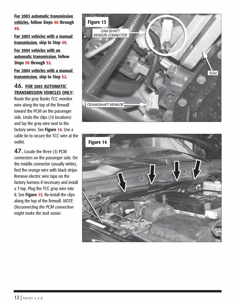
46. FOR 2003 AUTOMATIC TRANSMISSION VEHICLES ONLY: Route the gray Banks Tcc monitor wire along the top of the firewall toward the PcM on the passenger side. Undo the clips (10 locations) and lay the gray wire next to the factory wires. See Figure 14. Use a cable tie to secure the Tcc wire at the outlet.
47. Locate the three (3) PcM connectors on the passenger side. On the middle connector (usually white), find the orange wire with black stripe. Remove electric wire tape on the factory harness if necessary and install a T-tap. Plug the Tcc gray wire into it. See Figure 15. Re-install the clips along the top of the firewall. NOTE: Disconnecting the PCM connection might make the task easier.
Figure 13
Figure 14
12 | 9 6 7 6 7 v . 3 . 0

48. Locate the solid red wire in the wire loom entering c130 connector. This is the same connector removed in Step 1. Install a T-tap on the red wire and plug the blue Tcc wire into it. See Figure 16.
49. FOR ALL 2003 VEHICLES ONLY: Locate the green wire with black tracer in the wire loom entering c130 connector. This is the same connector removed in Step 1. Install a T-tap on this wire. Plug the red OttoMind wire into this T-tap. Skip to Step 53.
50. FOR 2004 AUTOMATIC TRANSMISSION VEHICLES ONLY: Plug the TCC extension into the blue Tcc wire. Using the wire harness on the two (2) connectors next to the main brake cylinder as a guide (see Figure 17), route the blue and gray Tcc wires toward the transmission solenoid assembly that is sitting on the transmission. It is located underneath the drivers side of the vehicle. See Figure 18A. Secure the wire using cable ties along the way.
Figure 15
Figure 16
9 6 7 6 7 v . 3 . 0 | 13

51. Find the yellow wire with orange stripe on the solenoid assembly. Apply a generous amount of the supplied dialectric grease into a T-tap and install it on this wire. Insert the blue Tcc wire into this T-tap. Find the yellow wire with light blue stripe. Apply a generous amount of the supplied dialectric grease into a T-tap and install it on this wire. Insert the gray Tcc wire into this T-tap. See Figure 18B
52. FOR ALL 2004 VEHICLES ONLY: Locate the two (2) electrical connectors next to the main brake cylinder. Find the pink wire with gray stripe on the connector closest to the brake cylinder. Install a T-tap on this wire. Insert the 7” red extension wire into the red OttoMind wire. Plug this red wire into the T-tap. See Figure 19.
Figure 18A
Figure 17
14 | 9 6 7 6 7 v . 3 . 0

53. Inside the cab, plug the main 8- and 10-pin connectors from the wire loom into the OttoMind box.
54. On vehicles with automatic transmissions, plug the TCC wire harness into the OttoMind box.
55. In the engine compartment, unbolt the nut from the ground terminal on the drivers side battery. Locate the ring terminal on OttoMind wire harness. Install this ring terminal onto the battery ground and re-install the nut. See Figure 20.
56. FOR ALL 2003 VEHICLES ONLY: Reinstall the large black electrical connector (c130) that was removed in Step 1.
Note: Go over the entire installation as a precautionary check to ensure that all clamps are tight, wiring and hoses are properly routed, and connections are correct and tight. Make sure that the wire harness is not lying in the way of the brake and accelerator pedals.
Figure 18B
19
9 6 7 6 7 v . 3 . 0 | 15

DYNAFACT Instrumentation Installation57. choose a suitable location under the lower edge of the dash for the mounting of the instrument panel provided where the driver can conveniently view it.
Note: Molded pillar mount and additional gauges are available through Gale Banks Engineering.
58. Using the panel as a template, drill two 3⁄16” diameter holes in the dash and mount the panel with the supplied machine screws, nuts and star washers provided.
59. Locate the supplied gauge wire harness with the 4-pin connector. Plug the 4-pin connector into the corresponding 4-pin receptacle from the EconoMind wire harness. See Figure 3.
60. Install the DynaFact boost and pyrometer gauges in the mounting panel using the clamps and thumbnuts provided. Plug the BLAck wire lead to the male spade terminal on the BLAck wire of each gauge wire harness. Plug the YELLOW wire into the Yellow wire of the boost gauge wire harness and the RED wire into the RED wire of the pyrometer gauge wire harness. The ORANGE wire remains unused.
61. connect the 4-pin connector of each gauge into the back of its corresponding gauge.
a. crimp the remaining Black and RED wires from each 4-pin connector gauge harness to the butt connectors as shown in Figure 21.
b. Strip one end of the RED wire and crimp to one of the butt connectors attached to the gauge harnesses in step ‘a’.
c. Strip one end of the BLAck wire and crimp to the other butt connector attached to the gauge harnesses in step ‘a’.
d. Route the RED wire to the fuse box. Locate the appropriate fuse for instrument lighting in the owner’s manual. cut the RED wire as required and strip the end. crimp the push on connector to the RED wire and connect to the fuse as shown in Figure 21. Alternatively, locate power wire to dimmer switch and install T-tap. cut the RED wire as required and strip the end. crimp the push on T-tap connector to the RED wire and connect to T-tap on dimmer power wire.
e. Locate a metal surface that will serve as an acceptable chassis ground. cut the BLAck wire to a sufficient length that will allow it to reach the chassis ground and strip the end. crimp the ring terminal to the BLAck wire as shown in Figure 21.
f. Drill a 1⁄8” hole, if required, to attach the ring terminal to the chassis ground. Caution: If drilling, check the backside to make sure there are no components that may be damaged by drilling.
g. Use the supplied self-tapping screw to secure the ring terminal to the chassis ground.
Banks Ram-Air Filter Installation62. Locate the engine air filter box on the passenger’s side of the vehicle. Remove the cover by releasing the four (4) clips on the
Figure 20
16 | 9 6 7 6 7 v . 3 . 0

side of the housing and slide the cover toward the engine.
63. Remove the old air filter element from the filter housing and replace it with the Banks Ram-Air filter element. Place the Banks filter element in the right orientation and check the filter seal is seating properly around the housing to ensure no leakage.
For proper maintenance and service on the Banks Ram-Air Filter, refer to cleaning and Oiling The Banks Ram-Air Filter on page 22.
64. Slide the tabs on the cover into the slots on the air filter box. Press the cover down gently and re-attach the four (4) clips on the side to securely clamp the cover.
Learning Transmission
Your Ottomind displays the “4,3” diagnostic code (refer to “TroubleShooting” section on how to read codes) when it needs to learn your transmission configurations. This always occurs when the OttoMind is first installed on the truck.
Banks OttoMind is equipped with advanced safety features to preserve your automatic transmission. One of them is the capability to detect the occurrence of transmission slip, and it will automatically derate the engine output power accordingly. Before this safety feature can take effect, the OttoMind needs to learn that your truck is equipped with an automatic transmission.
65. Reconnect all battery terminals.
The following driving test shall be performed in an area where speeds of this nature are safe and traffic is light. For vehicles with a manual transmission, follow Steps 66 through 67. For vehicle with automatic
transmission, follow Steps 68 through 70.
While driving, listen for any exhaust leaks or rattles, or intake boost leaks. After the engine cools, re-tighten clamps and hoses if leaks are detected.
Figure 21
9 6 7 6 7 v . 3 . 0 | 17

66. To teach the OttoMind that your truck is equipped with a manual transmission, drive the truck at a vehicle speed of over 40 MPH for at least 2 minutes.
67. The “4,3” diagnostic code will be eliminated. Proceed to “Learning Engine Power Rating.” Repeat Step 66 if necessary to eliminate code.
68. To teach the OttoMind that your truck is equipped with an automatic transmission, drive your truck under light load with overdrive turned on (4th gear). Obtain a vehicle speed of over 60 MPH until torque converter is locked (the torque converter is usually locked at speed over 60 MPH). Maintain this speed steadily with the torque converter locked for at least 30 seconds.
69. continue to drive. Slow down and turn off overdrive and obtain vehicle speed of over 50 MPH until torque converter is locked ( the torque converter is usually locked at speeds over 50 MPH with the overdrive off). Maintain the speed steadily with the torque converter locked for at least 30 seconds.
70. Once the transmission is learned, the “4,3” diagnostic code will be eliminated. Proceed to “Learning Engine Power Rating.” If the code is not eliminated, repeat Steps 68 to 69.
Learining Engine Power Rating
Your OttoMind needs to know the correct power rating of your engine in order to provide the proper
calibration and tuning. The correct engine power rating can be found on the tag in the engine compartment at one of the locations shown in Figure 22. The power rating is typically shown in the upper right hand corner of the tag. The rated power should be 235, 250 or 305 HP. If the rating is different, contact Gale Banks technical Support. Follow the steps described below (Step 71
to 76) to teach your OttoMind the power rating of your engine. As shipped, the OttoMind is calibrated for a 305HP (High Output) engine. If you have a 305HP rated engine, skip to “checking Engine Performance” Section.
71. If you have a 235 HP or 250 HP rated engine, remove the thermocouple leadwire from the
Figure 23
Figure 22
18 | 9 6 7 6 7 v . 3 . 0

OttoMind box connection. Insert the provided engine rating jumper key into the OttoMind box thermocouple connection. See Figure 23.
72. Turn the key to ON position (DO NOT start the engine) and wait 5 seconds.
73. Turn the key to OFF position, wait 5 seconds and turn the key to ON position (Do NOT start the engine) and wait 5 seconds.
74. Again, turn the key to OFF position, wait 5 seconds and turn the key to ON position (DO NOT START ENGINE) and wait 5 seconds.
75. When the procedure is completed correctly, the OttoMind will flash the red LED once.
76. Turn the key to the OFF position and remove the engine rating jumper key. Re-install the thermocouple leadwire into the OttoMind box.
Note: Each time the key is turned on, the OttoMind will flash the red LED once at powerup to indicate that it has calibrated as a 235HP/250HP engine rating. A 305HP rated engine calibration does not flash a red LED. If you have incorrectly used a 235HP/250HP calibration on a 305HP rated engine, excessive fuel rail pressure will result and the OttoMind will automatically adjust the calibration to the 305HP rated engine level and red LED will not flash at powerup. A “4,4” diagnostic code will be generated and stored in the OttoMind in the process. A “4,4” will also be generated and stored in
the OttoMind on a 235HP or 250HP rated engine if excessive fuel rail pressure is detected. This “4,4” code is eliminated and cleared when the key is turned off and turned back on.
If “4,4” diagnostic code keeps being generated and stored on your OttoMind, contact Gale Banks Engineering Technical Support.
Checking Engine Performance
Note: The OttoMind requires the engine coolant temperature (ECT) to be above 125 degrees before it will add fuel.
Note: This verification of proper performance should be performed prior to permanent mounting of the OttoMind as illustrated in Steps 77 to 80.
Observe the operation of the boost and pyrometer on the DynaFact gauges while driving under varying conditions. Turbocharger boost pressure will increase as a function of load and engine RPM, thus the engine will produce little boost while cruising at light throttle, with maximum boost while climbing hills heavily loaded during acceleration. Note the boost level seen during hard acceleration with a given load. If performance seems to have deteriorated sometime in the future, the maximum boost figures may be compared to see if boost has dropped off. Lower boost may be caused by turbo ducting leaks, a malfunctioning wastegate or fuel injection pump, or dirty air filter. Typical maximum boost pressure
settings for the Dodge/cummins diesel will vary considerably with stick or automatic transmission options, year model of vehicle and altitude.
Note: Before key-OFF, check tuner for error codes.
Use your pyrometer gauge to monitor exhaust gas temperature (EGT) in the engine. At idle, exhaust gas temperature will be very low, perhaps only 300 Degrees Fahrenheit. As the engine is accelerated for higher speeds with greater loads, the EGT will rise. The highest EGT will be seen under maximum load at full throttle, such as climbing a steep grade with a heavily laden vehicle. Your pyrometer is color coded to assist in your reading of the gauge. The red zone indicates a dangerous level of temperature. Your engine should not operate in this range for more than a few seconds. The blue zone indicates when it is safe to shut the engine off. To avoid heat damage to various engine components it is recommended that the exhaust gases cool below 400 Degrees before the engine is shut down.
Your OttoMind is calibrated to maintain a maximum EGT of 1350 Degrees Fahrenheit. You may experience brief excursions slightly above 1350 Degrees Fahrenheit under acceleration. This is normal and EGT should return to 1350 or below within a few seconds. If you find that EGT remains high for any length of time, check for boost leaks or a dirty air filter.
9 6 7 6 7 v . 3 . 0 | 19

Diagnostic Code Code Description Course of action 1,1 Faulty Fuel Rail Pressure (FRP) input signal Check FRP sensor connection and 8-pin OttoMind connector. Reset OttoMind by turning key on and off. 1,2 Faulty Manifold Absolute Pressure (MAP) input signal Check MAP sensor connection and 8-pin OttoMind connector. Reset OttoMind by turning key on and off. 1,3 Faulty OttoMind signal input Make sure the OttoMind switch is connected to the main wire harness. Reset OttoMind by turning key on and off. 2,1 Faulty Fuel Rail Pressure (FRP) output signal Check FRP sensor connection and 8-pin OttoMind connector. Reset OttoMind by turning key on and off. 2,2 Faulty Manifold Absolute Pressure (MAP) output signal Check MAP sensor connection and 8-pin OttoMind connector. Reset OttoMind by turning key on and off. 2,3 Faulty thermocouple signal Check thermocouple connection and 2-pin OttoMind connector. 2,4 TCC stuck (automatic transmission ONLY) Check TCC connection and 4-pin OttoMind connector. Monitor code occurrence. contact Banks Technical Service if occurrence becomes frequent. 3,1 Faulty Crankshaft Position (CKP) or Check both the CKP and CMP sensor connections and 8-pin OttoMind connector. Reset OttoMind by turning key on and off. 3,2 Internal module error Contact Banks Technical Service. 3,3 Internal module error Contact Banks Technical Service. 3,4 Faulty CAN bus signal Check CAN bus connection and 10-pin OttoMind connector. 4,2 Transmission slip detected OttoMind will automatically derate engine power to preserve the (automatic trans ONLY) transmission. contact Banks Technical Service if problem persists. 4,3 Transmission learning has not been completed Follow the instructions described in “Learning Transmission” section of the Owner’s Manual. 4,4 Fuel rail pressure is excessive FRP exceeded maximum allowable. Verify engine power rating. contact Banks Technical Service if problem persists.
Table 1: Banks OttoMind Diagnostic Codes
TroubleShooting
Note: The OttoMind requires the engine coolant temperature (ECT) to be above 125 Degrees before it will add fuel.
If you feel that your OttoMind is not functioning properly, some diagnostics can be performed. Your OttoMind is equipped with diagnostic features that will detect and display certain errors. Remove the OttoMind from its mounting location while keeping all connectors plugged in. Turn vehicle key to ON position. Observe the two LEDs mounted on the upper corners of the black connector on the end of the OttoMind. If all wire connections are correct, a steady green light is illuminated. If the green light is not illuminated when key is on, check power supply hookup and the fuse on the OttoMind main wire harness. If connection and fuse are okay, contact Banks Technical Service.
If a connection is incorrect or if there is a problem with the system, when the key is on the red LED will flash in sequence to identify a diagnostic code. A OttoMind’s diagnostic code is comprised of 2 digits. Each code is expressed in a sequence of 2 sets of the flashing red LED separated by a brief flashing of the green LED in between. Each set of a number of red LED flashed represents a digit. A longer flashing of the green LED separates the sequences. The LEDs will continue to flash to display all the errors, and then repeat. Table 1 lists some common diagnostics codes.
For example, if a faulty thermocouple is detected (code “2,3”) by the OttoMind, the following red and green LED flashing sequence is observed when the key is on:(1) Two times flashing RED LED(2) One time quick flashing GREEN LED
(3) Three times flashing RED LED(4) One time longer flashing GREEN LED
The above flashing sequence will repeat continuously. When the problem is corrected, the diagnostic code will be eliminated and replaced by a steady green light.
Note: If multiple codes are set, they will be displayed in a series seperated by the longer flashing green LED. When reading codes, make sure to watch the entire series until you see the first code repeat.
Note: The “4,3” code comes on when the OttoMind module is first installed on a vehicle. To eliminate this code, follow the instructions described in the “Learning Transmission” Section.
If problem persists, contact Banks Technical Service.
If the OttoMind should ever need to be removed from the vehicle,
20 | 9 6 7 6 7 v . 3 . 0

the system includes a by-pass plug that must be connected to the white 8-pin connector (next to the 10-pin connector) on the Banks wire harness. Failure to utilize the by-pass plug will result in a “check Engine” light on the dash and a Diagnostic Trouble code being stored in the factory computer and the engine will not start.
OttoMind Mounting
77. After confirming the functionality of the system, make sure the entire mounting surface is clean and free of dirt and oil before mounting the OttoMind. clean and dry as required using a cloth dampened with rubbing alcohol or similar cleaning solution.
CAUTION: Do not spray fluid directly onto any electrical equipment, or equipment damage may result.
Mount the OttoMind on the back of the lower dash panel as shown in Figure 24 by peeling off the protective backing off the adhesive tape on the back of the OttoMind box. Note: The OttoMind may not clear the steering structure if it is mounted differently.
78. Hold the module against the panel for approximately 1 minute while applying pressure to allow the adhesive to properly adhere to the surface.
79. Re-install the electric connector bracket that was removed in Step 4 below the steering column in the front of the fire wall with the original two (2) bolts.
80. Route all wiring away from any pedals or other moving components. Using the cable ties supplied, secure the wiring under the dash. Secure all wiring under the hood away from heat sources or sharp edges. Re-install the lower dash panel with the original 2 bolts. Your Banks product installation is complete.
Figure 24
9 6 7 6 7 v . 3 . 0 | 21

Notification
The Banks Ram-Air Filter comes pre-
oiled and no oiling is necessary for initial
installation.
Use Banks Ram-Air Filter cleaning system (part
#90094) available from Gale Banks Engineering
to service the Air Filter. Follow the instructions
included with the cleaning system to clean and
re-oil your Banks Ram-Air Filter.
1. PRE-CLEANING
Tap the element to
dislodge any large
embedded dirt, then
gently brush with
a soft bristle brush.
NOTE: If complete
cleaning is not practical at this time, reoil the
element and reinstall in your vehicle.
2. SPRAY-ON CLEANING
Spray Banks air-filter
cleaner
liberally
onto the
entire
element and
let soak for 10 minutes.
PAN CLEANING
Large air-filter elements
can be rolled or soaked
in a shallow pan
of Banks air-filter
cleaner. Remove
immediately
and let soak for
approximately 10 minutes.
3. CLEANING HINTS
Use only Banks air-filter cleaner. No gasoline
cleaning, No steam cleaning, No caustic
cleaning solutions, No strong detergents, No
high-pressure car wash, No parts cleaning
solvents. Any of these Nos can cause harm
to the cotton filter media plus SHRINk and
HARDEN the rubber end caps.
4. RINSE OFF
Rinse off the element
with low-pressure water.
Tap water is okay. Always
flush from the clean side to
dirty side. This removes the dirt
and does not drive it into the filter.
5. DRYING HINTS
Always dry naturally. After rinsing, shake
off all excess water and let the element dry
naturally. DO NOT USE COMPRESSED AIR
– DO NOT USE OPEN FLAME – DO NOT
USE HEAT DRYERS!
EXCESS HEAT WILL SHRINK THE COTTON
FILTER MEDIA. COMPRESSED AIR WILL
BLOW HOLES IN THE ELEMENT.
6. AEROSOL OILING
After cleaning air filter always
reoil before using.
Spray Banks
Ram-Air
filter oil
down into
each pleat with
one pass per pleat. Wait 10 minutes and
re-oil any white spots still showing.
7. OILING HINTS
Never use a Banks Ram-Air filter without oil
(the filter will not stop the dirt without the
oil). Use only Banks Ram-Air filter oil. Banks
air-filter oil is a compound of mineral and
animal oil blended with special polymers to
form a very efficient tack barrier. Red dye is
added to show just where you have applied
the oil. Eventually the red color will fade but
the oil will remain and filter the air. NEVER
USE Automatic Transmission Fluid. NEVER
USE Motor Oil. NEVER USE Diesel Fuel.
NEVER USE WD40, LPS, or other light-weight
oils.
8. REINSTALL
Reinstall your Banks Ram-Air filter element
with proper care. Make sure the element
seats properly in the filter case. Install the
cover making sure it’s in the right position.
Tighten all the nuts, bolts, screws or clips to
factory specifications.
9. DO NOT DISCARD
Affix the “Do Not Discard” sticker to the filter
case (included with every Banks replacement
element). Make sure you put the sticker in
a highly visible place to alert your mechanic
not to discard.
10. PERFORMANCE HINTS
Service every 50-100,000 miles on street-
driven applications. Service more often
in offroad or heavy-dust conditions. If an
air-filter restriction gauge is installed, then
change the element when the air-filter
restriction reaches 18”/H2O.
CAUTION! Extremely fine dust from agriculture or offroad use will pull the oil from the element. Frequent reoiling of the element’s clean side might be required. Completely service when practicable. For extra protection use an air-filter sealing grease on rubber ends of the element. Service only with Banks air-filter cleaner and Banks air-filter oil.
Note: A different air filter type is shown
Cleaning and Oiling the Banks Ram-Air Filter
22 | 9 6 7 6 7 v . 3 . 0

NOTE: This procedure should only be performed if:(a) A ”4,2” code for transmission slip detection is repeatedly set or will not clear and the transmission is not actually slipping; or(b) The OttoMind is moved to a new vehicle; or(c) The speedometer has been recalibrated for different gearing or tire size; or(d) Instructed to do so by Banks Technical Staff.
Your OttoMind also has the capability to clear the information related to the learned transmission type and gear ratios. The diagnostic code “4,3” will reappear after the procedures are carried out correctly. Follow the steps below to unlearn the transmission on your OttoMind.
CAUTION: The following procedures can only be carried out with the engine off.
B1. Turn the vehicle key to the ON position but DO NOT start engine.
B2. Fully depress the throttle pedal and then release it completely. Repeat for 5 times. The green LED will flash when this is completed successfully.
B3. Turn key off. Wait 10 seconds or until the green LED goes off and stays off. Turn key to on position but DO NOT start engine.
B4. Fully depress the throttle pedal and then release it completely. Repeat for 5 times. The “4,3” diagnostic code will display when this is completed successfully.
NOTE: When the transmission type and gear ratios are cleared (with code “4,3” displayed), the engine power returns and remains in stock level until the OttoMind re-learns the transmission and code “4,3” is eliminated. Follow the procedures in “LEARNING TRANSMISSION” on page 17 to eliminate code “4,3”.
CLEARING TRANSMISSION INFORMATION
9 6 7 6 7 v . 3 . 0 | 23

Gale Banks Engineering 546 Duggan Avenue • Azusa, cA 91702 (626) 969-9600 • Fax (626) 334-1743
Product Information & Sales: (800) 438-7693
bankspower.com