kxp1131e
DESCRIPTION
KXP1131ETRANSCRIPT
Model No. KX-P1131E
Operating Instructions
Please carefully read this manual, and keep this documentation in a safe place for future reference.
Impact Dot Matrix Printer

IntroductionThank you for purchasing the Panasonic KX-P1131E Impact Dot Matrix Printer.
This printer is a versatile, high quality 24-pin dot matrix printer which is designed to meet the needs of youroffice.This printer has been factory set to operate with the most popular software packages. Your application softwareshould control the printer’s functions. In most cases, there will be no need to change the factory settings.For optimum performance and safety, please read these instructions carefully.
Feature HighlightsPower consumption: Ready 3W
Printer Emulation: Epson® LQ-300 without color and IBM® Proprinter® X24E
Font: 3 Draft (Pica, Elite, Micron)
7 LQ (Courier, Bold PS, Prestige, Script, Sans Serif, Roman, OCR-B)
Printing speed: Draft—240 characters per second (12 cpi)LQ—80 characters per second (12 cpi)
Paper Feeding: Friction and Tractor
Tear Off: Advances fanfold paper's perforation to tear position
Paper Parking: Allows to use single sheets/envelopes without removing/wasting fanfold paper
Interface: USB 2.0, parallel, serial
About the documentationThe printer’s documentation consists of 2 manuals.
Operating Instructions(this manual)
The Operating Instructions explain part names, installation,operations, maintenance and specifications of the unit.
Installation Manual(printed documentation)
The Installation Manual explains installation procedures.
2 Operating Instructions
Introduction

AbbreviationsWindows® refers to the Microsoft® Windows® operating system.Windows® 2000 refers to the Microsoft® Windows® 2000 operating system.Windows® XP refers to the Microsoft® Windows® XP operating system.Windows Vista® refers to the Microsoft® Windows Vista® operating system.Windows® 7 refers to the Microsoft® Windows® 7 operating system.
Trademarks• Microsoft, Windows, Windows Vista are either registered trademarks or trademarks of Microsoft
Corporation in the United States and/or other countries.• IBM, AT and Proprinter are trademarks of International Business Machines Corporation in the United
States, other countries, or both.• Epson is a registered trademark of Seiko Epson Corporation (SEC), registered in the U.S. and other
countries.• All other trademarks identified herein are the property of their respective owners.
International ENERGY STAR Program
As an ENERGY STAR® Partner, Panasonic has determined that this product meets
the ENERGY STAR guidelines for energy efficiency.
Operating Instructions 3
Introduction

Federal Communications Commission Requirements (For United Statesonly)
NoteThis equipment has been tested and found to comply with the limits for a Class B digital device, pursuantto Part 15 of the FCC Rules. These limits are designed to provide reasonable protection against harmfulinterference in a residential installation.This equipment generates, uses, and can radiate radio frequency energy and, if not installed and used inaccordance with the instructions, may cause harmful interference to radio communications.
However, there is no guarantee that interference will not occur in a particular installation. If this equipmentdoes cause harmful interference to radio or television reception, which can be determined by turning theequipment off and on, the user is encouraged to try to correct the interference by one or more of thefollowing measures:
• Reorient or relocate the receiving antenna.• Increase the separation between the equipment and receiver.• Connect the equipment into an outlet on a circuit different from that to which the receiver is connected.• Consult the dealer or an experienced radio/TV technician for help.
The user may find the booklet "Something About Interference" available from FCC local regional officeshelpful.
FCC Warning: To assure continued FCC emission limit compliance, the user must use the recommendedshielded interfacing cable when connecting to a host computer. Also, any unauthorized changes ormodifications to this equipment would void the user’s authority to operate this device.
FCC Declaration of Conformity
Trade Name: Panasonic
Model Number: KX-P1131E
Responsible Party: Panasonic Corporation of North AmericaOne Panasonic WaySecaucus, NJ 07094 U.S.A.
Telephone No.: 1-800-726-2797
This device complies with Part 15 of the FCC Rules.Operation is subject to the following two conditions:(1) This device may not cause harmful interference, and (2) this device must accept any interferencereceived, including interference that may cause undesired operation.
Technical Support Calls (For United States only)If you have read this manual and tried the troubleshooting procedures and you are still having difficulty, pleasecontact the reseller from which the unit was purchased. You may also call the end user technical supporttelephone number which is operational during East Coast business hours (9:00 AM to 7:00 PM).The end user technical support number is 1-800-726-2797.
4 Operating Instructions
Introduction
Table of ContentsSafety Information ....................................................................................7
For Your Safety .................................................................................................................7Precautions ......................................................................................................................10
Before You Start .....................................................................................11Unpacking ........................................................................................................................11
Removing the Protective Paper ......................................................................................11Installing the Platen Knob ...............................................................................................11
Parts of the Printer ..........................................................................................................12
Setup .......................................................................................................15Installing the Software ....................................................................................................15
System Requirements ....................................................................................................15Software Installation .......................................................................................................15
Connecting to a Computer .............................................................................................16Power Supply .................................................................................................................17
Installing the Ribbon Cassette .......................................................................................18Mounting the Ribbon Cassette .......................................................................................18
Handling Paper ................................................................................................................20Fanfold Paper (Push Tractor Mode) ...............................................................................20Single Sheets and Envelopes (Friction Mode) ...............................................................22
Tearing off Paper .............................................................................................................24Self Test ...........................................................................................................................24
Using the Software .................................................................................25Control Panel Software Program ...................................................................................25Viewing the Command Reference Manual ....................................................................27Uninstalling the Software ...............................................................................................27
Using the Control Panel ........................................................................28Using the Control Panel .................................................................................................28
Selecting a Character Font .............................................................................................28Selecting a Character Pitch ............................................................................................28High Speed Mode ...........................................................................................................29Line Feed/Form Feed (LF/FF Switch) ............................................................................29Tear Off (TEAR OFF Switch) .........................................................................................29Top of Form Function (TOF SET) ..................................................................................30Paper Parking (LOAD/PARK Switch) .............................................................................31Paper Out Detector ........................................................................................................32Initial Setup Mode ...........................................................................................................33Control Panel ..................................................................................................................34Serial Interface Setup Mode ...........................................................................................36Resetting All Current Settings to the Factory Settings ...................................................37Printing Out the Current Settings ...................................................................................37
Maintenance & Troubleshooting ..........................................................38Periodic Maintenance .....................................................................................................38Troubleshooting ..............................................................................................................39
Operating Instructions 5
Table of Contents
Appendix .................................................................................................41Printer Specifications .....................................................................................................41Paper Specifications .......................................................................................................43
Fanfold Paper .................................................................................................................43Single Sheets .................................................................................................................43Envelopes .......................................................................................................................43Printing Area ...................................................................................................................44
Supplies ...........................................................................................................................46
Index..............................................................................................................47
6 Operating Instructions
Table of Contents
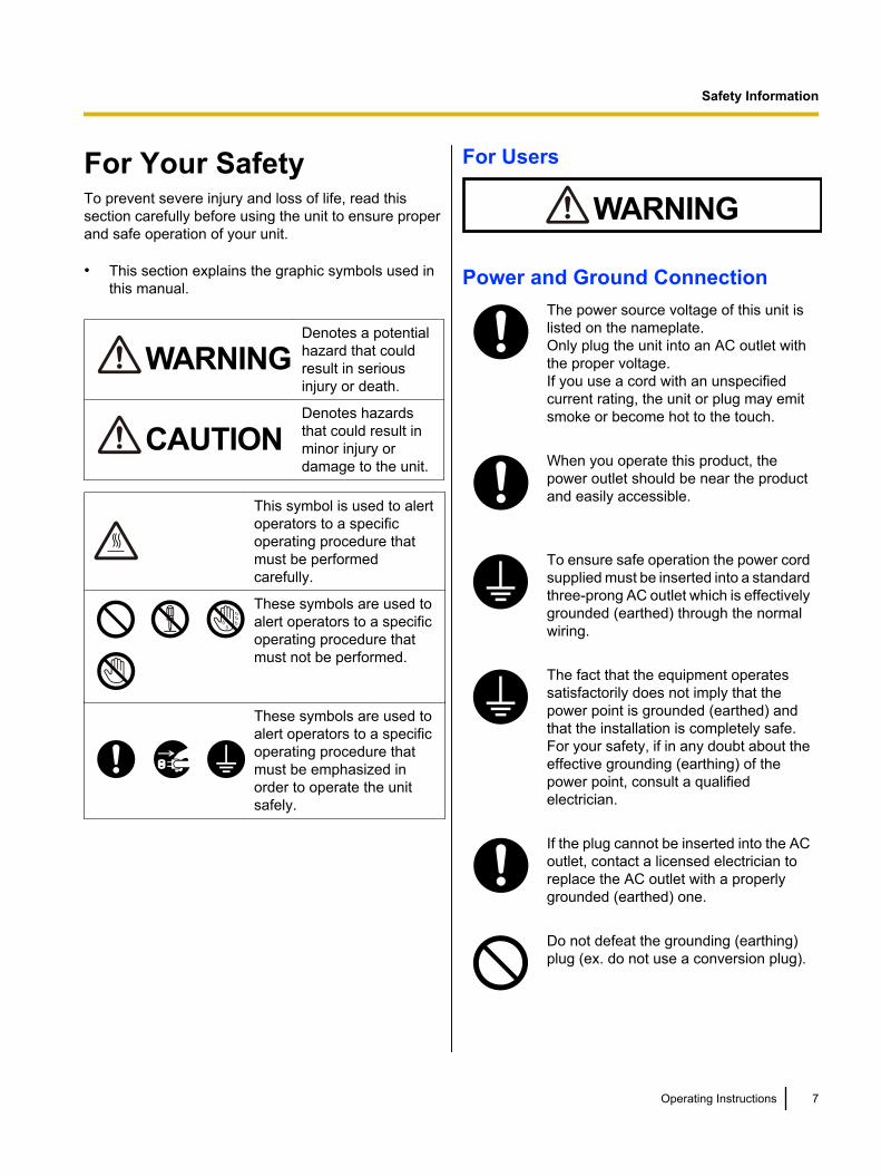
For Your SafetyTo prevent severe injury and loss of life, read thissection carefully before using the unit to ensure properand safe operation of your unit.
• This section explains the graphic symbols used inthis manual.
WARNINGDenotes a potentialhazard that couldresult in seriousinjury or death.
CAUTIONDenotes hazardsthat could result inminor injury ordamage to the unit.
This symbol is used to alertoperators to a specificoperating procedure thatmust be performedcarefully.
These symbols are used toalert operators to a specificoperating procedure thatmust not be performed.
These symbols are used toalert operators to a specificoperating procedure thatmust be emphasized inorder to operate the unitsafely.
For Users
WARNING
Power and Ground ConnectionThe power source voltage of this unit islisted on the nameplate.Only plug the unit into an AC outlet withthe proper voltage.If you use a cord with an unspecifiedcurrent rating, the unit or plug may emitsmoke or become hot to the touch.
When you operate this product, thepower outlet should be near the productand easily accessible.
To ensure safe operation the power cordsupplied must be inserted into a standardthree-prong AC outlet which is effectivelygrounded (earthed) through the normalwiring.
The fact that the equipment operatessatisfactorily does not imply that thepower point is grounded (earthed) andthat the installation is completely safe.For your safety, if in any doubt about theeffective grounding (earthing) of thepower point, consult a qualifiedelectrician.
If the plug cannot be inserted into the ACoutlet, contact a licensed electrician toreplace the AC outlet with a properlygrounded (earthed) one.
Do not defeat the grounding (earthing)plug (ex. do not use a conversion plug).
Operating Instructions 7
Safety Information
Safety Information
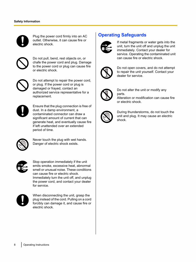
Plug the power cord firmly into an ACoutlet. Otherwise, it can cause fire orelectric shock.
Do not pull, bend, rest objects on, orchafe the power cord and plug. Damageto the power cord or plug can cause fireor electric shock.
Do not attempt to repair the power cord,or plug. If the power cord or plug isdamaged or frayed, contact anauthorized service representative for areplacement.
Ensure that the plug connection is free ofdust. In a damp environment, acontaminated connector can draw asignificant amount of current that cangenerate heat, and eventually cause fireif left unattended over an extendedperiod of time.
Never touch the plug with wet hands.Danger of electric shock exists.
Stop operation immediately if the unitemits smoke, excessive heat, abnormalsmell or unusual noise. These conditionscan cause fire or electric shock.Immediately turn the unit off, and unplugthe power cord, and contact your dealerfor service.
When disconnecting the unit, grasp theplug instead of the cord. Pulling on a cordforcibly can damage it, and cause fire orelectric shock.
Operating SafeguardsIf metal fragments or water gets into theunit, turn the unit off and unplug the unitimmediately. Contact your dealer forservice. Operating the contaminated unitcan cause fire or electric shock.
Do not open covers, and do not attemptto repair the unit yourself. Contact yourdealer for service.
Do not alter the unit or modify anyparts.Alteration or modification can cause fireor electric shock.
During thunderstorms, do not touch theunit and plug. It may cause an electricshock.
8 Operating Instructions
Safety Information
CAUTION
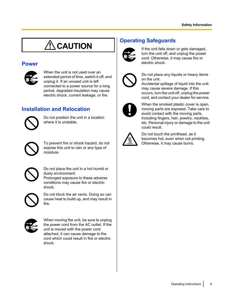
PowerWhen the unit is not used over anextended period of time, switch it off, andunplug it. If an unused unit is leftconnected to a power source for a longperiod, degraded insulation may causeelectric shock, current leakage, or fire.
Installation and RelocationDo not position the unit in a locationwhere it is unstable.
To prevent fire or shock hazard, do notexpose this unit to rain or any type ofmoisture.
Do not place the unit in a hot humid ordusty environment.Prolonged exposure to these adverseconditions may cause fire or electricshock.
Do not block the air vents. Doing so cancause heat to build up, and may result infire.
When moving the unit, be sure to unplugthe power cord from the AC outlet. If theunit is moved with the power cordattached, it can cause damage to thecord which could result in fire or electricshock.
Operating SafeguardsIf the unit falls down or gets damaged,turn the unit off, and unplug the powercord. Otherwise, it may cause fire orelectric shock.
Do not place any liquids or heavy itemson the unit.Accidental spillage of liquid into the unitmay cause severe damage. If thisoccurs, turn the unit off, unplug the powercord, and contact your dealer for service.
When the smoked plastic cover is open,moving parts are exposed. Take care toavoid contact with the moving parts,including fingers, hair, jewelry, neckties,etc. Personal injury or damage to the unitcould result.
Do not touch the printhead, as itbecomes hot, even when not printing.Otherwise, it may cause burns.
Operating Instructions 9
Safety Information
PrecautionsInstallation• Do not place the unit in direct sunlight and near hot
equipment.• The unit should not be exposed to extremely high
or low temperatures [temperature range: 10 °C to35 °C (50 °F to 95 °F)].
• The unit should not be exposed to extremely highor low humidity (humidity range: 30 % to 80 % RH).
• Avoid condensation resulting from rapid changes intemperature.
• Do not place the unit in areas with poor ventilation.• Do not place the unit in areas with high
concentrations of dust or chemical fumes, solvents,etc.
• Do not place books, paper or other items on top ofthe printer.
Operation• Do not operate the printer without installing paper
and a ribbon cassette.• Do not obstruct printhead movement while the
printer is operating.• Protect the unit from static electricity.
CD-ROM• Do not write or stick paper on the front and/or back
of CD-ROM.• Do not touch the data side of the CD-ROM. When
handling the CD-ROM, be careful not to leavefingerprints or otherwise damage the CD-ROM.
• Do not leave the CD-ROM where it is directlyexposed to sunlight or near a heater for extendedperiods.
• Do not throw or bend the CD-ROM.
Ink Ribbon• Do not store the ink ribbon in direct sunlight or in a
place with a temperature over 35 °C (95 °F).• For details about the ink ribbon, please refer to the
Material Safety Data Sheet (MSDS).Please ask your Panasonic sales company aboutobtaining the Material Safety Data Sheet.
Others• Do not use thinner, benzine, or cleaners containing
abrasives or surfactants, for cleaning the outside ofprinter.
• Plug the power cord into an outlet form which youcan easily unplug it.
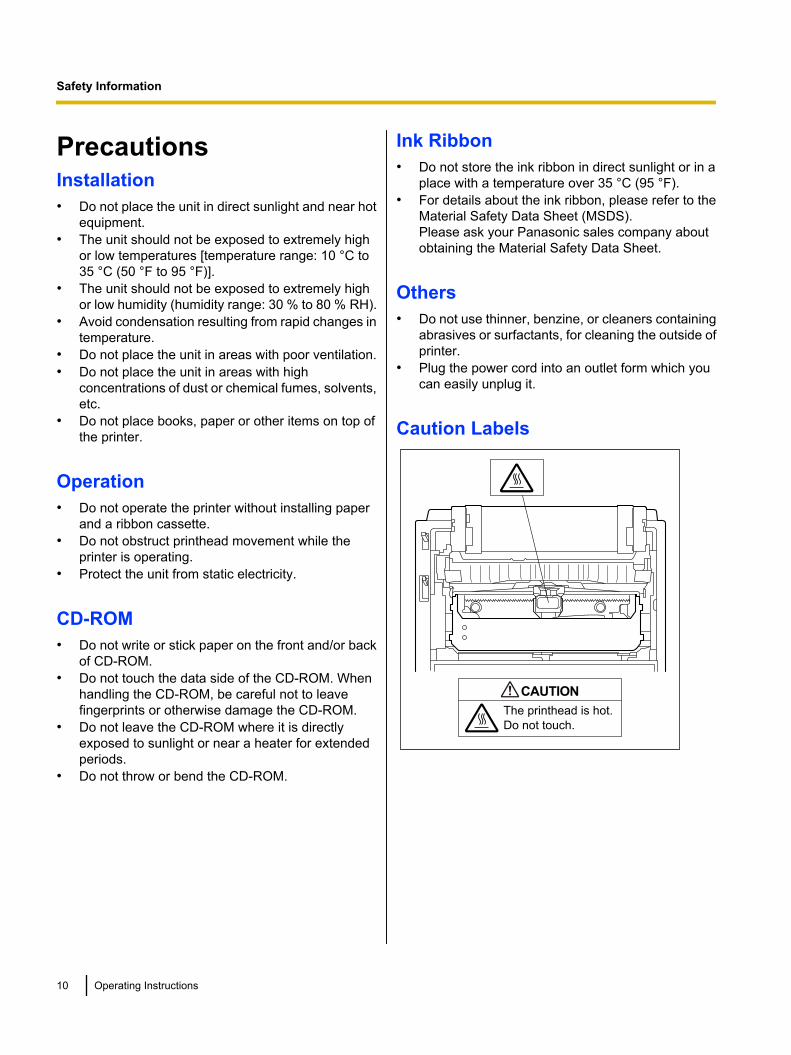
Caution Labels
The printhead is hot.
Do not touch.
CAUTION
10 Operating Instructions
Safety Information
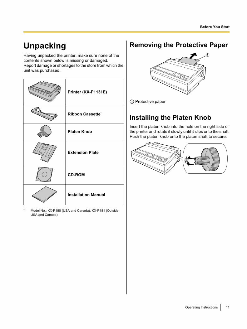
UnpackingHaving unpacked the printer, make sure none of thecontents shown below is missing or damaged.Report damage or shortages to the store from which theunit was purchased.
Printer (KX-P1131E)
Ribbon Cassette*1
Platen Knob
Extension Plate
CD-ROM
Installation Manual
*1 Model No.: KX-P180 (USA and Canada), KX-P181 (OutsideUSA and Canada)
Removing the Protective PaperA
A Protective paper
Installing the Platen KnobInsert the platen knob into the hole on the right side ofthe printer and rotate it slowly until it slips onto the shaft.Push the platen knob onto the platen shaft to secure.
Operating Instructions 11
Before You Start
Before You Start
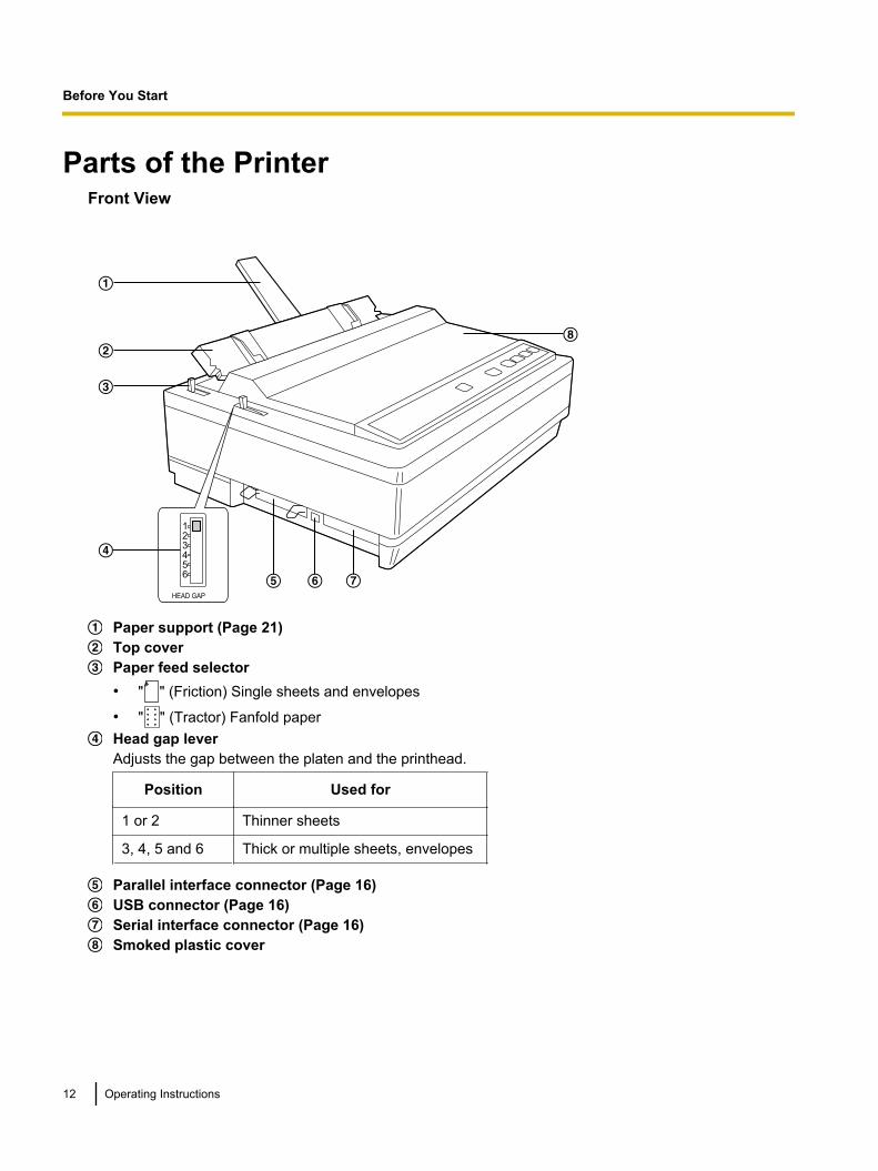
Parts of the PrinterFront View
A
B
C
E F G
H
HEAD GAP
D
Paper support (Page 21)Top coverPaper feed selector• " " (Friction) Single sheets and envelopes
• " " (Tractor) Fanfold paperHead gap leverAdjusts the gap between the platen and the printhead.
Position Used for
1 or 2 Thinner sheets
3, 4, 5 and 6 Thick or multiple sheets, envelopes
Parallel interface connector (Page 16)USB connector (Page 16)Serial interface connector (Page 16)Smoked plastic cover
12 Operating Instructions
Before You Start
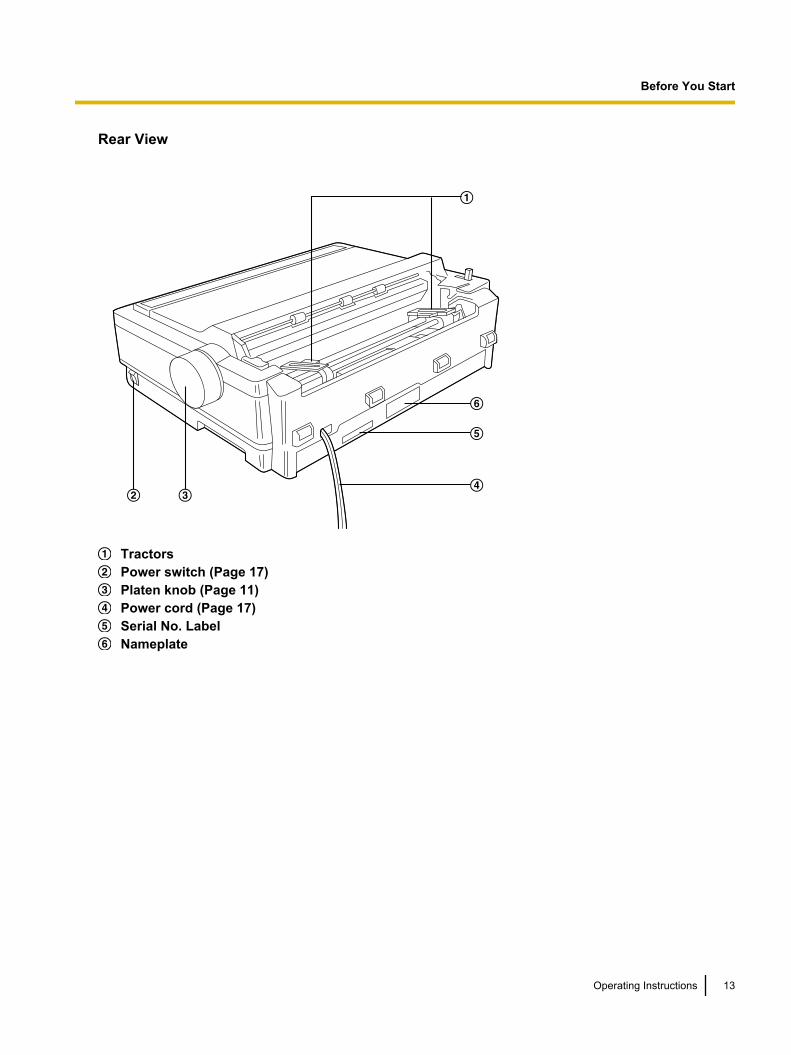
Rear View
A
B CD
E
F
TractorsPower switch (Page 17)Platen knob (Page 11)Power cord (Page 17)Serial No. LabelNameplate
Operating Instructions 13
Before You Start
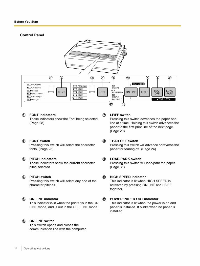
Control Panel
BA C D E F G H
J K
I
A FONT indicatorsThese indicators show the Font being selected.(Page 28)
G LF/FF switchPressing this switch advances the paper oneline at a time. Holding this switch advances thepaper to the first print line of the next page.(Page 29)
B FONT switchPressing this switch will select the characterfonts. (Page 28)
H TEAR OFF switchPressing this switch will advance or reverse thepaper for tearing off. (Page 24)
C PITCH indicatorsThese indicators show the current characterpitch selected.
I LOAD/PARK switchPressing this switch will load/park the paper.(Page 31)
D PITCH switchPressing this switch will select any one of thecharacter pitches.
J HIGH SPEED indicatorThis indicator is lit when HIGH SPEED isactivated by pressing ONLINE and LF/FFtogether.
E ON LINE indicatorThis indicator is lit when the printer is in the ONLINE mode, and is out in the OFF LINE mode.
K POWER/PAPER OUT indicatorThis indicator is lit when the power is on andpaper is installed. It blinks when no paper isinstalled.
F ON LINE switchThis switch opens and closes thecommunication line with the computer.
14 Operating Instructions
Before You Start
Installing the Software
System RequirementsComputer IBM PC/AT® or compatible machine
with a CD-ROM drive
OperatingSystem
Windows 2000 / Windows XP /Windows Vista / Windows 7
Interface USB 2.0 Full speed, Centronicsparallel (IEEE1284 standard), RS-232C serial
Software InstallationThe software on the enclosed CD-ROM can be installedon your computer.
Notice• Make sure to install the software before
connecting your computer to the printer.
1. Turn on your computer and start Windowsoperating system.• Log into an account with Administrator
privileges.2. Insert the included CD-ROM into the CD-ROM
drive.• The setup screen will be displayed.• If the setup screen does not appear, select your
CD-ROM drive in Explorer and double-click[CDRun.exe].
• In Windows Vista and Windows 7, if theAutoplay dialog box is displayed, click [RunCDRun.exe].
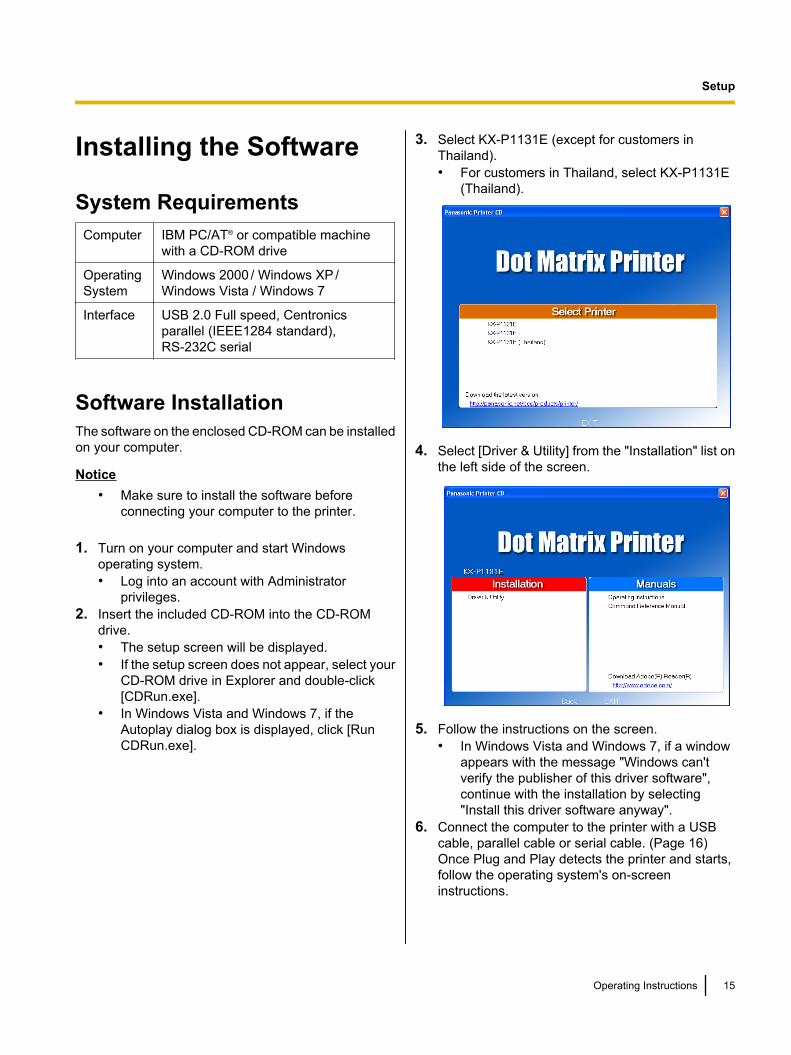
3. Select KX-P1131E (except for customers inThailand).• For customers in Thailand, select KX-P1131E
(Thailand).
4. Select [Driver & Utility] from the "Installation" list onthe left side of the screen.
5. Follow the instructions on the screen.• In Windows Vista and Windows 7, if a window
appears with the message "Windows can'tverify the publisher of this driver software",continue with the installation by selecting"Install this driver software anyway".
6. Connect the computer to the printer with a USBcable, parallel cable or serial cable. (Page 16)Once Plug and Play detects the printer and starts,follow the operating system's on-screeninstructions.
Operating Instructions 15
Setup
Setup
Connecting to aComputerBefore you connect the printer for the first time,install the USB and Printer driver on to yourcomputer. For more information see "Installing theSoftware (Page 15)".
Note• If you do not have a USB cable, parallel
interface cable or serial interface cable, you willneed to purchase one or contact your dealer.
1. Turn off the power switch of both the printer andthe computer.
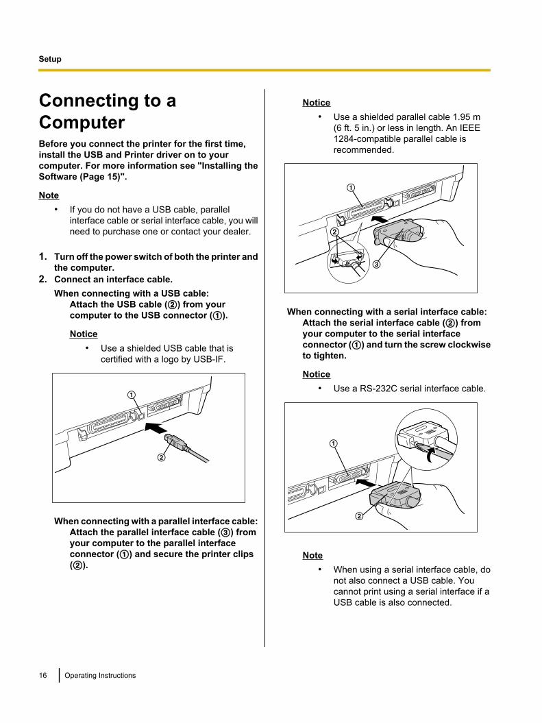
2. Connect an interface cable.When connecting with a USB cable:
Attach the USB cable (B) from yourcomputer to the USB connector (A).
Notice• Use a shielded USB cable that is
certified with a logo by USB-IF.
A
B
When connecting with a parallel interface cable:Attach the parallel interface cable (C) fromyour computer to the parallel interfaceconnector (A) and secure the printer clips(B).
Notice• Use a shielded parallel cable 1.95 m
(6 ft. 5 in.) or less in length. An IEEE1284-compatible parallel cable isrecommended.
A
C
BBB
When connecting with a serial interface cable:Attach the serial interface cable (B) fromyour computer to the serial interfaceconnector (A) and turn the screw clockwiseto tighten.
Notice• Use a RS-232C serial interface cable.
B
A
Note• When using a serial interface cable, do
not also connect a USB cable. Youcannot print using a serial interface if aUSB cable is also connected.
16 Operating Instructions
Setup
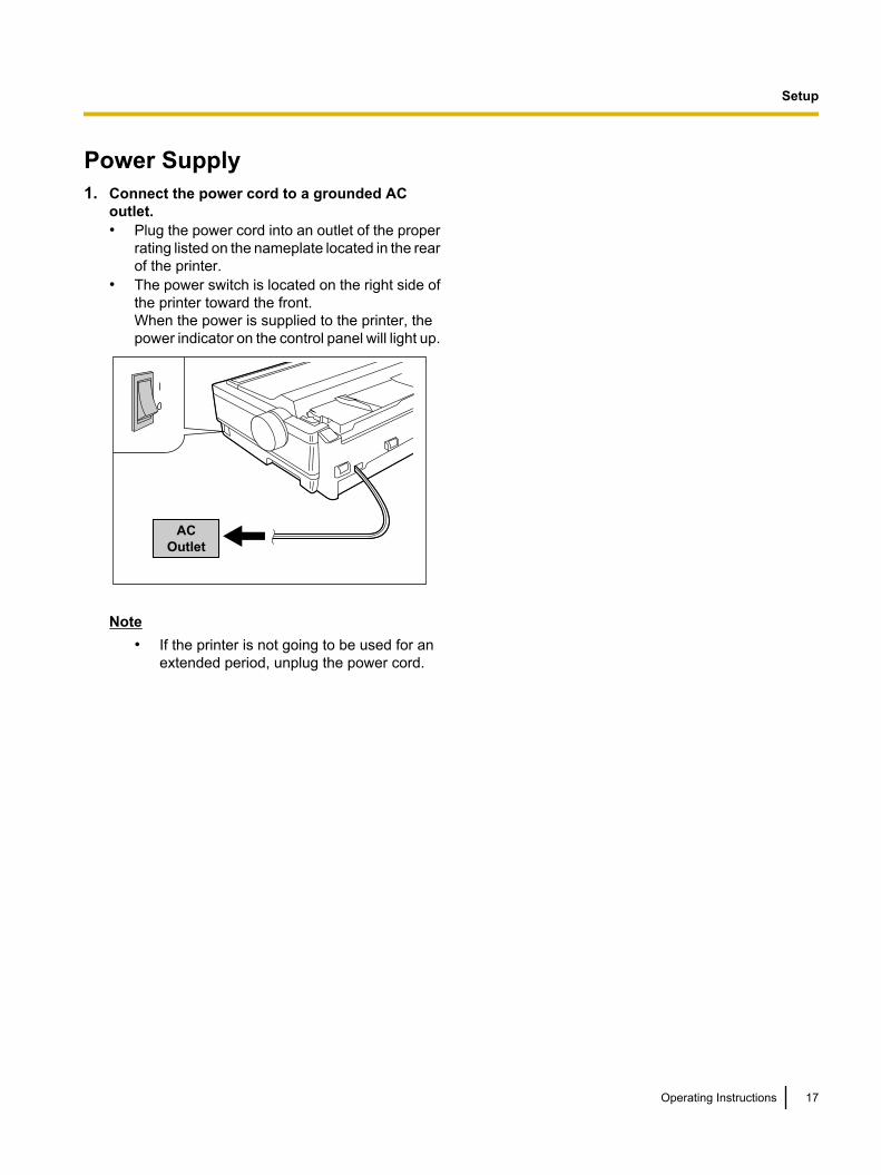
Power Supply1. Connect the power cord to a grounded AC
outlet.• Plug the power cord into an outlet of the proper
rating listed on the nameplate located in the rearof the printer.
• The power switch is located on the right side ofthe printer toward the front.When the power is supplied to the printer, thepower indicator on the control panel will light up.
AC
Outlet
Note• If the printer is not going to be used for an
extended period, unplug the power cord.
Operating Instructions 17
Setup
Installing the RibbonCassette
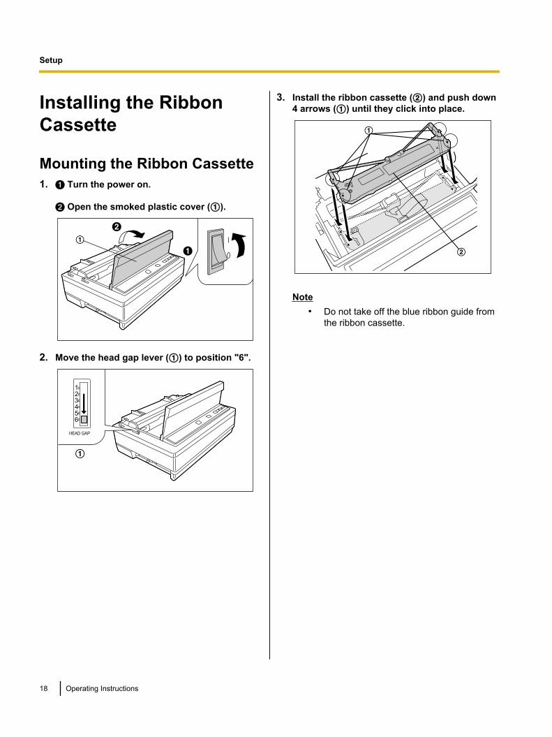
Mounting the Ribbon Cassette1. A Turn the power on.
B Open the smoked plastic cover (A).
A
A
B
2. Move the head gap lever (A) to position "6".
HEAD GAP
A
3. Install the ribbon cassette (B) and push down4 arrows (A) until they click into place.
A
B
Note• Do not take off the blue ribbon guide from
the ribbon cassette.
18 Operating Instructions
Setup
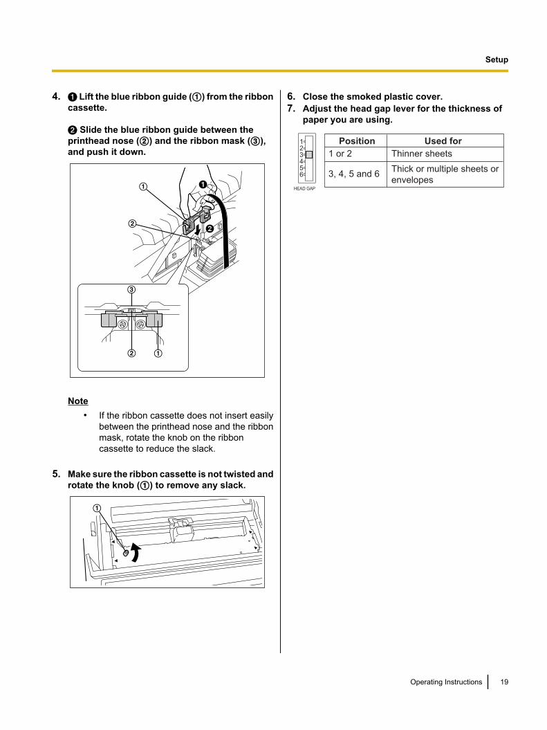
4. A Lift the blue ribbon guide (A) from the ribboncassette.
B Slide the blue ribbon guide between theprinthead nose (B) and the ribbon mask (C),and push it down.
A A
B
A
B
A
B
C
B
Note• If the ribbon cassette does not insert easily
between the printhead nose and the ribbonmask, rotate the knob on the ribboncassette to reduce the slack.
5. Make sure the ribbon cassette is not twisted androtate the knob (A) to remove any slack.
A
6. Close the smoked plastic cover.7. Adjust the head gap lever for the thickness of
paper you are using.
HEAD GAP
Position Used for
1 or 2 Thinner sheets
3, 4, 5 and 6Thick or multiple sheets or
envelopes
Operating Instructions 19
Setup
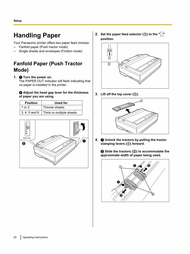
Handling PaperYour Panasonic printer offers two paper feed choices:– Fanfold paper (Push tractor mode)– Single sheets and envelopes (Friction mode)
Fanfold Paper (Push TractorMode)1. A Turn the power on.
The PAPER OUT indicator will flash indicating thatno paper is installed in the printer.
B Adjust the head gap lever for the thicknessof paper you are using.
Position Used for
1 or 2 Thinner sheets
3, 4, 5 and 6 Thick or multiple sheets
AB
HEAD GAP
2. Set the paper feed selector (A) to the " "position.
A
3. Lift off the top cover (A).
A
4. A Unlock the tractors by pulling the tractorclamping levers (A) forward.
B Slide the tractors (B) to accommodate theapproximate width of paper being used.
A A B
B
A
A B
B
A
B
20 Operating Instructions
Setup
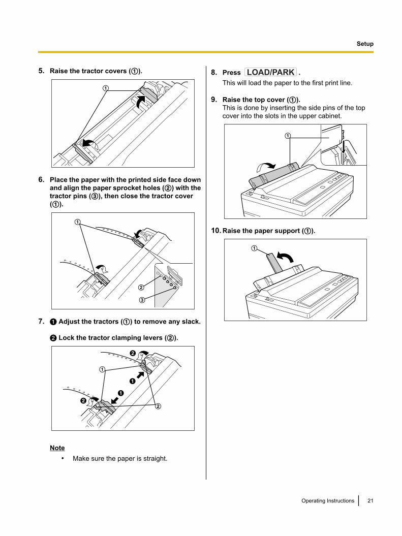
5. Raise the tractor covers (A).
A
6. Place the paper with the printed side face downand align the paper sprocket holes (B) with thetractor pins (C), then close the tractor cover(A).
A
B
C
7. A Adjust the tractors (A) to remove any slack.
B Lock the tractor clamping levers (B).
B
B
A
A
B
B
A
A
A
B
Note• Make sure the paper is straight.
8. Press LOAD/PARK .This will load the paper to the first print line.
9. Raise the top cover (A).This is done by inserting the side pins of the topcover into the slots in the upper cabinet.
A
10. Raise the paper support (A).
A
Operating Instructions 21
Setup
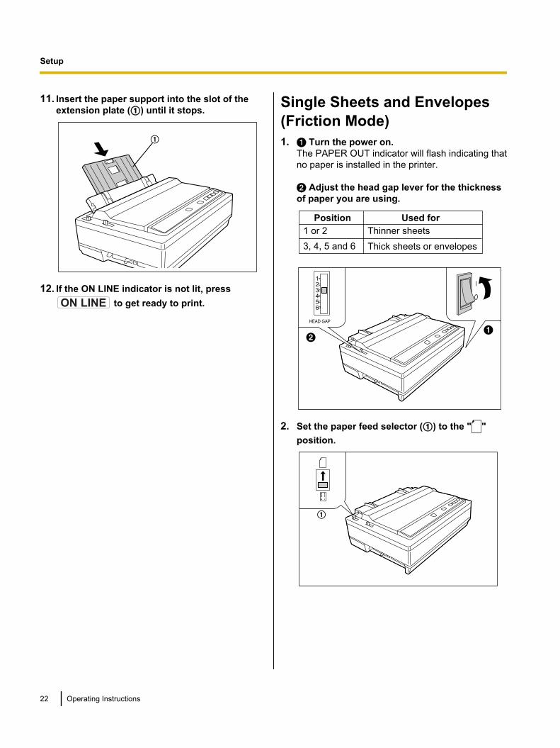
11. Insert the paper support into the slot of theextension plate (A) until it stops.
A
12. If the ON LINE indicator is not lit, pressON LINE to get ready to print.
Single Sheets and Envelopes(Friction Mode)1. A Turn the power on.
The PAPER OUT indicator will flash indicating thatno paper is installed in the printer.
B Adjust the head gap lever for the thicknessof paper you are using.
Position Used for
1 or 2 Thinner sheets
3, 4, 5 and 6 Thick sheets or envelopes
AB
HEAD GAP
2. Set the paper feed selector (A) to the " "position.
A
22 Operating Instructions
Setup
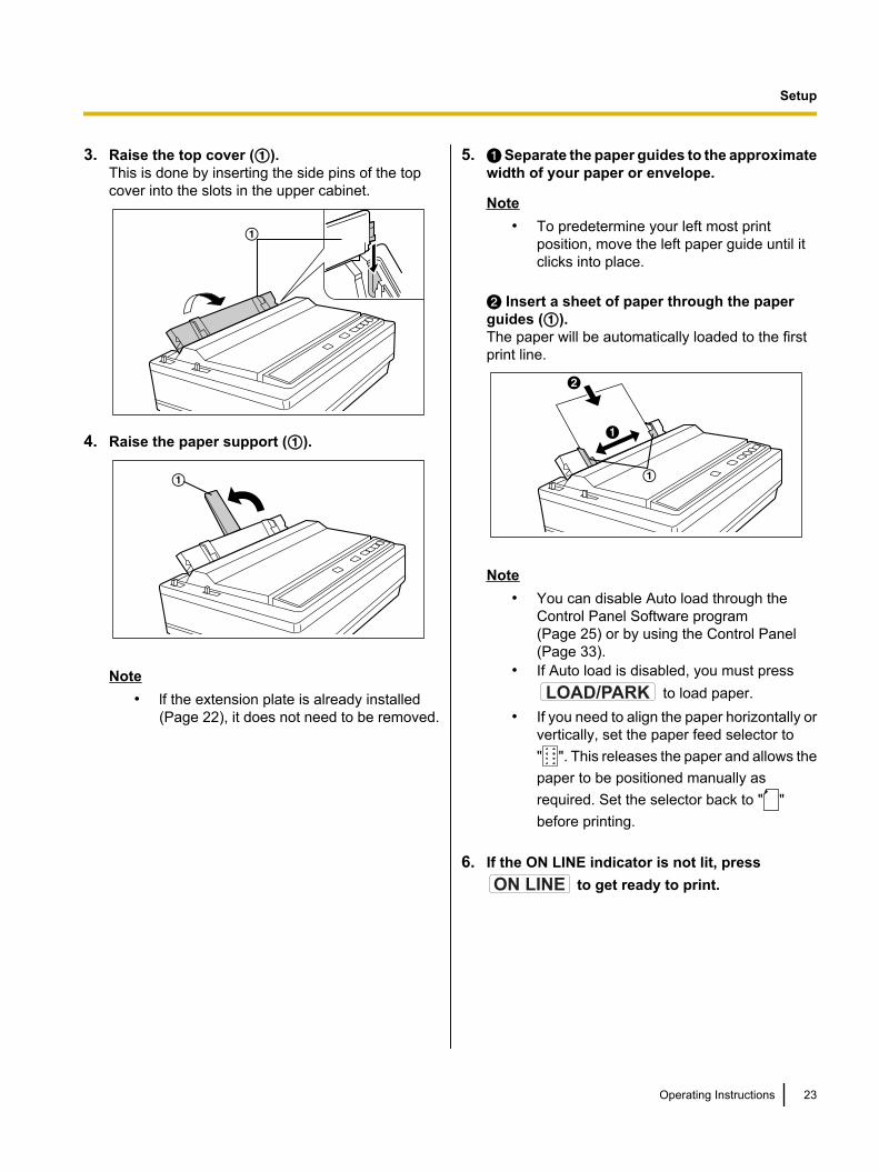
3. Raise the top cover (A).This is done by inserting the side pins of the topcover into the slots in the upper cabinet.
A
4. Raise the paper support (A).
A
Note• lf the extension plate is already installed
(Page 22), it does not need to be removed.
5. A Separate the paper guides to the approximatewidth of your paper or envelope.
Note• To predetermine your left most print
position, move the left paper guide until itclicks into place.
B Insert a sheet of paper through the paperguides (A).The paper will be automatically loaded to the firstprint line.
B
A
A
Note• You can disable Auto load through the
Control Panel Software program(Page 25) or by using the Control Panel(Page 33).
• If Auto load is disabled, you must pressLOAD/PARK to load paper.
• If you need to align the paper horizontally orvertically, set the paper feed selector to" ". This releases the paper and allows thepaper to be positioned manually asrequired. Set the selector back to " "before printing.
6. If the ON LINE indicator is not lit, pressON LINE to get ready to print.
Operating Instructions 23
Setup
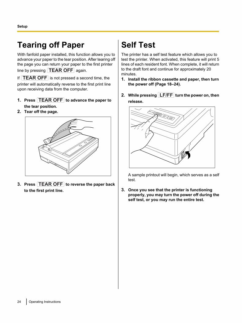
Tearing off PaperWith fanfold paper installed, this function allows you toadvance your paper to the tear position. After tearing offthe page you can return your paper to the first printerline by pressing TEAR OFF again.
If TEAR OFF is not pressed a second time, theprinter will automatically reverse to the first print lineupon receiving data from the computer.
1. Press TEAR OFF to advance the paper tothe tear position.
2. Tear off the page.
3. Press TEAR OFF to reverse the paper backto the first print line.
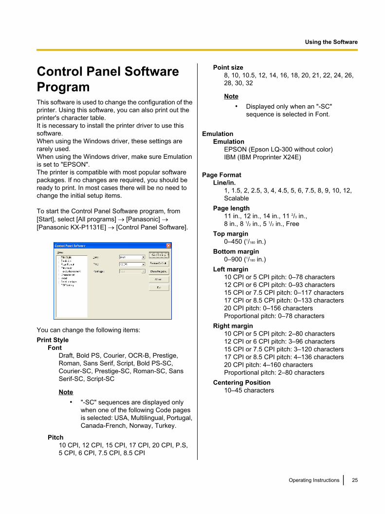
Self TestThe printer has a self test feature which allows you totest the printer. When activated, this feature will print 5lines of each resident font. When complete, it will returnto the draft font and continue for approximately 20minutes.1. Install the ribbon cassette and paper, then turn
the power off (Page 18–24).
2. While pressing LF/FF turn the power on, thenrelease.
A sample printout will begin, which serves as a selftest.
3. Once you see that the printer is functioningproperly, you may turn the power off during theself test, or you may run the entire test.
24 Operating Instructions
Setup
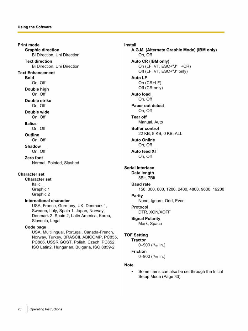
Control Panel SoftwareProgramThis software is used to change the configuration of theprinter. Using this software, you can also print out theprinter's character table.It is necessary to install the printer driver to use thissoftware.When using the Windows driver, these settings arerarely used.When using the Windows driver, make sure Emulationis set to "EPSON".The printer is compatible with most popular softwarepackages. If no changes are required, you should beready to print. In most cases there will be no need tochange the initial setup items.
To start the Control Panel Software program, from[Start], select [All programs] ® [Panasonic] ®[Panasonic KX-P1131E] ® [Control Panel Software].
You can change the following items:Print Style
FontDraft, Bold PS, Courier, OCR-B, Prestige,Roman, Sans Serif, Script, Bold PS-SC,Courier-SC, Prestige-SC, Roman-SC, SansSerif-SC, Script-SC
Note• "-SC" sequences are displayed only
when one of the following Code pagesis selected: USA, Multilingual, Portugal,Canada-French, Norway, Turkey.
Pitch10 CPI, 12 CPI, 15 CPI, 17 CPI, 20 CPI, P.S,5 CPI, 6 CPI, 7.5 CPI, 8.5 CPI
Point size8, 10, 10.5, 12, 14, 16, 18, 20, 21, 22, 24, 26,28, 30, 32
Note• Displayed only when an "-SC"
sequence is selected in Font.
EmulationEmulation
EPSON (Epson LQ-300 without color)IBM (IBM Proprinter X24E)
Page FormatLine/in.
1, 1.5, 2, 2.5, 3, 4, 4.5, 5, 6, 7.5, 8, 9, 10, 12,Scalable
Page length11 in., 12 in., 14 in., 11 2/3 in.,8 in., 8 1/2 in., 5 1/2 in., Free
Top margin0–450 (1/180 in.)
Bottom margin0–900 (1/180 in.)
Left margin10 CPI or 5 CPI pitch: 0–78 characters12 CPI or 6 CPI pitch: 0–93 characters15 CPI or 7.5 CPI pitch: 0–117 characters17 CPI or 8.5 CPI pitch: 0–133 characters20 CPI pitch: 0–156 charactersProportional pitch: 0–78 characters
Right margin10 CPI or 5 CPI pitch: 2–80 characters12 CPI or 6 CPI pitch: 3–96 characters15 CPI or 7.5 CPI pitch: 3–120 characters17 CPI or 8.5 CPI pitch: 4–136 characters20 CPI pitch: 4–160 charactersProportional pitch: 2–80 characters
Centering Position10–45 characters
Operating Instructions 25
Using the Software
Using the Software
Print modeGraphic direction
Bi Direction, Uni DirectionText direction
Bi Direction, Uni DirectionText Enhancement
BoldOn, Off
Double highOn, Off
Double strikeOn, Off
Double wideOn, Off
ItalicsOn, Off
OutlineOn, Off
ShadowOn, Off
Zero fontNormal, Pointed, Slashed
Character setCharacter set
ItalicGraphic 1Graphic 2
International characterUSA, France, Germany, UK, Denmark 1,Sweden, Italy, Spain 1, Japan, Norway,Denmark 2, Spain 2, Latin America, Korea,Slovenia, Legal
Code pageUSA, Multilingual, Portugal, Canada-French,Norway, Turkey, BRASCII, ABICOMP, PC855,PC866, USSR GOST, Polish, Czech, PC852,ISO Latin2, Hungarian, Bulgaria, ISO 8859-2
InstallA.G.M. (Alternate Graphic Mode) (IBM only)
On, OffAuto CR (IBM only)
On (LF, VT, ESC+"J" +CR)Off (LF, VT, ESC+"J" only)
Auto LFOn (CR+LF)Off (CR only)
Auto loadOn, Off
Paper out detectOn, Off
Tear offManual, Auto
Buffer control22 KB, 8 KB, 0 KB, ALL
Auto OnlineOn, Off
Auto feed XTOn, Off
Serial InterfaceData length
8Bit, 7BitBaud rate
150, 300, 600, 1200, 2400, 4800, 9600, 19200Parity
None, Ignore, Odd, EvenProtocol
DTR, XON/XOFFSignal Polarity
Mark, Space
TOF SettingTractor
0–900 (1/180 in.)Friction
0–900 (1/180 in.)
Note• Some items can also be set through the Initial
Setup Mode (Page 33).
26 Operating Instructions
Using the Software
About the buttonsSend Settings
Sends the settings to the printer.Restore Default
Returns the settings to default.After pressing this button, the screen to select yourcountry is displayed. Select your country. If yourcountry is not displayed here, select [Othercountry].
Character TablePrints out the character table of the built-in font inthe printer.After pressing this button, the screen to select theemulation and character table is displayed.Select the desired table.
AboutDisplays the version of the software.
ExitExits the software.
Note• The screen to select your country is only
displayed when activating the software for thefirst time. When you activate the software fromthe second time, the screen to select yourcountry is not displayed.
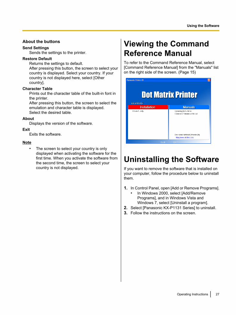
Viewing the CommandReference ManualTo refer to the Command Reference Manual, select[Command Reference Manual] from the "Manuals" liston the right side of the screen. (Page 15)
Uninstalling the SoftwareIf you want to remove the software that is installed onyour computer, follow the procedure below to uninstallthem.
1. In Control Panel, open [Add or Remove Programs].• In Windows 2000, select [Add/Remove
Programs], and in Windows Vista andWindows 7, select [Uninstall a program].
2. Select [Panasonic KX-P1131 Series] to uninstall.3. Follow the instructions on the screen.
Operating Instructions 27
Using the Software
Using the Control Panel
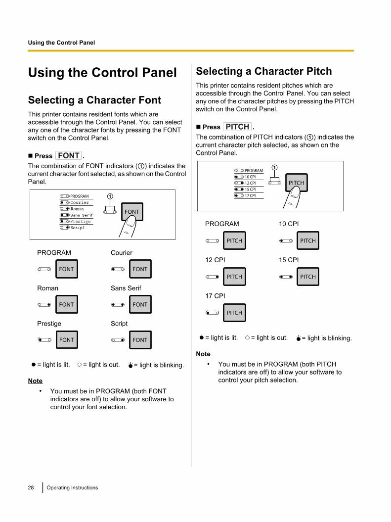
Selecting a Character FontThis printer contains resident fonts which areaccessible through the Control Panel. You can selectany one of the character fonts by pressing the FONTswitch on the Control Panel.
n Press FONT .The combination of FONT indicators (A) indicates thecurrent character font selected, as shown on the ControlPanel.
A
PROGRAM Courier
Roman Sans Serif
Prestige Script
= light is lit. = light is out. = light is blinking.
Note• You must be in PROGRAM (both FONT
indicators are off) to allow your software tocontrol your font selection.
Selecting a Character PitchThis printer contains resident pitches which areaccessible through the Control Panel. You can selectany one of the character pitches by pressing the PITCHswitch on the Control Panel.
n Press PITCH .The combination of PITCH indicators (A) indicates thecurrent character pitch selected, as shown on theControl Panel.
A
PROGRAM 10 CPI
12 CPI 15 CPI
17 CPI
= light is lit. = light is out. = light is blinking.
Note• You must be in PROGRAM (both PITCH
indicators are off) to allow your software tocontrol your pitch selection.
28 Operating Instructions
Using the Control Panel
Using the Control Panel
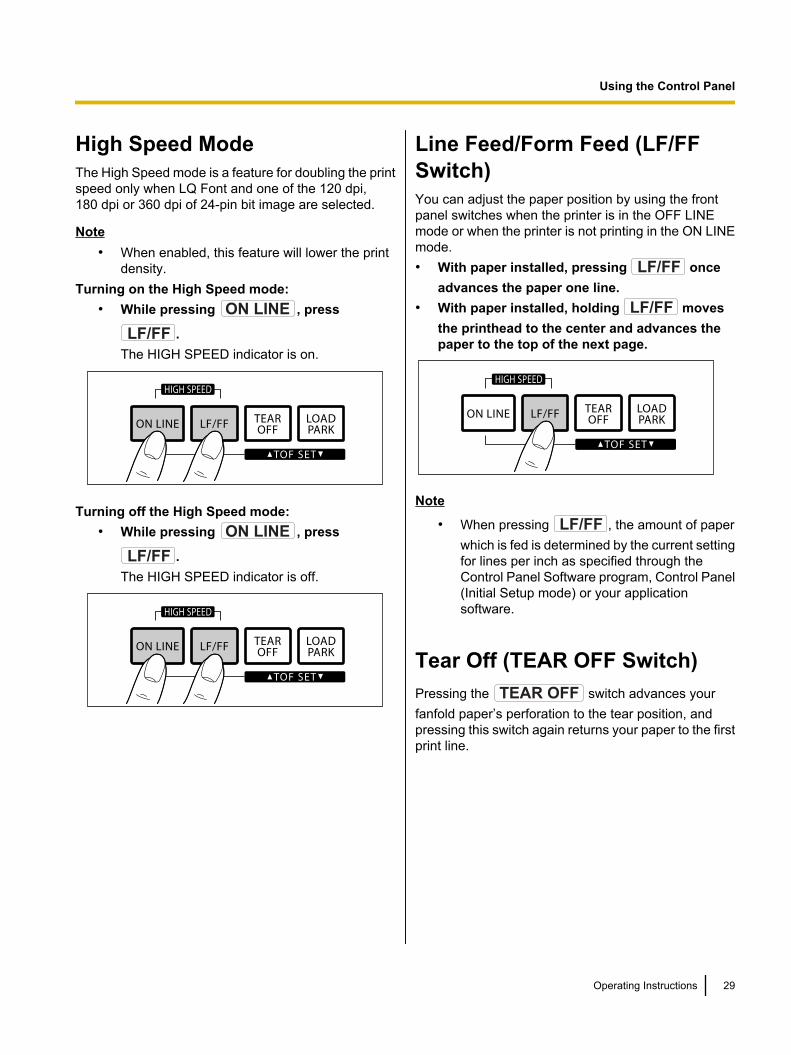
High Speed ModeThe High Speed mode is a feature for doubling the printspeed only when LQ Font and one of the 120 dpi,180 dpi or 360 dpi of 24-pin bit image are selected.
Note• When enabled, this feature will lower the print
density.Turning on the High Speed mode:
• While pressing ON LINE , press
LF/FF .The HIGH SPEED indicator is on.
Turning off the High Speed mode:• While pressing ON LINE , press
LF/FF .The HIGH SPEED indicator is off.
Line Feed/Form Feed (LF/FFSwitch)You can adjust the paper position by using the frontpanel switches when the printer is in the OFF LINEmode or when the printer is not printing in the ON LINEmode.• With paper installed, pressing LF/FF once
advances the paper one line.• With paper installed, holding LF/FF moves
the printhead to the center and advances thepaper to the top of the next page.
Note
• When pressing LF/FF , the amount of paperwhich is fed is determined by the current settingfor lines per inch as specified through theControl Panel Software program, Control Panel(Initial Setup mode) or your applicationsoftware.
Tear Off (TEAR OFF Switch)Pressing the TEAR OFF switch advances yourfanfold paper’s perforation to the tear position, andpressing this switch again returns your paper to the firstprint line.
Operating Instructions 29
Using the Control Panel
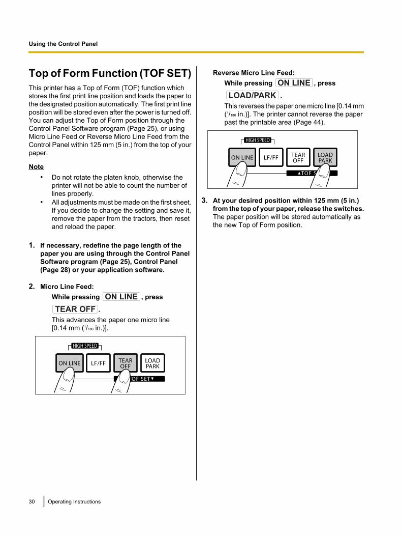
Top of Form Function (TOF SET)This printer has a Top of Form (TOF) function whichstores the first print line position and loads the paper tothe designated position automatically. The first print lineposition will be stored even after the power is turned off.You can adjust the Top of Form position through theControl Panel Software program (Page 25), or usingMicro Line Feed or Reverse Micro Line Feed from theControl Panel within 125 mm (5 in.) from the top of yourpaper.
Note• Do not rotate the platen knob, otherwise the
printer will not be able to count the number oflines properly.
• All adjustments must be made on the first sheet.If you decide to change the setting and save it,remove the paper from the tractors, then resetand reload the paper.
1. If necessary, redefine the page length of thepaper you are using through the Control PanelSoftware program (Page 25), Control Panel(Page 28) or your application software.
2. Micro Line Feed:While pressing ON LINE , press
TEAR OFF .This advances the paper one micro line[0.14 mm (1/180 in.)].
Reverse Micro Line Feed:While pressing ON LINE , press
LOAD/PARK .This reverses the paper one micro line [0.14 mm(1/180 in.)]. The printer cannot reverse the paperpast the printable area (Page 44).
3. At your desired position within 125 mm (5 in.)from the top of your paper, release the switches.The paper position will be stored automatically asthe new Top of Form position.
30 Operating Instructions
Using the Control Panel
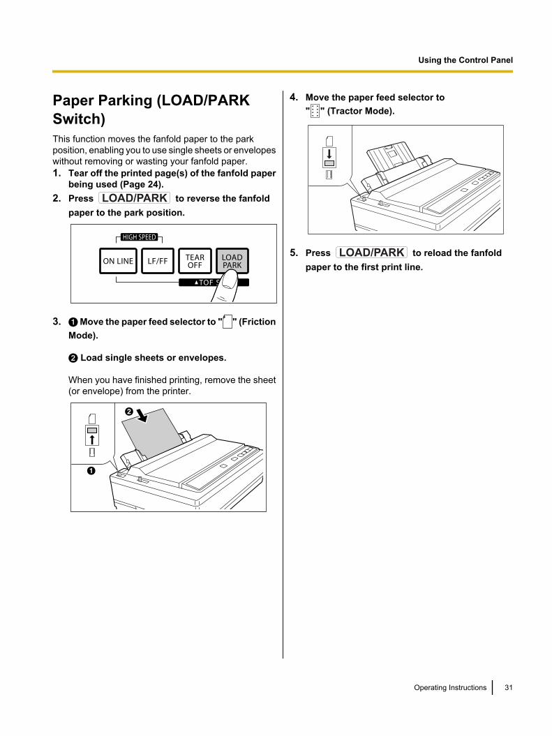
Paper Parking (LOAD/PARKSwitch)This function moves the fanfold paper to the parkposition, enabling you to use single sheets or envelopeswithout removing or wasting your fanfold paper.1. Tear off the printed page(s) of the fanfold paper
being used (Page 24).2. Press LOAD/PARK to reverse the fanfold
paper to the park position.
3. A Move the paper feed selector to " " (FrictionMode).
B Load single sheets or envelopes.
When you have finished printing, remove the sheet(or envelope) from the printer.
A
B
4. Move the paper feed selector to" " (Tractor Mode).
5. Press LOAD/PARK to reload the fanfoldpaper to the first print line.
Operating Instructions 31
Using the Control Panel
Paper Out DetectorYour printer has a paper out detector. When an out ofpaper condition occurs, printing stops, the printer goesto the OFF LINE mode, and the POWER/PAPER OUTindicator starts blinking. To continue printing to the endof the current page, follow the steps below.1. Press ON LINE repeatedly until the page is
completed.2. Insert the new paper (Page 20).3. If the ON LINE indicator is not lit, press
ON LINE .
Note• When Paper out detect is set to ON
(Page 34), printing stops at 1.26 mm (0.5 in.)from the bottom of the paper.
• The paper out detector can be disabled throughthe Control Panel Software program (Page 25).
32 Operating Instructions
Using the Control Panel
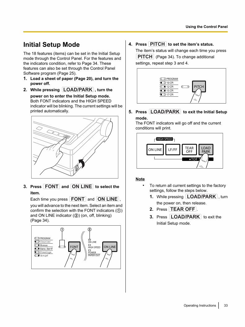
Initial Setup ModeThe 18 features (items) can be set in the Initial Setupmode through the Control Panel. For the features andthe indicators condition, refer to Page 34. Thesefeatures can also be set through the Control PanelSoftware program (Page 25).1. Load a sheet of paper (Page 20), and turn the
power off.2. While pressing LOAD/PARK , turn the
power on to enter the Initial Setup mode.Both FONT indicators and the HIGH SPEEDindicator will be blinking. The current settings will beprinted automatically.
3. Press FONT and ON LINE to select theitem.Each time you press FONT and ON LINE ,you will advance to the next item. Select an item andconfirm the selection with the FONT indicators (A)and ON LINE indicator (B) (on, off, blinking)(Page 34).
A B
4. Press PITCH to set the item’s status.The item’s status will change each time you pressPITCH (Page 34). To change additional
settings, repeat step 3 and 4.
5. Press LOAD/PARK to exit the Initial Setupmode.The FONT indicators will go off and the currentconditions will print.
Note• To return all current settings to the factory
settings, follow the steps below.1. While pressing LOAD/PARK , turn
the power on, then release.2. Press TEAR OFF .
3. Press LOAD/PARK to exit theInitial Setup mode.
Operating Instructions 33
Using the Control Panel
Control Panel
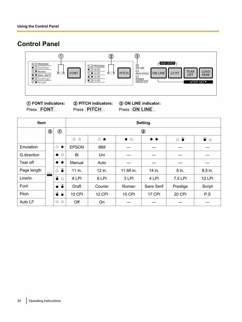
A B C
A FONT indicators:Press FONT .
B PITCH indicators:Press PITCH .
C ON LINE indicator:Press ON LINE .
Item Setting
C A B
Emulation EPSON IBM — — — —
G.direction Bi Uni — — — —
Tear off Manual Auto — — — —
Page length 11 in. 12 in. 11.66 in. 14 in. 8 in. 8.5 in.
Line/in. 6 LPI 8 LPI 3 LPI 4 LPI 7.5 LPI 12 LPI
Font Draft Courier Roman Sans Serif Prestige Script
Pitch 10 CPI 12 CPI 15 CPI 17 CPI 20 CPI P.S
Auto LF Off On — — — —
34 Operating Instructions
Using the Control Panel
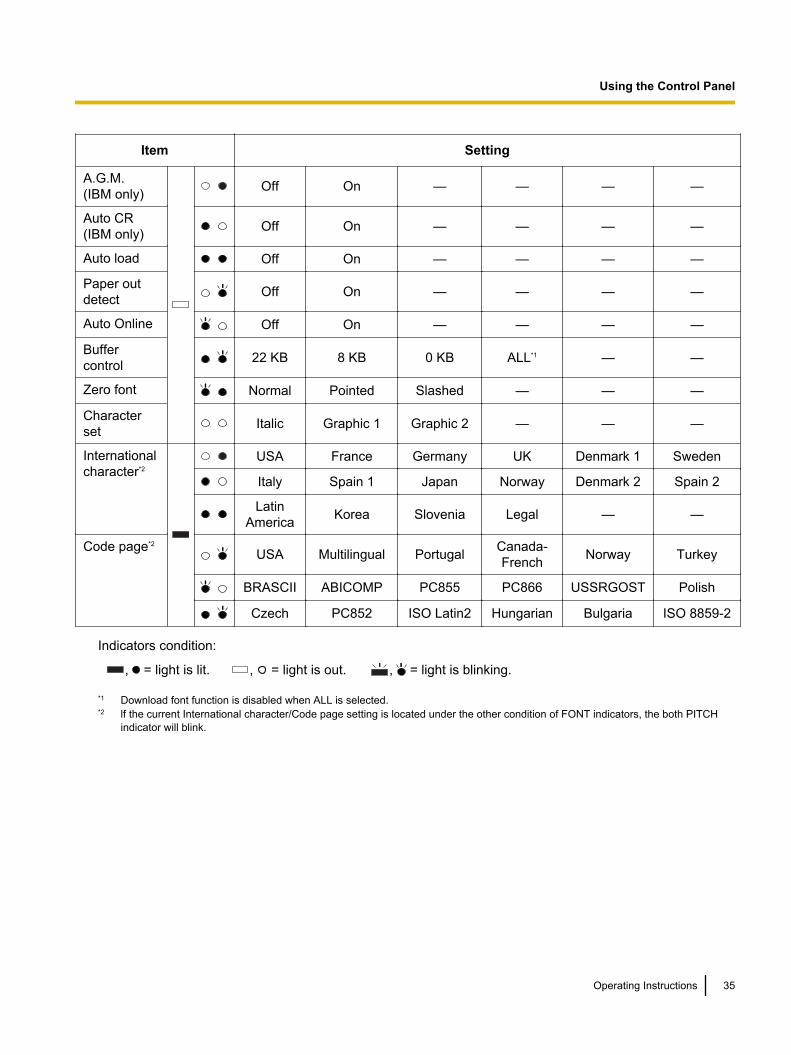
Item Setting
A.G.M.(IBM only) Off On — — — —
Auto CR(IBM only) Off On — — — —
Auto load Off On — — — —
Paper outdetect Off On — — — —
Auto Online Off On — — — —
Buffercontrol 22 KB 8 KB 0 KB ALL*1 — —
Zero font Normal Pointed Slashed — — —
Characterset Italic Graphic 1 Graphic 2 — — —
Internationalcharacter*2
USA France Germany UK Denmark 1 Sweden
Italy Spain 1 Japan Norway Denmark 2 Spain 2
LatinAmerica Korea Slovenia Legal — —
Code page*2
USA Multilingual Portugal Canada-French Norway Turkey
BRASCII ABICOMP PC855 PC866 USSRGOST Polish
Czech PC852 ISO Latin2 Hungarian Bulgaria ISO 8859-2
Indicators condition:
, = light is lit. , = light is out. , = light is blinking.
*1 Download font function is disabled when ALL is selected.*2 lf the current International character/Code page setting is located under the other condition of FONT indicators, the both PITCH
indicator will blink.
Operating Instructions 35
Using the Control Panel
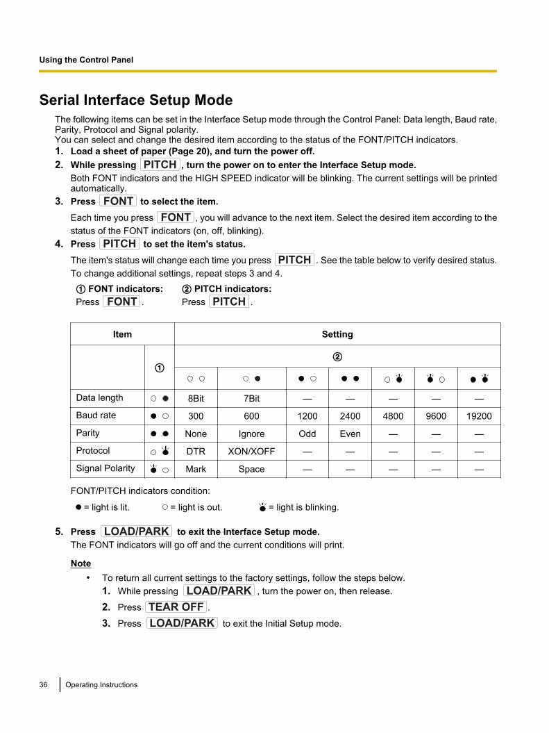
Serial Interface Setup ModeThe following items can be set in the Interface Setup mode through the Control Panel: Data length, Baud rate,Parity, Protocol and Signal polarity.You can select and change the desired item according to the status of the FONT/PITCH indicators.1. Load a sheet of paper (Page 20), and turn the power off.2. While pressing PITCH , turn the power on to enter the Interface Setup mode.
Both FONT indicators and the HIGH SPEED indicator will be blinking. The current settings will be printedautomatically.
3. Press FONT to select the item.
Each time you press FONT , you will advance to the next item. Select the desired item according to thestatus of the FONT indicators (on, off, blinking).
4. Press PITCH to set the item's status.
The item's status will change each time you press PITCH . See the table below to verify desired status.To change additional settings, repeat steps 3 and 4.
A FONT indicators:Press FONT .
B PITCH indicators:Press PITCH .
Item Setting
AB
Data length 8Bit 7Bit — — — — —
Baud rate 300 600 1200 2400 4800 9600 19200
Parity None Ignore Odd Even — — —
Protocol DTR XON/XOFF — — — — —
Signal Polarity Mark Space — — — — —
FONT/PITCH indicators condition:
= light is lit. = light is out. = light is blinking.
5. Press LOAD/PARK to exit the Interface Setup mode.The FONT indicators will go off and the current conditions will print.
Note• To return all current settings to the factory settings, follow the steps below.
1. While pressing LOAD/PARK , turn the power on, then release.
2. Press TEAR OFF .
3. Press LOAD/PARK to exit the Initial Setup mode.
36 Operating Instructions
Using the Control Panel
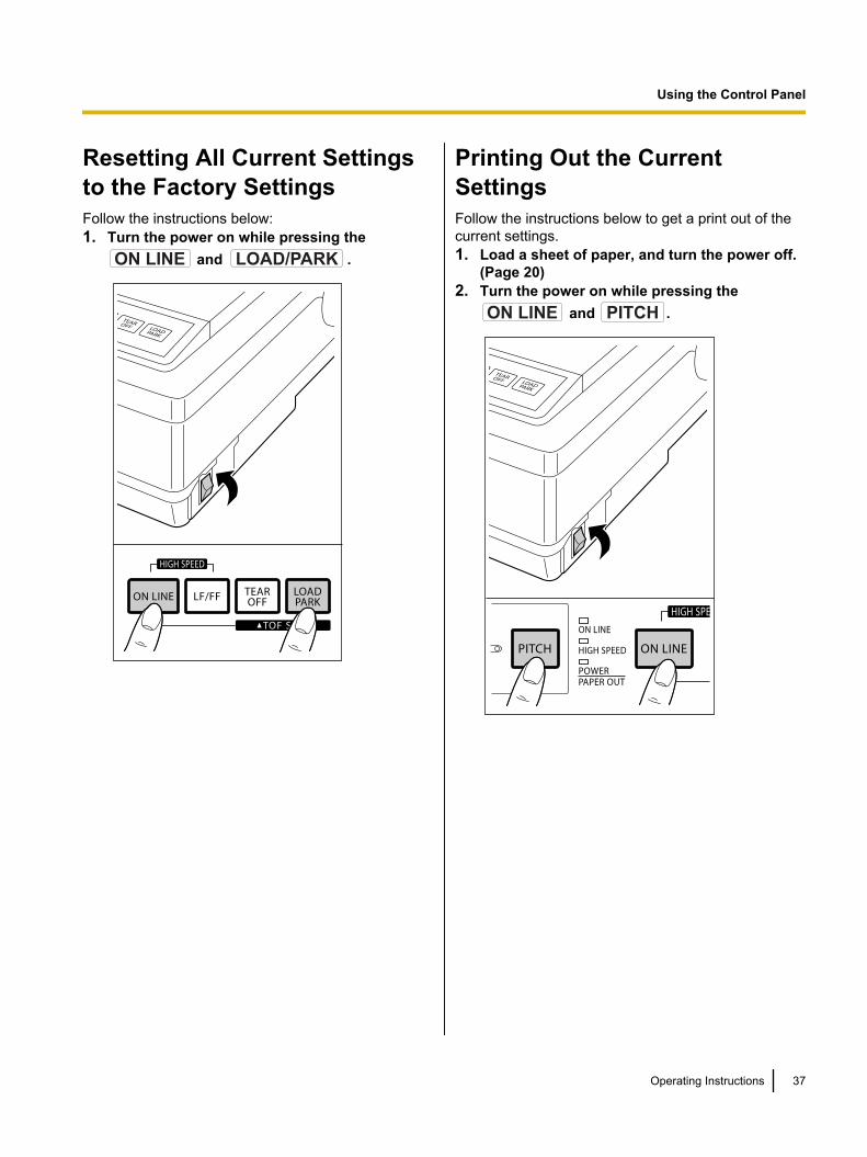
Resetting All Current Settingsto the Factory SettingsFollow the instructions below:1. Turn the power on while pressing the
ON LINE and LOAD/PARK .
Printing Out the CurrentSettingsFollow the instructions below to get a print out of thecurrent settings.1. Load a sheet of paper, and turn the power off.
(Page 20)2. Turn the power on while pressing the
ON LINE and PITCH .
Operating Instructions 37
Using the Control Panel

Periodic MaintenanceThe printer does not require any routine maintenance. However, reasonable care of the printer will extend itslife. The following periodic measures are recommended:
• Cleaning the unit is the most important action the user can perform.The frequency of cleaning is dependent upon the environment.– Turn the power off and unplug the AC power cord.– Clean the case and covers with a soft cloth. Use any mild commercial cleaner on the cloth, do not spray
directly on the printer.– Raise the top cover and pull up the roller cover. Vacuum or dust the inside area of the unit. Be very
careful not to damage the printhead ribbon cable or the carriage drive belt.
CAUTION• The printhead may be hot, use caution when the cover is open.
– The platen should be cleaned with denatured alcohol only.– The carriage guide bar can be lubricated with a very light oil. Contact your Authorized Panasonic
Service Center for advice on lubrication.
Ribbon CassetteNote
• If the ribbon cassette begins to catch, snag, or tear from the printhead, your printer requires servicing.
38 Operating Instructions
M
a
i
n
t
e
n
a
n
c
e
&
T
r
o
u
b
l
e
s
h
o
o
t
i
n
g
Maintenance & Troubleshooting
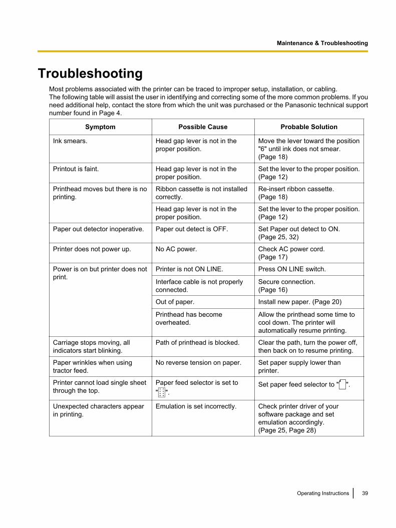
TroubleshootingMost problems associated with the printer can be traced to improper setup, installation, or cabling.The following table will assist the user in identifying and correcting some of the more common problems. If youneed additional help, contact the store from which the unit was purchased or the Panasonic technical supportnumber found in Page 4.
Symptom Possible Cause Probable Solution
Ink smears. Head gap lever is not in theproper position.
Move the lever toward the position"6" until ink does not smear.(Page 18)
Printout is faint. Head gap lever is not in theproper position.
Set the lever to the proper position.(Page 12)
Printhead moves but there is noprinting.
Ribbon cassette is not installedcorrectly.
Re-insert ribbon cassette.(Page 18)
Head gap lever is not in theproper position.
Set the lever to the proper position.(Page 12)
Paper out detector inoperative. Paper out detect is OFF. Set Paper out detect to ON.(Page 25, 32)
Printer does not power up. No AC power. Check AC power cord.(Page 17)
Power is on but printer does notprint.
Printer is not ON LINE. Press ON LINE switch.
Interface cable is not properlyconnected.
Secure connection.(Page 16)
Out of paper. Install new paper. (Page 20)
Printhead has becomeoverheated.
Allow the printhead some time tocool down. The printer willautomatically resume printing.
Carriage stops moving, allindicators start blinking.
Path of printhead is blocked. Clear the path, turn the power off,then back on to resume printing.
Paper wrinkles when usingtractor feed.
No reverse tension on paper. Set paper supply lower thanprinter.
Printer cannot load single sheetthrough the top.
Paper feed selector is set to" ".
Set paper feed selector to " ".
Unexpected characters appearin printing.
Emulation is set incorrectly. Check printer driver of yoursoftware package and setemulation accordingly.(Page 25, Page 28)
Operating Instructions 39
Maintenance & Troubleshooting
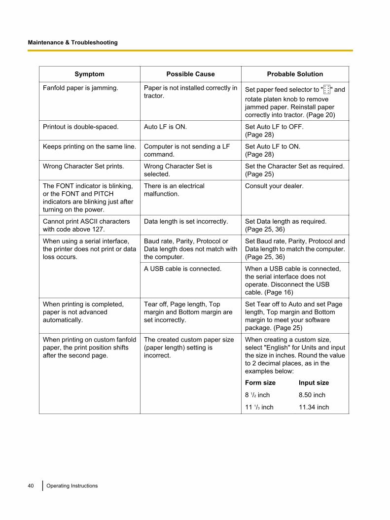
Symptom Possible Cause Probable Solution
Fanfold paper is jamming. Paper is not installed correctly intractor.
Set paper feed selector to " " androtate platen knob to removejammed paper. Reinstall papercorrectly into tractor. (Page 20)
Printout is double-spaced. Auto LF is ON. Set Auto LF to OFF.(Page 28)
Keeps printing on the same line. Computer is not sending a LFcommand.
Set Auto LF to ON.(Page 28)
Wrong Character Set prints. Wrong Character Set isselected.
Set the Character Set as required.(Page 25)
The FONT indicator is blinking,or the FONT and PITCHindicators are blinking just afterturning on the power.
There is an electricalmalfunction.
Consult your dealer.
Cannot print ASCII characterswith code above 127.
Data length is set incorrectly. Set Data length as required.(Page 25, 36)
When using a serial interface,the printer does not print or dataloss occurs.
Baud rate, Parity, Protocol orData length does not match withthe computer.
Set Baud rate, Parity, Protocol andData length to match the computer.(Page 25, 36)
A USB cable is connected. When a USB cable is connected,the serial interface does notoperate. Disconnect the USBcable. (Page 16)
When printing is completed,paper is not advancedautomatically.
Tear off, Page length, Topmargin and Bottom margin areset incorrectly.
Set Tear off to Auto and set Pagelength, Top margin and Bottommargin to meet your softwarepackage. (Page 25)
When printing on custom fanfoldpaper, the print position shiftsafter the second page.
The created custom paper size(paper length) setting isincorrect.
When creating a custom size,select "English" for Units and inputthe size in inches. Round the valueto 2 decimal places, as in theexamples below:
Form size Input size
8 1/2 inch 8.50 inch
11 1/3 inch 11.34 inch
40 Operating Instructions
Maintenance & Troubleshooting
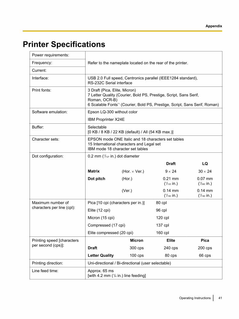
Printer SpecificationsPower requirements:
Refer to the nameplate located on the rear of the printer.Frequency:
Current:
Interface: USB 2.0 Full speed, Centronics parallel (IEEE1284 standard),RS-232C Serial interface
Print fonts: 3 Draft (Pica, Elite, Micron)7 Letter Quality (Courier, Bold PS, Prestige, Script, Sans Serif, Roman, OCR-B)6 Scalable Fonts*1 (Courier, Bold PS, Prestige, Script, Sans Serif, Roman)
Software emulation: Epson LQ-300 without color
IBM Proprinter X24E
Buffer: Selectable[0 KB / 8 KB / 22 KB (default) / All (54 KB max.)]
Character sets: EPSON mode ONE Italic and 18 characters set tables15 International characters and Legal setIBM mode 18 character set tables
Dot configuration: 0.2 mm (1/127 in.) dot diameter
Draft LQ
Matrix (Hor. ´ Ver.) 9 ´ 24 30 ´ 24
Dot pitch (Hor.) 0.21 mm(1/120 in.)
0.07 mm(1/360 in.)
(Ver.) 0.14 mm(1/180 in.)
0.14 mm(1/180 in.)
Maximum number of characters per line (cpl):
Pica [10 cpi (characters per in.)] 80 cpl
Elite (12 cpi) 96 cpl
Micron (15 cpi) 120 cpl
Compressed (17 cpi) 137 cpl
Elite compressed (20 cpi) 160 cpl
Printing speed [charactersper second (cps)]:
Micron Elite Pica
Draft 300 cps 240 cps 200 cps
Letter Quality 100 cps 80 cps 66 cps
Printing direction: Uni-directional / Bi-directional (user selectable)
Line feed time: Approx. 65 ms[with 4.2 mm (1/6 in.) line feeding]
Operating Instructions 41
A
p
p
e
n
d
i
x
Appendix
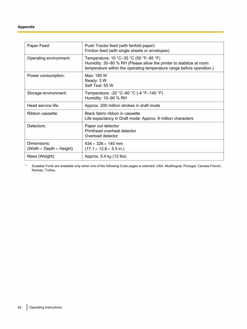
Paper Feed: Push Tractor feed (with fanfold paper)Friction feed (with single sheets or envelopes)
Operating environment: Temperature: 10 °C–35 °C (50 °F–95 °F)Humidity: 30–80 % RH (Please allow the printer to stabilize at roomtemperature within the operating temperature range before operation.)
Power consumption: Max: 180 WReady: 3 WSelf Test: 55 W
Storage environment: Temperature: -20 °C–60 °C (-4 °F–140 °F)Humidity: 10–90 % RH
Head service life: Approx. 200 million strokes in draft mode
Ribbon cassette: Black fabric ribbon in cassetteLife expectancy in Draft mode: Approx. 6 million characters
Detectors: Paper out detectorPrinthead overheat detectorOverload detector
Dimensions:(Width ´ Depth ´ Height)
434 ´ 326 ´ 140 mm(17.1 ´ 12.8 ´ 5.5 in.)
Mass (Weight): Approx. 5.4 kg (12 lbs)
*1 Scalable Fonts are available only when one of the following Code pages is selected: USA, Multilingual, Portugal, Canada French,Norway, Turkey.
42 Operating Instructions
Appendix
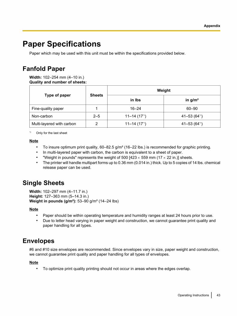
Paper SpecificationsPaper which may be used with this unit must be within the specifications provided below.
Fanfold PaperWidth: 102–254 mm (4–10 in.)Quality and number of sheets:
Type of paper SheetsWeight
in lbs in g/m²
Fine-quality paper 1 16–24 60–90
Non-carbon 2–5 11–14 (17*1) 41–53 (64*1)
Multi-layered with carbon 2 11–14 (17*1) 41–53 (64*1)
*1 Only for the last sheet
Note• To insure optimum print quality, 60–82.5 g/m² (16–22 lbs.) is recommended for graphic printing.• In multi-layered paper with carbon, the carbon is equivalent to a sheet of paper.• "Weight in pounds" represents the weight of 500 [423 ´ 559 mm (17 ´ 22 in.)] sheets.• The printer will handle multipart forms up to 0.36 mm (0.014 in.) thick. Up to 5 copies of 14 lbs. chemical
release paper can be used.
Single SheetsWidth: 102–297 mm (4–11.7 in.)Height: 127–363 mm (5–14.3 in.)Weight in pounds (g/m²): 53–90 g/m² (14–24 lbs)
Note• Paper should be within operating temperature and humidity ranges at least 24 hours prior to use.• Due to letter head varying in paper weight and construction, we cannot guarantee print quality and
paper handling for all types.
Envelopes#6 and #10 size envelopes are recommended. Since envelopes vary in size, paper weight and construction,we cannot guarantee print quality and paper handling for all types of envelopes.
Note• To optimize print quality printing should not occur in areas where the edges overlap.
Operating Instructions 43
Appendix
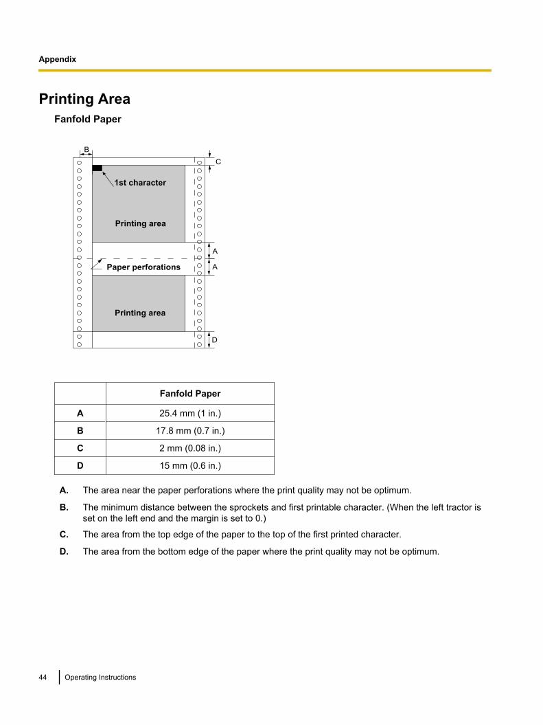
Printing AreaFanfold Paper
1st character
Paper perforations
Printing area
Printing area
A
D
B
A
C
Fanfold Paper
A 25.4 mm (1 in.)
B 17.8 mm (0.7 in.)
C 2 mm (0.08 in.)
D 15 mm (0.6 in.)
A. The area near the paper perforations where the print quality may not be optimum.
B. The minimum distance between the sprockets and first printable character. (When the left tractor isset on the left end and the margin is set to 0.)
C. The area from the top edge of the paper to the top of the first printed character.
D. The area from the bottom edge of the paper where the print quality may not be optimum.
44 Operating Instructions
Appendix
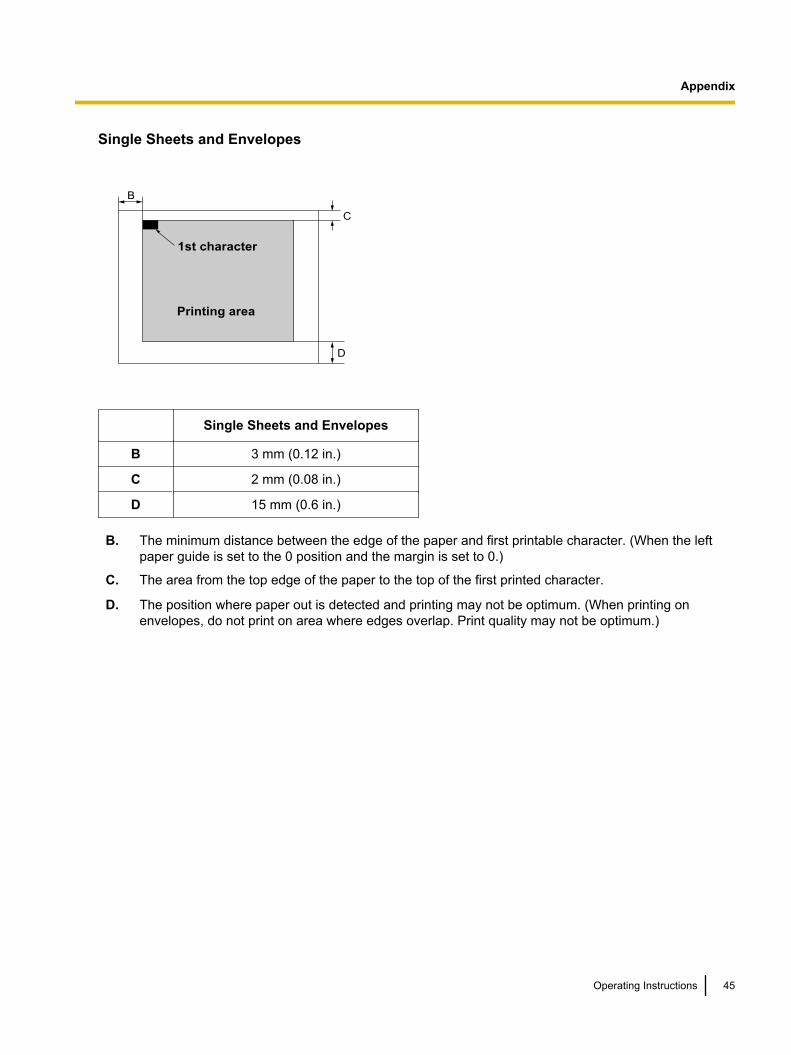
Single Sheets and Envelopes
B
D
C
1st character
Printing area
Single Sheets and Envelopes
B 3 mm (0.12 in.)
C 2 mm (0.08 in.)
D 15 mm (0.6 in.)
B. The minimum distance between the edge of the paper and first printable character. (When the leftpaper guide is set to the 0 position and the margin is set to 0.)
C. The area from the top edge of the paper to the top of the first printed character.
D. The position where paper out is detected and printing may not be optimum. (When printing onenvelopes, do not print on area where edges overlap. Print quality may not be optimum.)
Operating Instructions 45
Appendix
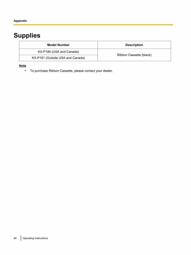
SuppliesModel Number Description
KX-P180 (USA and Canada)Ribbon Cassette (black)
KX-P181 (Outside USA and Canada)
Note• To purchase Ribbon Cassette, please contact your dealer.
46 Operating Instructions
Appendix
IndexAAlternate Graphic Mode (A.G.M.) 26, 35Auto CR 26, 35Auto LF 26, 34, 40Auto load 26, 35Auto Online 26, 35
BBi direction 26Bold PS 41Buffer 26, 35, 41
CCAUTION 7CD-ROM 11Character Per Line 41Character set 26, 35, 41Code page 26, 35Connecting 16Control Panel 14, 28, 34Control Panel Software Program 25Courier 41
DData length 26, 36Detectors 32, 42
Overheat detector 42Overload detector 42Paper Out detector 42
Dot configuration 41Dot matrix 41
EElite 41Emulation 25, 34
Epson LQ-850 25IBM Proprinter X24E 25
Extension Plate 11
FFactory Settings 33, 36, 37Fanfold paper 12, 20, 42FONT indicators 14, 34FONT switch 14Form Feed (FF) 29Friction 12, 22
GGraphic direction 26, 34
HHead gap lever 12Head service life 42HIGH SPEED indicator 14High Speed mode 29
IInitial Setup mode 33Interface 26, 41Italic 26
LLF/FF switch 14Line Feed (LF) 29LOAD/PARK switch 14
MMaintenance 38Margin 25Micro line feed 30Micron 41
OON LINE indicator 14, 34ON LINE switch 14Operating environment 10Overheat detector 42Overload detector 42
PPage format 25Page length 25, 34Paper 43
installation 20, 22specifications 43
Paper Feed 42Friction Mode 22, 42Tractor Mode 20, 42
Paper feed selector 12Paper out detector 42Paper support 12Paper thickness 12Parallel interface cable 16Parallel interface connector 12, 16Parts of the Printer 12Pica 41Pitch 25, 28, 34, 41PITCH indicators 14, 34PITCH switch 14, 28Platen knob 11, 13Power cord 13Power requirements 41Power switch 13POWER/PAPER OUT indicator 14
Operating Instructions 47
Index
Precautions 10Prestige 41Print Font 41Printer driver 16Printing Area 44Printing direction 41Printing Speed 2, 41Proportional Spacing (P.S) 34
RReverse micro line feed 30Ribbon cassette 11, 18, 38
SSelf Test 24Serial interface 26Serial interface cable 16Serial interface connector 12, 16Serial Interface Setup mode 36Single sheet 22, 43, 45Smoked plastic cover 12Specifications 41, 43
TTear off 26, 29, 34TEAR OFF switch 14Text direction 26TOF Setting 26Top cover 12Top of Form (TOF) set 30Tractor clamping levers 20Tractors 13Troubleshooting 39
UUni direction 26Unpacking 11USB cable 16USB connector 12, 16
WWARNING 7
ZZero font 26, 35
48 Operating Instructions
Index

PJQXC0334ZA KK0210KU0© Panasonic System Networks Co., Ltd. 2010
Web Site: http://www.panasonic.net/