kxc - motorgear
TRANSCRIPT

100
5.6 Abmessungen5.6 Dimensions5.6
KXC
XXA
XXF
XXC
q
Vstupní hřídel
Výstupní dutá hřídel

101
5.6 Abmessungen5.6 Dimensions5.6
Side cover for shaft mounting
KXC - XXC - XXF -XXAa A b be b2 B C1 C2 D2 Et Eq E2 f2 G h8 h h1 h2 H H1 H2
30/30 54 80 44
3
5 — 56
31.5
31.5
9
14 —
41 40
40 6.5 55 71 27 44 97 40 5730/40 70 105 60 6 6 71 39 18 19 50 6.5 60 90 35 55 125 50 7530/50 80 125 70
88 85 46
2524 60 8.5 70 104 40 64 150 60 90
30/63100 147 85 — 103 56 — 72 9 80 130 50 80 182 72 110
40/634 39 11 51 50
40/75120 176 90 8 8 112 60 28 30 86 11 95 153 60 93 219.5 86 133.5
50/75 5 46 14 60 6040/90
140 203 1004
10 — 13039
7011
35 —51 50
103 13 110 172 70 102 248.5 103 145.550/90
5 46 14 60 6050/110
170 252.5 115 12 — 143 77.5 42 — 127.5 14 130 210 85 125 310.5 127.5 18363/110 6 56 19 71 7263/130 200 292.5 120 6 14 14 155 56 85 19 45 48 — 72 147.5 15 180 240 100 140 355 147.5 207.5
KXC - XXC - XXF -XXAI I1 I2 Jt Jq Kc Kq L Lt M Me N PP R S Tt Tq te t2 X
30/30 100
31.5
31.5
37.5 40 57 57 15
171.5
44.5
29 65 5.5
52.5 57 10.2
16.3 — 1.530/40 122 40 203.5 36.5 75 6 20.8 21.8 1.530/50 132 50 223.5 43.5 85 7
28.327.3 1.5
30/63 14563
248.553 95 8 — 2
40/63 15040 43.5 50 75 75 20
26157.5 68.5 75 12.5
40/75 174.575
299.557 115 10 31.3 33.3 2
50/75 190 50 53.5 60 82 82 25 322 67.5 82.5 90 1640/90 184.5 40
9043.5 50 75 75 20 326.5 57.5
67 130 1268.5 75 12.2
38.3 — 250/90 200
50 53.5 60 82 82 25349
67.5 82.5 90 1650/110 226
110399.5
74 165 14 45.3 — 2.563/110 236 63 64 72 97 95 30 419.5 77.5 100.5 110 21.563/130 256 63 130 — 72 97 95 30 459.5 77.5 81 215 15 — 110 21.5 48.8 51.8 3
30/40 - 30/5030/30 30/63 - 40/63 - 40/75 - 40/90 - 50/7550/90 - 50/110 - 63/110 - 63/130
4 díry4 díry 8 děr
102
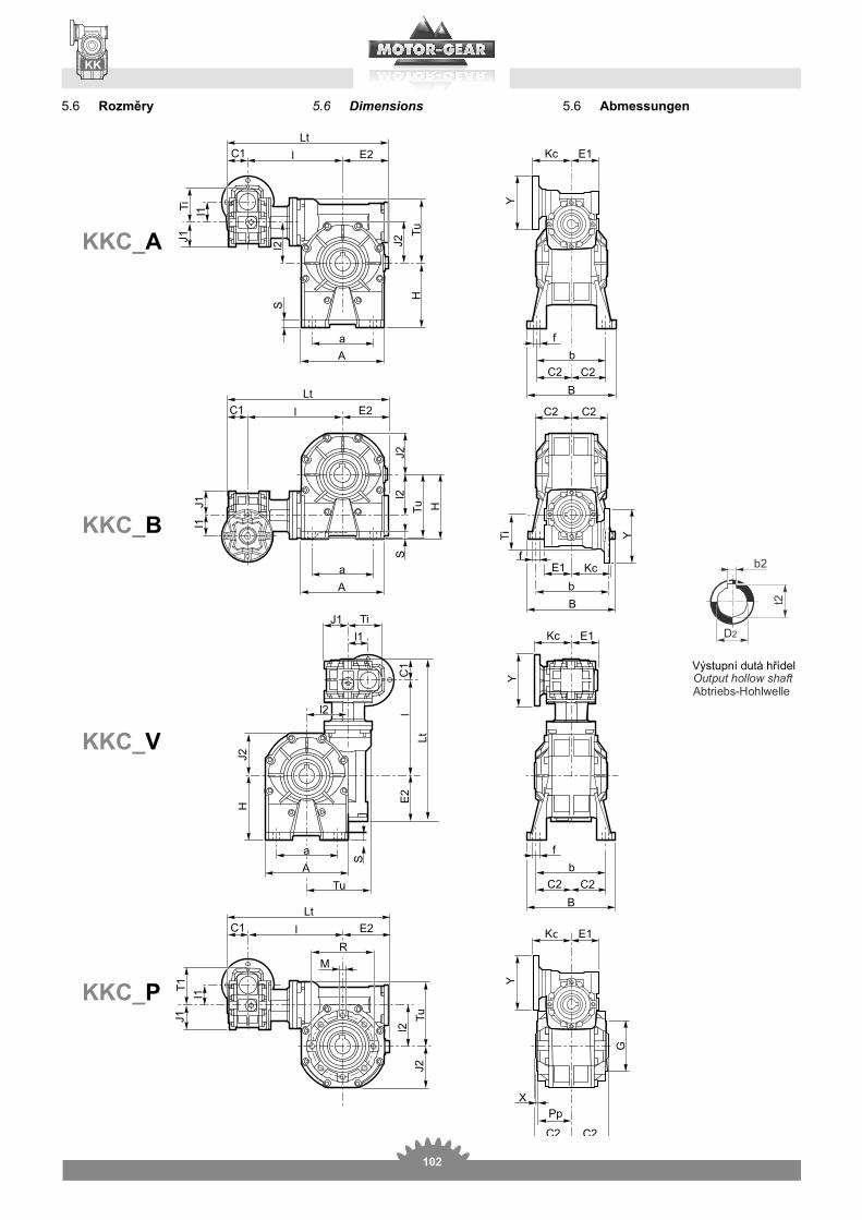
5.6 Abmessungen5.6 Dimensions5.6
KKC_A
KKC_B
KKC_V
KKC_P
c
Výstupní dutá hřídel

103
5.6 Abmessungen5.6 Dimensions5.6
KKCA a B b f H S
b2 C1 C2 D2 E1 E2 G h81 2 1 2 1 2 1 2 1 2 1 2 1 2
30/30 67 40-52 78 66 6.5 52 55 5 8 5 —
31.5
31.5 14 —
41
41 5530/40 86.5 70 52 98 84 81 7 8.5 71 72 9 10 6 6 39 18 19 51 6030/50 106 63-85 119 99 9 85 82 11 8
88 46
2524 60 70
30/63127.5 95 136 111 11 100 12 — 56 — 71 80
40/6339 51
40/75155.5 120 140 115 11 115 12 8 — 60 28 30 85 95
50/75 46 6040/90
190 140 168 140 146 13 11 135 142 14 10 —39
70 35 —51
103 11050/90
46 6050/110
250 200 210 162 181 13 13 171 170 17 15 12 — 77.5 42 — 127.5 13063/110 56 7163/130 295 235 220 229 190 191 15 200 195 20 15 14 56 85 45 48 71 147.5 180
KKCI I1 I2 J1 J2 Kc Lt M PP R Ti Tu t2 X
30/30 100
31.5
31.5
37.5
37.5
57
171.5 29 65
52.5
Tu 16.3 — 1.530/40 122 40 43.5 203.5 36.5 75 52.5 20.8 21.8 1.530/50 132 50 53.5 223.5 43.5 85 68.5
28.327.3 1.5
30/63 14763 64
248.553 95
82.5— 2
40/63 15240 43.5 75
26168.5 100.5
40/75 176.575 78
301.557 115 31.3 — 2
50/75 192 50 53.5 82 324 82.5116.5
40/90 186.5 4090
43.5100
75 328.567 130
68.538.3 — 2
50/90 20250 53.5 82
35182.5 131.5
50/110 226110 122
399.574 165 45.3 — 2.5
63/110 236 63 64 97 419.5 100.5 161.563/130 256 63 130 64 131 97 459.5 81 215 100.5 181 48.8 51.8 3
Side cover for shaft mounting
30/40 - 30/5030/30 30/63 - 40/63 - 40/75 - 40/90 - 50/75 50/90 - 50/110 - 63/110 - 60/130
4 díry4 díry 8 děr
104
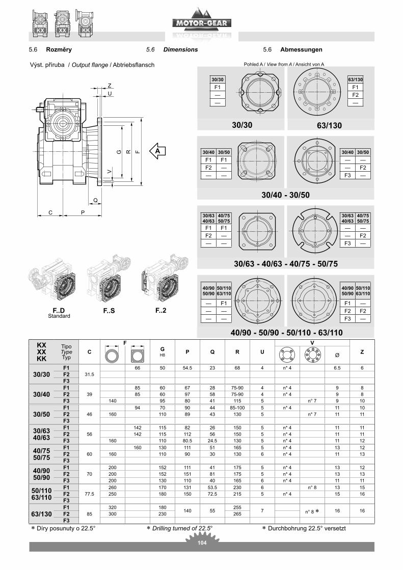
Output flange
KXXXKK
TipoType C
FG P Q R U
VZØ
30/30F1
31.566 50 54.5 23 68 4 6.5 6
F2F3
30/40F1
3985 60 67 28 75-90 4 9 8
F2 85 60 97 58 75-90 4 9 8F3 140 95 80 41 115 5 9 10
30/50F1
4694 70 90 44 85-100 5 11 10
F2 160 110 89 43 130 5 11 11F3
30/6340/63
F156
142 115 82 26 150 5 11 11F2 142 115 112 56 150 5 11 11F3 160 110 80.5 24.5 130 5 11 12
40/7550/75
F160
160 130 111 51 165 5 13 12F2 160 110 90 30 130 6 11 13F3
40/9050/90
F170
200 152 111 41 175 5 13 12F2 200 152 151 81 175 5 13 13F3 200 130 110 40 165 6 11 11
50/11063/110
F177.5
260 170 131 53.5 230 6 13 15F2 250 180 150 72.5 215 5 15 16F3
63/130F1
85320 180
140 55255
7 16 16F2 300 230 265F3
30/30
——
30/40 30/50— ——
—
30/40 30/50
—— —
30/6340/63
40/7550/75
— ——
—
30/6340/63
40/7550/75
—— —
40/9050/90
50/11063/110
—
—
40/9050/90
50/11063/110
—— —— —
View from A
5.6 Abmessungen5.6 Dimensions5.6
63/130
—
Drilling turned of 22.5°
Výst. příruba

105
N.B.: it is possible to create hybrid combina-tions with the existing flanges.
Input flange
KXCXXCKKC
IEC G1
PM
R1 U1
V1
Z1
Holes diameter IEC
1 2 Ø150200300
450 600 900 1200 15002500
19503250 4000 5000
10000
30/3030/4030/5030/63
80 100 4 7 8 120 8 9 9 9 9 9 9 9 9 950 65 3.5 6 8 80 8 9 9 9 9 9 9 9 9 995 115 4 9 8 140 8 11 11 11 11 11 1160 75 4 6 8 90 8 11 11 11 11 11 11
40/6340/7540/90
80 100 4 7 8 120 9 9 9 9 950 65 3.5 6 4 80 8 9 9 9 995 115 4 9 8 140 9 11 11 11 11 11 11 11 11 1160 75 3.5 6 4 90 8 11 11 11 11 11 11 11 11 11110 130 4.5 9 8 160 10 14 14 14 14 1470 85 3.5 7 8 105 8 14 14 14 14 14
50/7550/9050/110
95 115 4 9 8 140 9 11 11 11 11 1160 75 3.5 6 4 90 8 11 11 11 11 11110 130 4.5 9 8 160 10 14 14 14 14 14 14 14 14 1470 85 3.5 7 4 105 8 14 14 14 14 14 14 14 14 14
130 165 4.5 11 8 200 10 19 19 19 19 1980 100 4 7 8 120 10 19 19 19 19 19
63/11063/130
110 130 4.5 9 8 160 10 14 14 14 14 1470 85 3.5 7 4 105 10 14 14 14 14 14
130 165 4.5 11 8 200 10 19 19 19 19 19 19 19 19 1980 100 4 7 4 120 10 19 19 19 19 19 19 19 19 19
130 165 4.5 11 8 200 10 24 24 24 2495 115 4 8.5 8 140 10 24 24 24 24
5.6 Abmessungen5.6 Dimensions5.6
Vst. příruba

106
Drehmomentbegrenzer5.7 Torque limiter with through hollow shaft
-onen (Getriebe am Abtrieb).
The values listed in the table refer to torque limiters in the LS and LD ver-sions (output gearbox).
XX-KXKK
N°. revolutions of ring nut 1 2 3 4
30/30 22 27 33 38 4330/40 55 64 73 8730/50 75 97 120 15730/63
127 155 180 205 232 260 28240/6340/75
235 265 295 327 360 407 45550/7540/90
320 349 400 440 475 517 550 595 630 650 67050/9050/110
720 815 910 1000 1100 125063/11063/130
5.6 Abmessungen5.6 Dimensions5.6
XXF IEC
PMG1 KF
V1
Z11 2 R1 U1 Ø
30/3030/4030/5030/63
80 82.5 100 3.5 7 8 120 850 82.5 65 3.5 6 4 80 895 85.5 115 4 9 8 140 1060 85.5 75 3.5 6 8 90 8
40/6340/7540/90
80 101.5 100 3.5 7 8 120 895 104.5 115 4 9 140 1060 104.5 75 3.5 6 8 90 8110 111.5 130 4.5 9 8 160 1070 111.5 85 4 7 8 105 10
50/7550/9050/110
95 119.5 115 4 9 8 140 10110 126.5 130 4.5 9 8 160 1070 126.5 85 3.5 7 105 10
130 136.5 165 4.5 11 8 200 1080 136.5 100 4 7 8 120 10
63/11063/130
110 141.5 130 4.5 9 8 160 10130 161.5 165 4.5 11 8 200 1080 151.5 100 4 7 8 120 1095 161.5 115 4 9 8 140 10
Input flangeVst. příruba

107
SERIES (min. torque, max sensitivity)SERIE
Washers’ arrangement
XX - KXC2 CL Ct
D2 M2 G2LD - LS30/30 31.5 55.5 87 1430/40 39 65 10430/50 46 76 12230/63
56 91 147 2540/6340/75
60 100 16050/7540/90
70 109 17950/9050/110
77.5 127.5 205 4263/11063/130
Drehmomentbegrenzer5.7 Torque limiter with through hollow shaft
LD LS L1*XX - KX
C1L130/3030/4030/5030/63
55.5
40/6340/7540/90
65
50/7550/90 76
63/110 91
63/130 91
* L1 torque limiter in combined gearboxes
--
-
-
-
-
--
--
-
-
-
The version with torque limiter mounted on the gearbox at input (L1), although made of standard component, is to be regarded as a special execution from the utilization point of view.Actually, the L1 limiter calibration value, even though set to its minimum, gener-ates on the second gearbox a very high torque which often exceeds the maximum admissible value.As a consequence, calibration is not pre-cise: any variation of the torque on the first gearbox is to be multiplied by the ra-tio of the gearbox at output.The choice of the limiter at input (L1) cannot be based on the fact that the price of the limiter at input is lower than that at output.Nevertheless, this is a good solution if the application requires at the same time both the limitation of the power transmitted by the motor and the irreversibility on the second gearbox without any risk of slidingFor the above mentioned reasons, the torque limiter at input (L1) is supplied in free position, i.e. the customer will carry out the limiter calibration according to the customer’s requirements.
-
-
-
-

108
Versionen mit Doppelseitigle
5.8 Double extended worm shaft design
Druhý vstup
SeA2
KXC - XXCXXF - XXA
KKC
SeA1 SeA2
b l mn
t B D L MN
TKX XX KX XX
30/30 3 9 15 42.5 42.5 10.2 3 9 15 42.5 42.5 10.230/40 3 9 15 42.5 42.5 10.2 4 11 20 52.5 52.5 12.530/50 3 9 15 42.5 42.5 10.2 5 14 25 62.5 62.5 1630/63 3 9 15 42.5 42.5 10.2 6 19 30 72.5 74.5 21.540/63 4 11 20 52.5 52.5 12.5 6 19 30 72.5 74.5 21.540/75 4 11 20 52.5 52.5 12.5 8 24 40 93 91 2750/75 5 14 25 62.5 62.5 16 8 24 40 93 91 2740/90 4 11 20 52.5 52.5 12.5 8 24 40 108 108 2750/90 5 14 25 62.5 62.5 16 8 24 40 108 108 2750/110 5 14 25 62.5 62.5 16 8 28 50 132 132 3163/110 6 19 30 72.5 74.5 21.5 8 28 50 132 132 3163/130 6 19 30 72.5 74.5 21.5 10 38 70 152 152 41
SeA1
--
-
The second input shaft of the output gear-box (SeA2) can not be utilized as a drive because its motion will be stopped by the reversibility of the first gearbox. If utilized as a drive shaft its speed will be equal to the input speed decreased by the ratio of the first gearbox.
-

109
5.9 Accessories5.9 Accessories
Output shaft
Single output shaft Double output shaft
KK-KX-XX A Ab B Bb h6 1 e L Lb M m S Sb
30/30 30 29 62 64 14 18.5 20 94.5 126 M6 16 2.5 2.530/40 40 39 77 79 18 23.5 30 120 161 M6 16 3 330/50 50 49 90 93 25 31.5 40 143.5 195 M8 22 3.5 3.530/6340/63 50 49 111 113 25 31.5 40 165 216 M8 22 4 440/7550/75 60 59 119 121 28 34.5 50 183 244 M8 22 4 440/9050/90 80 78.5 139 141.5 35 41.5 60 224 305 M10 28 5 550/11063/110 80 77.5 154.5 157 42 49.5 60 242.5 322.5 M10 28 8 8
63/130 80 78 168 172 45 54.5 70 253 335 M16 36 5 5
Torque arm Drehmomentstütze
pouze u verze P Protection Kit: Schutzvorrichtung:
Available options:
Tapered roller bearing on wormgearerhältlich:
Hollow shaft Torque limiter
KKKXXX
a b D1 E H K Lt O S1 S2
30/30 85 37.5 55 65 8 24 141.5 7 14 430/40 100 45 60 75 10 31.5 167 7 14 430/50 100 50 70 85 10 39 172 9 14 530/6340/63 150 55 80 95 10 49 227 9 14 640/7550/75 200 70 95 115 20 47.5 302 9 25 640/9050/90 200 80 110 130 20 57.5 312 11 25 650/11063/110 250 100 130 165 25 62 390 11 30 6
63/130 250 125 180 215 25 69 415 13 30 6
KKKXXX
A B C
30/30
12
12
13
13
39
3930/40 14 15.5 4430/50 15 16.5 5430/63 17 19 6040/63 14 15.5 4440/75 18 20 7050/75 15 16.5 5440/90 14 21.5 15.5 24 44 8050/90 15 16.5 5450/110 22 25 9663/110 17 19 60
63/130 17 22 19 25 60 130
KKKXXX
A B C
30/30
36
36
37
37
36
3630/40 40 41.5 4430/50 47 48.5 5330/63 52 54 5540/63 40 41.5 4440/75 58 60 6850/75 47 48.5 5340/90 40 60.5 41.5 63 44 7050/90 47 48.5 5350/110 72 75 8563/110 52 54 55
63/130 52 54 55