kveb electrical displacement series 90 pumps controlfiles.danfoss.com/documents/kveb electrical...
TRANSCRIPT
MAKING MODERN LIVING POSSIBLE
Technical Information
Series 90 PumpsKVEB Electrical DisplacementControl
powersolutions.danfoss.com

Revision history Table of revisions
Date Changed Rev
April 2015 Danfoss layout CA
June 2013 major revision BA
November 2003 First edition -
Technical Information KVEB Electrical Displacement Control for Series 90 Pumps
2 BLN-95-9060 • Rev CA • April 2015

General InformationKVEB.......................................................................................................................................................................................................4Features and Benefits......................................................................................................................................................................4
SpecificationsTechnical Specifications.................................................................................................................................................................5Fluid selection....................................................................................................................................................................................6Filtration system .............................................................................................................................................................................. 6Performance Specifications.......................................................................................................................................................... 7Environmental Specifications...................................................................................................................................................... 7
Electrical CharacteristicsA Configuration.................................................................................................................................................................................9B and E Configuration..................................................................................................................................................................... 9
Design ParametersApplication....................................................................................................................................................................................... 10Current vs Swashplate Angle of the Single Coil KVEA (B&E configuration)..............................................................11Precautions when driving dual coil PCPs with a PWM driver........................................................................................ 12
OperationTheory of Operation......................................................................................................................................................................13Schematic Diagram....................................................................................................................................................................... 14
Model CodeKVEB - EDC........................................................................................................................................................................................ 15
OptionsIntrinsically Safe Control..............................................................................................................................................................16Wiring Options................................................................................................................................................................................16
Assembling the Female Tower Connector...................................................................................................................... 16
Mounting the ControlMounting Procedure.....................................................................................................................................................................18
Installing the Control...............................................................................................................................................................18
Adjustment ProcedurePump Neutral Adjustment..........................................................................................................................................................19
TroubleshootingPump Fails to Stroke Properly................................................................................................................................................... 21
Installation Drawings75cc, 100cc, 130cc, 180cc and 250cc pumps - EDC........................................................................................................... 2255cc pumps - EDC.......................................................................................................................................................................... 22
Technical Information KVEB Electrical Displacement Control for Series 90 Pumps
Contents
BLN-95-9060 • Rev CA • April 2015 3
KVEB
The KVEB Electrical Displacement Control (EDC) is a two-stage electrohydraulic pump stroke controlwhich uses mechanical feedback to establish closed loop control of the swashplate angle of DanfossSeries 90 Pumps.
The first stage, the MCV116 Pressure Control Pilot (PCP) is a torque-motor actuated, double-nozzleflapper valve that produces a differential output pressure proportional to the applied electrical signal.The second stage use the differential pressure to drive its unique spool arrangement and port oil to thepump servo cylinders. The second-stage spool configuration allows a null deadband (for machine safety)in the pump’s output while maintaining optimum dynamic response to control commands.
Features and Benefits
Features• Servo control deadband independent of signal null deadband: offers safety combined with accurate
and responsive control• Resistance to the environment: standard silicone oil filled torque motor, environmentally sealed first/
second stage interface, full environmental testing• Minimum long term null shift• Dual coil torque motor can be used to sum two command sources• Optional current (mA) ranges
Advantages of the KVE• Reduction in deceleration rollout characteristics• Optional input currents (part number specific)• Uses no loctite, which eases repair and internal parts
Technical Information KVEB Electrical Displacement Control for Series 90 Pumps
General Information
4 BLN-95-9060 • Rev CA • April 2015

Technical Specifications
Electrical
Full Stroke Current
A Configuration 18 ± 1.5 mA (single coil)
S Configuration 18 ± 2.0 mA (single coil)
B&E Configuration 14 ± 3.0 mA (single coil)
42 ± 5.6 mA (series coils)
85 ± 11.3 mA (parallel coils)
Refer to the Electrical Characteristics section for a complete range of currents.
Threshold Current
A Configuration 5 ± 1.0 mA
S Configuration 6 ± 1.5 mA
B&E Configuration 14 ± 3.0 mA
Nominal Input Impedance
A Configuration 650 Ohms for A/B coil
S Configuration 110 Ohms for A/B coil
B&E Configuration 20 Ohms for A/B coil
16 Ohms for C/D coil
Ratings
Scale Factor
A Configuration 6.2 psid/mA (single coil)
S Configuration 5.5 psid/mA (single coil)
B&E Configuration 1.15 psi/mA (single coil)
2.3 psi/mA (coils in series)
1.15 psi/mA (coils in parallel)
The EDC is designed to be controlled from a dc current source or a voltage source. Pulse widthmodulation (PWM) is not required. But, if a PWM signal is used use a carrier frequency ≥ 200 Hz. Do notuse a PWM current of more than 120% of that required for full output.
Technical Information KVEB Electrical Displacement Control for Series 90 Pumps
Specifications
BLN-95-9060 • Rev CA • April 2015 5
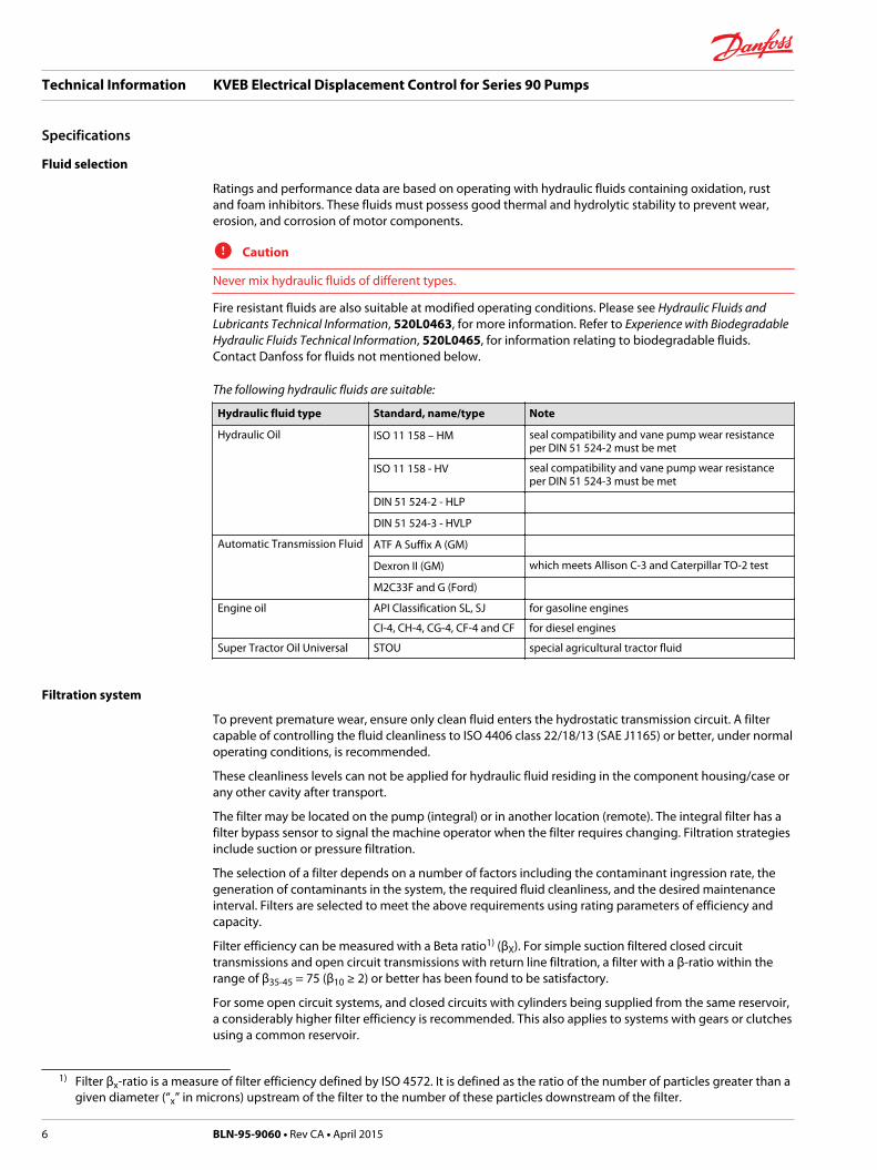
Fluid selection
Ratings and performance data are based on operating with hydraulic fluids containing oxidation, rustand foam inhibitors. These fluids must possess good thermal and hydrolytic stability to prevent wear,erosion, and corrosion of motor components.
C Caution
Never mix hydraulic fluids of different types.
Fire resistant fluids are also suitable at modified operating conditions. Please see Hydraulic Fluids andLubricants Technical Information, 520L0463, for more information. Refer to Experience with BiodegradableHydraulic Fluids Technical Information, 520L0465, for information relating to biodegradable fluids.Contact Danfoss for fluids not mentioned below.
The following hydraulic fluids are suitable:
Hydraulic fluid type Standard, name/type Note
Hydraulic Oil ISO 11 158 – HM seal compatibility and vane pump wear resistanceper DIN 51 524-2 must be met
ISO 11 158 - HV seal compatibility and vane pump wear resistanceper DIN 51 524-3 must be met
DIN 51 524-2 - HLP
DIN 51 524-3 - HVLP
Automatic Transmission Fluid ATF A Suffix A (GM)
Dexron II (GM) which meets Allison C-3 and Caterpillar TO-2 test
M2C33F and G (Ford)
Engine oil API Classification SL, SJ for gasoline engines
CI-4, CH-4, CG-4, CF-4 and CF for diesel engines
Super Tractor Oil Universal STOU special agricultural tractor fluid
Filtration system
To prevent premature wear, ensure only clean fluid enters the hydrostatic transmission circuit. A filtercapable of controlling the fluid cleanliness to ISO 4406 class 22/18/13 (SAE J1165) or better, under normaloperating conditions, is recommended.
These cleanliness levels can not be applied for hydraulic fluid residing in the component housing/case orany other cavity after transport.
The filter may be located on the pump (integral) or in another location (remote). The integral filter has afilter bypass sensor to signal the machine operator when the filter requires changing. Filtration strategiesinclude suction or pressure filtration.
The selection of a filter depends on a number of factors including the contaminant ingression rate, thegeneration of contaminants in the system, the required fluid cleanliness, and the desired maintenanceinterval. Filters are selected to meet the above requirements using rating parameters of efficiency andcapacity.
Filter efficiency can be measured with a Beta ratio1) (βX). For simple suction filtered closed circuittransmissions and open circuit transmissions with return line filtration, a filter with a β-ratio within therange of β35-45 = 75 (β10 ≥ 2) or better has been found to be satisfactory.
For some open circuit systems, and closed circuits with cylinders being supplied from the same reservoir,a considerably higher filter efficiency is recommended. This also applies to systems with gears or clutchesusing a common reservoir.
1) Filter βx-ratio is a measure of filter efficiency defined by ISO 4572. It is defined as the ratio of the number of particles greater than agiven diameter (“x” in microns) upstream of the filter to the number of these particles downstream of the filter.
Technical Information KVEB Electrical Displacement Control for Series 90 Pumps
Specifications
6 BLN-95-9060 • Rev CA • April 2015

For these systems, a charge pressure or return filtration system with a filter β-ratio in the range of β15-20 =75 (β10 ≥ 10) or better is typically required.
Because each system is unique, only a thorough testing and evaluation program can fully validate thefiltration system.
Please see Design Guidelines for Hydraulic Fluid Cleanliness Technical Information, 520L0467 for moreinformation.
Filtration, cleanliness level and βx-ratio (recommended minimum)
Cleanliness per ISO 4406 22/18/13
Efficiency βx (charge pressure filtration) β15-20 = 75 (β10 ≥ 10)
Efficiency βx (suction and return line filtration) β35-45 = 75 (β10 ≥ 2)
Recommended inlet screen mesh size 100 – 125 µm
Performance Specifications
Hysteresis - Less than 7 psi divided by the scale factor. Measured at a frequency of .01 Hz at 30% of ratedcurrent when run from plus to minus 98 psi divided by the scale factor.
Symmetry - The differences in the currents to drive to either side of rated output will not exceed 15%.
Linearity - No point plotted on the current/swashplate angle curve shall fall outside the area defined by a±10% slope deviation from the scale factor, exclusive of the deadband.
Fail Safety - The spool will return to neutral if the electrical signal is disconnected or if the pilot outputpressure goes to case pressure. Mechanical feedback must be present.
Frequency Response (except for 130 cc pumps)
2-3 Hz minimum with .052 pressure limiter orifices
3-4 Hz minimum without pressure limiter orifices (with pressure limiters inoperative)
Under 500-1000 psi load at 90° phase lag with 10 mA signal at 45 mA offset
Time Response (75 CC pumps)
B Configuration: 0 to full stroke 0.78 seconds (0.18 seconds without PL orifices)
Full to full stroke 1.40 seconds (0.30 seconds without PL orifices)
Full to 0 stroke 0.38 seconds (0.15 seconds without PL orifices)
E Configuration (All models are shipped without PL orifices)
0 to full stroke 0.13 seconds
Full to full stroke 0.24 seconds
Full to 0 stroke 0.13 seconds
Sensitivity - The valve will respond to a 2% change in input current throughout the rated current rangeexcept for the deadband region.
Environmental Specifications
Shock - 50 Gs for 11 milliseconds. Three shocks in both directions of the three mutually perpendicularaxes for a total of 18 shocks.
Vibration - Withstands a vibration test designed for mobile equipment control consisting of two parts:1. Cycling from 5 to 2000 Hz in each of the three axes.2. Resonance dwell for one million cycles for each resonance point in each of the three axes.
Technical Information KVEB Electrical Displacement Control for Series 90 Pumps
Specifications
BLN-95-9060 • Rev CA • April 2015 7

Subject to acceleration levels of 1 G to 46 Gs.
Acceleration level varies with frequency.
Humidity - After being placed in a controlled atmosphere of 95% humidity at 49° C (120° F) for 10 days,the EDC will perform within specification limits. Meets MIL-STD-810B.
Technical Information KVEB Electrical Displacement Control for Series 90 Pumps
Specifications
8 BLN-95-9060 • Rev CA • April 2015
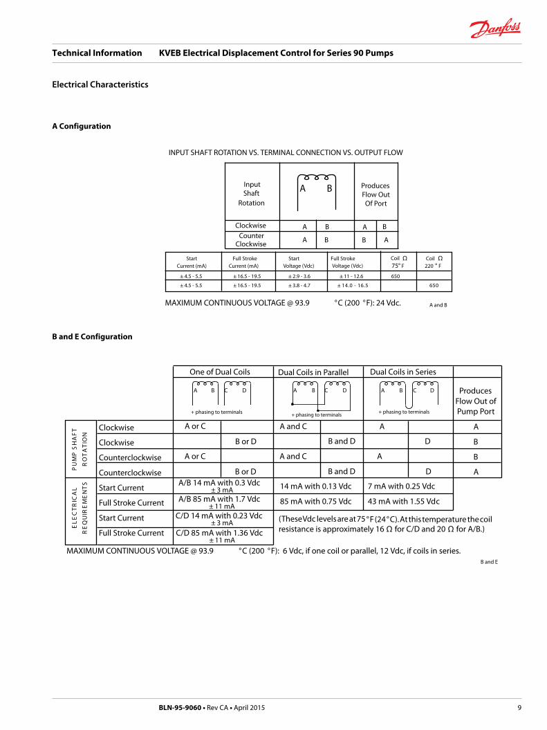
A Configuration
INPUT SHAFT ROTATION VS. TERMINAL CONNECTION VS. OUTPUT FLOW
InputShaft
Rotation
ProducesFlow OutOf Port
ClockwiseCounter A B
A B A
B
B
AClockwise
MAXIMUM CONTINUOUS VOLTAGE @ 93.9 °C (200 °F): 24 Vdc.
A B
Start Full Stroke Start Full Stroke Ω Coil ΩCurrent (mA) Current (mA) 75° F 220 ° F
± 4.5 - 5.5 ± 16.5 - 19.5 ± 2.9 - 3.6 ± 11 - 12.6 650
± 4.5 - 5.5 ± 16.5 - 19.5 ± 3.8 - 4.7 ± 0565.61 - 0.41
Coil Voltage (Vdc) Voltage (Vdc)
A and B
B and E Configuration
7 mA with 0.25 Vdc
43 mA with 1.55 Vdc
MAXIMUM CONTINUOUS VOLTAGE @ 93.9 °C (200 °F): 6 Vdc, if one coil or parallel, 12 Vdc, if coils in series.
Clockwise
Clockwise
Counterclockwise
Counterclockwise
Start Current
Full Stroke Current
Start Current
Full Stroke Current
TF
AH
S P
MU
P
NO I
TA
TO
R
LA
C IR
TC
EL
E
ST
NE
ME
R IU
QE
R
A or C
B or D
A and C A
D
One of Dual Coils Dual Coils in Parallel Dual Coils in Series
A
B
B
A
ProducesFlow Out ofPump Port
(These Vdc levels are at 75 °F (24°C). At this temperature the coilresistance is approximately 16 Ω for C/D and 20 Ω for A/B.)
A or C A and C A
B or D B and D D
B and D
14 mA with 0.13 Vdc
85 mA with 0.75 Vdc
A B C D
+ phasing to terminals
B C DA
+ phasing to terminals
B C DA
+ phasing to terminals
A/B 14 mA with 0.3 Vdc± 3 mA
A/B 85 mA with 1.7 Vdc± 11 mA
C/D 14 mA with 0.23 Vdc± 3 mA
C/D 85 mA with 1.36 Vdc± 11 mA
B and E
Technical Information KVEB Electrical Displacement Control for Series 90 Pumps
Electrical Characteristics
BLN-95-9060 • Rev CA • April 2015 9
Application
The KVE is intended as a direct replacement for the MCV111. But when 2 or more EDC are used in avehicle propel application they should all be of one type or the other, don’t mix them for reasons asdescribed in this application section. The KVE and MCV use a torque-motor based electrical actuatorscheme that is designed to work with a current (dc mA) signal, i.e., 75 mA will produce the same pumpflow every time. However, the KVE and MCV have different electrical coil arrangements, resulting in thefollowing precautions:• Both are dual coil, but have different coil values (KVE 16Ω and 20Ω/MCV 25Ω and 25Ω). This may
cause problems in applications where there is a mix of KVE and MCV, they are controlledsimultaneous and electrically tied together in a parallel arrangement. In those parallel circuits the KVEpump will be stroked ahead of the MCV by approximately 25%. Therefore to ensure that KVE andMCV pumps stroke at the same rate use a series electrical connection, which will ensure that all EDCsreceive the same electrical current.
• The MCV coils are arranged on a T-bar-style armature. This allows the coils to be physically separatedby a small air gap. The KVE coils are arranged on a stand-up style armature (which is the same used onall other dual coil EDCs and servovalves) and they are stacked one atop the other. In some rareinstances, this may induce current changes resulting from the magnetic effects of one coil on another(see Precautions When Driving Dual Coil PCPs With A PWM Drive). Contact Danfoss for applicationsconcerns.
KVEBXXXXX REPLACES KVEAXXXXX
The new control will be identified by a new letter in the control part number. The control will bedesignated KVEB, whereas the previous control p/n was designated as KVEA.
When servicing the new EDC, a different pilot valve part number will be required (as compared to theexisting EDC) when replacement is necessary.
As a product improvement, design changes to the Series 90 Electric Displacement Control have beenmade:• Improvements in the area of the control spool and feedback mechanism.
• Revisions in the nozzle area/clearance with related part of the pilot valve.
These changes will not affect form or fit. In nearly all cases, function is not affected. There is oneexception:
When one side of the pilot valve is tapped to utilize the absolute pressure to pilot external devices suchas a one line motor control (see details below).• Abnormal case drain pressures.
• Oil cleanliness.
This change went into effect January 1, 1999. Various pump frame sizes may incorporate this change atdifferent times dependent upon the manufacturing location and initial control availability.
One line motor controls: It is always best to use a two line motor control when phasing a variable motorhydraulically with a Series 90 pumps (via the X1 and X2 ports). Applications using only a one linehydraulic control rely on controlling the variable motor with pressure from only one of the EDC ports,either X1 or X2, but not both. The pump phasing in these applications will be adversely affected by thisEDC change. Although the delta pressure (X1 - X2) versus coil current is not affected by this change, theindividual gage pressures at X1 and X2 are significantly reduced. Depending on fluid temperature andviscosity, and the pump charge pressure setting, this reduction in gage pressures will be in the range of60 - 80 psig (current range of 120 - 160 psig).
If no change is made to the motor control threshold, and/or ramp in a one-line controlled motor, themotor shift will not occur until coil current reaches much higher levels. In fact, it may not even bepossible to fully shift the motor with any coil current level. Therefore, any applications phasing a one-line
Technical Information KVEB Electrical Displacement Control for Series 90 Pumps
Design Parameters
10 BLN-95-9060 • Rev CA • April 2015
hydraulically controlled motor with a Series 90 pump with one of the above controls, the motor thresholdand/or ramp levels must be changed, and coordinated with the timing of the Series 90 pump EDCchange. In the case of Series 51 motors with one line controls, the threshold setting, and likely thethreshold spring and ramp spring will have to be changed. Please contact Danfoss ApplicationsEngineering for assistance in determining the new motor specifications required.
Since the delta pressure versus coil current relationship is not affected by this nozzle change, the phasingof motors with two line controls (controls which change motor displacement based on the differencebetween X1 and X2) are not affected.
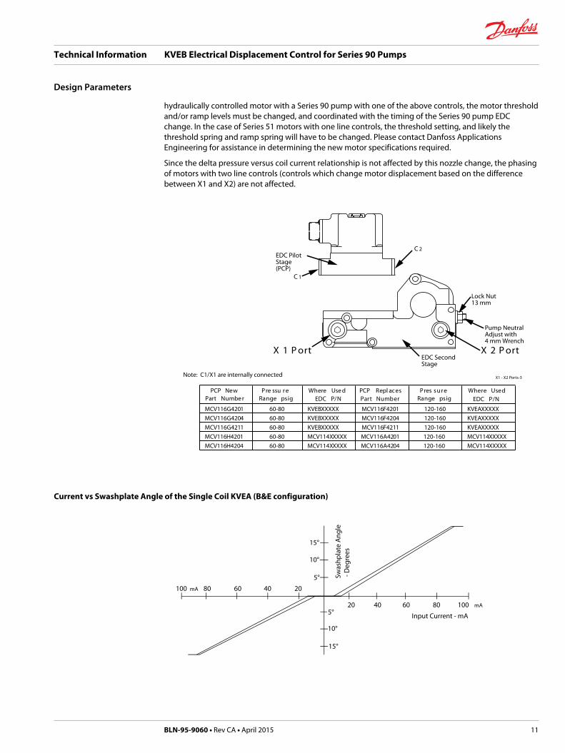
EDC PilotStage(PCP)
C 2
C 1
Lock Nut13 mm
Pump NeutralAdjust with4 mm Wrench
EDC SecondStage
troP 2 XtroP 1 X
Note: C1/X1 are internally connected
PCP New Pre ssu re Where Use d PCP Repl aces Pres sure Where UsedPart Numbe r
MCV116G4201 60-80 KVEBXXXXX MCV116F4201 120-160 KVEAXXXXXMCV116G4204 60-80 KVEBXXXXX MCV116F4204 120-160 KVEAXXXXXMCV116G4211 60-80 KVEBXXXXX MCV116F4211 120-160 KVEAXXXXXMCV116H4201 60-80 MCV114XXXXX MCV116A4201 120-160 MCV114XXXXXMCV116H4204 60-80 MCV114XXXXX MCV116A4204 120-160 MCV114XXXXX
Range psig EDC P/N Part Number Range psig EDC P/N
X1 - X2 Ports-3
Current vs Swashplate Angle of the Single Coil KVEA (B&E configuration)
15°
10°
5°
100 mA 80 60 40 20
20 40 60 80 100 mA
15°
10°
5°
Swas
hpla
te A
ngle
- D
egre
e s
Input Current - mA
Technical Information KVEB Electrical Displacement Control for Series 90 Pumps
Design Parameters
BLN-95-9060 • Rev CA • April 2015 11
Precautions when driving dual coil PCPs with a PWM driver
Danfoss dual coil PCPs are constructed in such a manner that magnetic flux generated in the circuit flowsthrough the windings of both coils. This phenomenon is basic to the torque motor technology used. Thisis different from some magnetic actuators, such as most proportional valves, that have two distinctlyseparate magnetic circuits. Since the flux generated in one coil flows through the other coil, the deviceoperates like, and in fact is, a transformer. This fact is generally insignificant when the coils are driven withdc currents, such as when the device is driven from a potentiometric control handle or from dc currentdrivers such as the valve drivers in Danfoss DC2 and SUSMIC microcontrollers. Many controllers are set upto drive proportional solenoids through Pulse Width Modulation (PWM). These controls send anoscillating pulse width modulated dc current to the coil. This design has the advantages of providingdither to the actuator and, in some cases, can simplify the electronics since they operate in a digitalmode. This can reduce heat output from the device.
Trade-offs or unwanted side effects:
Items 1 through 3 apply to all electrohydraulic actuators. Items 4 and 5 relate more specifically to PCPs.1. The pulsing current generates unwanted electromagnetic radiation, which can interfere with related
devices.2. The actuators are generally responsive to current. PWM valve drivers are generally low impedance
voltage drives. As the coils heat up the resistance changes (typically by as much as 50%), thus alteringthe response of the device. For given PWM frequency and duty cycle, both peak and average currentinto the driven coil may strongly affect the coil’s L/R (inductance/resistance) time constant,potentially reducing both accuracy and linearity. The effects vary considerably with valve type andwith temperature and are quite different between Danfoss MCV116 and MCV110. PWM drivers oftenrequire “current feedback” to maintain sufficient accuracy as the temperature varies over theoperating range.
3. Some controllers are designed to diagnose shorts or opens in the output circuit. The PWM-inducedvoltage can affect some common detection schemes.
4. In the case of the PCP, a PWM signal is just like an alternating current applied to the primary of atransformer. A voltage is induced in the secondary coil proportional to the turns ratio of the coils lesslosses in the magnetic circuit. If the secondary coil is open circuited, there is no effect since no currentflows, and hence no magnetic field is generated. However, if current is allowed to flow in thesecondary coil, it flows in a direction which will reduce the output of the actuator.
5. Most electronic drivers will conduct current when back driven with excessive voltages. One exampleis a drive that contains non-linear devices such as diodes or zener diodes for re-circulatory currents.The induced voltages may be sufficient to cause these devices to conduct thereby causing currentflow in the non-driven coil.
In position control systems where the control drives toward null this generally is not a problem.However, in propel systems, especially dual path propel systems, the change in output velocity couldbe severe limitation. In some cases filters can be designed to correct the problem. A limitation offilters is this adds a lag in the circuit which will adversely affect high response systems. Also it isimpossible to design one filter to fit all applications.
In summary, the ability to drive the Danfoss PCP depends on many circumstances which must beunderstood and accounted for by the user.
Technical Information KVEB Electrical Displacement Control for Series 90 Pumps
Design Parameters
12 BLN-95-9060 • Rev CA • April 2015

Theory of Operation
A command source such as a joystick, control handle or electronic controller applies current signals tothe pilot stage of the KVEB Electrical Displacement Control, which results in flow out of the pump. Theinput current commands the pilot’s torque motor stage, a bridge network consisting of an armaturemounted on a torsion pivot and suspended in the air gap of a magnetic field. Two permanent magnetspolarized together with two pole pieces form a frame for the magnetic bridge. At null the armature iscentered in the air gaps between the magnets’ opposing poles by the equivalence of their magneticforces and the null adjust centering springs. As the input differential current rises to the dual coils, theend of the armature becomes biased either north or south, depending on the magnitude of the currentdifferential. The resulting armature movement is determined by the amperage of control current, thespring constant and the differential pressure feedback forces, explained below. See the SchematicDiagram for a complete system illustration.
The magnetic bridge output, flapper torque, in turn controls the hydraulic bridge ratio. At null, theflapper is centered between two nozzles. Upstream from each nozzle is an orifice which provides anominal pressure drop when the system is at null. Between the nozzle and the orifice on each side is acontrol port. As the torque motor shifts the flapper away from one nozzle toward the other, a differentialcontrol pressure results, the high side being the one nearer the flapper. Fluid pressure rises on this sideand moves the flapper back towards null. When the torque output from the motor equals the torqueoutput from the pressure feedback, the pilot system is in equilibrium. It is this pressure feedback thatmakes the pilot a stand-alone closed loop pressure control valve. The pilot stage is silicone oil filled forprotection against the environment and for proper valve operation.
The second stage of the EDC uses a unique spool-barrel feedback arrangement that serves to separatethe null deadband from the feedback, giving both safety against null drift and quick dynamic response tocommand changes.
The second stage’s null adjust is set with a feedback spring compressed to a 16 psi threshold (measuredat the center of the hysteresis loop), which is the amount of differential pressure required to begin tomove the actuator spool one direction or the other. The threshold is a factory setting. By tightening orloosening the main null adjust screw, the fixed deadband is adjusted so that the pump starts to strokewith equal output current on either side of null.
As differential control pressure input from the pilot rises beyond the 16 psi deadband (KVEBB and KVEBEmodels), the spool moves in one direction or the other, opening one of the control ports to supply chargepressure to the pump’s servo-cylinders, moving the swashplate. As the swashplate moves, the linkagefollows, moving the barrel in the opposite direction of the spool’s original motion. The barrel’s feedbackmovement tends to drive the spool back toward neutral through its internal feedback spring. Oil returnsfrom the servo cylinders through the spool to the case.
Technical Information KVEB Electrical Displacement Control for Series 90 Pumps
Operation
BLN-95-9060 • Rev CA • April 2015 13

Schematic Diagram
Technical Information KVEB Electrical Displacement Control for Series 90 Pumps
Operation
14 BLN-95-9060 • Rev CA • April 2015

KVEB - EDC
Pum
p si
ze
Pilo
t
Product
K V E B
Configuration
Code Current range Remarks
A 4-20 (Single coil)
B 14-85 (Dual coil)
C 14-85 (Dual coil) High response, no pressure limiter (PL) orifices,annular housing
Pump size
Code Description
05 55 cc
07 75 cc
10 100 cc
13 130 cc S/N
14 130 cc S/N
18 180 cc or 250 cc
Pilot
Code Description
02 MS connector (14-85 mA)
04 Packard connector (14-85 mA)
07 MS connector (4-20 mA)
09 Deutsch connector (14-85 mA)
Technical Information KVEB Electrical Displacement Control for Series 90 Pumps
Model Code
BLN-95-9060 • Rev CA • April 2015 15

Intrinsically Safe Control
In industrial processes where flammable materials are handled, any leak or spillage may lead to anexplosive atmosphere. To protect both property and personnel, precautions must be taken to ensure thatthis atmosphere cannot be ignited. The areas at risk are known as hazardous areas and the materials thatare commonly involved include crude oil and its derivatives, alcohol, natural and synthetic process starch,grain, fibers and dust.
Intrinsic safety is based on the principle of restricting the electrical energy available in hazardous-areacircuits such that any sparks or hot surfaces that may occur as a result of electrical faults are too weak tocause ignition. Factory mutual Research (FM) has approved the following model listed below for use inClass I, Division 1, Group C and D hazardous locations as defined by the National Electrical code, NEC500/505 when used with approved barriers. If a given application requires only Division 2 approval, aninline barrier may not be required.
As of June 2012, the controls listed above have also been approved for use in hazardous locations inaccordance with European Directive 60079-11. The example model code shown below lists theparameters that these controls have been qualified to meet.
ATEX l l - 1 - G - E X - i a - l l B - T 4Equipment group Temperature classification
T4 = 135 C
Gas group llB = Ethylene
Explosion Protected
Environment
P108 624E
Protection methodia = Intrinsically safe
Equipment category
ll = Non Mining
1 = Zone 0
G = Gas
Wiring Options
Common wiring styles are mentioned as follows: MS, Packard Weather-Pack, and Deutsch. The MSConnector (MS3102C14S-2P) has four pins. See the MS Connector Diagram for pin locations. See theElectrical Characteristics section for pump phasing. Mating connectors must be ordered separately. Forthe MS connector order part number K08106. The mating Packard connector is a bag assembly partnumber K03384, comprised of :• (4) 14-16 gauge sleeves• (4) 18-20 gauge sleeves• (1) plastic housing• (4) green cable seals• (accept 2 2-2, 8 mm wire diameter)• (4) gray cable seals (accept 2 81-3, 49 mm wire diameter)• (4) blue cable seals (accept 3 50-4, 21 mm wire diameter)
Assembling the Female Tower Connector
1. Isolate the wires that extend from the command source to the EDC.
2. Strip back the insulation 5.5 millimeters on both wires.
3. Push a ribbed cable seal over each of the wires with the smaller diameter shoulder of the seals towardthe wire tip. Select the pair of seals that fits tightly over the wires. The distance from the tip of the
Technical Information KVEB Electrical Displacement Control for Series 90 Pumps
Options
16 BLN-95-9060 • Rev CA • April 2015

wires of the first (nearest) rib should be 9.5 millimeters. Thus the insulation should just protrudebeyond the seal.
4. Select the larger of the two sets of pins, as measured at Dimension A (see the Dimension A drawing),if using 14-16 gauge wire. Choose the smaller if using 18-20 gauge. Place the wire into the socket sothat the seal edge is pushed through and extends slightly beyond the circular tabs that hold it inplace. Crimp in the locations shown in the Packard Connector Crimp drawing with a Packard12014254 crimp tool. The distance from the back of the tangs to the furthest rib may not exceed 19,5mm.
5. Manually insert the assembled wires into the back end (large hole) of the plastic housing. Push untilthe wire detents with an audible click, then pull back slightly to ensure proper seating (Observe theproper phasing of the wires when installing: Black wire to “A” hole, Red wire to “B”, Black to “C” andRed to “D”). Terminals may be removed from the connector bodies with a Packard 12014012 removaltool.
6. Swing the holder down into the detented position to trap the wires in the housing. The third ribshould be sealed into the housing.
7. Plug the shroud connector from the valve into the tower connector just constructed. They are sealedwith a quadruple plug seal over the quadruple barrel of the tower assembly. The two connectorhalves should detent into each other. See the Packard Connector Parts drawing.
Technical Information KVEB Electrical Displacement Control for Series 90 Pumps
Options
BLN-95-9060 • Rev CA • April 2015 17

Mounting Procedure
W Warning
Exercise care when placing the valve on a surface before mounting on a transmission. Dropping orotherwise forcefully setting the valve down may damage the pin.
Clean all external surfaces of the pump with steam or solvent. Remove the six hex head cap screws fromthe housing using a 5 mm internal hex wrench. Remove the manual control or plate from the pump.
Always install a new mounting gasket. If going from a manual control to an EDC the same mounting boltscan be used. If going from a blanking plate to an EDC new mounting bolts are required because of thedifferent lengths. To help avoid a mounting problem it may be necessary to order a mounting kit. SeeSeries 90 Parts Manuals for mounting kit numbers.
W Warning
The KVEB EDC cannot be hydraulically connected with another device through the servo ports (X1 andX2). Do not disconnect the SAE servo port fittings for this purpose. Doing so may cause the EDC to go onstroke. The fittings are to be used only for troubleshooting purposes. When hydraulic connections arerequired, such as for a staging function, the MCV114S must be used. Also an orifice (Danfoss orifice fittingpart number 9002875-0039) must be located in each of the hydraulic connections.
Installing the Control
1. Place a new gasket on the pump housing. If a charge pressure control orifice is used ensure that theorifice and spring are in the proper position in the control.
2. While setting the control into position, engage the pin on the control linkage into the mating hole inthe link attached to the pump swashplate.
3. Check pin engagement can be checked by:a) Move control assembly left and right from center position, slight resistance will be noted if
properly engaged.b) Place a finger under the control connector and lift away form pump housing.
If control tilts away more than approximately 1/4 to 3/8 of an inch, the pin is not engaged.
4. Repeat steps 2 and 3 in case of non engagement.
W Warning
Ensure positive pin engagement. Failure to do so may result in unintended vehicle movement.
Location of Seal Washer on 180, and 250 cc Pump EDCsP108 628E
Technical Information KVEB Electrical Displacement Control for Series 90 Pumps
Mounting the Control
18 BLN-95-9060 • Rev CA • April 2015

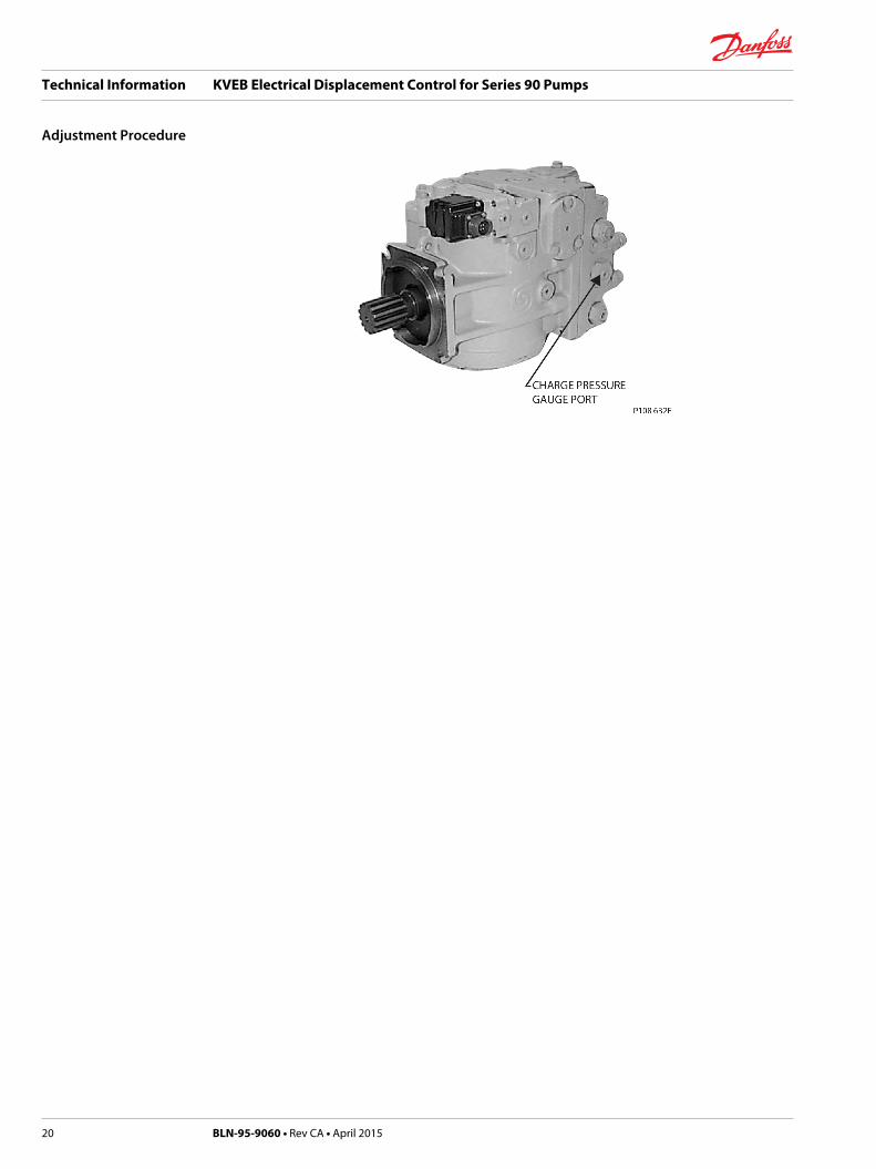
Pump Neutral Adjustment
Use the following procedure to bring the pump to neutral once the electrical displacement control hasbeen mounted.
1. Install a 600 psi gauge into the charge pressure gauge port on the pump. See the Pump Port Locationdrawing.
2. Using a 13 mm wrench, loosen the hex lock nut on the null adjustment screw. See the Dimensiondrawings.
3. Disconnect the electrical source at the connector.
4. Start the prime mover and run at low idle.
W Warning
To adjust neutral requires operating the pump. Take the necessary safety precautions, such as havingunnecessary personnel stand away from the machine. Maximum system pressure may occur uponstart-up, and the machine may move. Ensure that the operator is not in a position to be injuredshould the machine move.
5. Warm the system up for several minutes to bleed air.
6. Slowly increase the prime mover speed to rated rpm.
7. If the transmission operates as indicated by motor shaft rotation, reduce speed to idle. Using a 4 mminternal hex wrench, slowly turn the null adjustment screw clockwise or counterclockwise until thetransmission does not operate. Repeat step 6. Note that charge pressure should drop with forward orreverse stroking of the pump swashplate due to the shifting of the shuttle valve in the motormanifold. Slowly turn the null adjustment screw clockwise until charge pressure decreases.
8. If the transmission operates as indicated by motor shaft rotation, reduce speed to idle. Using a 4 mminternal hex wrench, slowly turn the null adjustment screw clockwise or counterclockwise until thetransmission does not operate. Repeat step 6. Note that charge pressure should drop with forward orreverse stroking of the pump swashplate due to the shifting of the shuttle valve in the motormanifold. Slowly turn the null adjustment screw clockwise until charge pressure decreases.
9. If the transmission operates as indicated by motor shaft rotation, reduce speed to idle. Using a 3 mminternal hex wrench, slowly turn the null adjustment screw clockwise or counterclockwise until thetransmission does not operate. Repeat step 6. Note that charge pressure should drop with forward orreverse stroking of the pump swashplate due to the shifting of the shuttle valve in the motormanifold. Slowly turn the null adjustment screw clockwise until charge pressure decreases.
10. With a 4 mm internal hex wrench, slowly turn the null adjustment screw counterclockwise, observingthe wrench angle rotation, until charge pressure decreases again (charge pressure will rise in neutraland drop when going into stroke).
11. Turn the adjustment screw clockwise half the amount of the turn observed in step 8. This should bethe center of neutral.
12. Hold the adjustment screw and securely tighten the hex lock nut on the adjustment screw to 14-18foot-pounds. Note that if a motor is used that does not have a manifold, neutral should be adjusted(steps 8 - 10) by observing the motor shaft rotation without a load.
13. Stop the prime mover.
14. Reconnect the electrical signal source.
15. Run the system briefly to ensure that it operates proportionally on both sides of null. Swashplatemovement can be verified by watching motor shaft rotation without a load.
Technical Information KVEB Electrical Displacement Control for Series 90 Pumps
Adjustment Procedure
BLN-95-9060 • Rev CA • April 2015 19
Technical Information KVEB Electrical Displacement Control for Series 90 Pumps
Adjustment Procedure
20 BLN-95-9060 • Rev CA • April 2015
Pump Fails to Stroke Properly
If the pump does not reach its expected output flow with the proper input electrical signal whenmeasured across the coils (approximately 2 to 2.5 Vdc and 12 to 15 Vdc for configuration A), the followingshould be checked:
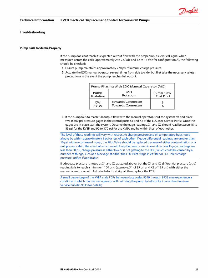
1. Ensure pump maintains approximately 270 psi minimum charge pressure.2. Actuate the EDC manual operator several times from side to side, but first take the necessary safety
precautions in the event the pump reaches full output.
Pump Phasing With EDC Manual Operator (MO)
Pump MORotation
Pump FlowtroP tuOnoitatoR
CW Towards ConnectorTowards Connector
BAWCC
3. If the pump fails to reach full output flow with the manual operator, shut the system off and place
two 0-500 psi pressure gages in the control ports X1 and X2 of the EDC (see Service Parts). Once thegages are in place start the system. Observe the gage readings. X1 and X2 should read between 45 to85 psi for the KVEB and 90 to 170 psi for the KVEA and be within 5 psi of each other.
The level of these readings will vary with respect to charge pressure and oil temperature but shouldalways be within approximately 5 psi or less of each other. If gage differential readings are greater than10 psi with no command signal, the Pilot Valve should be replaced because of either contamination or anull pressure shift, the effect of which would likely be pump creep in one direction. If gage readings areless than 80 psi, charge pressure is either low or is not getting to the EDC, which could be caused by anumber of things, such as a blockage at either the EDC Pilot Stage inlet filter or EDC inlet (chargepressure) orifice if applicable.
If adequate pressure is noted at X1 and X2 as stated above, but the X1 and X2 differential pressure (psid)reading fails to reach a minimum 100 psid (example, X1 of 35 psi and X2 of 135 psi) with either themanual operator or with full rated electrical signal, then replace the PCP.
A small percentage of the KVEA style PCPs between date codes 9549 through 9753 may experience acondition in which the manual operator will not bring the pump to full stroke in one direction (seeService Bulletin 9833 for details).
Technical Information KVEB Electrical Displacement Control for Series 90 Pumps
Troubleshooting
BLN-95-9060 • Rev CA • April 2015 21

75cc, 100cc, 130cc, 180cc and 250cc pumps - EDC
P108 630E
Control Linkage
Spacer(130, 180 cc)
MS ConnectorOption
PackardConnectorOption
54,90 mm2.16 in
29,20 mm1.15 in
11,70 mm REF0.46 in REF
201,0 mm7.9 in
138,18 mm5.44 in
89,41 mm3.52 in
55,37 mm2.18 in
38,07 mm1.42 in31,62 mm
1.245 in
12,20 mm0.48 in
8,60 mm0.34 in
103,45 mm4.073 in
49,78 mm1.96 in
144,22 mm5.56 in 169,67 mm
6.68 in185,70 mm7.31 in
108,46 mm4.27 in
9,70 mm0.38 in
Neutral Adjust
55cc pumps - EDC
P108 631E
ControlLinkage
MS ConnectorOption
PackardConnectorOption
54,90 mm2.16 in
29,20 mm1.15 in
13,00 mm REF0.51 in REF
138,18 mm5.44 in
6 x 7,14 mm DIA6 x .281 in DIA
89,41 mm3.52 in
55,37 mm2.18 in38,07 mm
1.42 in30,99 mm
1.22 in
181,60 mm7.15 in
12,20 mm0.48 in
5,6 mm0.22 in
44,70 mm1.76 in
99,06 mm3.90 in
131,06 mm5.16 in
96,70 mm3.81 in
153,42 mm6.04 in
166,12 mm6.54 in
9,70 mm0.38 in
Neutral Adjust
Technical Information KVEB Electrical Displacement Control for Series 90 Pumps
Installation Drawings
22 BLN-95-9060 • Rev CA • April 2015

Technical Information KVEB Electrical Displacement Control for Series 90 Pumps
BLN-95-9060 • Rev CA • April 2015 23

Technical Information KVEB Electrical Displacement Control for Series 90 Pumps
24 BLN-95-9060 • Rev CA • April 2015

Technical Information KVEB Electrical Displacement Control for Series 90 Pumps
BLN-95-9060 • Rev CA • April 2015 25

Danfoss Power Solutions is a global manufacturer and supplier of high-quality hydraulic andelectronic components. We specialize in providing state-of-the-art technology and solutionsthat excel in the harsh operating conditions of the mobile off-highway market. Building onour extensive applications expertise, we work closely with our customers to ensureexceptional performance for a broad range of off-highway vehicles.
We help OEMs around the world speed up system development, reduce costs and bringvehicles to market faster.
Danfoss – Your Strongest Partner in Mobile Hydraulics.
Go to www.powersolutions.danfoss.com for further product information.
Wherever off-highway vehicles are at work, so is Danfoss. We offer expert worldwide supportfor our customers, ensuring the best possible solutions for outstanding performance. Andwith an extensive network of Global Service Partners, we also provide comprehensive globalservice for all of our components.
Please contact the Danfoss Power Solution representative nearest you.
Local address:
Danfoss Power Solutions GmbH & Co. OHGKrokamp 35D-24539 Neumünster, GermanyPhone: +49 4321 871 0
Danfoss Power Solutions ApSNordborgvej 81DK-6430 Nordborg, DenmarkPhone: +45 7488 2222
Danfoss Power Solutions (US) Company2800 East 13th StreetAmes, IA 50010, USAPhone: +1 515 239 6000
Danfoss Power Solutions(Shanghai) Co., Ltd.Building #22, No. 1000 Jin Hai RdJin Qiao, Pudong New DistrictShanghai, China 201206Phone: +86 21 3418 5200
Danfoss can accept no responsibility for possible errors in catalogues, brochures and other printed material. Danfoss reserves the right to alter its products without notice. This also applies toproducts already on order provided that such alterations can be made without changes being necessary in specifications already agreed.All trademarks in this material are property of the respective companies. Danfoss and the Danfoss logotype are trademarks of Danfoss A/S. All rights reserved.
BLN-95-9060 • Rev CA • April 2015 www.danfoss.com © Danfoss A/S, 2015
Products we offer:
• Bent Axis Motors
• Closed Circuit Axial PistonPumps and Motors
• Displays
• Electrohydraulic PowerSteering
• Electrohydraulics
• Hydraulic Power Steering
• Integrated Systems
• Joysticks and ControlHandles
• Microcontrollers andSoftware
• Open Circuit Axial PistonPumps
• Orbital Motors
• PLUS+1® GUIDE
• Proportional Valves
• Sensors
• Steering
• Transit Mixer Drives
Comatrolwww.comatrol.com
Schwarzmüller-Inverterwww.schwarzmueller-inverter.com
Turolla www.turollaocg.com
Valmovawww.valmova.com
Hydro-Gearwww.hydro-gear.com
Daikin-Sauer-Danfosswww.daikin-sauer-danfoss.com