kv8 ecu datasheet - garage 7 · 2019-03-25 · 8.2 efi relay control ... b7 injection channel 7 b24...
TRANSCRIPT

Z
KV
8
PRODUCT
DATASHEET
Rev 1.2
Emtron KV8 ECU

KV8 ECU DATASHEET WWW.EMTRON.WORLD
© EMTRON AUSTRALIA PTY LTD JANUARY 2019 1
Contents
1.0 General ................................................................................................................................. 2
2.0 Outputs ................................................................................................................................ 3
3.0 Inputs ................................................................................................................................... 4
4.0 Lambda ................................................................................................................................. 5
5.0 Knock Control ....................................................................................................................... 5
6.0 Voltage and Ground Supplies .............................................................................................. 6
7.0 Communications .................................................................................................................. 6
8.0 KV8 Pinout ............................................................................................................................ 7
8.1 Important Notes .......................................................................................................................... 11
8.2 EFI Relay Control ......................................................................................................................... 12
9.0 Software ............................................................................................................................. 13
10.0 Ordering Information ....................................................................................................... 13
Appendix A – KV8 ECU Pinout Drawing (Rev2) ........................................................................ 14
Appendix B – Lambda Sensor Pinout ....................................................................................... 15
Appendix C – KV Series ECU Wiring – A21 ............................................................................... 16
Appendix D – KV Series Ethernet Wiring – A24 ....................................................................... 17
Appendix E – KV Series EFI Relay Wiring – A31 ....................................................................... 18

KV8 ECU DATASHEET WWW.EMTRON.WORLD
© EMTRON AUSTRALIA PTY LTD JANUARY 2019 2
1.0 General
Emtron’s KV8 is a wire in ECU with extreme flexibility. Industry leading I/O count will ensure you do not have to make any sacrifices when configuring your engine and vehicle. This ECU will support up to 8 Channels of fuel and 8 Channels fully sequential Ignition. Every KV8 is housed in a durable billet Aluminium enclosure and includes up to 32MB permanent memory for on board logging, 4-channel oscilloscope function, DBW control up to 2 channels, dual on-board LSU4.9 Lambda controllers, dual digital Knock control, Ethernet communications and 3 axis G-force sensing to name a few.
Power Supply
▪ Operating voltage: 6.0 to 22.0 Volts DC (ECU shutdowns at 24.0V)
▪ Operating current: 390mA at 14.0V (excluding sensor and load currents)
▪ Reverse battery protection via external fuse
▪ “Smart” battery transient protection
Operating Temperature ▪ Max operating range: -30 to 110°C (-22 to 230°F)
▪ Recommended operating range: -30 to 85°C (-22 to 185°F)
Physical
▪ Aluminium 6061 grade CNC billet enclosure ▪ Enclosure size 134 mm x 162 mm x 27 mm ▪ Weight: 730g ▪ Connector system: 120-way Super Seal waterproof connectors with gold plated contacts
o Pin diameter: 1 mm o Current rating: maximum 15A per pin (wire gauge dependant) o Connector A: 26 pin Key 2 Super Seal o Connector B: 34 pin Key 2 Super Seal o Connector C: 34 pin Key 1 Super Seal o Connector D: 26 pin Key 1 Super Seal
Internal ▪ Dual 100MHz processors
▪ 500Mb DDR RAM (0.5Gb)
▪ 32MB ECU logging memory
o Over 1200 channels available
o 1Hz to 500Hz logging rate
▪ Oscilloscope 4-channel function with 32MB storage
o Sampling at 100k samples/second
o Includes Crank and Cam sensor inputs
o Includes Digital inputs 1-4
▪ On-Board barometric pressure sensor
o Range 40 - 115.0 kPa
▪ 3-Axis accelerometer
o 16-Bit resolution
o +2g/+4g/+8g dynamically selectable full-scale
o Output data rate 500Hz

KV8 ECU DATASHEET WWW.EMTRON.WORLD
© EMTRON AUSTRALIA PTY LTD JANUARY 2019 3
2.0 Outputs
8x Port Injector Outputs—high or low ohm ▪ Flyback Voltage Clamp 70V
▪ Independent Saturated or Peak & Hold control per channel
▪ 8A Peak, 4A hold, 10A Limit Injector Control
▪ Outputs can be used for ground switching, 6A Continuous, 10A Limit
▪ All outputs are short circuit and over current protected
▪ No Flywheel diodes (external diode(s) required for VVT control)
8x Ignition Outputs ▪ Open collector outputs with Logic Level outputs
▪ Adjustable Ignition drive current (35mA or 70mA)
▪ Outputs can be used for Auxiliary ground switching, 1A Continuous, 3A Limit
▪ All outputs are short circuit and over current protected
▪ No Flywheel diodes (external diode(s) required for VVT control)
▪ Ignitor must be used between ECU and coil
16x Auxiliary Outputs ▪ Variable Valve Timing (VVT) and Variable Valve Timing Electric (VTiE), Drive by Wire (DBW)
up to 2 throttle bodies, dual boost control, gearshift solenoids, stepper motor and many more.
▪ All outputs have PWM control, maximum frequency = 15 kHz ▪ Flywheel diodes integrated into all outputs
o Auxiliary 1-8 Flywheel to the “ECU Supply” pin D1 connector D o Auxiliary 9-12 Flywheel to the “ECU 9-12 Supply” pin D20 connector D o Auxiliary 13-16 Flywheel to the “ECU 13-16 Supply” pin D2 connector D
▪ All outputs are short circuit and over current protected Low Side Drivers
o Auxiliary 1-4: Low Side 4A continuous, 6A peak modulated, 8A limit o Auxiliary 5-8: Low Side 2.5A continuous, 4A peak modulated, 5A limit High Side Drivers o Auxiliary 1-8: High Side 4A continuous, 9A limit
Half Bridge Drivers o Auxiliary 9-12: Half Bridge 5A continuous and 8A limit. Can be used as Low Side, High
Side or together for DC motor control (DBW up to 2x channels) o Auxiliary 13-16: Half Bridge 15.0A continuous (pin limited). Can be used as Low Side or
High Side.
1x EFI Relay Output ▪ Low Side Driver for relay control. Current limited to 200mA (Output will switch ON when
Ignition Switch Input (D15) is greater than 4V).
1x Analog Output Buffered ▪ Voltage range 0.0 - 5.0V, output current 100mA
1x Shield Output
▪ Connection for Trigger and Knock shielded cables. Short to battery protection
KV8 ECU DATASHEET WWW.EMTRON.WORLD
© EMTRON AUSTRALIA PTY LTD JANUARY 2019 4
3.0 Inputs 16x Analog Voltage/Temperature Inputs.
▪ Fully configurable including custom calibrations
▪ Switchable 1k ohm pull-up resistors on ANV 7-12 (available on 6 channels)
▪ Accepts a 0.0 - 5.000V analog input range. Resolution is 1.22mV (12-Bit)
▪ Input Impedance 100k Ohms to ground
▪ 160Hz Low pass filter
8x Digital/Speed Inputs (DI 1 - 8) ▪ Frequency range from 0.0Hz up the 30.0kHz on all 8 channels
▪ Magnetic and hall/optical effect sensor compatible with programable trigger edge(s)
▪ Independent programable frequency-based arming threshold control, range 0.0 - 12.0V
▪ Wheel speed, output shaft speed, turbo speed and other frequency-based signals
▪ VVT position(s) up to 4 channels available on DI 1- 4.
▪ Accepts a 0.0 - 20.0V analog input. Effective resolution is 4.88mV (10-Bit)
▪ On/Off switched inputs: AC request, launch enable, cruise switch, table control switching etc
with programable switch-based arming threshold control, range 0.0 - 20.0V
▪ Switchable 4k7 ohm pull-up resistors on all 8 channels to 10.0V
▪ Maximum/Minimum input signal amplitude +/- 80V
6x Digital/Switched Inputs (DI 9 - 14)
▪ On/Off switched inputs: AC request, Launch enable, cruise switch, table control switching etc
with programable switch-based arming threshold control, range 0.0 - 20.0V
▪ Accepts a 0.0 -20.0 V analog input. Effective resolution is 19.61mV (8-Bit)
▪ Switchable 4k7 ohm pull-up resistors on all 6 channels to 10.0V
1x Dedicated Ignition Switch Input
▪ 6.0 - 20.0V input used for EFI Relay Control. (With input > 4V the EFI Relay output (D9) will
switch ON)
2x Crank Index and Sync Engine Decoding Inputs
▪ Magnetic and Hall effect sensor compatible with programable trigger edge(s)
▪ “True” zero crossing detection on magnetic signals for precise engine position decoding.
▪ Programmable independent arming threshold control from 0.1V to 12.0V
▪ Switchable 4k7 ohm pull-up resistor to 5V
▪ OEM patterns supported
▪ Maximum input signal amplitude +/- 80V
▪ Input Impedance 39k ohms to ground
KV8 ECU DATASHEET WWW.EMTRON.WORLD
© EMTRON AUSTRALIA PTY LTD JANUARY 2019 5
4.0 Lambda
This ECU supports on-board dual Lambda controllers using the Bosch LSU4.9 wide band oxygen sensor.
2x Lambda channels supporting the Bosch LSU 4.9 sensor ▪ Using Bosch integrated circuit technology for precise sensor control
▪ Nernst cell temperature measurement for dynamic PID closed loop heater control
▪ Lambda range: 0.580 La to 10.000 La
▪ Diagnostics available for each pin and includes, Short to ground, Short to Vbat, Open Load
5.0 Knock Control
This ECU supports dual Knock control using inputs from a piezoelectric sensor. Each knock input is fully differential, giving superior common-mode noise rejection in the harsh automotive environment.
2x Knock Inputs ▪ 2 Independent knock input channels
▪ Using Bosch, Digital Knock Integrated Circuit Technology with programmable digital filter
coefficients
▪ Center frequency configurable from 500Hz - 25kHz
▪ Bandwidth window from 100Hz - 5kHz
▪ Digital filter window; Hamming or Blackman
▪ Gain control(x1, x2, x4, x8)
▪ Cylinder selectable knock input
▪ Knock control available on ALL Ignition modes (Direct, Wasted, Distributor etc)

KV8 ECU DATASHEET WWW.EMTRON.WORLD
© EMTRON AUSTRALIA PTY LTD JANUARY 2019 6
6.0 Voltage and Ground Supplies 1x ECU Supply Input
▪ 15.0A Max (pin limited) ▪ 6V - 22.0V Range ▪ Supplies ECU power ▪ Supplies Auxiliary 1-8 High Side Drivers
1x Auxiliary 9-12 Supply Input
▪ 15.0A Max (pin limited) ▪ Power supply for Auxiliary channels 9 -12. (See KV Series Power Distribution Wiring - A10.pdf
for more information on how this should be wired)
1x Auxiliary 13-16 Supply Input
▪ 15.0A Max (pin limited) ▪ Power supply for Auxiliary channels 13 -16. See KV Series Power Distribution Wiring -
A10.pdf for more information on how this should be wired)
2x 5.0V Sensor Supply
▪ 5V Vref1 output current 400mA ▪ 5V Vref2 output current 400mA ▪ Accuracy: +/- 1.0% at 25 °C ▪ Short circuit, Reverse Battery Protection, Thermal overload protection
▪ Operating temperature range -40°C ~ 125°C
1x 8.0V Sensor Supply ▪ Output current 600mA ▪ Accuracy: +/- 1.0% at 25 °C ▪ Short circuit, Reverse battery protection, Thermal overload protection ▪ Operating temperature range -40°C ~ 125°C
4x ECU Main Grounds
▪ 15.0A per pin, total 60A
2x Sensor 0V Reference
• Analog Sensor 0V Reference with short to battery protection
NOTE: The Sensor 0V Reference pin(s) are specialised ground outputs for all analog sensors. Connect direct to the sensor 0V pin, DO NOT connect to the Engine Block or ECU Ground.
7.0 Communications ▪ 1x High Speed Ethernet 100Mbps for tuning software connection ▪ 2x CAN 2.0B 1Mbps/ 6 Channels per node, total 128 messages
KV8 ECU DATASHEET WWW.EMTRON.WORLD
© EMTRON AUSTRALIA PTY LTD JANUARY 2019 7
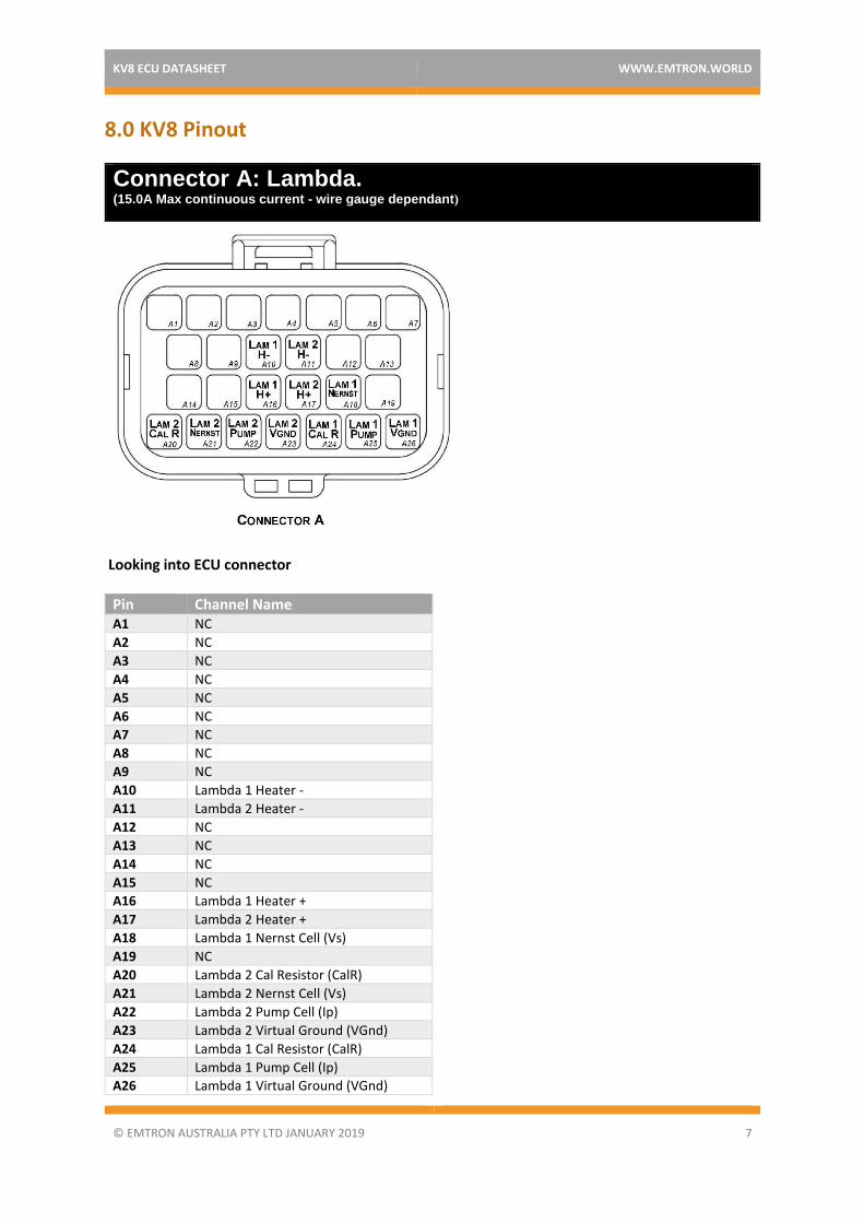
8.0 KV8 Pinout
Looking into ECU connector
Pin Channel Name A1 NC
A2 NC
A3 NC
A4 NC
A5 NC
A6 NC
A7 NC
A8 NC
A9 NC
A10 Lambda 1 Heater -
A11 Lambda 2 Heater -
A12 NC
A13 NC
A14 NC
A15 NC
A16 Lambda 1 Heater +
A17 Lambda 2 Heater +
A18 Lambda 1 Nernst Cell (Vs)
A19 NC
A20 Lambda 2 Cal Resistor (CalR)
A21 Lambda 2 Nernst Cell (Vs)
A22 Lambda 2 Pump Cell (Ip)
A23 Lambda 2 Virtual Ground (VGnd)
A24 Lambda 1 Cal Resistor (CalR)
A25 Lambda 1 Pump Cell (Ip)
A26 Lambda 1 Virtual Ground (VGnd)
Connector A: Lambda. (15.0A Max continuous current - wire gauge dependant)

KV8 ECU DATASHEET WWW.EMTRON.WORLD
© EMTRON AUSTRALIA PTY LTD JANUARY 2019 8
Connector B: Auxiliary Outputs /Fuel/Ignition/Ground (15.0A Max continuous current - wire gauge dependant)
Looking into ECU connector
Pin Channel Name Pin Channel Name B1 Injection Channel 1 B18 Auxiliary Output 9
B2 Injection Channel 2 B19 Auxiliary Output 10
B3 Injection Channel 3 B20 Auxiliary Output 11
B4 Injection Channel 4 B21 Auxiliary Output 12
B5 Injection Channel 5 B22 Auxiliary Output 13
B6 Injection Channel 6 B23 Auxiliary Output 14
B7 Injection Channel 7 B24 Auxiliary Output 15
B8 Injection Channel 8 B25 Auxiliary Output 16
B9 ECU Ground B26 Ignition Channel 1
B10 Auxiliary Output 1 B27 Ignition Channel 2
B11 Auxiliary Output 2 B28 Ignition Channel 3
B12 Auxiliary Output 3 B29 Ignition Channel 4
B13 Auxiliary Output 4 B30 Ignition Channel 5
B14 Auxiliary Output 5 B31 Ignition Channel 6
B15 Auxiliary Output 6 B32 Ignition Channel 7
B16 Auxiliary Output 7 B33 Ignition Channel 8
B17 Auxiliary Output 8 B34 ECU Ground
KV8 ECU DATASHEET WWW.EMTRON.WORLD
© EMTRON AUSTRALIA PTY LTD JANUARY 2019 9
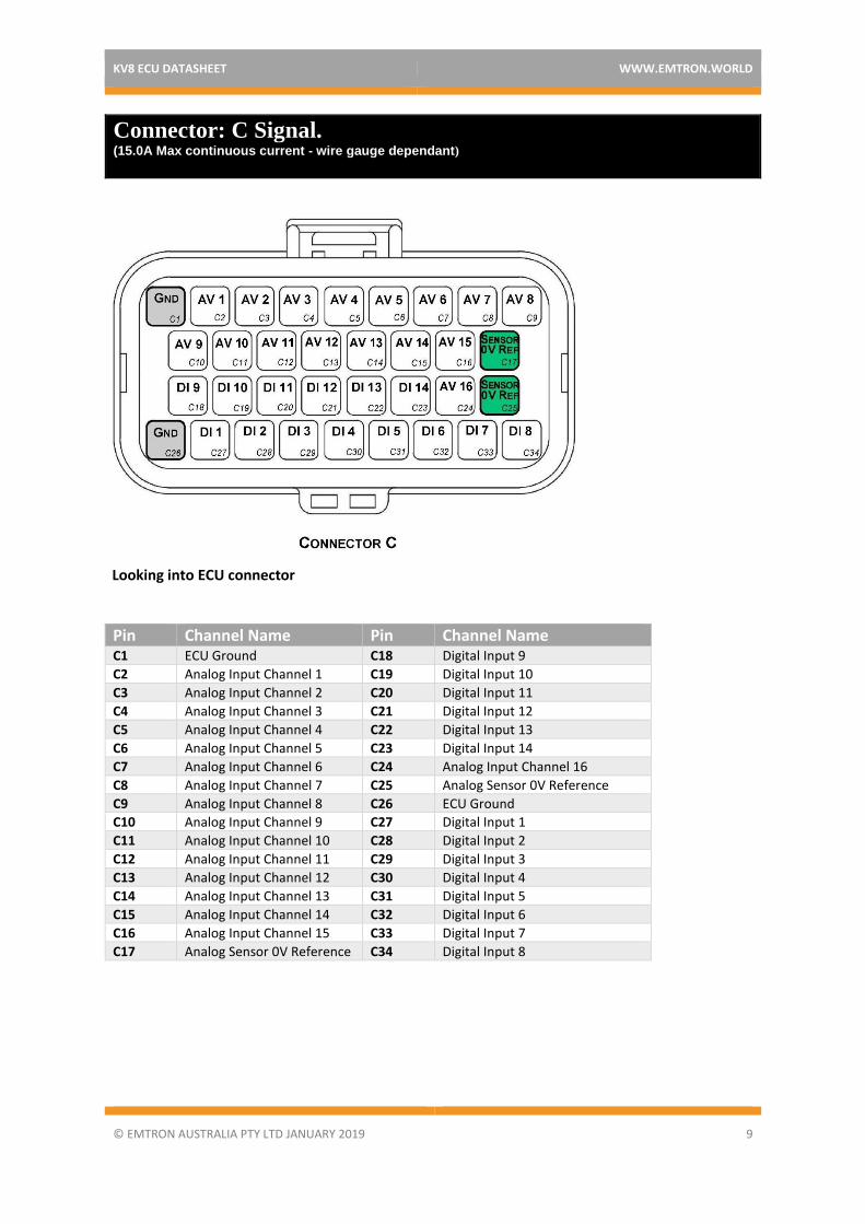
Connector: C Signal. (15.0A Max continuous current - wire gauge dependant)
Looking into ECU connector
Pin Channel Name Pin Channel Name C1 ECU Ground C18 Digital Input 9
C2 Analog Input Channel 1 C19 Digital Input 10
C3 Analog Input Channel 2 C20 Digital Input 11
C4 Analog Input Channel 3 C21 Digital Input 12
C5 Analog Input Channel 4 C22 Digital Input 13
C6 Analog Input Channel 5 C23 Digital Input 14
C7 Analog Input Channel 6 C24 Analog Input Channel 16
C8 Analog Input Channel 7 C25 Analog Sensor 0V Reference
C9 Analog Input Channel 8 C26 ECU Ground
C10 Analog Input Channel 9 C27 Digital Input 1
C11 Analog Input Channel 10 C28 Digital Input 2
C12 Analog Input Channel 11 C29 Digital Input 3
C13 Analog Input Channel 12 C30 Digital Input 4
C14 Analog Input Channel 13 C31 Digital Input 5
C15 Analog Input Channel 14 C32 Digital Input 6
C16 Analog Input Channel 15 C33 Digital Input 7
C17 Analog Sensor 0V Reference C34 Digital Input 8
KV8 ECU DATASHEET WWW.EMTRON.WORLD
© EMTRON AUSTRALIA PTY LTD JANUARY 2019 10
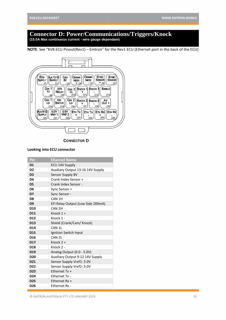
Connector D: Power/Communications/Triggers/Knock (15.0A Max continuous current - wire gauge dependant)
NOTE: See “KV8 ECU Pinout(Rev1) – Emtron” for the Rev1 ECU (Ethernet port in the back of the ECU)
Looking into ECU connector
Pin Channel Name D1 ECU 14V Supply
D2 Auxiliary Output 13-16 14V Supply
D3 Sensor Supply 8V
D4 Crank Index Sensor +
D5 Crank Index Sensor -
D6 Sync Sensor +
D7 Sync Sensor -
D8 CAN 1H
D9 EFI Relay Output (Low Side 200mA)
D10 CAN 2H
D11 Knock 1 +
D12 Knock 1 -
D13 Shield (Crank/Cam/ Knock)
D14 CAN 1L
D15 Ignition Switch Input
D16 CAN 2L
D17 Knock 2 +
D18 Knock 2 -
D19 Analog Output (0.0 - 5.0V)
D20 Auxiliary Output 9-12 14V Supply
D21 Sensor Supply Vref1: 5.0V
D22 Sensor Supply Vref2: 5.0V
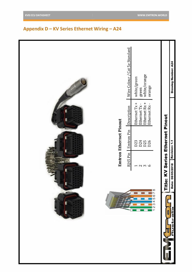
D23 Ethernet Tx +
D24 Ethernet Tx -
D25 Ethernet Rx +
D26 Ethernet Rx -

KV8 ECU DATASHEET WWW.EMTRON.WORLD
© EMTRON AUSTRALIA PTY LTD JANUARY 2019 11
8.1 Important Notes
Auxiliary Output Channels 13-16
These are high current Half bridge drivers which switch either to ground or 14V i.e. they do not have a high impedance or OFF state. When the ECU is powered OFF these Auxiliary Channels by default will be switching to ground. This means:
1) Solenoids or relays connected to these outputs should not use a constant or hot battery feed.
2) During the ECU powerup sequence, any solenoid or relay connected to these outputs should have a managed power feed to avoid momentary switching during powerup.
Analog Sensor 0V Reference (Pin C17, C25)
These pins should be connected directly to the 0V (Ground) pin on any low current analog sensor, for example Pressure or Temperature.
• DO NOT connect the ECU pins C17, C25 directly to the Engine Block or ECU Ground. These are dedicated and specialised ground outputs for all analog channels and should be connected directly to the sensor.
• DO NOT connect frequency-based sensors to these pins; for example, an Ethanol content sensor. The sensor 0V pin should be connected to the ECU ground.
Half Bridge Driver Power Supply Inputs (Pin D20, D2)
Pin D20 is a dedicated power supply for Auxiliary Channels 9-12. Power must be supplied to this pin for these channels to operate correctly. In non-DBW (Drive by Wire) applications the ECU Supply power can be shared, assuming the wire gauge has a sufficient rating for the current demand. In DBW applications power to this pin MUST come from an ECU controlled DBW Relay.
Pin D2 is a dedicated power supply for Auxiliary Channels 13-16. Power must be supplied to this pin for these Auxiliary channels to operate correctly.

KV8 ECU DATASHEET WWW.EMTRON.WORLD
© EMTRON AUSTRALIA PTY LTD JANUARY 2019 12
8.2 EFI Relay Control
This ECU supports the control of an EFI relay, allowing for management of its own power supply. To achieve this a dedicated Ignition Switch input and dedicated EFI Relay output are used.
When 12V is applied to the Ignition Switch input, the ECUs fixed internal circuity switches the EFI Relay output to ground allowing Main EFI relay to switch ON, suppling power to the ECU. This functionality is controlled at a hardware level, meaning 12V at the Ignition Switch input will ALWAYS make the EFI Relay output turn ON and switch to ground.
Once powered up the ECU takes control of the EFI Relay output, operating independent of the Ignition Switch input. When the Ignition Switch input goes low (turns OFF) this triggers the ECU to enter shutdown mode, but the ECU will only switch the Main relay OFF after all critical self-checks have been completed.
It is highly recommended the EFI Relay system be used. By allowing the ECU to control its power supply, when the Ignition Switch input turns OFF the ECU can firstly complete critical tasks before shutting itself down (for example, DBW Self calibration and ECU Logging data storage).
See Appendix E for specific wiring information.
KV8 ECU DATASHEET WWW.EMTRON.WORLD
© EMTRON AUSTRALIA PTY LTD JANUARY 2019 13
9.0 Software
Emtron’s comprehensive Emtune TM tuning software is used to connect to the ECU.
▪ Microsoft Windows TM 7 -10 compatible ▪ Free licence ▪ Memory requirements: 0.5GB RAM ▪ ECU connection using Ethernet, IPV4 protocol ▪ Tuning and data analysis ▪ PC and ECU data logging ▪ Live pause and data playback ▪ Advanced tuning functions ▪ Diagnostics ▪ Oscilloscope display
10.0 Ordering Information
Product Part Number Emtron KV8 ECU 1122-082 Emtron Ethernet Tuning Cable (1.5m) 553-15 Emtron Communications Cable, Superseal to Emtron Connector 200mm
533-02

KV8 ECU DATASHEET WWW.EMTRON.WORLD
© EMTRON AUSTRALIA PTY LTD JANUARY 2019 14
Appendix A – KV8 ECU Pinout Drawing (Rev2) NOTE: See “KV8 ECU Pinout(Rev1) – Emtron” for the Rev1 ECU (Ethernet port in the back of the ECU)

KV8 ECU DATASHEET WWW.EMTRON.WORLD
© EMTRON AUSTRALIA PTY LTD JANUARY 2019 15
Appendix B – Lambda Sensor Pinout

KV8 ECU DATASHEET WWW.EMTRON.WORLD
© EMTRON AUSTRALIA PTY LTD JANUARY 2019 16
Appendix C – KV Series ECU Wiring – A21
KV8 ECU DATASHEET WWW.EMTRON.WORLD
© EMTRON AUSTRALIA PTY LTD JANUARY 2019 17
Appendix D – KV Series Ethernet Wiring – A24

KV8 ECU DATASHEET WWW.EMTRON.WORLD
© EMTRON AUSTRALIA PTY LTD JANUARY 2019 18
Appendix E – KV Series EFI Relay Wiring – A31

KV8 ECU DATASHEET WWW.EMTRON.WORLD
© EMTRON AUSTRALIA PTY LTD JANUARY 2019 19
Emtron Australia Pty Ltd Unit 8, 36 Lidco Street Arndell Park NSW 2148 Australia
(See the www for contact information)
www.emtron.world www.emtronaustralia.com.au