kuka.touchsense 2 -...
TRANSCRIPT

KUKA System Technology
KUKA.TouchSense 2.0
For KUKA System Software 8.3
KUKA Roboter GmbH
Issued: 25.07.2013
Version: KST TouchSense 2.0 V1 en (PDF)
KUKA.TouchSense 2.0
2 / 53 Issued: 25.07.2013 Version: KST TouchSense 2.0 V1 en (PDF)
© Copyright 2013
KUKA Roboter GmbH
Zugspitzstraße 140
D-86165 Augsburg
Germany
This documentation or excerpts therefrom may not be reproduced or disclosed to third parties without the express permission of KUKA Roboter GmbH.
Other functions not described in this documentation may be operable in the controller. The user has no claims to these functions, however, in the case of a replacement or service work.
We have checked the content of this documentation for conformity with the hardware and software described. Nevertheless, discrepancies cannot be precluded, for which reason we are not able to guarantee total conformity. The information in this documentation is checked on a regular basis, how-ever, and necessary corrections will be incorporated in the subsequent edition.
Subject to technical alterations without an effect on the function.
Translation of the original documentation
KIM-PS5-DOC
Publication: Pub KST TouchSense 2.0 (PDF) en
Book structure: KST TouchSense 2.0 V1.2
Version: KST TouchSense 2.0 V1 en (PDF)
Contents
Contents
1 Introduction .................................................................................................. 5
1.1 Target group .............................................................................................................. 5
1.2 Industrial robot documentation ................................................................................... 5
1.3 Representation of warnings and notes ...................................................................... 5
1.4 Terms used ................................................................................................................ 6
2 Product description ..................................................................................... 7
2.1 Overview of KUKA.TouchSense ................................................................................ 7
2.2 Communication .......................................................................................................... 7
2.3 Workpiece search ...................................................................................................... 8
2.3.1 Single Touch mode ............................................................................................... 8
2.3.2 Double Touch mode ............................................................................................. 9
3 Safety ............................................................................................................ 11
4 Installation ................................................................................................... 13
4.1 System requirements ................................................................................................. 13
4.2 Installing or updating TouchSense ............................................................................. 13
4.3 Uninstalling TouchSense ........................................................................................... 14
5 Operation ...................................................................................................... 15
5.1 Menus ........................................................................................................................ 15
5.2 Status keys ................................................................................................................ 15
6 Configuration ............................................................................................... 17
6.1 Configuring TouchSense via the smartHMI ............................................................... 17
6.1.1 “General settings” tab ........................................................................................... 17
6.1.2 “Search dynamic” tab ............................................................................................ 18
6.1.3 “Sensor configuration” tab .................................................................................... 19
6.2 Configuring TouchSense with WorkVisual ................................................................. 19
6.2.1 Setting parameters ............................................................................................... 20
7 Programming ............................................................................................... 21
7.1 Instructions for programming ..................................................................................... 21
7.2 Preparation ................................................................................................................ 21
7.3 Inline form “Search” ................................................................................................... 21
7.3.1 Option window “Set new reference” ...................................................................... 23
7.3.2 Option window “Search parameter” ...................................................................... 24
7.4 Linked search ............................................................................................................. 25
7.4.1 Example of a linked search: searching for the position of a single-V butt weld .... 26
7.5 Programming a correction instruction ........................................................................ 27
7.5.1 Inline form “Corr” (1-dimensional) ......................................................................... 27
7.5.2 Inline form “Corr” (2-dimensional) ......................................................................... 28
7.5.3 Inline form “Corr” (3-dimensional) ......................................................................... 29
7.5.4 Inline form “Corr” (freely programmable) .............................................................. 30
7.5.4.1 Freely programmable correction – detailed explanation .................................. 32
7.5.5 Inline form “Corr Off” ............................................................................................. 33
7.5.6 Inline form “Check Point” ...................................................................................... 33
7.5.6.1 Option window “Position evaluation criteria” .................................................... 35
3 / 53Issued: 25.07.2013 Version: KST TouchSense 2.0 V1 en (PDF)

4 / 53
KUKA.TouchSense 2.0
8 Example programs ...................................................................................... 37
8.1 Example program with 3-dimensional correction ....................................................... 37
9 Messages ...................................................................................................... 39
9.1 Error messages ......................................................................................................... 39
10 KUKA Service ............................................................................................... 43
10.1 Requesting support ................................................................................................... 43
10.2 KUKA Customer Support ........................................................................................... 43
Index ............................................................................................................. 51
Issued: 25.07.2013 Version: KST TouchSense 2.0 V1 en (PDF)
1 Introduction
1 Introduction
1.1 Target group
This documentation is aimed at users with the following knowledge and skills:
Advanced knowledge of the robot controller system
Advanced KRL programming skills
1.2 Industrial robot documentation
The industrial robot documentation consists of the following parts:
Documentation for the manipulator
Documentation for the robot controller
Operating and programming instructions for the KUKA System Software
Documentation relating to options and accessories
Parts catalog on storage medium
Each of these sets of instructions is a separate document.
1.3 Representation of warnings and notes
Safety These warnings are relevant to safety and must be observed.
This warning draws attention to procedures which serve to prevent or remedy emergencies or malfunctions:
Notes These hints serve to make your work easier or contain references to further information.
For optimal use of our products, we recommend that our customers take part in a course of training at KUKA College. Information about the training program can be found at www.kuka.com or can be ob-
tained directly from our subsidiaries.
These warnings mean that it is certain or highly probable that death or severe injuries will occur, if no precautions
are taken.
These warnings mean that death or severe injuries may occur, if no precautions are taken.
These warnings mean that minor injuries may occur, if no precautions are taken.
These warnings mean that damage to property may oc-cur, if no precautions are taken.
These warnings contain references to safety-relevant information or general safety measures. These warnings do not refer to individual hazards or individual pre-
cautionary measures.
Procedures marked with this warning must be followed exactly.
5 / 53Issued: 25.07.2013 Version: KST TouchSense 2.0 V1 en (PDF)
6 / 53
KUKA.TouchSense 2.0
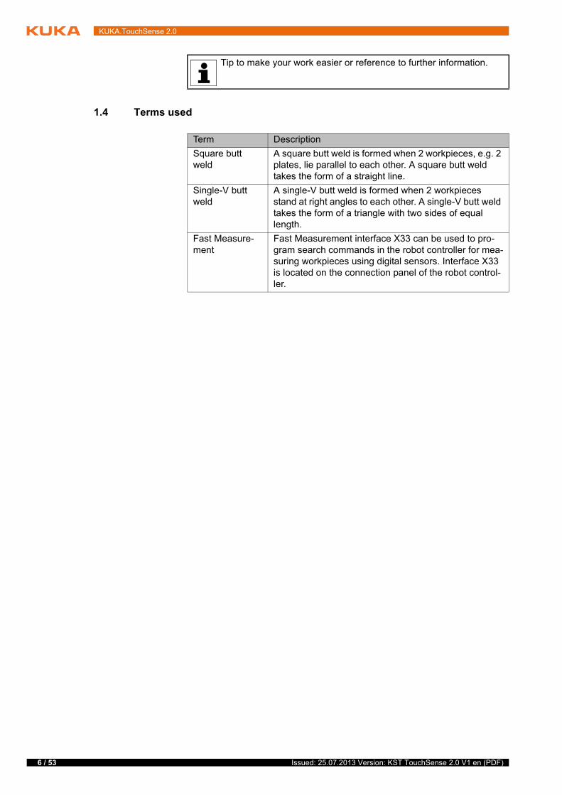
1.4 Terms used
Tip to make your work easier or reference to further information.
Term Description
Square butt weld
A square butt weld is formed when 2 workpieces, e.g. 2 plates, lie parallel to each other. A square butt weld takes the form of a straight line.
Single-V butt weld
A single-V butt weld is formed when 2 workpieces stand at right angles to each other. A single-V butt weld takes the form of a triangle with two sides of equal length.
Fast Measure-ment
Fast Measurement interface X33 can be used to pro-gram search commands in the robot controller for mea-suring workpieces using digital sensors. Interface X33 is located on the connection panel of the robot control-ler.
Issued: 25.07.2013 Version: KST TouchSense 2.0 V1 en (PDF)
2 Product description
2 Product description
2.1 Overview of KUKA.TouchSense
KUKA.TouchSense is an add-on technology package e.g. for welding applica-tions that require a high degree of dimensional accuracy. Correction of the originally programmed path is often necessary in order to compensate for de-viations in the shape or position of workpieces. This is possible with KU-KA.TouchSense.
Functional
principle
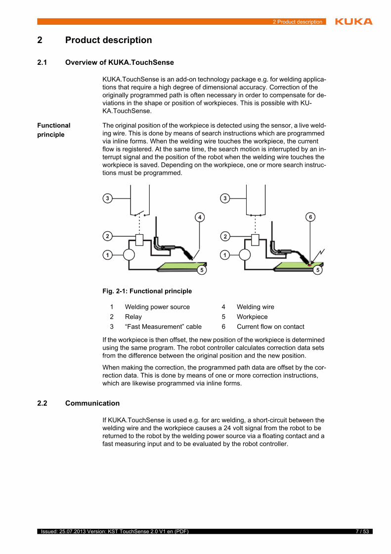
The original position of the workpiece is detected using the sensor, a live weld-ing wire. This is done by means of search instructions which are programmed via inline forms. When the welding wire touches the workpiece, the current flow is registered. At the same time, the search motion is interrupted by an in-terrupt signal and the position of the robot when the welding wire touches the workpiece is saved. Depending on the workpiece, one or more search instruc-tions must be programmed.
If the workpiece is then offset, the new position of the workpiece is determined using the same program. The robot controller calculates correction data sets from the difference between the original position and the new position.
When making the correction, the programmed path data are offset by the cor-rection data. This is done by means of one or more correction instructions, which are likewise programmed via inline forms.
2.2 Communication
If KUKA.TouchSense is used e.g. for arc welding, a short-circuit between the welding wire and the workpiece causes a 24 volt signal from the robot to be returned to the robot by the welding power source via a floating contact and a fast measuring input and to be evaluated by the robot controller.
Fig. 2-1: Functional principle
1 Welding power source 4 Welding wire
2 Relay 5 Workpiece
3 “Fast Measurement” cable 6 Current flow on contact
7 / 53Issued: 25.07.2013 Version: KST TouchSense 2.0 V1 en (PDF)
8 / 53
KUKA.TouchSense 2.0
2.3 Workpiece search
Overview There are two methods available for this:
Single Touch
(>>> 2.3.1 "Single Touch mode" Page 8)
Double Touch
(>>> 2.3.2 "Double Touch mode" Page 9)
2.3.1 Single Touch mode
This method can be used to determine the positional offset of a workpiece.
The robot moves the sensor from the start point along a defined search path. The search direction is defined by the Via point. The search motion is stopped when the sensor touches the workpiece.
The axis values determined during the search are saved as a correction data set. The robot then returns to the start point.
The search path must be programmed in such a way that both the original and new positions of the workpiece lie within the limits of the search motion and
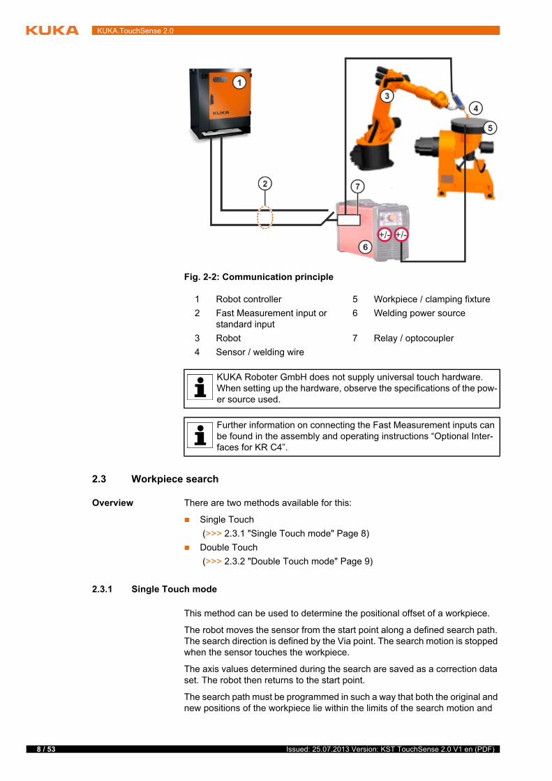
Fig. 2-2: Communication principle
1 Robot controller 5 Workpiece / clamping fixture
2 Fast Measurement input or standard input
6 Welding power source
3 Robot 7 Relay / optocoupler
4 Sensor / welding wire
KUKA Roboter GmbH does not supply universal touch hardware. When setting up the hardware, observe the specifications of the pow-er source used.
Further information on connecting the Fast Measurement inputs can be found in the assembly and operating instructions “Optional Inter-faces for KR C4”.
Issued: 25.07.2013 Version: KST TouchSense 2.0 V1 en (PDF)

2 Product description
can thus be detected. The search path is dependent on the search distance X, which is set in the Search Parameter option window.
The number of search instructions needed depends on the possible changes in position of the workpiece. Up to 3 search instructions are generally neces-sary (for the offset and rotation of each axis) in order to adapt a path to the changed position. In the case of unfavorable geometries or poor accessibility, the number of search motions can be extended as required.
2.3.2 Double Touch mode
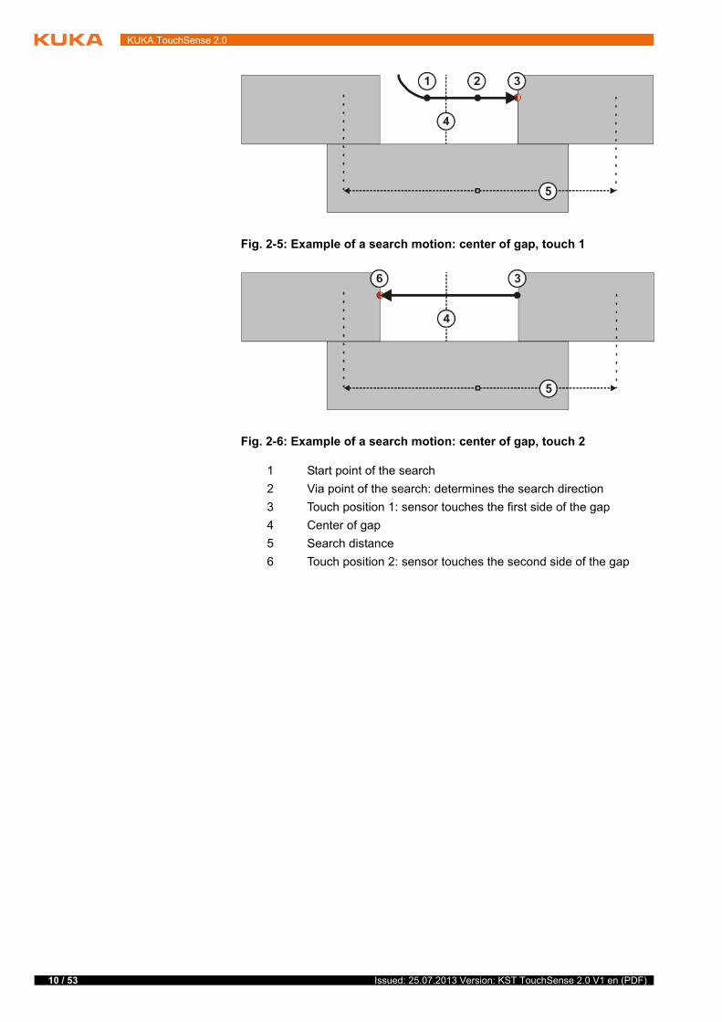
This method can be used to determine the center of a gap between 2 work-pieces, e.g. for a square butt weld.
The start point of the search lies within the gap. The search direction is defined by the Via point. The search motion is stopped when the sensor touches the side of the gap. The search is then started automatically in the opposite direc-tion. The search motion is stopped when the sensor touches the other side of the gap.
From the axis values determined during the search, the center of the gap is calculated and saved as a correction data set. The robot then returns to the start point.
The start point and the search path must be programmed in such a way that both the original and new positions of the gap lie within the limits of the search motion and can thus be detected. The search path is dependent on the search distance X, which is set in the Search Parameter option window.
Fig. 2-3: Example: search motion, original position of the workpiece
Fig. 2-4: Example: search motion, new position of the workpiece
1 Start point of the search
2 Via point of the search: determines the search direction
3 Touch position: sensor touches workpiece
4 Search distance
5 Workpiece
9 / 53Issued: 25.07.2013 Version: KST TouchSense 2.0 V1 en (PDF)
10 / 53
KUKA.TouchSense 2.0
Fig. 2-5: Example of a search motion: center of gap, touch 1
Fig. 2-6: Example of a search motion: center of gap, touch 2
1 Start point of the search
2 Via point of the search: determines the search direction
3 Touch position 1: sensor touches the first side of the gap
4 Center of gap
5 Search distance
6 Touch position 2: sensor touches the second side of the gap
Issued: 25.07.2013 Version: KST TouchSense 2.0 V1 en (PDF)

3 Safety
3 Safety
This documentation contains safety instructions which refer specifically to the software described here.
The fundamental safety information for the industrial robot can be found in the “Safety” chapter of the Operating and Programming Instructions for System In-tegrators or the Operating and Programming Instructions for End Users.
The “Safety” chapter in the operating and programming instructions of the KUKA System Software (KSS) must be observed. Death to per-sons, severe injuries or considerable damage to property may other-
wise result.
11 / 53Issued: 25.07.2013 Version: KST TouchSense 2.0 V1 en (PDF)

12 / 53
KUKA.TouchSense 2.0
Issued: 25.07.2013 Version: KST TouchSense 2.0 V1 en (PDF)

4 Installation
4 Installation
4.1 System requirements
Robot
controller
Hardware:
KR C4 with interface X33
Software:
KUKA System Software 8.3.2 or higher
Laptop/PC Software:
WorkVisual 3.0
The requirements for installation of WorkVisual are contained in the WorkVisual documentation.
4.2 Installing or updating TouchSense
Precondition “Expert” user group
Software on USB stick
Procedure 1. Connect the USB stick to the robot controller or smartPAD.
2. In the main menu, select Start-up > Additional software.
3. Press New software: The entry TouchSense must be displayed in the Name column and drive E:\ or K:\ in the Path column.
If not, press Refresh.
4. If the specified entries are now displayed, continue with step 5.
If not, the drive from which the software is being installed must be config-ured first:
Press the Configuration button. A new window opens.
Select a line in the Installation paths for options area.
Note: If the line already contains a path, this path will be overwritten.
Press Path selection. The available drives are displayed.
Select E:\. (If stick connected to the robot controller.)
Or select K:\. (If stick connected to the smartPAD.)
Press Save. The window closes again.
The drive only needs to be configured once and then remains saved for further installations.
5. Select the entry TouchSense and click on Install. Answer the request for confirmation with Yes.
6. Confirm the reboot prompt with OK.
7. Remove the stick.
8. Reboot the robot controller.
LOG file A LOG file is created under C:\KRC\ROBOTER\LOG.
It is advisable to archive all relevant data before updating a software package.
Recommendation: Always use KUKA sticks. Data may be lost if sticks from other manufacturers are used.
13 / 53Issued: 25.07.2013 Version: KST TouchSense 2.0 V1 en (PDF)
14 / 53
KUKA.TouchSense 2.0
4.3 Uninstalling TouchSense
Precondition “Expert” user group
Procedure 1. In the main menu, select Start-up > Additional software. All additional programs installed are displayed.
2. Select the entry TouchSense and click on Uninstall. Reply to the request for confirmation with Yes. Uninstallation is prepared.
3. Reboot the robot controller. Uninstallation is resumed and completed.
LOG file A LOG file is created under C:\KRC\ROBOTER\LOG.
It is advisable to archive all relevant data before uninstalling a soft-ware package.
Issued: 25.07.2013 Version: KST TouchSense 2.0 V1 en (PDF)

5 Operation
5 Operation
5.1 Menus
The following menus and commands are specific to this technology package:
Main menu:
Configuration > TouchSense
Menu sequence:
Commands > TouchSense
Search
Correction
Switch off correction
Check position correction
5.2 Status keys
Procedure Displaying the status keys:
In the main menu, select Configuration > Status keys > TouchSense.
Description The status keys are only available if the following conditions are met:
“Expert” user group
Operating mode T1 or T2
Program is selected
Submit interpreter running
The parameter TouchSense active is activated in the configuration
The enabling switch is pressed (only for status key Sensor On)
TouchSense is activated via the status key Option Off (only for status key Sensor On)
Status key Description
Status key Option Off (not pressed)
TouchSense is active. Search and correction are carried out.
Pressing the status key deactivates TouchSense.
Status key Option Off (pressed)
TouchSense is not active. Neither search nor correction is carried out.
Status key Force Mastering (pressed)
Remastering is active. At the next search routine, the posi-tion data of the workpiece will be saved as reference data. In the case of a reference run, the reference coordinates are recalculated. The reference coordinates of the previous mastering are overwritten.
Status key Force Mastering (not pressed)
Remastering is not active.
Pressing the status key activates remastering.
Status key Corr Off (not pressed)
Correction is not active.
15 / 53Issued: 25.07.2013 Version: KST TouchSense 2.0 V1 en (PDF)

16 / 53
KUKA.TouchSense 2.0
Status key Corr Off (not pressed)
Correction has been switched on and is now active.
Status key Corr Off (pressed)
Correction is deactivated and cannot be switched on via the program.
Or, if correction was switched on, it has been deactivated by means of this status key.
Status key Sensor On (pressed)
The sensor is switched on.
Status key Sensor On (pressed)
The sensor is switched on and the welding wire is touching the component.
Status key Sensor On (not pressed)
The sensor is switched off.
Pressing the status key switches the sensor on.
Status key Description
Issued: 25.07.2013 Version: KST TouchSense 2.0 V1 en (PDF)

6 Configuration
6 Configuration
6.1 Configuring TouchSense via the smartHMI
Precondition “Expert” user group
No program is selected.
Procedure 1. In the main menu, select Configuration > TouchSense.
2. Set the parameters on the tabs as required.
(>>> 6.1.1 "“General settings” tab" Page 17)
(>>> 6.1.2 "“Search dynamic” tab" Page 18)
(>>> 6.1.3 "“Sensor configuration” tab" Page 19)
3. Close the window. Respond to the request for confirmation asking whether the change should be saved by pressing Yes.
6.1.1 “General settings” tab
Parameter Description
TouchSense active Activate or deactivate TouchSense.
Activated: TouchSense is active; the TouchSense commands are executed.
Deactivated: TouchSense is inactive; the TouchSense commands are ignored.
Steps for messaging Set the messaging level.
Low: Only the most important messages are displayed, including safety messages.
Medium: The displayed messages enable a diagnosis to be carried out by the user.
High: The displayed messages enable a diagnosis to be carried out by the expert.
Default setting: Low
Note: Performance is highest with the setting Low, as every message is prepared and logged in the system.
Number of search or measurement repeats after error
If an error (e.g. component not found) occurs during a search or mea-surement, the robot controller automatically repeats the search up to the specified number of retries (as long as errors still occur). Following the last repetition, and depending on the setting of the parameter Display dialog in event of error, either a dialog message is generated or the program stops with an acknowledgement message.
0 … 5
Default setting: 0
Note: In the case of a search with welding wire, it is advisable to set this parameter to the value 0. Otherwise, the welding wire may bend in the case of a faulty search. If the search is repeated, this leads to incorrect measurement values.
Wait time before auto-matic repeat [s]
Before the repetitions configured under Number of search or mea-surement repeats after error, the robot controller waits for the time specified here.
0.3 … 2.00 s
Default setting: 0.3 s
17 / 53Issued: 25.07.2013 Version: KST TouchSense 2.0 V1 en (PDF)
18 / 53
KUKA.TouchSense 2.0
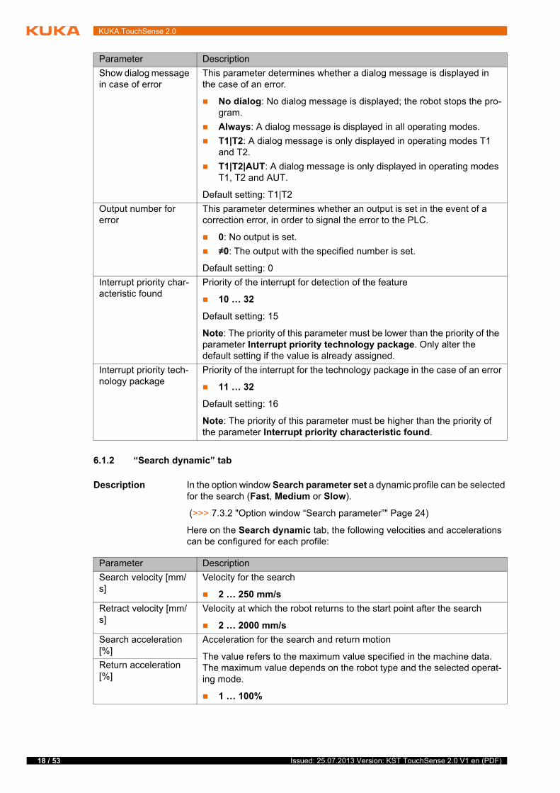
6.1.2 “Search dynamic” tab
Description In the option window Search parameter set a dynamic profile can be selected for the search (Fast, Medium or Slow).
(>>> 7.3.2 "Option window “Search parameter”" Page 24)
Here on the Search dynamic tab, the following velocities and accelerations can be configured for each profile:
Show dialog message in case of error
This parameter determines whether a dialog message is displayed in the case of an error.
No dialog: No dialog message is displayed; the robot stops the pro-gram.
Always: A dialog message is displayed in all operating modes.
T1|T2: A dialog message is only displayed in operating modes T1 and T2.
T1|T2|AUT: A dialog message is only displayed in operating modes T1, T2 and AUT.
Default setting: T1|T2
Output number for error
This parameter determines whether an output is set in the event of a correction error, in order to signal the error to the PLC.
0: No output is set.
≠0: The output with the specified number is set.
Default setting: 0
Interrupt priority char-acteristic found
Priority of the interrupt for detection of the feature
10 … 32
Default setting: 15
Note: The priority of this parameter must be lower than the priority of the parameter Interrupt priority technology package. Only alter the default setting if the value is already assigned.
Interrupt priority tech-nology package
Priority of the interrupt for the technology package in the case of an error
11 … 32
Default setting: 16
Note: The priority of this parameter must be higher than the priority of the parameter Interrupt priority characteristic found.
Parameter Description
Parameter Description
Search velocity [mm/s]
Velocity for the search
2 … 250 mm/s
Retract velocity [mm/s]
Velocity at which the robot returns to the start point after the search
2 … 2000 mm/s
Search acceleration [%]
Acceleration for the search and return motion
The value refers to the maximum value specified in the machine data. The maximum value depends on the robot type and the selected operat-ing mode.
1 … 100%
Return acceleration [%]
Issued: 25.07.2013 Version: KST TouchSense 2.0 V1 en (PDF)
6 Configuration
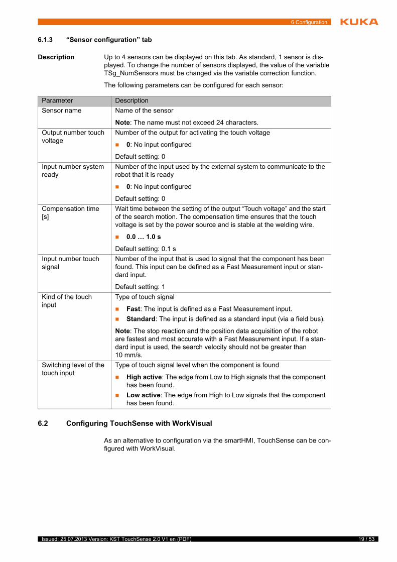
6.1.3 “Sensor configuration” tab
Description Up to 4 sensors can be displayed on this tab. As standard, 1 sensor is dis-played. To change the number of sensors displayed, the value of the variable TSg_NumSensors must be changed via the variable correction function.
The following parameters can be configured for each sensor:
6.2 Configuring TouchSense with WorkVisual
As an alternative to configuration via the smartHMI, TouchSense can be con-figured with WorkVisual.
Parameter Description
Sensor name Name of the sensor
Note: The name must not exceed 24 characters.
Output number touch voltage
Number of the output for activating the touch voltage
0: No input configured
Default setting: 0
Input number system ready
Number of the input used by the external system to communicate to the robot that it is ready
0: No input configured
Default setting: 0
Compensation time [s]
Wait time between the setting of the output “Touch voltage” and the start of the search motion. The compensation time ensures that the touch voltage is set by the power source and is stable at the welding wire.
0.0 … 1.0 s
Default setting: 0.1 s
Input number touch signal
Number of the input that is used to signal that the component has been found. This input can be defined as a Fast Measurement input or stan-dard input.
Default setting: 1
Kind of the touch input
Type of touch signal
Fast: The input is defined as a Fast Measurement input.
Standard: The input is defined as a standard input (via a field bus).
Note: The stop reaction and the position data acquisition of the robot are fastest and most accurate with a Fast Measurement input. If a stan-dard input is used, the search velocity should not be greater than 10 mm/s.
Switching level of the touch input
Type of touch signal level when the component is found
High active: The edge from Low to High signals that the component has been found.
Low active: The edge from High to Low signals that the component has been found.
19 / 53Issued: 25.07.2013 Version: KST TouchSense 2.0 V1 en (PDF)

20 / 53
KUKA.TouchSense 2.0
6.2.1 Setting parameters
Precondition A project is open.
The robot controller has been set as the active controller.
Procedure 1. Open the editor TouchSense Configuration: menu sequence Editors > Options packages > Configure TouchSense....
2. Set the parameters on the tabs as required.
(>>> 6.1.1 "“General settings” tab" Page 17)
(>>> 6.1.2 "“Search dynamic” tab" Page 18)
(>>> 6.1.3 "“Sensor configuration” tab" Page 19)
3. Save the settings.
Step Description
1 Install the TouchSense option package in WorkVisual.
2 Transfer the project from the robot controller to WorkVisual.
Precondition: TouchSense is installed on the robot controller.
Note: This project should be used for the configuration of TouchSense in WorkVisual, otherwise the entries installed on the robot controller by TouchSense could be lost when the project is transferred back to the robot controller (see step 4).
3 Configure TouchSense in the Editor TouchSense Configura-tion.
(>>> 6.2.1 "Setting parameters" Page 20)
4 Transfer the project from WorkVisual to the robot controller.
Note: During project transfer, the technology-specific files are copied to the robot controller and activated. If an earlier proj-ect has already been transferred, the files of this project are overwritten. It is therefore recommended to archive the files of the earlier project before transferring the new project.
Information about installing and managing option packages can be found in the WorkVisual documentation.
Information about bus configuration and project deployment can be found in the WorkVisual documentation.
Issued: 25.07.2013 Version: KST TouchSense 2.0 V1 en (PDF)

7 Programming
7 Programming
7.1 Instructions for programming
7.2 Preparation
The following questions must be considered in preparation for programming:
1. In what ways are the workpieces liable to be offset in relation to the refer-ence workpiece?
Linear offset along the length, width and/or height
And/or: Tilted along the length and/or width, and/or rotated in the plane
2. If only linear offsets are able to occur: Can the reference workpiece be cal-ibrated as a BASE?
3. At what points do measurements have to be carried out in order to detect the offsets?
4. Are these points accessible for the sensor?
5. Which CDx data of the measurement register the offset?
6. To what extent are the workpieces liable to be offset in relation to the ref-erence workpiece? Therefore, do the measurements have to be pro-grammed with or without a search?
7.3 Inline form “Search”
Description This instruction is used to measure the position of the workpiece.
The search is also suitable for robots with mathematically coupled external ax-es, or robots with a workpiece and a fixed tool (external TCP).
The external axis must be in position before starting the search. It may be moved into new positions for the next search procedure. If teaching with ex-ternal axes (mathematically coupled or otherwise), these must remain station-ary, i.e. only the 6 robot axes may be moved.
A search instruction is also a motion instruction (PTP, LIN, CIRC, SLIN or SCIRC). The search is initiated at the end point of this motion. As soon as the workpiece has been found, the robot is stopped. The position of the workpiece is saved and the robot moves back to the starting point (single touch).
An additional point must be taught for the search (Via point). This Via point de-fines the search direction. The maximum length of the search motion and other properties of the search are defined using the parameter list.
Programming a search instruction involves the following steps:
Saving the coordinates of the start point.
Saving the coordinates of the Via point.
Setting various parameters, e.g. search velocity.
Precondition A program is selected.
Operating mode T1 or T2
When a new program is created or an existing program is changed, a test run must be performed in T1 mode.
The programming descriptions refer to a sensor installed on the mounting flange unless stated otherwise. If a fixed sensor is used, the programming must be adapted accordingly.
21 / 53Issued: 25.07.2013 Version: KST TouchSense 2.0 V1 en (PDF)

22 / 53
KUKA.TouchSense 2.0
The welding wire must not be bent.
Preparation It is easier to program the search if the workpiece is positioned in the XY plane of a calibrated $BASE or parallel to $WORLD.
If the welding wire is bent or pushed back on contact with the workpiece, this will falsify the correction data. To reduce the risk of this occurring, it is recommended that the maximum search velocity is determined before pro-gramming the search.
Procedure 1. Select the menu sequence Commands > TouchSense > Search.
2. Select the motion type in the inline form.
3. Only if CIRC or SCIRC has been selected as the motion type:
Move the TCP to the position for the auxiliary point. Press Teach Aux.
4. Move the TCP to the position for the end point (= start point for the search). Press Touchup.
The start point must be approached in such a way that the welding wire is not perpendicular to the workpiece during the search, otherwise the resul-tant correction data will be falsified. Ideally, the welding wire should be po-sitioned at an angle of approx. 45° to the search direction at the start position.
5. Set the other parameters in the inline form.
6. Move the TCP to the position that is to be taught as the Via point. Press Touchup Via.
7. If the search instruction is to detect the original position of the workpiece (instead of the deviation from the original position), set the parameter to Yes in the option window Set new reference. The data are saved as ref-erence data.
(>>> 7.3.1 "Option window “Set new reference”" Page 23)
8. Set the desired parameters in the option window “Search parameter”.
(>>> 7.3.2 "Option window “Search parameter”" Page 24)
9. Save instruction with Cmd OK.
There is a risk of collisions if differently calibrated posi-tions are used in search instructions. When program-
ming search instructions, it must be ensured that teaching is carried out using either a robot tool or an external tool or an external kinematic system.
Fig. 7-1: Start position for search
Issued: 25.07.2013 Version: KST TouchSense 2.0 V1 en (PDF)
7 Programming
7.3.1 Option window “Set new reference”
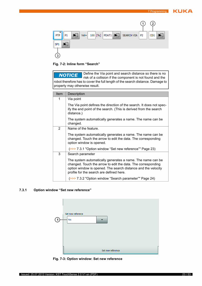
Fig. 7-2: Inline form “Search”
Define the Via point and search distance so there is no risk of a collision if the component is not found and the
robot therefore has to cover the full length of the search distance. Damage to property may otherwise result.
Item Description
1 Via point
The Via point defines the direction of the search. It does not spec-ify the end point of the search. (This is derived from the search distance.)
The system automatically generates a name. The name can be changed.
2 Name of the feature.
The system automatically generates a name. The name can be changed. Touch the arrow to edit the data. The corresponding option window is opened.
(>>> 7.3.1 "Option window “Set new reference”" Page 23)
3 Search parameter
The system automatically generates a name. The name can be changed. Touch the arrow to edit the data. The corresponding option window is opened. The search distance and the velocity profile for the search are defined here.
(>>> 7.3.2 "Option window “Search parameter”" Page 24)
Fig. 7-3: Option window: Set new reference
23 / 53Issued: 25.07.2013 Version: KST TouchSense 2.0 V1 en (PDF)
24 / 53
KUKA.TouchSense 2.0
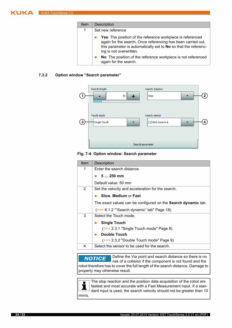
7.3.2 Option window “Search parameter”
Item Description
1 Set new reference
Yes: The position of the reference workpiece is referenced again for the search. Once referencing has been carried out, this parameter is automatically set to No so that the referenc-ing is not overwritten.
No: The position of the reference workpiece is not referenced again for the search.
Fig. 7-4: Option window: Search parameter
Item Description
1 Enter the search distance.
5 … 250 mm
Default value: 50 mm
2 Set the velocity and acceleration for the search.
Slow, Medium or Fast
The exact values can be configured on the Search dynamic tab.
(>>> 6.1.2 "“Search dynamic” tab" Page 18)
3 Select the Touch mode.
Single Touch
(>>> 2.3.1 "Single Touch mode" Page 8)
Double Touch
(>>> 2.3.2 "Double Touch mode" Page 9)
4 Select the sensor to be used for the search.
Define the Via point and search distance so there is no risk of a collision if the component is not found and the
robot therefore has to cover the full length of the search distance. Damage to property may otherwise result.
The stop reaction and the position data acquisition of the robot are fastest and most accurate with a Fast Measurement input. If a stan-dard input is used, the search velocity should not be greater than 10
mm/s.
Issued: 25.07.2013 Version: KST TouchSense 2.0 V1 en (PDF)

7 Programming
7.4 Linked search
Description With searches consisting of more than one search motion, there may be such a large deviation in one direction that a further search instruction no longer lo-cates the workpiece. This can be avoided by linking searches as illustrated in the following diagrams.
Linking the searches leads to a higher hit rate and greater accuracy. The linked search is suitable for all linear offsets and slight rotations.
Example
The second search command no longer locates the workpiece:
Remedy: Program a linked search. The second search command then takes into account the first change in position.
...LIN P1 TouchSense SEARCH VIA P2 CD1LIN P3 TouchSense SEARCH VIA P4 CD2TouchSense Corr 2D CD1 CD2...
Fig. 7-5: Original position
Fig. 7-6: New position, without linked search
...LIN P1 TouchSense SEARCH VIA P2 CD1TouchSense Corr 1D CD1LIN P3 TouchSense SEARCH VIA P4 CD2TouchSense Corr 2D CD1 CD2...
Fig. 7-7: New position and linked search
25 / 53Issued: 25.07.2013 Version: KST TouchSense 2.0 V1 en (PDF)
26 / 53
KUKA.TouchSense 2.0
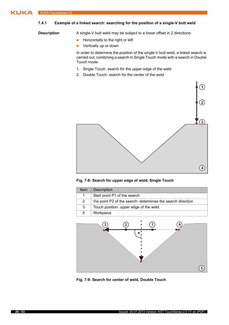
7.4.1 Example of a linked search: searching for the position of a single-V butt weld
Description A single-V butt weld may be subject to a linear offset in 2 directions:
Horizontally to the right or left
Vertically up or down
In order to determine the position of the single-V butt weld, a linked search is carried out, combining a search in Single Touch mode with a search in Double Touch mode.
1. Single Touch: search for the upper edge of the weld
2. Double Touch: search for the center of the weld
Fig. 7-8: Search for upper edge of weld, Single Touch
Item Description
1 Start point P1 of the search
2 Via point P2 of the search: determines the search direction
3 Touch position: upper edge of the weld
4 Workpiece
Fig. 7-9: Search for center of weld, Double Touch
Issued: 25.07.2013 Version: KST TouchSense 2.0 V1 en (PDF)
7 Programming
Example
7.5 Programming a correction instruction
7.5.1 Inline form “Corr” (1-dimensional)
Description This correction instruction is used if the workpiece has a linear offset in one direction:
Length
Width
or height
A correction instruction overwrites the data of a previous correction instruction.
Item Description
1 Start point P3 of the search
2 Via point P4 of the search: the search direction must be pro-grammed so that it is perpendicular to the upper edge of the weld.
3 Touch position 1: from this point, the search motion is started in the opposite direction.
4 Touch position 2
5 Workpiece
1 ...2 LIN P3 TouchSense SEARCH VIA P4 CD13 TouchSense Corr 1D CD14 LIN P1 TouchSense SEARCH VIA P2 CD25 TouchSense Corr 2D CD1 CD26 ...
Line Description
2 Search instruction for determining the center of the weld (Double Touch)
3 Correction instruction 1 dimensional: Correction of the hori-zontal offset of the weld
4 Search instruction for determining the upper edge of the weld (Single Touch)
5 Correction instruction 2 dimensional: Correction of the hori-zontal offset of the weld, linked to correction of the vertical off-set of the weld
6 … Weld program
If the workpieces are possibly inclined and/or rotated in relation to the reference workpiece, the correction in-
struction Corr Free must be used. The correction instructions Corr 1D, Corr 2D and Corr 3D can only be used to determine or correct linear offsets and not rotations or inclinations.
27 / 53Issued: 25.07.2013 Version: KST TouchSense 2.0 V1 en (PDF)
28 / 53
KUKA.TouchSense 2.0
Precondition All search instructions have been programmed.
Procedure 1. Select the menu sequence Commands > TouchSense > Correction.
2. Select 1D in the inline form.
7.5.2 Inline form “Corr” (2-dimensional)
Description This correction instruction is used if the workpiece has a linear offset in two directions:
Length
Width
or height
A correction instruction overwrites the data of a previous correction instruction. The following example is valid for an unlinked search.
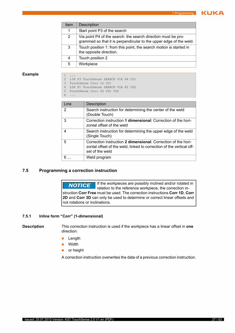
Fig. 7-10: Example: 1-dimensional offset
1 Original position 2 Offset position
Fig. 7-11: Inline form: Corr (1D)
Item Description
1 Enter the correction data set.
All correction data sets created in the current program can be entered.
Issued: 25.07.2013 Version: KST TouchSense 2.0 V1 en (PDF)

7 Programming
Precondition All search instructions have been programmed.
Procedure 1. Select the menu sequence Commands > TouchSense > Correction.
2. Select 2D in the inline form.
7.5.3 Inline form “Corr” (3-dimensional)
Description This correction instruction is used if the workpiece has a linear offset in all di-rections:
Length
Width
and height
A correction instruction overwrites the data of a previous correction instruction. The following example is valid for an unlinked search.
Fig. 7-12: Example: 2-dimensional offset
1 Original position 2 Offset position
Fig. 7-13: Inline form: Corr (2D)
Item Description
1, 2 Enter the correction data set.
All correction data sets created in the current program can be entered.
29 / 53Issued: 25.07.2013 Version: KST TouchSense 2.0 V1 en (PDF)
30 / 53
KUKA.TouchSense 2.0
Precondition All search instructions have been programmed.
Procedure 1. Select the menu sequence Commands > TouchSense > Correction.
2. Select 3D in the inline form.
7.5.4 Inline form “Corr” (freely programmable)
Description This correction instruction is used if the workpiece is rotated in one or more directions:
Length
Width
Height
The workpiece may additionally have a linear offset in the other directions.
A correction instruction overwrites the data of a previous correction instruction.
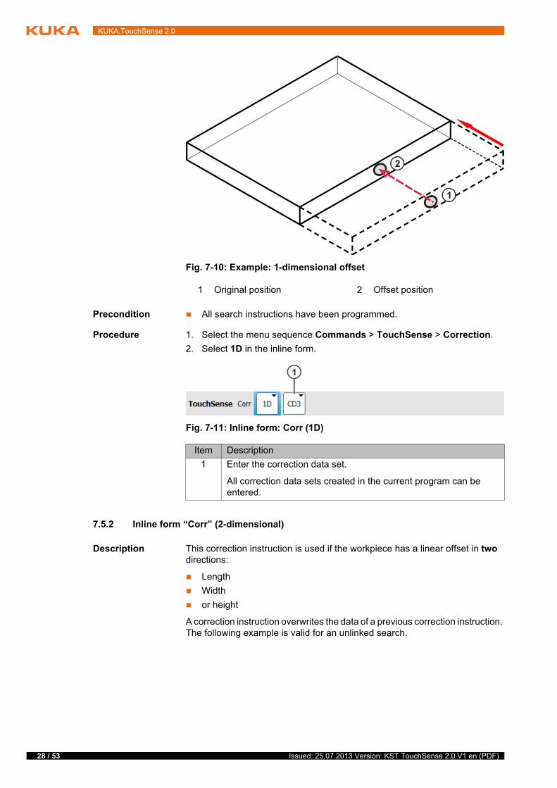
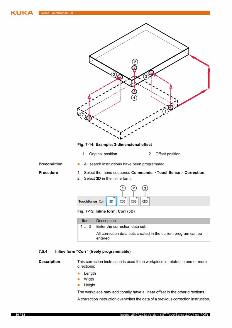
Fig. 7-14: Example: 3-dimensional offset
1 Original position 2 Offset position
Fig. 7-15: Inline form: Corr (3D)
Item Description
1 … 3 Enter the correction data set.
All correction data sets created in the current program can be entered.
Issued: 25.07.2013 Version: KST TouchSense 2.0 V1 en (PDF)
7 Programming
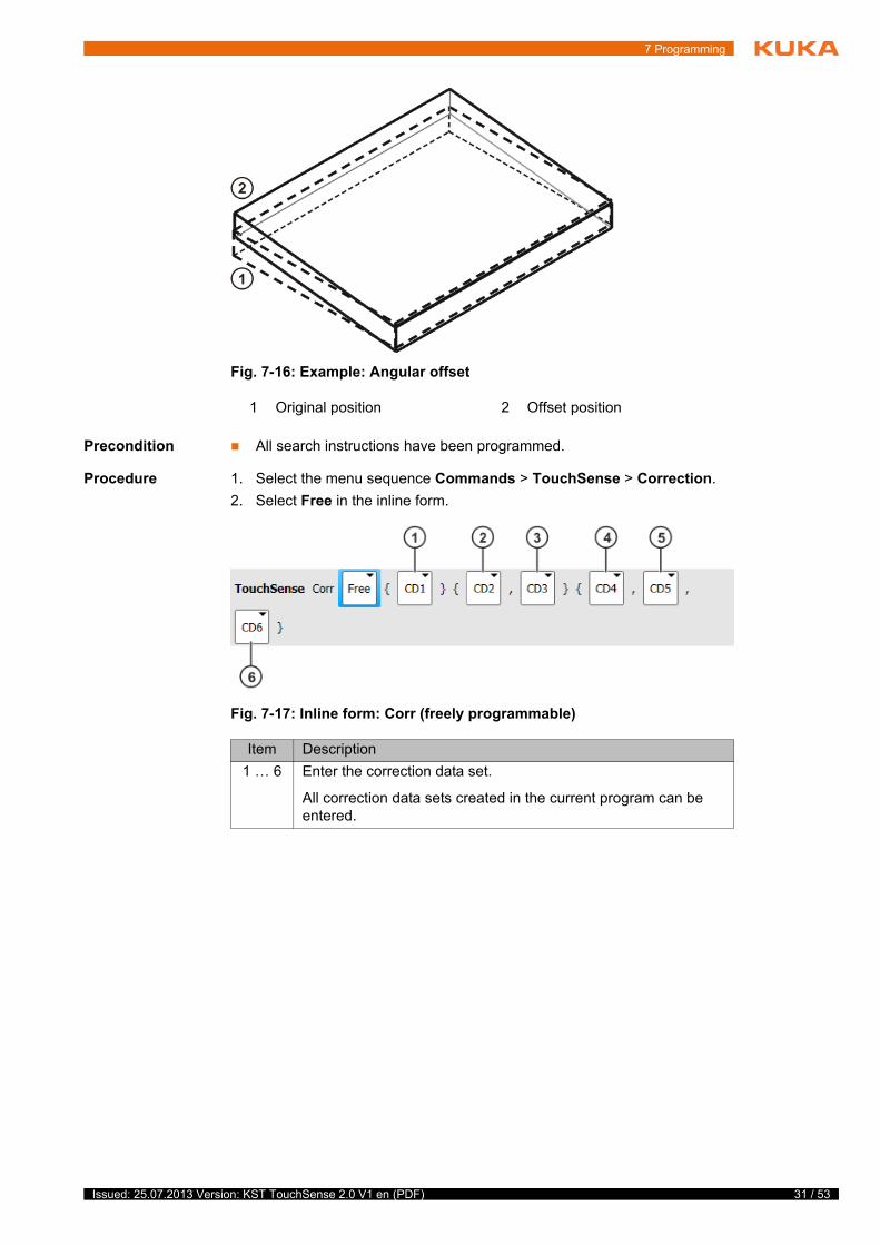
Precondition All search instructions have been programmed.
Procedure 1. Select the menu sequence Commands > TouchSense > Correction.
2. Select Free in the inline form.
Fig. 7-16: Example: Angular offset
1 Original position 2 Offset position
Fig. 7-17: Inline form: Corr (freely programmable)
Item Description
1 … 6 Enter the correction data set.
All correction data sets created in the current program can be entered.
31 / 53Issued: 25.07.2013 Version: KST TouchSense 2.0 V1 en (PDF)
32 / 53
KUKA.TouchSense 2.0
7.5.4.1 Freely programmable correction – detailed explanation
Description
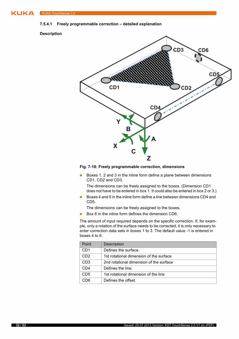
Boxes 1, 2 and 3 in the inline form define a plane between dimensions CD1, CD2 and CD3.
The dimensions can be freely assigned to the boxes. (Dimension CD1 does not have to be entered in box 1. It could also be entered in box 2 or 3.)
Boxes 4 and 5 in the inline form define a line between dimensions CD4 and CD5.
The dimensions can be freely assigned to the boxes.
Box 6 in the inline form defines the dimension CD6.
The amount of input required depends on the specific correction. If, for exam-ple, only a rotation of the surface needs to be corrected, it is only necessary to enter correction data sets in boxes 1 to 3. The default value -1 is entered in boxes 4 to 6.
Fig. 7-18: Freely programmable correction, dimensions
Point Description
CD1 Defines the surface.
CD2 1st rotational dimension of the surface
CD3 2nd rotational dimension of the surface
CD4 Defines the line.
CD5 1st rotational dimension of the line
CD6 Defines the offset.
Issued: 25.07.2013 Version: KST TouchSense 2.0 V1 en (PDF)
7 Programming
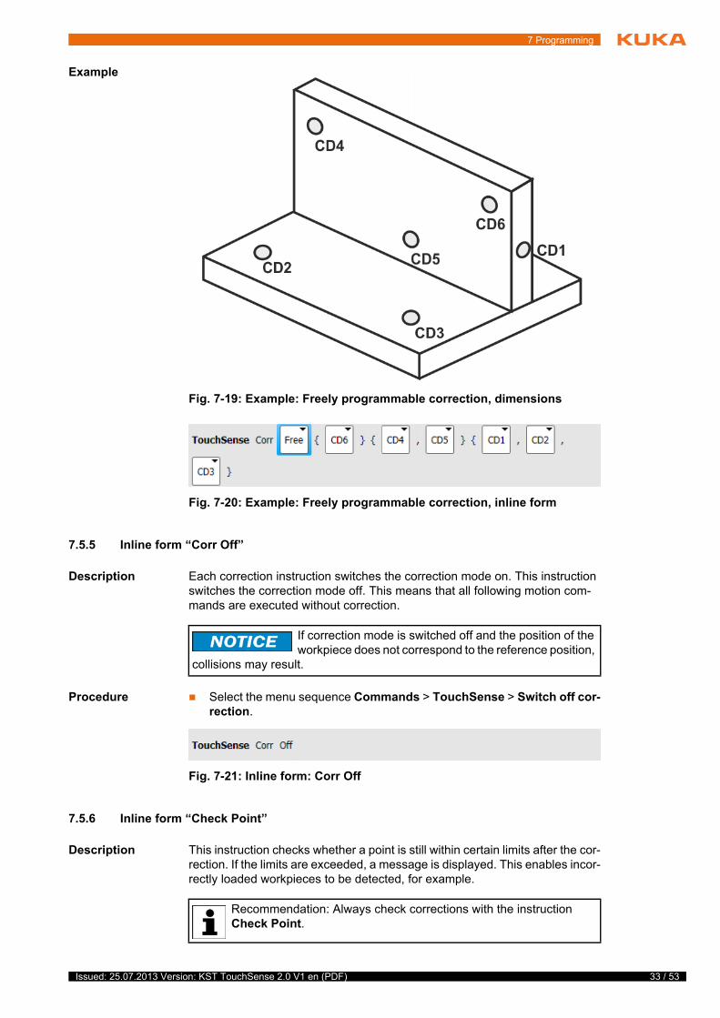
Example
7.5.5 Inline form “Corr Off”
Description Each correction instruction switches the correction mode on. This instruction switches the correction mode off. This means that all following motion com-mands are executed without correction.
Procedure Select the menu sequence Commands > TouchSense > Switch off cor-rection.
7.5.6 Inline form “Check Point”
Description This instruction checks whether a point is still within certain limits after the cor-rection. If the limits are exceeded, a message is displayed. This enables incor-rectly loaded workpieces to be detected, for example.
Fig. 7-19: Example: Freely programmable correction, dimensions
Fig. 7-20: Example: Freely programmable correction, inline form
If correction mode is switched off and the position of the workpiece does not correspond to the reference position,
collisions may result.
Fig. 7-21: Inline form: Corr Off
Recommendation: Always check corrections with the instruction Check Point.
33 / 53Issued: 25.07.2013 Version: KST TouchSense 2.0 V1 en (PDF)
34 / 53
KUKA.TouchSense 2.0
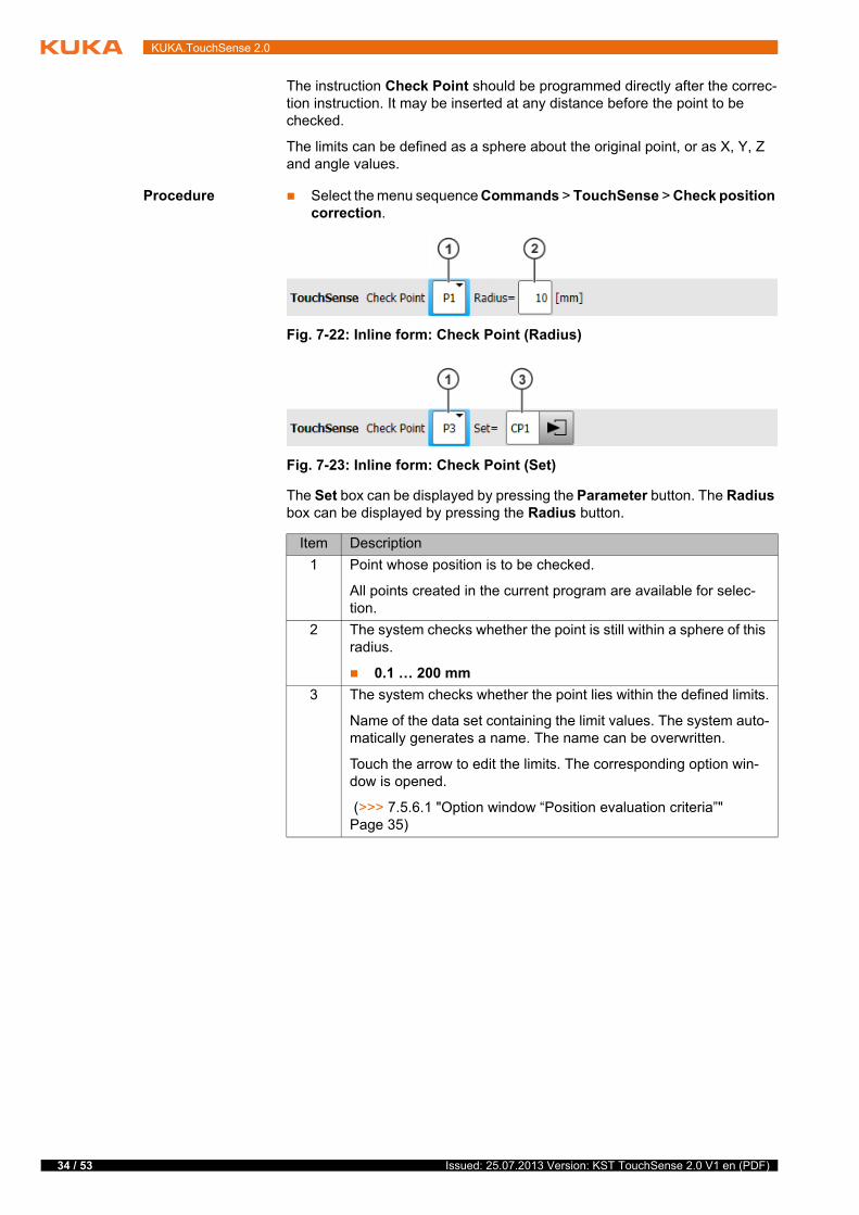
The instruction Check Point should be programmed directly after the correc-tion instruction. It may be inserted at any distance before the point to be checked.
The limits can be defined as a sphere about the original point, or as X, Y, Z and angle values.
Procedure Select the menu sequence Commands > TouchSense > Check position correction.
The Set box can be displayed by pressing the Parameter button. The Radius box can be displayed by pressing the Radius button.
Fig. 7-22: Inline form: Check Point (Radius)
Fig. 7-23: Inline form: Check Point (Set)
Item Description
1 Point whose position is to be checked.
All points created in the current program are available for selec-tion.
2 The system checks whether the point is still within a sphere of this radius.
0.1 … 200 mm
3 The system checks whether the point lies within the defined limits.
Name of the data set containing the limit values. The system auto-matically generates a name. The name can be overwritten.
Touch the arrow to edit the limits. The corresponding option win-dow is opened.
(>>> 7.5.6.1 "Option window “Position evaluation criteria”" Page 35)
Issued: 25.07.2013 Version: KST TouchSense 2.0 V1 en (PDF)

7 Programming
7.5.6.1 Option window “Position evaluation criteria”
Fig. 7-24: Option window: Position evaluation criteria
Item Description
1 Permitted deviation in the X values
2 Permitted deviation in the Y values
3 Permitted deviation in the Z values
4 Permitted deviation in the angle values
35 / 53Issued: 25.07.2013 Version: KST TouchSense 2.0 V1 en (PDF)

36 / 53
KUKA.TouchSense 2.0
Issued: 25.07.2013 Version: KST TouchSense 2.0 V1 en (PDF)
8 Example programs
8 Example programs
8.1 Example program with 3-dimensional correction
Program
Description
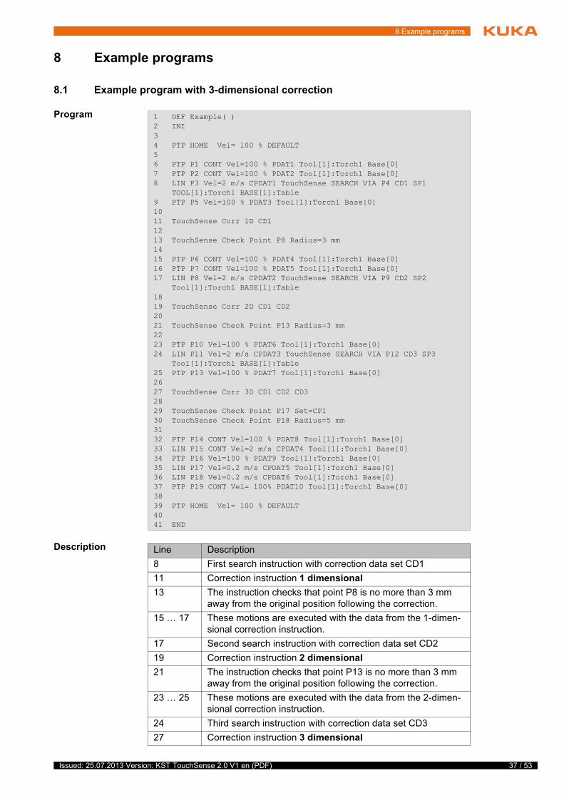
1 DEF Example( )2 INI34 PTP HOME Vel= 100 % DEFAULT56 PTP P1 CONT Vel=100 % PDAT1 Tool[1]:Torch1 Base[0]7 PTP P2 CONT Vel=100 % PDAT2 Tool[1]:Torch1 Base[0]8 LIN P3 Vel=2 m/s CPDAT1 TouchSense SEARCH VIA P4 CD1 SP1 TOOL[1]:Torch1 BASE[1]:Table9 PTP P5 Vel=100 % PDAT3 Tool[1]:Torch1 Base[0]1011 TouchSense Corr 1D CD11213 TouchSense Check Point P8 Radius=3 mm1415 PTP P6 CONT Vel=100 % PDAT4 Tool[1]:Torch1 Base[0]16 PTP P7 CONT Vel=100 % PDAT5 Tool[1]:Torch1 Base[0]17 LIN P8 Vel=2 m/s CPDAT2 TouchSense SEARCH VIA P9 CD2 SP2 Tool[1]:Torch1 BASE[1]:Table1819 TouchSense Corr 2D CD1 CD22021 TouchSense Check Point P13 Radius=3 mm2223 PTP P10 Vel=100 % PDAT6 Tool[1]:Torch1 Base[0]24 LIN P11 Vel=2 m/s CPDAT3 TouchSense SEARCH VIA P12 CD3 SP3 Tool[1]:Torch1 BASE[1]:Table25 PTP P13 Vel=100 % PDAT7 Tool[1]:Torch1 Base[0]2627 TouchSense Corr 3D CD1 CD2 CD32829 TouchSense Check Point P17 Set=CP130 TouchSense Check Point P18 Radius=5 mm3132 PTP P14 CONT Vel=100 % PDAT8 Tool[1]:Torch1 Base[0]33 LIN P15 CONT Vel=2 m/s CPDAT4 Tool[1]:Torch1 Base[0]34 PTP P16 Vel=100 % PDAT9 Tool[1]:Torch1 Base[0]35 LIN P17 Vel=0.2 m/s CPDAT5 Tool[1]:Torch1 Base[0]36 LIN P18 Vel=0.2 m/s CPDAT6 Tool[1]:Torch1 Base[0]37 PTP P19 CONT Vel= 100% PDAT10 Tool[1]:Torch1 Base[0]3839 PTP HOME Vel= 100 % DEFAULT4041 END
Line Description
8 First search instruction with correction data set CD1
11 Correction instruction 1 dimensional
13 The instruction checks that point P8 is no more than 3 mm away from the original position following the correction.
15 … 17 These motions are executed with the data from the 1-dimen-sional correction instruction.
17 Second search instruction with correction data set CD2
19 Correction instruction 2 dimensional
21 The instruction checks that point P13 is no more than 3 mm away from the original position following the correction.
23 … 25 These motions are executed with the data from the 2-dimen-sional correction instruction.
24 Third search instruction with correction data set CD3
27 Correction instruction 3 dimensional
37 / 53Issued: 25.07.2013 Version: KST TouchSense 2.0 V1 en (PDF)
38 / 53
KUKA.TouchSense 2.0
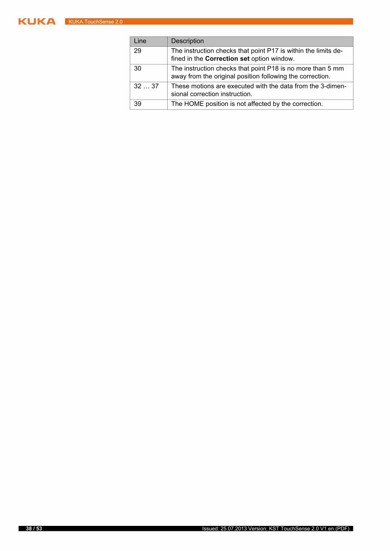
29 The instruction checks that point P17 is within the limits de-fined in the Correction set option window.
30 The instruction checks that point P18 is no more than 5 mm away from the original position following the correction.
32 … 37 These motions are executed with the data from the 3-dimen-sional correction instruction.
39 The HOME position is not affected by the correction.
Line Description
Issued: 25.07.2013 Version: KST TouchSense 2.0 V1 en (PDF)
9 Messages
9 Messages
9.1 Error messages
No. Message Description
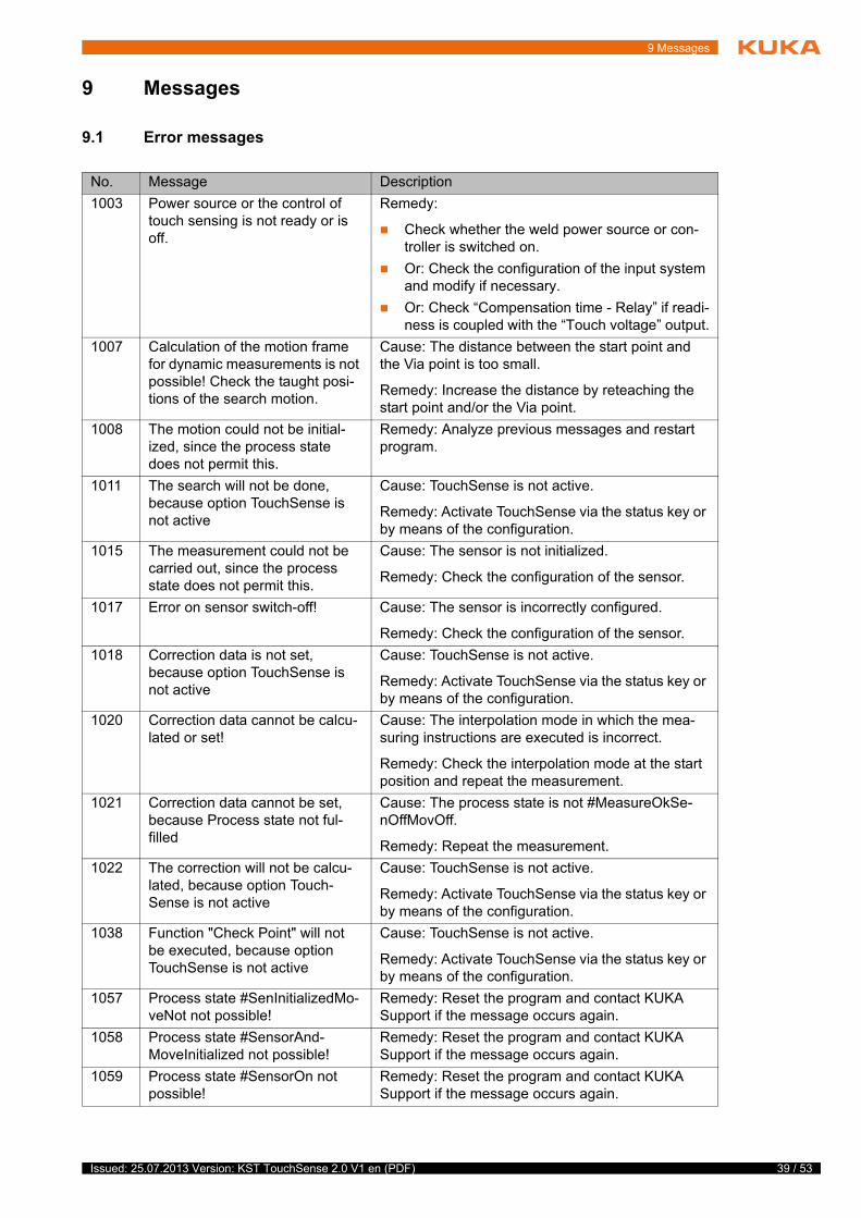
1003 Power source or the control of touch sensing is not ready or is off.
Remedy:
Check whether the weld power source or con-troller is switched on.
Or: Check the configuration of the input system and modify if necessary.
Or: Check “Compensation time - Relay” if readi-ness is coupled with the “Touch voltage” output.
1007 Calculation of the motion frame for dynamic measurements is not possible! Check the taught posi-tions of the search motion.
Cause: The distance between the start point and the Via point is too small.
Remedy: Increase the distance by reteaching the start point and/or the Via point.
1008 The motion could not be initial-ized, since the process state does not permit this.
Remedy: Analyze previous messages and restart program.
1011 The search will not be done, because option TouchSense is not active
Cause: TouchSense is not active.
Remedy: Activate TouchSense via the status key or by means of the configuration.
1015 The measurement could not be carried out, since the process state does not permit this.
Cause: The sensor is not initialized.
Remedy: Check the configuration of the sensor.
1017 Error on sensor switch-off! Cause: The sensor is incorrectly configured.
Remedy: Check the configuration of the sensor.
1018 Correction data is not set, because option TouchSense is not active
Cause: TouchSense is not active.
Remedy: Activate TouchSense via the status key or by means of the configuration.
1020 Correction data cannot be calcu-lated or set!
Cause: The interpolation mode in which the mea-suring instructions are executed is incorrect.
Remedy: Check the interpolation mode at the start position and repeat the measurement.
1021 Correction data cannot be set, because Process state not ful-filled
Cause: The process state is not #MeasureOkSe-nOffMovOff.
Remedy: Repeat the measurement.
1022 The correction will not be calcu-lated, because option Touch-Sense is not active
Cause: TouchSense is not active.
Remedy: Activate TouchSense via the status key or by means of the configuration.
1038 Function "Check Point" will not be executed, because option TouchSense is not active
Cause: TouchSense is not active.
Remedy: Activate TouchSense via the status key or by means of the configuration.
1057 Process state #SenInitializedMo-veNot not possible!
Remedy: Reset the program and contact KUKA Support if the message occurs again.
1058 Process state #SensorAnd-MoveInitialized not possible!
Remedy: Reset the program and contact KUKA Support if the message occurs again.
1059 Process state #SensorOn not possible!
Remedy: Reset the program and contact KUKA Support if the message occurs again.
39 / 53Issued: 25.07.2013 Version: KST TouchSense 2.0 V1 en (PDF)
40 / 53
KUKA.TouchSense 2.0
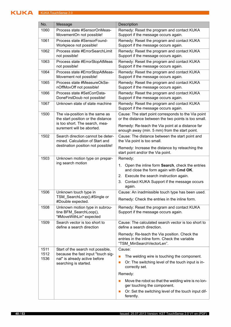
1060 Process state #SensorOnMeas-MovementOn not possible!
Remedy: Reset the program and contact KUKA Support if the message occurs again.
1061 Process state #SensorFound-Workpiece not possible!
Remedy: Reset the program and contact KUKA Support if the message occurs again.
1062 Process state #ErrorSearchLimit not possible!
Remedy: Reset the program and contact KUKA Support if the message occurs again.
1063 Process state #ErrorStopAtMeas not possible!
Remedy: Reset the program and contact KUKA Support if the message occurs again.
1064 Process state #ErrorStopAtMeas-Movement not possible!
Remedy: Reset the program and contact KUKA Support if the message occurs again.
1065 Process state #MeasureOkSe-nOffMovOff not possible!
Remedy: Reset the program and contact KUKA Support if the message occurs again.
1066 Process state #SetCorrData-DoneFirstDoub not possible!
Remedy: Reset the program and contact KUKA Support if the message occurs again.
1067 Unknown state of state machine Remedy: Reset the program and contact KUKA Support if the message occurs again.
1500 The via-position is the same as the start position or the distance is too short. The search, mea-surement will be aborted.
Cause: The start point corresponds to the Via point or the distance between the two points is too small.
Remedy: Re-teach the Via point at a distance far enough away (min. 5 mm) from the start point.
1502 Search direction cannot be deter-mined. Calculation of Start and destination position not possible!
Cause: The distance between the start point and the Via point is too small.
Remedy: Increase the distance by reteaching the start point and/or the Via point.
1503 Unknown motion type on prepar-ing search motion
Remedy:
1. Open the inline form Search, check the entries and close the form again with Cmd OK.
2. Execute the search instruction again.
3. Contact KUKA Support if the message occurs again.
1506 Unknown touch type in TSM_SearchLoop().#Single or #Double expected.
Cause: An inadmissible touch type has been used.
Remedy: Check the entries in the inline form.
1508 Unknown motion type in subrou-tine BFM_SearchLoop(), "#MoveWithLin" expected
Remedy: Reset the program and contact KUKA Support if the message occurs again.
1509 Search vector is too short to define a search direction
Cause: The calculated search vector is too short to define a search direction.
Remedy: Re-teach the Via position. Check the entries in the inline form. Check the variable “TSM_MinSearchVectorLen”.
151115121536
Start of the search not possible, because the fast input "touch sig-nal" is already active before searching is started.
Cause:
The welding wire is touching the component.
Or: The switching level of the touch input is in-correctly set.
Remedy:
Move the robot so that the welding wire is no lon-ger touching the component.
Or: Set the switching level of the touch input dif-ferently.
No. Message Description
Issued: 25.07.2013 Version: KST TouchSense 2.0 V1 en (PDF)

9 Messages
151415151537
Start of the search not possible, because the standard input "touch signal" is already active before searching is started.
Cause:
The welding wire is touching the component.
Or: The switching level of the touch input is in-correctly set.
Remedy:
Move the robot so that the welding wire is no lon-ger touching the component.
Or: Set the switching level of the touch input dif-ferently.
1519 Unknown touch type in TSM_SearchLoopCP(). "#Sin-gle", "#FirstDouble" oder "#Sec-ondDouble" expected.
Cause: An inadmissible touch type has been used.
Remedy: Check the entries in the inline form.
1526 Calculated target position reached but workpiece not recog-nized
Cause: The complete search distance was covered without the workpiece being detected. Many possi-ble reasons, including: The workpiece is located outside the search window of the sensor. Or fouling in the field of view of the sensor.
Remedy: Depends on the reason, for example: Reprogram the search with a longer search path.
2000 The selected sensor is Null Cause: There is no valid sensor selected.
Remedy: Check the selection of the sensor in the inline form and the configuration of the sensor.
2001 The selected sensor is not con-figured
Cause: A sensor that is not configured has been selected in the inline form.
Remedy: Either configure the selected sensor or select a configured sensor in the inline form.
2002 Input for "Touch signal" exceeds the system input range.
Cause: The value for the touch signal input is greater than the number of inputs.
Remedy: Enter a value for the touch signal input that is lower than the number of inputs.
2500 No correction is calculated. Indi-vidual data sets are incorrectly preset.
Cause: For some CDx either no measurement or no successful measurement has been performed.
Remedy: Repeat all the measurements.
2501 No correction calculated. Correc-tion data set type mismatch.
Cause: The CDx originate from measuring instruc-tions that are executed partly with interpolation mode = TRUE and partly with FALSE. This mixture is not permissible.
Remedy: Execute all measuring instructions in the same mode. (The interpolation mode is defined in the Frames option window.)
No. Message Description
41 / 53Issued: 25.07.2013 Version: KST TouchSense 2.0 V1 en (PDF)
42 / 53
KUKA.TouchSense 2.0
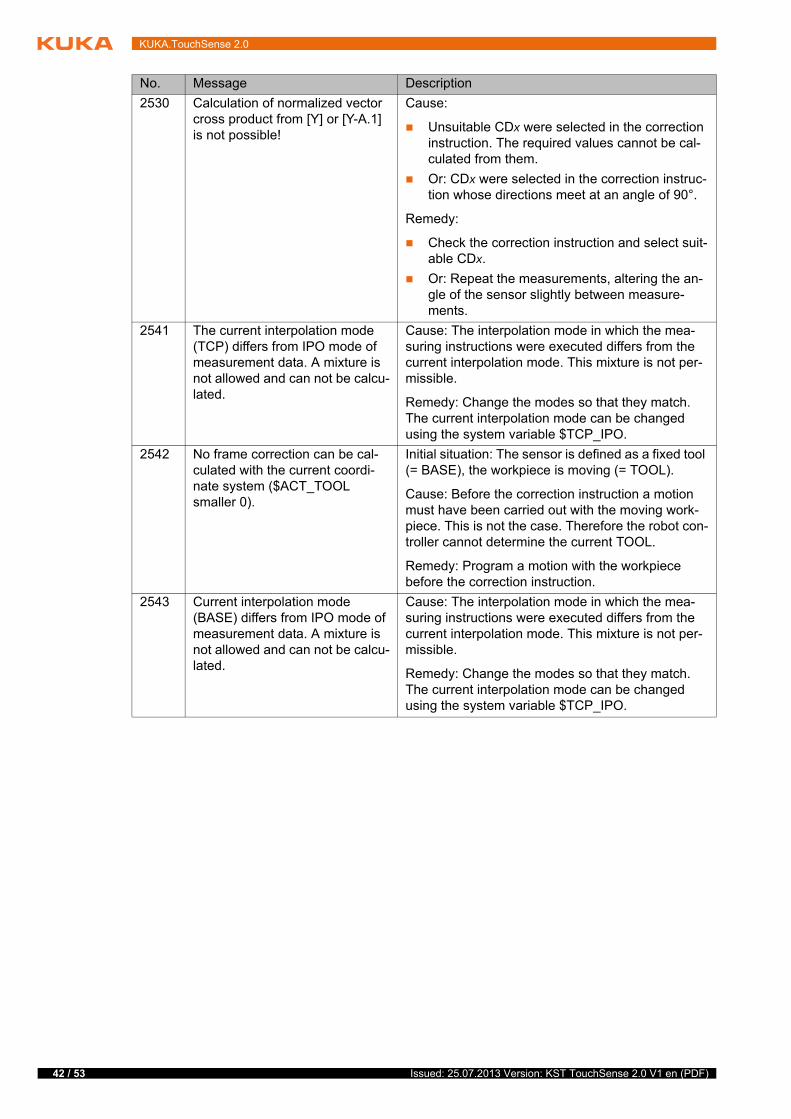
2530 Calculation of normalized vector cross product from [Y] or [Y-A.1] is not possible!
Cause:
Unsuitable CDx were selected in the correction instruction. The required values cannot be cal-culated from them.
Or: CDx were selected in the correction instruc-tion whose directions meet at an angle of 90°.
Remedy:
Check the correction instruction and select suit-able CDx.
Or: Repeat the measurements, altering the an-gle of the sensor slightly between measure-ments.
2541 The current interpolation mode (TCP) differs from IPO mode of measurement data. A mixture is not allowed and can not be calcu-lated.
Cause: The interpolation mode in which the mea-suring instructions were executed differs from the current interpolation mode. This mixture is not per-missible.
Remedy: Change the modes so that they match. The current interpolation mode can be changed using the system variable $TCP_IPO.
2542 No frame correction can be cal-culated with the current coordi-nate system ($ACT_TOOL smaller 0).
Initial situation: The sensor is defined as a fixed tool (= BASE), the workpiece is moving (= TOOL).
Cause: Before the correction instruction a motion must have been carried out with the moving work-piece. This is not the case. Therefore the robot con-troller cannot determine the current TOOL.
Remedy: Program a motion with the workpiece before the correction instruction.
2543 Current interpolation mode (BASE) differs from IPO mode of measurement data. A mixture is not allowed and can not be calcu-lated.
Cause: The interpolation mode in which the mea-suring instructions were executed differs from the current interpolation mode. This mixture is not per-missible.
Remedy: Change the modes so that they match. The current interpolation mode can be changed using the system variable $TCP_IPO.
No. Message Description
Issued: 25.07.2013 Version: KST TouchSense 2.0 V1 en (PDF)
10 KUKA Service
10 KUKA Service
10.1 Requesting support
Introduction The KUKA Roboter GmbH documentation offers information on operation and provides assistance with troubleshooting. For further assistance, please con-tact your local KUKA subsidiary.
Information The following information is required for processing a support request:
Model and serial number of the manipulator
Model and serial number of the controller
Model and serial number of the linear unit (if applicable)
Model and serial number of the energy supply system (if applicable)
Version of the KUKA System Software
Optional software or modifications
Archive of the software
Application used
Any external axes used (if applicable)
Description of the problem, duration and frequency of the fault
10.2 KUKA Customer Support
Availability KUKA Customer Support is available in many countries. Please do not hesi-tate to contact us if you have any questions.
Argentina Ruben Costantini S.A. (Agency)
Luis Angel Huergo 13 20
Parque Industrial
2400 San Francisco (CBA)
Argentina
Tel. +54 3564 421033
Fax +54 3564 428877
Australia Headland Machinery Pty. Ltd.
Victoria (Head Office & Showroom)
95 Highbury Road
Burwood
Victoria 31 25
Australia
Tel. +61 3 9244-3500
Fax +61 3 9244-3501
www.headland.com.au
43 / 53Issued: 25.07.2013 Version: KST TouchSense 2.0 V1 en (PDF)
44 / 53
KUKA.TouchSense 2.0
Belgium KUKA Automatisering + Robots N.V.
Centrum Zuid 1031
3530 Houthalen
Belgium
Tel. +32 11 516160
Fax +32 11 526794
www.kuka.be
Brazil KUKA Roboter do Brasil Ltda.
Travessa Claudio Armando, nº 171
Bloco 5 - Galpões 51/52
Bairro Assunção
CEP 09861-7630 São Bernardo do Campo - SP
Brazil
Tel. +55 11 4942-8299
Fax +55 11 2201-7883
www.kuka-roboter.com.br
Chile Robotec S.A. (Agency)
Santiago de Chile
Chile
Tel. +56 2 331-5951
Fax +56 2 331-5952
www.robotec.cl
China KUKA Robotics China Co.,Ltd.
Songjiang Industrial Zone
No. 388 Minshen Road
201612 Shanghai
China
Tel. +86 21 6787-1888
Fax +86 21 6787-1803
www.kuka-robotics.cn
Germany KUKA Roboter GmbH
Zugspitzstr. 140
86165 Augsburg
Germany
Tel. +49 821 797-4000
Fax +49 821 797-1616
www.kuka-roboter.de
Issued: 25.07.2013 Version: KST TouchSense 2.0 V1 en (PDF)
10 KUKA Service
France KUKA Automatisme + Robotique SAS
Techvallée
6, Avenue du Parc
91140 Villebon S/Yvette
France
Tel. +33 1 6931660-0
Fax +33 1 6931660-1
www.kuka.fr
India KUKA Robotics India Pvt. Ltd.
Office Number-7, German Centre,
Level 12, Building No. - 9B
DLF Cyber City Phase III
122 002 Gurgaon
Haryana
India
Tel. +91 124 4635774
Fax +91 124 4635773
www.kuka.in
Italy KUKA Roboter Italia S.p.A.
Via Pavia 9/a - int.6
10098 Rivoli (TO)
Italy
Tel. +39 011 959-5013
Fax +39 011 959-5141
www.kuka.it
Japan KUKA Robotics Japan K.K.
YBP Technical Center
134 Godo-cho, Hodogaya-ku
Yokohama, Kanagawa
240 0005
Japan
Tel. +81 45 744 7691
Fax +81 45 744 7696
Canada KUKA Robotics Canada Ltd.
6710 Maritz Drive - Unit 4
Mississauga
L5W 0A1
Ontario
Canada
Tel. +1 905 670-8600
Fax +1 905 670-8604
www.kuka-robotics.com/canada
45 / 53Issued: 25.07.2013 Version: KST TouchSense 2.0 V1 en (PDF)
46 / 53
KUKA.TouchSense 2.0
Korea KUKA Robotics Korea Co. Ltd.
RIT Center 306, Gyeonggi Technopark
1271-11 Sa 3-dong, Sangnok-gu
Ansan City, Gyeonggi Do
426-901
Korea
Tel. +82 31 501-1451
Fax +82 31 501-1461
Malaysia KUKA Robot Automation Sdn Bhd
South East Asia Regional Office
No. 24, Jalan TPP 1/10
Taman Industri Puchong
47100 Puchong
Selangor
Malaysia
Tel. +60 3 8061-0613 or -0614
Fax +60 3 8061-7386
Mexico KUKA de México S. de R.L. de C.V.
Progreso #8
Col. Centro Industrial Puente de Vigas
Tlalnepantla de Baz
54020 Estado de México
Mexico
Tel. +52 55 5203-8407
Fax +52 55 5203-8148
www.kuka-robotics.com/mexico
Norway KUKA Sveiseanlegg + Roboter
Sentrumsvegen 5
2867 Hov
Norway
Tel. +47 61 18 91 30
Fax +47 61 18 62 00
Austria KUKA Roboter Austria GmbH
Vertriebsbüro Österreich
Regensburger Strasse 9/1
4020 Linz
Austria
Tel. +43 732 784752
Fax +43 732 793880
www.kuka-roboter.at
Issued: 25.07.2013 Version: KST TouchSense 2.0 V1 en (PDF)
10 KUKA Service
Poland KUKA Roboter Austria GmbH
Spółka z ograniczoną odpowiedzialnością
Oddział w Polsce
Ul. Porcelanowa 10
40-246 Katowice
Poland
Tel. +48 327 30 32 13 or -14
Fax +48 327 30 32 26
Portugal KUKA Sistemas de Automatización S.A.
Rua do Alto da Guerra n° 50
Armazém 04
2910 011 Setúbal
Portugal
Tel. +351 265 729780
Fax +351 265 729782
Russia OOO KUKA Robotics Rus
Webnaja ul. 8A
107143 Moskau
Russia
Tel. +7 495 781-31-20
Fax +7 495 781-31-19
kuka-robotics.ru
Sweden KUKA Svetsanläggningar + Robotar AB
A. Odhners gata 15
421 30 Västra Frölunda
Sweden
Tel. +46 31 7266-200
Fax +46 31 7266-201
Switzerland KUKA Roboter Schweiz AG
Industriestr. 9
5432 Neuenhof
Switzerland
Tel. +41 44 74490-90
Fax +41 44 74490-91
www.kuka-roboter.ch
47 / 53Issued: 25.07.2013 Version: KST TouchSense 2.0 V1 en (PDF)

48 / 53
KUKA.TouchSense 2.0
Spain KUKA Robots IBÉRICA, S.A.
Pol. Industrial
Torrent de la Pastera
Carrer del Bages s/n
08800 Vilanova i la Geltrú (Barcelona)
Spain
Tel. +34 93 8142-353
Fax +34 93 8142-950
www.kuka-e.com
South Africa Jendamark Automation LTD (Agency)
76a York Road
North End
6000 Port Elizabeth
South Africa
Tel. +27 41 391 4700
Fax +27 41 373 3869
www.jendamark.co.za
Taiwan KUKA Robot Automation Taiwan Co., Ltd.
No. 249 Pujong Road
Jungli City, Taoyuan County 320
Taiwan, R. O. C.
Tel. +886 3 4331988
Fax +886 3 4331948
www.kuka.com.tw
Thailand KUKA Robot Automation (M)SdnBhd
Thailand Office
c/o Maccall System Co. Ltd.
49/9-10 Soi Kingkaew 30 Kingkaew Road
Tt. Rachatheva, A. Bangpli
Samutprakarn
10540 Thailand
Tel. +66 2 7502737
Fax +66 2 6612355
www.kuka-roboter.de
Czech Republic KUKA Roboter Austria GmbH
Organisation Tschechien und Slowakei
Sezemická 2757/2
193 00 Praha
Horní Počernice
Czech Republic
Tel. +420 22 62 12 27 2
Fax +420 22 62 12 27 0
Issued: 25.07.2013 Version: KST TouchSense 2.0 V1 en (PDF)
10 KUKA Service
Hungary KUKA Robotics Hungaria Kft.
Fö út 140
2335 Taksony
Hungary
Tel. +36 24 501609
Fax +36 24 477031
USA KUKA Robotics Corporation
51870 Shelby Parkway
Shelby Township
48315-1787
Michigan
USA
Tel. +1 866 873-5852
Fax +1 866 329-5852
www.kukarobotics.com
UK KUKA Automation + Robotics
Hereward Rise
Halesowen
B62 8AN
UK
Tel. +44 121 585-0800
Fax +44 121 585-0900
49 / 53Issued: 25.07.2013 Version: KST TouchSense 2.0 V1 en (PDF)

50 / 53
KUKA.TouchSense 2.0
Issued: 25.07.2013 Version: KST TouchSense 2.0 V1 en (PDF)
Index
Index
CCheck Point (inline form) 33Communication 7Configuration 17Corr Off (inline form) 33Correction, 1D (inline form) 27Correction, 2D (inline form) 28Correction, 3D (inline form) 29Correction, freely programmable (inline form) 30Correction, programming 27
DDocumentation, industrial robot 5Double Touch 8
EError messages 39Example programs 37
FFast Measurement 6Fixed sensor 21Functional principle 7
GGeneral settings (tab) 17
IInstallation 13Installing TouchSense 13Introduction 5
KKUKA Customer Support 43
MMenus 15Messages 39
OOperation 15Overview, KUKA.TouchSense 7
PParameters, setting 20Product description 7Programming 21Programming, correction 27Programming, instructions 21
SSafety 11Safety instructions 5Search (inline form) 21Search dynamic (tab) 18Sensor configuration, tab 19Sensor, fixed 21Service, KUKA Roboter 43
Single Touch 8Single-V butt weld 6Square butt weld 6Status keys 15Support request 43System requirements 13
TTerms used 6TouchSense, configuring (HMI) 17TouchSense, configuring (WorkVisual) 19Training 5
UUninstalling TouchSense 14Updating TouchSense 13
VVia point 23
WWarnings 5
51 / 53Issued: 25.07.2013 Version: KST TouchSense 2.0 V1 en (PDF)

52 / 53
KUKA.TouchSense 2.0
Issued: 25.07.2013 Version: KST TouchSense 2.0 V1 en (PDF)

53 / 53Issued: 25.07.2013 Version: KST TouchSense 2.0 V1 en (PDF)
KUKA.TouchSense 2.0