kualitas dayakualitas daya (power quality) · pdf filethe power quality community has used the...
TRANSCRIPT

KUALITAS DAYAKUALITAS DAYA(POWER QUALITY)
ASNILELEKTRO FT - UNP
Definition of power Quality terms
Th t lit i li d t id i t fThe term power quality is applied to a wide variety of electromagnetic phenomena on the power system. The increasing application of electronic equipment andincreasing application of electronic equipment and distributed generation has heightened the interest in power quality in recent years, and this has been accompanied by q y y p ythe development of a special terminology to describe the phenomena.
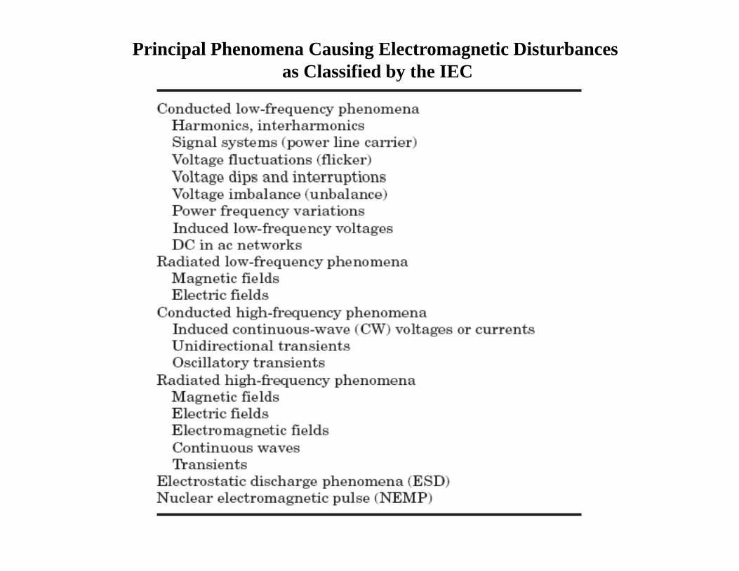
Principal Phenomena Causing Electromagnetic Disturbancesas Classified by the IEC

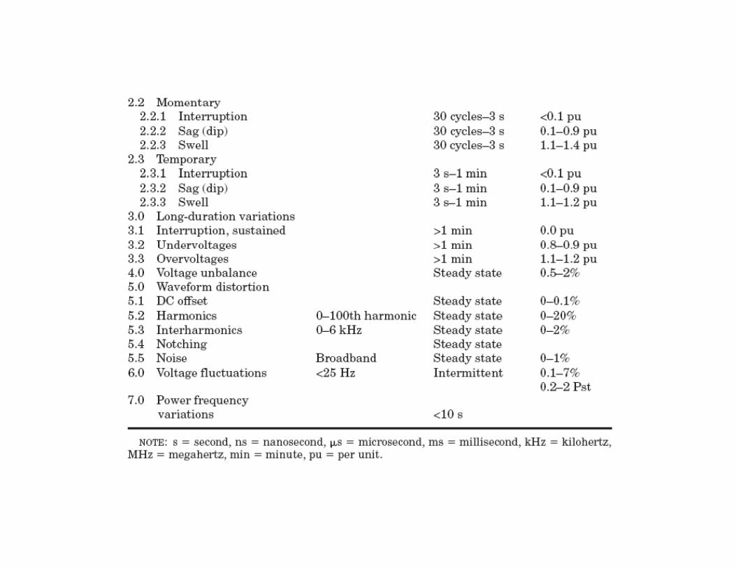
Categories and Characteristics of Power System Electromagnetic Phenomenay g

Transients
A transient is an undesirable momentary deviation of the supply voltage or load current.
Broadly speaking, transients can be classified into two categories, impulsive and oscillatory.g , p y
An impulsive transient is an abrupt change in the steady t t lt d/ t th t t id thstate voltage and/or current, that occurs outside the
power frequency range and is unidirectional in polarity.
A i l i i i ddAn impulsive transient is a sudden, non–power frequency steady-state condition of voltage, current, or both that in polarity (primarily either positive oror both that in polarity (primarily either positive or negative).

Figure Lightning stroke current impulsive transient.
Figure Waveform showing an impulsive transient event
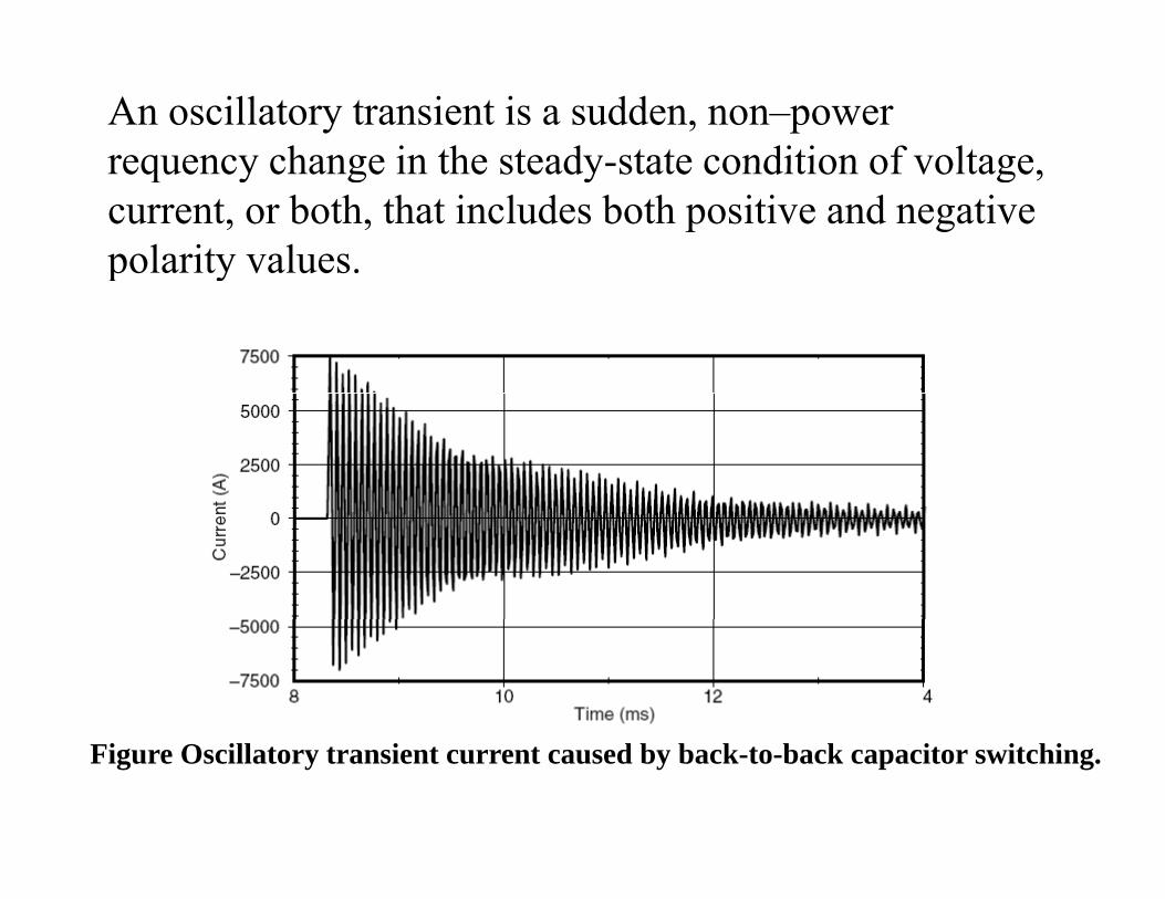
An oscillatory transient is a sudden, non–power requency change in the steady-state condition of voltagerequency change in the steady state condition of voltage, current, or both, that includes both positive and negative polarity values.p y
Figure Oscillatory transient current caused by back-to-back capacitor switching.
Short-Duration Voltage Variations
This category encompasses the IEC category of voltage dips and short interruptions Each type of variation can bedips and short interruptions. Each type of variation can be designated as instantaneous, momentary, or temporary, depending on its durationdepending on its duration
Short-duration voltage variations are caused by fault conditions, the energization of large loads which require high starting currents, or intermittent loose connections in
i i D di th f lt l ti d thpower wiring. Depending on the fault location and the system conditions, the fault can cause either temporary voltage drops (sags) voltage rises (swells) or a completevoltage drops (sags), voltage rises (swells), or a complete loss of voltage (interruptions).

A h h l l l d
InterruptionAn interruption occurs when the supply voltage or load currentdecreases to less than 0.1 pu for a period of time not exceeding 1 min.
Interruptions can be the result of power system faults, equipmentf il d t l lf ti Th i t ti dfailures, and control malfunctions. The interruptions are measured by their duration since the voltage magnitude is always less than 10 percent of nominal. The duration of an interruption due to a fault on the utility system is determined by the operating time of utility protective devices.
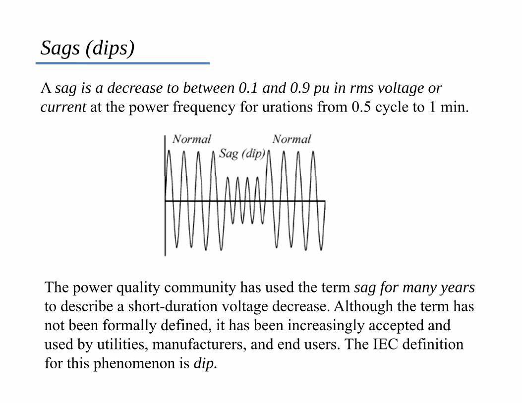
Sags (dips)
A sag is a decrease to between 0.1 and 0.9 pu in rms voltage or current at the power frequency for urations from 0.5 cycle to 1 min.
The power quality community has used the term sag for many yearsto describe a short-duration voltage decrease. Although the term has not been formally defined, it has been increasingly accepted andnot been formally defined, it has been increasingly accepted and used by utilities, manufacturers, and end users. The IEC definition for this phenomenon is dip.
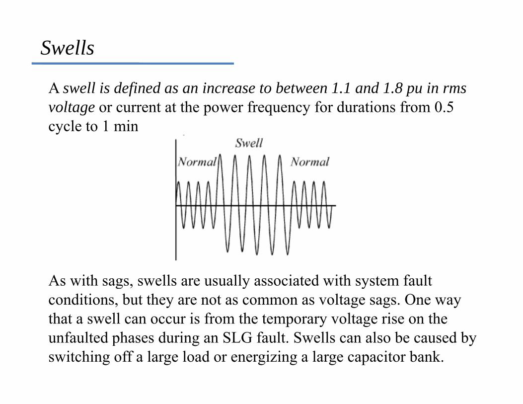
Swells
A swell is defined as an increase to between 1.1 and 1.8 pu in rmsvoltage or current at the power frequency for durations from 0.5 cycle to 1 mincycle to 1 min
As with sags swells are usually associated with system faultAs with sags, swells are usually associated with system fault conditions, but they are not as common as voltage sags. One way that a swell can occur is from the temporary voltage rise on the unfaulted phases during an SLG fault. Swells can also be caused by switching off a large load or energizing a large capacitor bank.

Figure Three-phase rmsvoltages for a momentary interruption due to a faultand subsequent recloser
ioperation.
Figure Instantaneous gvoltage swell caused by an SLG fault.
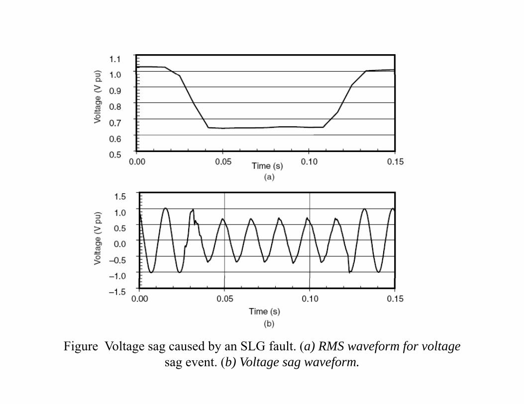
Figure Voltage sag caused by an SLG fault. (a) RMS waveform for voltagesag event. (b) Voltage sag waveform.
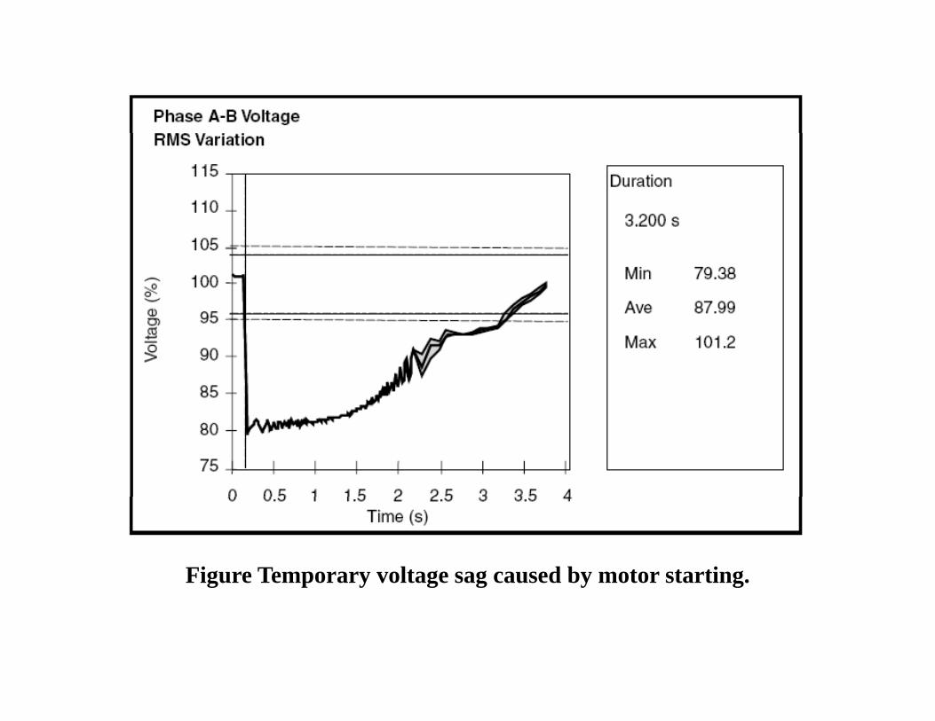
Figure Temporary voltage sag caused by motor starting.
Long-Duration Voltage Variations
Long-duration variations can be either overvoltages or ndervoltages.Overvoltages and undervoltages generally are not the result ofsystem faults, but are caused by load variations on the system and system switching operations.
Overvoltage
An overvoltage is an increase in the rms ac voltage greater than percent at the power frequency for a duration longer than 1 min.
Overvoltages are usually the result of load switching (e.g., switching off a large load or energizing a capacitor bank).

UndervoltageAn undervoltage is a decrease in the rms ac voltage to less than 90 percent at the power frequency for a duration longer than 1 min.
Undervoltages are the result of switching events that are the opposite of the events that cause overvoltages. A load switching on or a capacitor bank switching off can cause an undervoltage until p g gvoltage regulation equipment on the system can bring the voltageback to within tolerances. Overloaded circuits can result in undervoltages alsoundervoltages also.
Sustained interruptionsWhen the supply voltage has been zero for a period of time in excess of 1 min, the long-duration voltage variation is considered a sustained interruption Voltage interruptions longer than 1 min aresustained interruption. Voltage interruptions longer than 1 min are often permanent and require human intervention to repair the system for restoration.

Voltage Imbalance
Voltage imbalance (also called voltage unbalance) is sometimes defined as the maximum deviation from the average of the three-h lt t di id d b th f th th hphase voltages or currents, divided by the average of the three-phase
voltages or currents, expressed in percent.Unbalance describes a situation in which either the voltages of aUnbalance describes a situation, in which either the voltages of a three-phase voltage source are not identical in magnitude, or the phase differences between them are not 120 electrical degrees, or b thboth . The simplest method of expressing voltage unbalance is to measure the voltage deviationΔu at each of the three phases, and compare itthe voltage deviation Δu at each of the three phases, and compare it to the average phase voltage Ua:
where: Cvu - the voltage unbalance coefficient
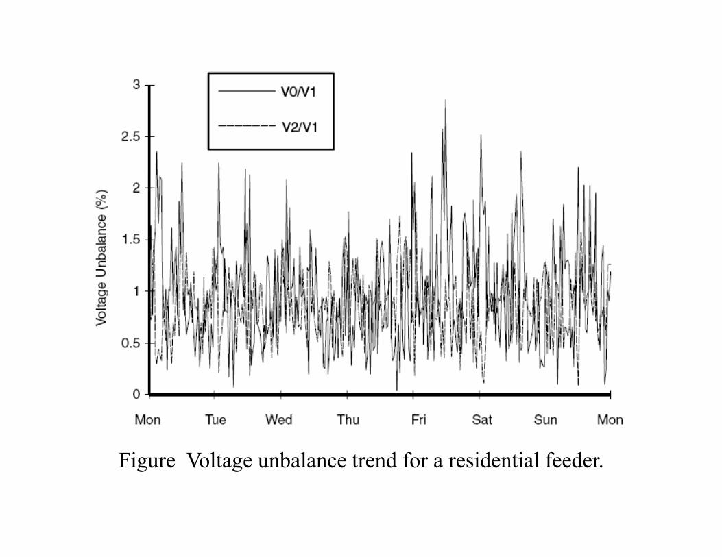
Fi V lt b l t d f id ti l f dFigure Voltage unbalance trend for a residential feeder.
The primary source of voltage unbalances of less than 2 percent is single-phase loads on a three-phase circuit. Voltage unbalance can g p p galso be the result of blown fuses in one phase of a three-phase capacitor bank. Severe voltage unbalance (greater than 5 percent) can result from single-phasing conditionscan result from single-phasing conditions.
Waveform DistortionWaveform DistortionWaveform distortion is defined as a steady-state deviation from an ideal sine wave of power frequency principally characterized by theideal sine wave of power frequency principally characterized by thespectral content of the deviation.There are five primary types of waveform distortion:p y ypDC offsetHarmonics
NotchingNoise
Interharmonics
DC offset.
The presence of a dc voltage or current in an ac power system is termed dc offset. This can occur as the result of a
ti di t b t f l t igeomagnetic disturbance or asymmetry of electronic power converters. Incandescent light bulb life extenders, for example may consist of diodes that reduce the rms voltageexample, may consist of diodes that reduce the rms voltage supplied to the light bulb by half-wave rectification. Direct current in ac networks can have a detrimental effect by biasing transformer cores so they saturate in normal operation. This causes additional heating and loss of
f lif Di l htransformer life. Direct current may also cause the electrolytic erosion of grounding electrodes and other connectorsconnectors.

Harmonics.Harmonics are sinusoidal voltages or currents having frequenciesthat are integer multiples of the frequency at which the supply system i d i d t t (t d th f d l f ll 50is designed to operate (termed the fundamental frequency; usually 50 or 60 Hz).
Gambar Gelombang fundamental Gambar Gelombang fundamental danGambar Gelombang fundamental dan harmonik ke-3 berbeda fasa 1800
Gambar Gelombang fundamental dan harmonik ke-3 berbeda fasa 00
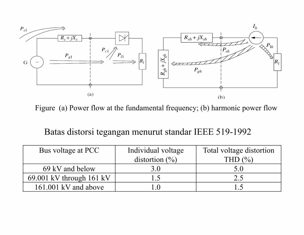
Figure (a) Power flow at the fundamental frequency; (b) harmonic power flow
Batas distorsi tegangan menurut standar IEEE 519-1992
Bus voltage at PCC Individual voltage distortion (%)
Total voltage distortion THD (%)
Batas distorsi tegangan menurut standar IEEE 519-1992
d s o o (%) (%)69 kV and below 3.0 5.0
69.001 kV through 161 kV 1.5 2.5161.001 kV and above 1.0 1.5

Isc/IL <11 11h<17 17h<23 23h<35 h TDD
Batas distorsi arus menurut standar IEEE 519-1992
Isc/IL <11 11h<17 17h<23 23h<35 h TDD<20 4.0 2.0 1.5 0.6 0.3 5.0
20<50 7.0 3.5 2.5 1.0 0.5 8.050<100 10.0 4.5 4.0 1.5 0.7 12.0
100<1000 12.0 5.5 5.0 2.0 1.0 15.0>1000 15.0 7.0 6.0 2.5 1.4 20.0
Di t t d lt t f t i i i di di t ti
Inter-harmonicsDistorted voltage or current waveforms containing periodic distortions ofa sinusoidal nature that are not integer multiples of the fundamental supply frequency are termed inter-harmonics.Interharmonics can be found in networks of all voltage classes. The main sources of interharmonic waveform distortion are static frequency converters cycloconverters induction furnaces and arcingfrequency converters, cycloconverters, induction furnaces, and arcing devices. Power line carrier signals can also be considered as interharmonics.

Notching
Notching is a periodic voltage disturbance caused by the normal operation of power electronic devices when current is commutatedoperation of power electronic devices when current is commutatedfrom one phase to another.
The notches occur when the current commutates from one phase toThe notches occur when the current commutates from one phase to another. During this period, there is a momentary short circuit between two phases, pulling the voltage as close to zero as permitted by system impedances.
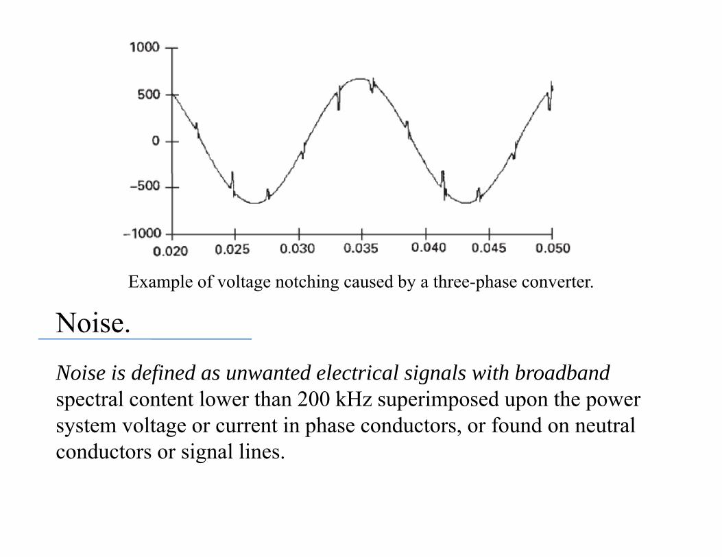
Example of voltage notching caused by a three-phase converter.
N iNoise.Noise is defined as unwanted electrical signals with broadband f gspectral content lower than 200 kHz superimposed upon the power system voltage or current in phase conductors, or found on neutral conductors or signal linesconductors or signal lines.
Noise in power systems can be caused by power electronic devices, control circuits, arcing equipment, loads with solid-state rectifiers,
d i hi li N i bl f b dand switching power supplies. Noise problems are often exacerbated by improper grounding that fails to conduct noise away from the power system. Basically, noise consists of any unwanted distortion p y y yof the power signal that cannot be classified as harmonic distortion or transients. Noise disturbs electronic devices such as microcomputer and programmable controllers The problem can bemicrocomputer and programmable controllers. The problem can be mitigated by using filters, isolation transformers, and line conditioners.
Voltage Fluctuation
Voltage fluctuations are systematic variations of the voltage envelopeor a series of random voltage changes, the magnitude of which does not normally exceed the voltage ranges specified by ANSI C84 1 ofnot normally exceed the voltage ranges specified by ANSI C84.1 of 0.9 to 1.1 pu.
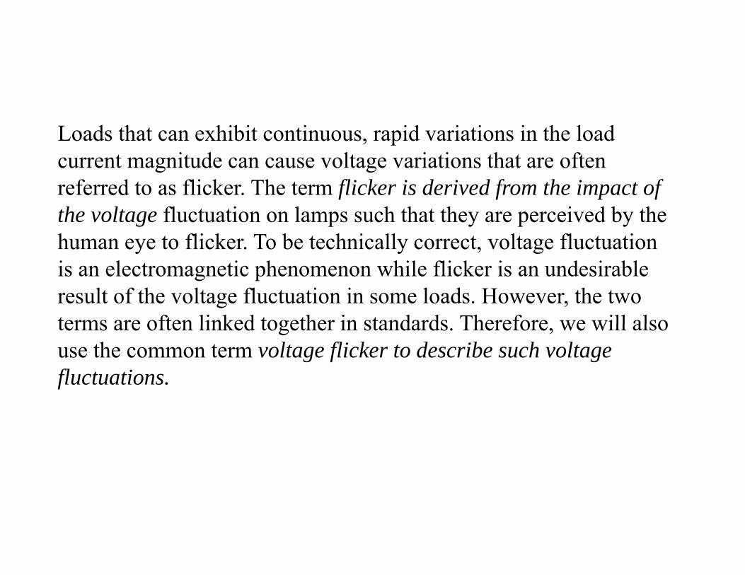
Loads that can exhibit continuous, rapid variations in the load current magnitude can cause voltage variations that are often referred to as flicker. The term flicker is derived from the impact of the voltage fluctuation on lamps such that they are perceived by the human eye to flicker. To be technically correct, voltage fluctuation y y , gis an electromagnetic phenomenon while flicker is an undesirable result of the voltage fluctuation in some loads. However, the two terms are often linked together in standards Therefore we will alsoterms are often linked together in standards. Therefore, we will also use the common term voltage flicker to describe such voltage fluctuations.

Example of voltage fluctuations caused by arc furnace operation.

Power Frequency Variations
Power frequency variations are defined as the deviation of the power system fundamental frequency from it specified nominal
l ( 50 60 H ) A i ti i f f thvalue (e.g., 50 or 60 Hz), or A variation in frequency from the nominal supply frequency above/below a predetermined level normally 0.1%.
Voltage notching can sometimes be mistaken for frequency deviation. The notches may come sufficiently close to zero to cause errors in instruments and control systems that rely on zero crossings to derive frequency or time.
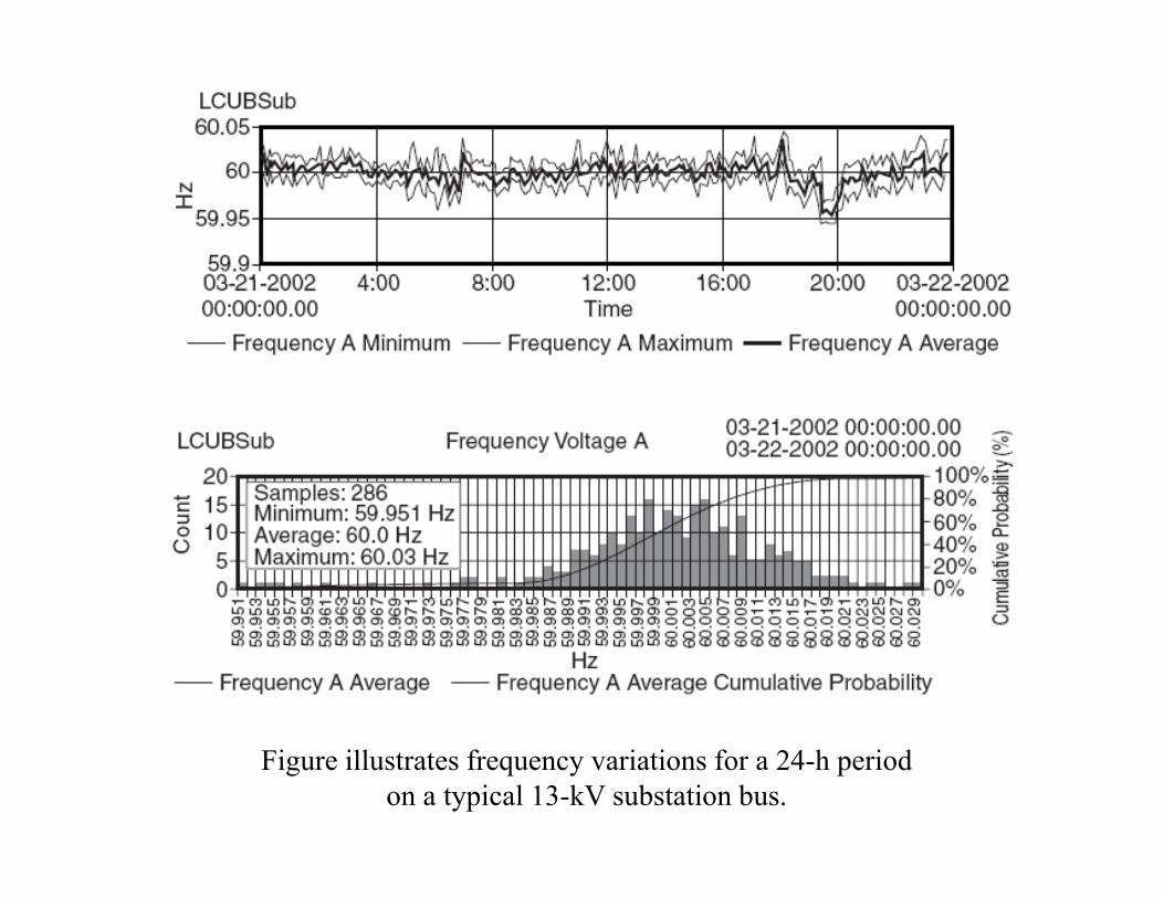
Figure illustrates frequency variations for a 24-h period on a typical 13-kV substation bus.