krisys robot experiential learning in product development...
TRANSCRIPT

1
Proceedings of the 2014 ASEE Gulf-Southwest Conference
Organized by Tulane University, New Orleans, Louisiana
Copyright © 2014, American Society for Engineering Education
KRISYS ROBOT: EXPERIENTIAL LEARNING IN PRODUCT
DEVELOPMENT
Sean Kogucz, Joana Aguirre, Alejandro Alferez, and Joseph Morgan
Electronic Systems Engineering Technology
Texas A&M University
Abstract:
Texas A&M Electronic Systems Engineering Technology (ESET) focuses on innovative product
and systems design and development. To this end, the ESET curriculum includes a Sophomore-
level course in digital logic that provides one of the first opportunities for ESET undergraduate
students to design, build, test, optimize, compete and document an autonomous robot. The final
course project integrates all of the fundamental concepts taught in the course for both
combinatorial and sequential logic circuitry. These logical circuits form the basis for the creation
of the Krisys Robot which is a student-created autonomous robot capable of self-locomotion.
Introduction:
The Electronic Systems Engineering Technology (ESET) Program at Texas A&M University
has, over the past two years, transitioned its curriculum to a product development focus. As part
of this transformation, most ESET courses and their associated laboratories have a course project
that requires individuals or small groups of students to design, develop, test, optimize, deliver
and document a fully functional product or system. This experiential approach to technical
education begins in the sophomore year and carries through to the Capstone Design project. In
the lower level courses, students are provided more guidance in their development processes, but
are still encouraged to be innovative in the design and implementation phases. At the senior
level, students self-select teams which then operate as startup companies. The teams identify and
select a problem statement for an embedded intelligence-based product/system which is usually
generated by a private or public sector customer who then sponsors the project through grant
funding. The teams do solicit an advisor from the ESET faculty, but are responsible for all
aspects of converting the problem statement into a fully functioning prototype.
In ENTC 219, Digital Design, the students learn about hardware implementation of
combinatorial and sequential logic circuitry. They are introduced to the National Instruments
Multisim schematic capture environment for circuit design starting at the fundamental logic gate
level. Using small scale integration technology, students design, implement and test functional
combinatorial devices such as decoders, selectors and comparators. Later in the course they add
sequential logic circuit and state-machine design concepts. Laboratory assignments include
counters and controllers as well as hybrid circuits such as variable Pulse Width Modulation
(PWM) generator circuits. Each laboratory assignment provides insight into the circuitry they

2
Proceedings of the 2014 ASEE Gulf-Southwest Conference
Organized by Tulane University, New Orleans, Louisiana
Copyright © 2014, American Society for Engineering Education
will need in their final course project. These circuits are first simulated, tested and understood
using the word generator and logic analyzer available with Multisim.
Once the circuit has been successfully simulated, students compile and download their circuit
using Xilinx FPGA tools to the Spartan 3E device on the Digilent Basys2 Development Board.
The Basys2 Board is excellent for this type of course based on its low cost and the large number
of I/O available. Using PMods available from Digilent, the board’s capability can be easily
expanded. Each student is issued a Basys2 Board when they enter the ENTC 219 course which
allows them to do most of their laboratory assignments outside of the scheduled lab hours using
the Multisim development environment on their laptops. This approach to digital design allows
the student more flexibility in learning the material and expanding on the designs required for the
course. Circuits designed in class or created in homework assignments and quizzes can be easily
validated with Multisim and the Basys2 Board.
The final course project integrates both digital and analog electronics with the various
mechanical concepts. Each student must purchase a basic parts kit that allows them to design
their own small form factor robot that has the ability to autonomously follow an alternating
current that flows through a thin-gauged wire that is taped to the floor. The Basys2 Board
provides the on-board intelligence that senses the environment and controls all aspects of the
robot using a state machine and auxiliary digital circuits. In addition to this independent
assignment, the students participate in a “Race of Champions” that is sponsored by Xilinx.
Finished designs are shown in Figure 1.
Students form two-person teams where one robot must compete in the Drag Race (long, straight,
and fast) while the other robot must compete in the Road Race (longer, sharp turns, and slower).
Each team gets two attempts at each race, the fastest time is used, and then added together to
form a combined Drag and Road race total time. The team with the fastest overall time is
declared the winner and receives a check for $250 from Xilinx. The second place team receives
$150 and the third place team receives $100.
This paper describes the laboratory assignments and the course project in detail. In addition, all
aspects of the final autonomous robot design; implementation, testing, and optimization are
provided. Lessons learned and recommendations are also provided. The intent is that the paper
can be used by other educational undergraduate programs interested in implementing a similar
experiential learning opportunity within their first digital design course.
Figure 1 – Examples of Final Product

3
Proceedings of the 2014 ASEE Gulf-Southwest Conference
Organized by Tulane University, New Orleans, Louisiana
Copyright © 2014, American Society for Engineering Education
Laboratory Designs:
Lab 1: Introduction to Multisim and XOR gate design. In this lab students are able to start
working with Multisim and start using the building blocks of digital electronics and logic gates.
In groups of two, the students experiment with NOT, AND, OR, XOR, NOR, and NAND gates
and implement truth tables using appropriate combinations of these gates.
Lab 2: Two’s Complement and Implementation of truth tables. In Lab 2, Two’s complement and
parity concepts are used to design truth tables and implement circuitry using logic gates.
Lab 3: Comparator Design. An n-bit comparator is a device that allows two n-bit numbers to be
compared and determine whether the first number is greater, equal or less than the second
number. The goal of Lab 3 is to validate the fundamental concepts of comparators by designing a
two-bit comparator and cascading comparators.
Lab 4: Multiplexer Design. A multiplexer is a device that allows the user to select between
multiple ( 2� ) inputs to produce a single output; using n select lines. For Lab 4, student design a
Multiplexer. For the first task a 4:1 Multiplexer is designed, providing four different data inputs
and two select lines. The circuitry is tested by downloading it to the provided Basys2 Board and
assigning each input to a switch and each select line to different switches. For the second task an
active low enable is added to the circuit. This additional input will enable the user to activate of
deactivate the selector’s output.
Lab 5: Flip-flops. Flip flops (JK, T, and D) are sequential logic devices that store information.
Each flip flop stores one bit of information and is the main component used to design the robot’s
state machine. This lab consisted of three tasks. For task one, students complete a truth table that
includes the outputs of all three types of flip flops. By tying both inputs of J & K flip flop
together, the device becomes a T flip flop or toggle flip flop. By inverting the J input and
connecting it to the K, the flip flop yields a D flip flop. For task two and three, circuits timing
diagrams were completed for the D and T flip flops and validated using a Word Generator and a
Logic Analyzer tools within Multisim.
Lab 6: Counters. A counter is a sequential logic device. For this lab, students are required to
design an up/down, synchronous counter with a run/pause capability. As the name suggests it
increments or decrements the count based on a clock input and can be modified using control
signals such as run/pause and initialize. Students also designed a frequency divider that accepts
an input frequency and generates an output signal with a lower frequency. The PWM generator
of the robot requires a fixed frequency output of 5kHz that is derived from the 50MHz master
clock of the Basys2 Board. The use of counters and a flip flop provides the desired frequency
with a 50% duty cycle.

4
Proceedings of the 2014 ASEE Gulf-Southwest Conference
Organized by Tulane University, New Orleans, Louisiana
Copyright © 2014, American Society for Engineering Education
Lab 7: Pulse Width Modulation. This circuit is the bridge between the intelligence (Basys 2
Board) and the motors. To implement the PWM generators, students use a 4-bit synchronous
up/down counter and a 4-bit comparator. The circuitry shown in Figure 2 includes a control
value input which selects the duty cycle. For the output of the comparator both E and L are OR’d
together to obtain a PWM signal having a maximum duty cycle of 100%. An oscilloscope is used
to validate the circuit for all control input values.
Final Project Summary: Mechanical and Electrical Design
Mechanical Design. The final project is the integration of all sequential and combinational logic
design techniques learned in the classroom and laboratory that are necessary to design and build
an autonomous robot that can follow an alternating current flowing through a wire taped to the
floor. Examples of the student’s creativity are seen in Figure 3.
Figure 3 – Robots on Track
The project begins with the mechanical design of the robot by each student, followed by the
design and implementation of electronic circuits using Multisim, and a final report documenting
Figure 2 - PWM
Proceedings of the 2014 ASEE Gulf
Organized by Tulane Uni
Copyright © 2014, America
the design. Each student is given
This material is used for the design of the robot
creates his/her own design for the robot which
materials.
Designs ranged from popular culture
familiar shape or craft while others pursued charming aspects
three wheels; two conventional tires and one
motors in either at the back or the front of the robot
of the Krisys robot.
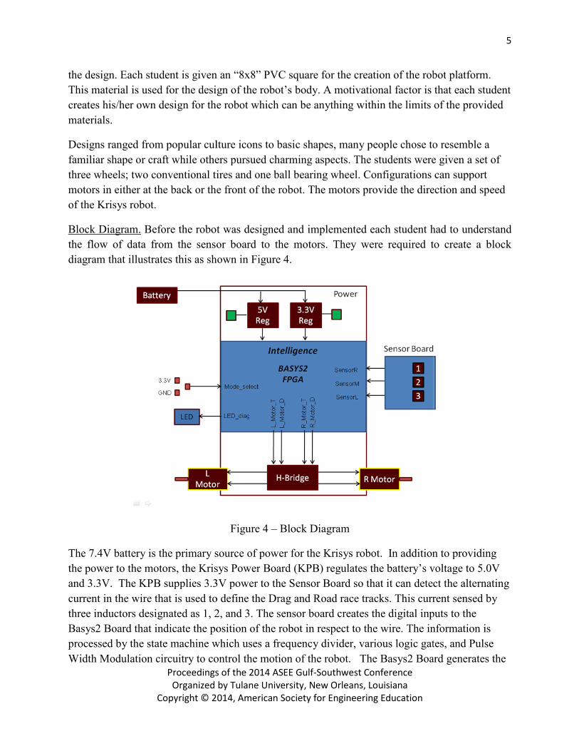
Block Diagram. Before the robot was
the flow of data from the sensor board to the motors. They were required to create a block
diagram that illustrates this as shown in Figure 4
The 7.4V battery is the primary source of power for the Krisys robot. In addition to providing
the power to the motors, the Krisys Power
and 3.3V. The KPB supplies 3.3V power to
current in the wire that is used to define the Drag and Road race
three inductors designated as 1, 2, and 3
Basys2 Board that indicate the pos
processed by the state machine which uses a
Width Modulation circuitry to control the motion of the robot. T
Proceedings of the 2014 ASEE Gulf-Southwest Conference
Organized by Tulane University, New Orleans, Louisiana
Copyright © 2014, American Society for Engineering Education
student is given an “8x8” PVC square for the creation of the robot
design of the robot’s body. A motivational factor is
creates his/her own design for the robot which can be anything within the limits of the provided
ns ranged from popular culture icons to basic shapes, many people chose to resemble a
familiar shape or craft while others pursued charming aspects. The students were given a set of
three wheels; two conventional tires and one ball bearing wheel. Configurations can support
back or the front of the robot. The motors provide the direction and speed
Before the robot was designed and implemented each student had to
the flow of data from the sensor board to the motors. They were required to create a block
trates this as shown in Figure 4.
Figure 4 – Block Diagram
The 7.4V battery is the primary source of power for the Krisys robot. In addition to providing
Krisys Power Board (KPB) regulates the battery’s voltage to 5.0V
supplies 3.3V power to the Sensor Board so that it can detect
in the wire that is used to define the Drag and Road race tracks. This current sensed
1, 2, and 3. The sensor board creates the digital inputs to
that indicate the position of the robot in respect to the wire. The information
state machine which uses a frequency divider, various logic gates, and Pulse
dulation circuitry to control the motion of the robot. The Basys2 Board generates the
5
for the creation of the robot platform.
is that each student
s of the provided
, many people chose to resemble a
he students were given a set of
s can support
he motors provide the direction and speed
each student had to understand
the flow of data from the sensor board to the motors. They were required to create a block
The 7.4V battery is the primary source of power for the Krisys robot. In addition to providing
PB) regulates the battery’s voltage to 5.0V
it can detect the alternating
tracks. This current sensed by
creates the digital inputs to the
. The information is
logic gates, and Pulse
ard generates the

Proceedings of the 2014 ASEE Gulf
Organized by Tulane Uni
Copyright © 2014, America
two PWM signals for the left and
amplifies the signals to the intended motor. The motors then rotate
the PWM while their direction is controlled by the control algorithm dev
These algorithms can include the ability for the robot to reverse its direction should it become
lost.
Electronics. Each student is issued
The Basys2 Board is capable of hosting
applications. Figure 5 is a detailed picture of the Basys
that provide constant DC voltages and has
Basys2 Board is powered from 5 volts delivered from the KPB’s regulator
main 5V power input comes from the Krisys Power Board
required to learn how to solder, populate and test their
Board assembly was group oriented
the primary components on the board is the H
signals from the Basys2 Board’s stat
Krisys Power Board uses a phoenix
when the Krisys Power Board’s regulators are supplying the 3.3V and 5V output.
Also powered by the Krisys Power Board is the Sensor B
Figure 7 provides active low signals when it senses the alternating current and
output in three small LEDs. The actual sensors are inductors located underneath the board
the sensitivity of each sensor can be adjusted
small green LED is to show that it is powered. The sensor board is interfaced to the
Board using the six pin I/O ports next to the three LEDs.
Figure 5 – Basys2 Board
Proceedings of the 2014 ASEE Gulf-Southwest Conference
Organized by Tulane University, New Orleans, Louisiana
Copyright © 2014, American Society for Engineering Education
and right motors and sends these signals to the H-bridge which
to the intended motor. The motors then rotate at the speed established by
while their direction is controlled by the control algorithm developed by the student
These algorithms can include the ability for the robot to reverse its direction should it become
ach student is issued a Basys2 Board that operates as the brain of the
hosting Multisim designs for monitoring and control
a detailed picture of the Basys2 Board. It includes a series of switches
that provide constant DC voltages and has pushbuttons for a press and hold activation. The
5 volts delivered from the KPB’s regulator. The Basys2 Board’s
main 5V power input comes from the Krisys Power Board shown in Figure 6. Studen
populate and test their Krisys Power Board. The Krisys Power
Board assembly was group oriented, but required each student to build his/her own
on the board is the H-Bridge which converts the direction and
’s state machine to the primary drive signals for the
uses a phoenix connector as the battery input, and the red LEDs indicat
when the Krisys Power Board’s regulators are supplying the 3.3V and 5V output.
Also powered by the Krisys Power Board is the Sensor Board. The Sensor Board
signals when it senses the alternating current and illustrates the
The actual sensors are inductors located underneath the board
the sensitivity of each sensor can be adjusted individually through its associate potentiometer
to show that it is powered. The sensor board is interfaced to the
I/O ports next to the three LEDs.
Battery
Connection H-Bridge
Figure 6 – Krisys Power Board (KPB)
6
bridge which
speed established by
eloped by the student.
These algorithms can include the ability for the robot to reverse its direction should it become
2 Board that operates as the brain of the Krisys robot.
for monitoring and control
It includes a series of switches
activation. The
The Basys2 Board’s
tudents were
The Krisys Power
but required each student to build his/her own board. One of
the direction and PWM
the motors. The
red LEDs indicate
when the Krisys Power Board’s regulators are supplying the 3.3V and 5V output.
oard shown in
illustrates the
The actual sensors are inductors located underneath the board and
individually through its associate potentiometer. A
to show that it is powered. The sensor board is interfaced to the Basys2
Bridge
Krisys Power Board (KPB)

Proceedings of the 2014 ASEE Gulf
Organized by Tulane Uni
Copyright © 2014, America
Final Project Summary: Digital Design
Digital Design. The digital design of the Krisys robot is the main focus of this course. Students
are in charge of designing, implementing, and testing the circuitry that constitutes the
intelligence of the Krisys robot. Figure 8
Basys2 Board. The design is composed of
inputs (L, S, and R) from the Sensor Board and sends control values to
Width Modulation circuits.
Frequency Divider. A frequency divider
master clock to the frequency necessary
Figure 8
Reduce
d
L
S
R
State
Inputs
from
sensor
board
Frequency
Divider Basys2
Master
Clock
Outputs
from
State
Machin
e
5 bit
5 bit
Inductors (alternating current
sensors)
Left Center
Proceedings of the 2014 ASEE Gulf-Southwest Conference
Organized by Tulane University, New Orleans, Louisiana
Copyright © 2014, American Society for Engineering Education
Figure 7 – Sensor Board
: Digital Design
The digital design of the Krisys robot is the main focus of this course. Students
are in charge of designing, implementing, and testing the circuitry that constitutes the
e of the Krisys robot. Figure 8 is a block diagram of the circuitry progr
The design is composed of a state machine that receives three digital, active low
, and R) from the Sensor Board and sends control values to two independent
A frequency divider is used to reduce the frequency of the Basys2 Board’s
necessary to produce PWM signals at the required frequency
Figure 8 – Digital Design Block
Diagram
A
B
A
B
G
E
5-bit
Comparato
5-bit
Counter
G
E
5-bit
Comparato
Control
value
Control
value
Reduce
d
5-bit
Counter
PW
MSig
nal
Moto
PW
M
Signa
l
PWM
Y
PWM
X Reduced Frequency (160 kHz)
(5 k
(5 kHz
Inductors (alternating current
Center Right
7
The digital design of the Krisys robot is the main focus of this course. Students
are in charge of designing, implementing, and testing the circuitry that constitutes the
programmed into the
digital, active low
two independent Pulse
Basys2 Board’s
produce PWM signals at the required frequency. The
Three LEDs
Sensitivity
adjustment
potentiometers
PW
Sig
nal
Moto
PW
M
Signa
l
PWM -
PWM -
kHz)
Hz)

8
Proceedings of the 2014 ASEE Gulf-Southwest Conference
Organized by Tulane University, New Orleans, Louisiana
Copyright © 2014, American Society for Engineering Education
frequency divider must reduce the master clock’s 50MHz frequency of the Basys2 Board to
provide 5KHz PWM signals for each motor. A frequency divider as indicated in equation (1) is a
circuit that accepts an input frequency of “fin” and generates an output frequency of “fout”.
�1� �� ���
�
Where ‘‘N’’ is an integer. A frequency divider is composed of a series of counters cascaded together. The input frequency
of the counter (fin = 50MHz), or the Master clock, is a high frequency that needs to be reduced
in order to obtain a lower frequency (fout= 160kHz) that will be sent to the PWM’s counter in
order to generate a resultant PWM frequency of 5kHz. In equation (2), “N” will represent a
number of counts given by the formula:
�2� # �� �� � ��� � 2� � �� Where “n” is the number of bits of the frequency divider and “min” is the initial value that is
loaded into the counter to achieve the Divide-by-N conversion of the master clock.
Figure 9 illustrates a frequency divider composed of two 4-bit counters cascaded together. These
counters are cascaded by using the RCO signal which outputs a 1 whenever the counter reaches
its maximum value. The RCO signal of each counter is tied to the enables (T, P) of the next
counter being cascaded, which activates it.
The RCO output of the last counter is inverted and tied to the load (LD) input of all the counters,
so once it reaches its maximum value, the counter will reload the minimum value that was select
to generate the proper Divide-by-N operation.
The output frequency of the Divide-by-N counter is a function of the n-bit comparator and the
desired output frequency of the PWM circuit. For the design of the robot, a 5 bit counter was
used and the desired PWM frequency was 5kHz, thus the required output frequency (fout) was
160 KHz. The frequency of the Basys2 Board (fin) is 50 MHz and by rearranging equation (1)
the number of counts “N” of the frequency divider is equal to 313. By rearranging equation (2)
Figure 9- Divide-by-N Frequency Divider
Max Value = 2� � 1
fin
T
P
RCO
LD
CL
D C B A
QD QC QB QA T
P
RCO
LD
CL
D C B A
QD QC QB QA
1
1
1
fout
min value

9
Proceedings of the 2014 ASEE Gulf-Southwest Conference
Organized by Tulane University, New Orleans, Louisiana
Copyright © 2014, American Society for Engineering Education
the minimum value (min) of the design’s frequency divider was set to 3,783. Figure 10 is the
frequency divider that was implemented in Multisim.
This frequency divider is composed of three 4-bit counters with a minimum value of 3,783 and a
maximum value of 4,095 (2^n- 1). The FCLOCK pin represents the frequency that will be sent to
the PWM’s counters (160kHz).
Pulse Width Modulation. Pulse Width Modulation is a technique that produces simulated analog
values using digital signals. Digital control is used to create a square wave, a signal switched
between on and off. This on-off pattern can be used to simulate voltages in between full on (5
Volts) and off (0 Volts) by changing the portion of the time the signal spends on versus the time
that the signal spends is both on and off (period). The duration of "on time" is called the pulse
width. To get varying analog values, you change, or modulate, the pulse width while maintaining
the frequency of the waveform. The amount of voltage delivered to the motors depends on the
duty cycle of the PWM. Duty cycle as shown in equation (3) is the percent of time a signal is in
its active state as a fraction of the total period of the signal.
�3� %�� ����� ����� �
�������100
The voltage delivered to the Krisys robot as shown in equation (4) is approximately equal to the product of the maximum voltage of the motor and the duty cycle of the PWM.
�4� "��� #��$%� � "$� #��$%� · �. �. �("
Figure 10- Frequency divider circuitry
RCO
fout
Basys2
Frequency
(fin) Inputs/
minimum
value of
Frequency
divider

10
Proceedings of the 2014 ASEE Gulf-Southwest Conference
Organized by Tulane University, New Orleans, Louisiana
Copyright © 2014, American Society for Engineering Education
Figure 11 depicts five different duty cycles based on the time the signal is on and off.
The green lines in Figure 11 represent one period; this period is the inverse of the frequency of the PWM waveform. The time that the signal stays in its active state (pulse width) is proportional to the duty cycle of the PWM; as the active state of the signal increases the amount of voltage sent to the motors increases.
As shown in Figure 8, a pulse width modulation circuit can be created using an n-bit counter and n-bit comparator. The PWM generator used for this design employs 5-bit components. By altering the control values (input B- Figure 8), the duty cycle of a PWM signal can be varied. Depending on which comparator outputs are OR together, the formula for the duty cycle will change. In the implemented design the Equal to (E) and Less than (L) outputs were ORed, thus equation (5) is used to obtain the PWM’s duty cycle.
�5� �� ����� �* + 1
2�
Where “B” is the control value that is generated by the state machine and “n” is the size in bits of the PWM components. In Table 1 controlled values and resulting duty cycle are presented. As seen in Table 1, as the control value increases the duty cycle increases, thus increasing the power sent to the motor. A binary representation of the controlled values, as well as the weight of each output bit according to its position, is also included.
Table 1- Controlled values and resulting duty
cycles
Figure 11 – Duty Cycles
Controlled
values
State Machine
Outputs/ Binary
Representation
Output
weight
%Duty Cycle

11
Proceedings of the 2014 ASEE Gulf-Southwest Conference
Organized by Tulane University, New Orleans, Louisiana
Copyright © 2014, American Society for Engineering Education
Control over the incremental increase or decrease of the PWM can be changed by modifying the pulse width modulator’s resolution. This is possible by modifying the number of bits (n) used in the PWM circuitry. For this design (5-bit PWM) the resolution is 3.125%. One PWM circuit per motor is needed and added to the digital design of the complete system. Figure 12 is the PWM designed for the Krisys robot.
A 5-bit counter and two cascaded 4-bit comparators were used to build the design’s PWM
circuitry. The outputs of the counter (A1-E1) and state machine (O0-O4) are sent to the
comparators as inputs. The equal (E) and less than (L) outputs are ORed together to obtain the
desire PWM signal.
State Machine. A state diagram, also called a state machine diagram, is a diagram of the states a
system can attain and the system’s transitions between those states. Figure 13 is a representation
of a simple state machine diagram.
Inputs/Conditional outputs Unconditional
outputs
Unconditional
outputs
S0* S1
Figure 13- State Machine Diagram
Figure 12- PWM Digital Design
Five-bit
Counter
PWM signal

12
Proceedings of the 2014 ASEE Gulf-Southwest Conference
Organized by Tulane University, New Orleans, Louisiana
Copyright © 2014, American Society for Engineering Education
States S0 and S1 are represented as circles. Arrows indicate transition between states and include inputs and, depending on the design, conditional outputs. Unconditional outputs are incorporated inside the circles. For the Krisys robot design it was decided to implement a 5-bit PWM, as a result, the state machine had a total of 12 outputs; 5 per each PWM and 2 more to control the direction of each motor. The state machine for the robot was developed with the intent of following both a Drag and Road race track autonomously. In case the sensors detected the line in any other position that is not the center (101), the PWM control outputs of the state machine would change with the purpose of correcting the course of the Krisys robot. Figure 14 is the state machine diagram designed to control the Krisys robot.
The state machine diagram has only 3 inputs which are located on the arrows L,S, and R. The
state named S0* represents the initial state of the Krisys Robot and provides PWM control
values that will cause the robot to move in straight line. As the inputs L,S,R change, the Krisys
robot transitions into a new state with different PWM control values. Depending on the inputs
that the state machine receives, the Krisys robot will move between states generating different
control values that will be sent to the PWM circuits. State Machines can be implemented in
Figure 14 – State Machine Diagram
13
Proceedings of the 2014 ASEE Gulf-Southwest Conference
Organized by Tulane University, New Orleans, Louisiana
Copyright © 2014, American Society for Engineering Education
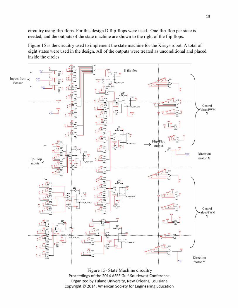
circuitry using flip-flops. For this design D flip-flops were used. One flip-flop per state is
needed, and the outputs of the state machine are shown to the right of the flip flops.
Figure 15 is the circuitry used to implement the state machine for the Krisys robot. A total of
eight states were used in the design. All of the outputs were treated as unconditional and placed
inside the circles.
D flip-flop
Control
Values/PWM
X
Inputs from
Sensor
Board
Flip-Flop
inputs
Control
values/PWM
Y
Direction
motor Y
Figure 15- State Machine circuitry
Direction
motor X
Flip-Flop
output

14
Proceedings of the 2014 ASEE Gulf-Southwest Conference
Organized by Tulane University, New Orleans, Louisiana
Copyright © 2014, American Society for Engineering Education
The outputs from the sensor board and outputs from the different flip-flops are used create the
inputs to the state machine flip-flops that will cause the proper state transitions based on the
current state and current inputs. What inputs go into each flip-flop depends on the design.
According to the current state of the machine, the flip flops will send a predetermined control
value to each PWM circuit. This control value will define the duty cycle, and thus, the speed of
each of the motors. This state machine can also control the direction of the motors.
Calibration/Optimization. To calibrate the Krisys robot the potentiometers on the sensor board
are used. By increasing/decreasing the sensitivity of the inductors, the precision of the robot is
enhanced, this means that the robot’s accuracy in detecting its exact position on the track
improves. When calibrating the sensor board the user should be able to replicate all of the output
combinations shown in Table 2 (0=light off, 1=light on):
Sensor Outputs Meaning
101 On Middle Sensor
001 Between Left and Middle Sensor
011 On Left Sensor
100 Between Right and Middle Sensor 110 On Right Sensor
111 Lost
010 Impossible combination
000 Impossible combination
The optimization process requires the use of a test track. There, the user is able to observe the behavior of the Krisys robot in the real world. When designing the state machine provisional duty cycles are used. Once the design is complete and those duty cycles are tested, the user can decide whether to increase or decrease the duty cycles in any of the states. The optimization process continues until the optimum duty cycles are empirically determined.
Lessons Learned: In the industrial world engineers follow a set of guidelines universally known as the Engineering Design Process. This process uses a methodical approach to problem solving with the intent of breaking down the task of finding a solution, into steps. Thanks to the Xilinx Race of Champions, students were able to experience this process by taking a problem and developing a functional prototype to solve it. This experience gave students an insight on what it takes to develop a product; from brainstorming a digital and mechanical design for the Krysis robot, to optimizing its performance before the competition. Finding creative ways of following the track, considering constrains and criteria when choosing a feasible design and optimizing the intelligence of the robot, are some example of the variety of task students undergo and that enhance the students’ skills. Students were able to design, develop, implement, test, and optimize
Table 2- Krysis Robot Calibration

15
Proceedings of the 2014 ASEE Gulf-Southwest Conference
Organized by Tulane University, New Orleans, Louisiana
Copyright © 2014, American Society for Engineering Education
a system in an introductory course to this major. In this course, students learned to modify, test, and simulate circuitry essential to produce a prototype; this circuitry included combinatorial and sequential logic design. They learned functions of different devices such as flip-flops, decoders, multiplexer, and comparators. In order to take their design from theoretical to reality, they learned how to solder and modify electrical devices. In the mechanical aspect, they designed crafts that were able to carry the electronics and design interesting vehicles using given supplies. In order to simulate the performance of their digital design before testing it in their robot, they learned to use an electronic schematic capture and simulation protocol known as Multisim. In ENTC 219 students learned the building blocks and fundamentals of theoretical design and with the final project they had the opportunity to implement this theoretical knowledge into the real world, thus reasserting their understanding.
Recommendations:
We recommend that every student should purchase a notebook to catalog and organize the concepts learned in ENTC 219 because these concepts will be applied all throughout the ESET degree and their future career. The notebook should have strictly fundamental knowledge that is used to generalize the implementation of a device such as a multiplexer. Practicing these concepts and usage of the devices can be monitored and explored in Multisim, so it is recommended for students to make use of this useful tool. Properly understanding these devices and knowing how to apply them in the real world will enhance the student’s capability to properly design the final project with much more precision and accuracy. For the final project we recommend that students manage their time wisely in order to have the required time to calibrate and optimize their prototype. Many prototypes failed because they were not properly tested before the race. Most importantly, we suggest that students take the final project as an opportunity to challenge themselves and go beyond what is expected; think outside of the box and aim for a digital and mechanical design that surpasses expectations.