kraus & naimer - renewable energy · pdf fileguide to the selection of ac & dc...
TRANSCRIPT

Guide to the selection of AC & DC Switch-Disconnectors for Photovoltaic Systems 2014
B L U E L I N E s w i t c h g e a r s i n c e 1 9 0 7
Kraus & Naimer

www.krausnaimer.co.uk
2
www.krausnaimer.co.uk
3
Inverter
Local AC Switch-Disconnector
Local DC Switch-Disconnector
The development of the Blue Line rotary switch is based on more than one hundred years experience by Kraus & Naimer in the design
and manufacture of electrical switchgear.
Kraus & Naimer pioneered the introduction of the cam operated rotary switch and continues to be recognized as the world leader in that product field.
Blue Line products are protected by numerous patents throughout the industrial world. They are built to national and international standards and designed to withstand adverse temperatures and climates. Our extensive
range includes cam operated rotary switches up to 2400A, main/main emergency-off switch-disconnectors up to 1250A and changeover switches up to 2400A. They can be supplied for mounting on machines, in switch panels or in
enclosures using materials such as polycarbonate, GRP, painted mild steel and stainless steel.
Kraus & Naimer's Blue Line products are accepted and universally recognised for their quality and workmanship.
Kraus & Naimer Limited is part of the worldwide Kraus & Naimer Group which celebrated its 100 year anniversary in 2007.
In 1963, Kraus & Naimer Limited was established as the UK sales and marketing company for Kraus & Naimer switchgear. By the early 70’s successful growth meant a move to its current purpose-built premises in
Newbury, where it supplies over 3,000 customers with world-renowned, high quality Blue Line switchgear products.
A key to our success is the outstanding level of technical product support through our dedicated team of internal and external technical sales engineers. With many years experience, training and unbeatable product knowledge
the team can find a suitable solution for most switch applications.
AC & DC switch-disconnectors for photovoltaic systems At Kraus & Naimer our extensive experience in the design and manufacture of electrical switchgear ensures we are able to help installers, wholesalers, training centres and design engineers with the correct selection of our products in relation to their applications.
There is a distinct need for information on the selection of AC & DC switch-disconnectors for photovoltaic systems. For customers who are new to the PV market, the equipment used in the systems and particularly the challenge of working with DC can be confusing.
We hope this guide will be welcomed and encourage any queries with regard to the selection of switch-disconnectors. Questions can be made direct to our experienced sales team or our technical department.
What you will find in this guide:
1. An explanation of switch-disconnectors
2. Information on relevant standards and guides
3. An explanation of utilisation categories
4. AC switch-disconnector selection criteria
5. DC switch-disconnector selection criteria
6. Example systems & further DC information
7. Current selection charts & price lists
8. Product data & connection diagrams

www.krausnaimer.co.uk www.krausnaimer.co.uk
4 5
Switch-DisconnectorsThe requirements for switch-disconnectors for use on electrical installations within the UK are specified by BS 7671:2008+A1, IET Wiring Regulations. The requirements for isolation and switching are contained in Chapter 53, Section 537; plus specific information relating to PV systems; which is given in section 712.
Kraus & Naimer’s switch-disconnectors are designed and manufactured in accordance with the requirements of BS EN 60947-3; which is listed in table 53.4 of BS 7671 as being an appropriate standard for isolation.
It is important to note that the use of switches for safety isolation (i.e. not designated as a disconnector or switch-disconnector) is contrary to BS 7671 and hence the EU’s low voltage directive. Therefore only a device designated as a disconnector or switch-disconnector can be used for the purpose of safety isolation of an electrical circuit.
BS EN 60947-3 is the relevant standard for manually operated industrial switch products. The standard defines the following product types;
a) Switch A device capable of making, carrying and breaking current within an electrical circuit under defined conditions.
b) Disconnector A device capable of carrying current within an electrical circuit and providing off-load isolation within that circuit in accordance with the specified requirements for safety isolation. c) Switch-Disconnector
A device capable of complying with the requirements for both Switch and Disconnector devices; i.e. provides on-load isolation and operational switching.
In stating a product’s compliance with BS EN 60947-3, the manufacturer must state the product type that applies and the product must be clearly marked with the designated symbol for the appropriate product type. The appropriate symbols are below.
Switch Disconnector Switch-Disconnector
Other relevant PV guides/standards
• DTI publication “Guide to the installation of PV systems” - 2nd edition
• “Guide to the installation of PV systems” - 3rd edition, IN DRAFT
• IEC 62548 edition 1: Design requirements for photovoltaic (PV) arrays, IN DRAFT
• BS EN 62446 - Grid connected photovoltaic systems. Minimum requirements for system
documentation, commissioning tests and inspection.
• IEC 62257-7-1 edition 2 - Recommendations for small renewable energy and hybrid systems for
rural electrification, part 7-1: Generators - Photovoltaic generators.
• IEC 60364-7-712 edition 1 - Electrical installations of buildings - Part 7-712: Requirements for
special installations or locations - Solar photovoltaic (PV) power supply systems
Utilisation Categories
Utilisation categories simplify the selection of devices. Examples of utilisation categories for low voltage switchgear and controlgear together with the relevant product standards are given in BS EN 60947-1, Annex A. It is the characteristics of the load to be switched and its application that determine the required rating of the switchgear. Utilisation categories take into account the intended applications and the associated rating of the switchgear which prevents customers being confused by technical details.
Manufacturer’s technical data provides rated operational currents/powers for various rated operational voltages and utilisation categories. This helps users and design engineers in the selection of the correct switchgear.
The rated operational current, voltage and utilisation category determine the suitability of a device for its intended application, one device may have a rating for a variety of different utilisation categories.
Utilisation categories typically used in PV systems are;
AC AC-21 - Switching of resistive loads, including moderate overloads AC-22 - Switching of mixed resistive and inductive loads, including moderate overloads
DC DC-21 - Switching of resistive loads, including moderate overloads DC-22 - Switching of mixed resistive and inductive loads, including moderate overloads
The designation of some utilisation categories are completed by the suffix A or B according to whether the intended application requires frequent or infrequent operations.
Utilisation categories with the suffix B are appropriate for devices which, due to design or application, are only intended for infrequent operation. This could apply, for example, to switch-disconnectors normally only operated to provide isolation for maintenance work.
When stating product compliance with BS EN 60947-3 for a given utilisation category there are a number of mandatory tests which need be completed, one of these tests in BS EN 60947 parts 1 & 3 is the ‘Operational Performance test’, below is some extracted data from section 7.2.4.2 of BS EN 60947-3.
The below tests are required as a minimum for compliance with the standard.
Verification of operational performance for rated operational current of 0 - 100A
UtilisationCategory without current with current TotalDC-22A 8500 1500 10,000DC-22B 1700 300 2000DC-21A 8500 1500 10,000DC-21B 1700 300 2000
Number of test operations

www.krausnaimer.co.uk www.krausnaimer.co.uk
6 7
AC Switch-Disconnector Selection Criteria
The method of selection is mainly based on general engineering practice with some additional factors applicable to grid connected PV systems. For the AC switch-disconnector the public supply should be considered the source and the PV installation the load.
In grid connected PV systems a Lockable switch-disconnector must be located in an accessible position in the premises, for example adjacent to the consumer unit. Typically if the switch-disconnector and inverter are not in the same location, then an additional local switch-disconnector should be installed adjacent to the inverter (this is to facilitate maintenance of the AC cable run and inverter).
Switch-disconnectors complying with BS EN 60947-3 are appropriate for use in PV systems as specified in BS 7671, for further details see the standard.
Principle factors to be considered when selecting the AC switch-disconnector.
1. Number of poles 2 Pole - Single phase, typically for domestic installations. 4 Pole - Three phase + neutral, typically for larger commercial installations.
2. Rated voltage & current Voltage & current - based on the output of the inverter, these figures are typically given as per phase (line to neutral) values in the inverter datasheets i.e. for a three phase inverter they may give 16A at 230V. For three phase output the switch must be suitably rated for the line to line voltage, typically 415V.
3. Correct Utilisation category - typically AC-21A or AC-22A
4. The ambient temperature where the switch-disconnector is to be installed Industrial enclosed AC switch-disconnectors are normally rated for use in an environment with an ambient temperature of 35°C, which will be fine for most installations. If the switch-disconnector is installed in an area where ambient temperatures are higher, such as a loft space, then a switch- disconnector capable of handling ambient temperatures of 50°C may be required (most inverters are suitably rated for use in environments with an ambient temperature of 50°C).
5. Cable sizeThe switch terminal capacity must be suitable for the size of cable and type of termination used. Our catalogues detail this information or see page 15 of this guide. Required cable size is determined by the rated load current, volt-drop, ambient temperature and type of cable being used. However, on PV installations, the size of the cable is frequently determined by the inverter requirements. This is due to the fact that most grid connected inverters have set parameters on grid impedance of the AC cable. Many inverter companies will include a table in their installation or technical manuals which gives information on the size of cable and the maximum length to suit their requirements.
6. Short circuit & overload protection deviceFuse or circuit breaker protection must be provided at connection to the consumer unit. The maximum back-up fuse rating for Kraus & Naimer switches is shown in the table below. The actual rating of the fuse/circuit breaker will normally be lower, with the value being determined by the cable or inverter requirement.
Switch Type Short Circuit ProtectionKG20 35AKG32 35AKG41 50A
The list of above mentioned factors is not in anyway to be viewed as an exhaustive list, selection criteria will vary from installation to installation.
DC Switch-Disconnector Selection Criteria
DC is inherently more difficult to interrupt than AC. Alternating currentpasses the zero point twice each cycle. Direct current is constant and will not drop to zero unless the supply is disconnected.
When breaking DC under load an arc is created, once there is enough resistance built up the arc will break. It is vital to break the arc quickly. There are a number of ways to achieve this and one common method used is the series connection of contacts. This will increase the air gap and stretch and suppress the arc without damaging the contacts. This method improves switching capacity, contact life and allows higher operating voltages.
It is a requirement of BS 7671 that a switch-disconnector shall be provided on the DC side of a PV installation, the standard for switch-disconnectors is BS EN 60947-3.
Principle factors to be considered when selecting the DC switch-disconnector.
1. Number of strings to be isolated 2 Pole - Single string, 4 Pole - Two string, etc. It is considered good practice to use 1 isolator per string. However, 2 string isolators are available.
2. Rated current & voltage
Voltage calculations; The rated operational voltage of the switch should be equal to or greater than the product of open circuit voltages (Voc) and correction factors as per current standards e.g. total of series connected PV panels x Voc of an individual panel x correction factor (1.15).
Current calculations; The rated operational current of the switch should be equal to or greater than the product of short circuit currents (Isc) and correction factors as per current standards e.g. total of parallel connected PV strings x Isc of an individual panel x correction factor (1.25).
3. Correct Utilisation category - typically DC-21B, but DC-21A, DC-22/A or B can be used.
4. The ambient temperature where the switch-disconnector is to be installedIf the switch-disconnector is installed in an area where ambient temperatures are higher, i.e. a loft space, then a switch-disconnector capable of handling ambient temperatures of 50°C may be required (most inverters are suitably rated for use in environments with an ambient temperature of 50°C). All of our DC enclosed range are rated for use at 50°C.
5. Cable sizeThe switch terminal capacity must be suitable for the size of cable and type of termination used. Our catalogues detail this information or see page 15 of this guide.
Required cable size is determined by the rated load current (base on calculation in point 2 above), volt-drop, ambient temperature and type of cable being used (normally double insulated).
The list of above mentioned factors is not in anyway to be viewed as an exhaustive list, selection criteria will vary from installation to installation.
DC AC
V/I
t t
00
V/I
www.krausnaimer.co.uk www.krausnaimer.co.uk
8 9
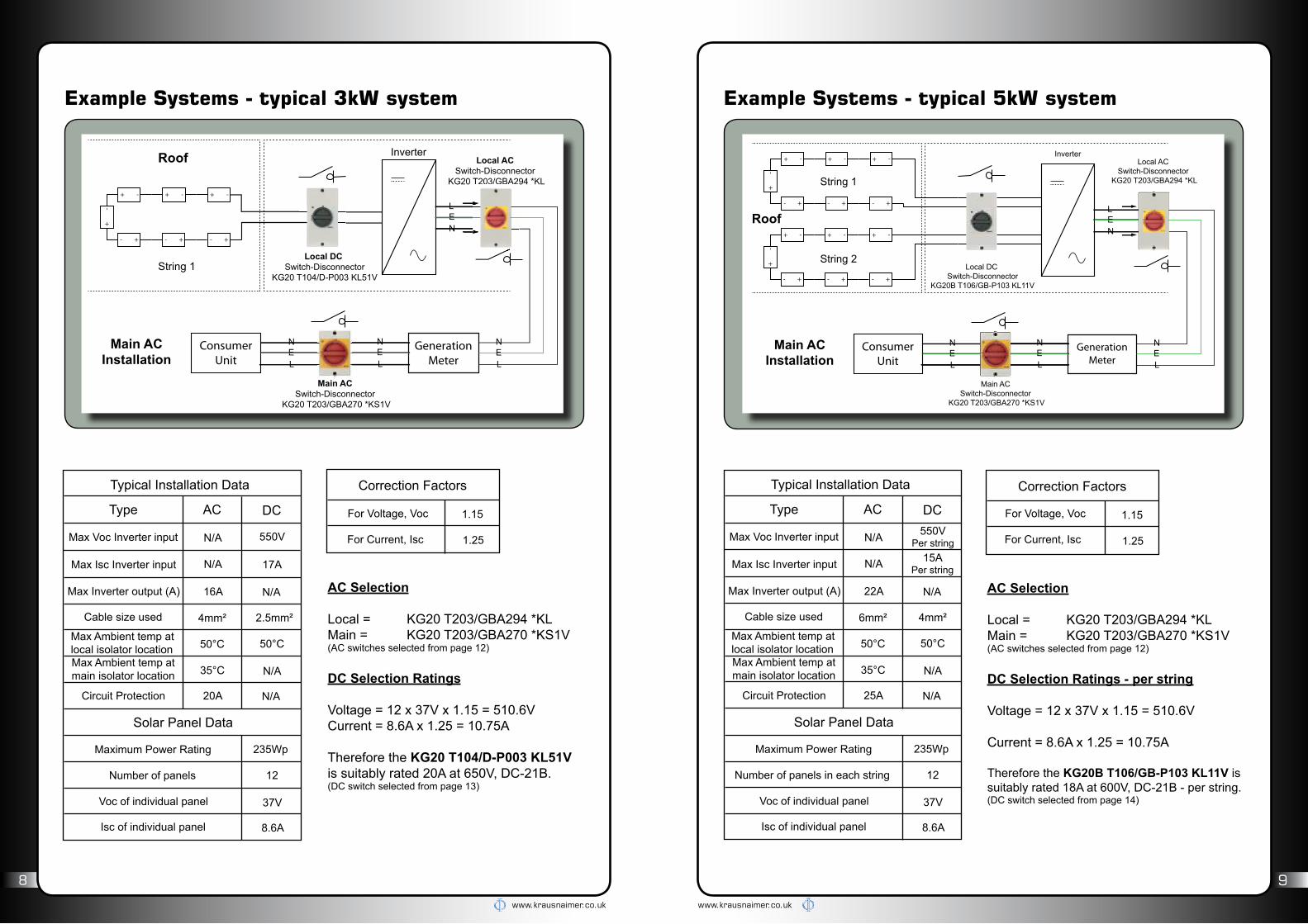
Correction Factors
For Voltage, Voc
For Current, Isc
1.15
1.25
AC Selection
Local = KG20 T203/GBA294 *KLMain = KG20 T203/GBA270 *KS1V(AC switches selected from page 12)
DC Selection Ratings
Voltage = 12 x 37V x 1.15 = 510.6VCurrent = 8.6A x 1.25 = 10.75A
Therefore the KG20 T104/D-P003 KL51Vis suitably rated 20A at 650V, DC-21B. (DC switch selected from page 13)
Example Systems - typical 5kW system
Typical Installation Data
Type AC DC
Max Isc Inverter input
Max Inverter output (A)
Cable size used
Max Ambient temp atlocal isolator locationMax Ambient temp atmain isolator location
Circuit Protection
Solar Panel Data
Maximum Power Rating
Number of panels in each string
Voc of individual panel
Isc of individual panel
N/A
22A
25A
15APer string
N/A
4mm²
N/A
N/A
6mm²
50°C50°C
35°C
235Wp
37V
8.6A
12
Correction Factors
1.15
1.25
AC Selection
Local = KG20 T203/GBA294 *KLMain = KG20 T203/GBA270 *KS1V (AC switches selected from page 12)
DC Selection Ratings - per string
Voltage = 12 x 37V x 1.15 = 510.6V
Current = 8.6A x 1.25 = 10.75A
Therefore the KG20B T106/GB-P103 KL11V is suitably rated 18A at 600V, DC-21B - per string. (DC switch selected from page 14)
Max Voc Inverter input N/A 550VPer string
Example Systems - typical 3kW system
Typical Installation Data
Type AC DC
Max Isc Inverter input
Max Inverter output (A)
Cable size used
Max Ambient temp atlocal isolator locationMax Ambient temp atmain isolator location
Circuit Protection
Solar Panel Data
Maximum Power Rating
Number of panels
Voc of individual panel
Isc of individual panel
N/A
16A
20A
17A
N/A
2.5mm²
N/A
N/A
4mm²
50°C50°C
35°C
235Wp
37V
8.6A
12
Max Voc Inverter input N/A 550V
For Voltage, Voc
For Current, Isc
GenerationMeter
ConsumerUnit
+ -+ - + -
+ -
+
-
+ - + -
Inverter
GenerationMeter
Local AC Switch-Disconnector
KG20 T203/GBA294 *KL
Main AC Switch-Disconnector
KG20 T203/GBA270 *KS1V
ConsumerUnit
String 2
+ -+ - + -
+ -
+
-
+ - + -
String 1
+ -+ - + -
+ -
+
-
+ - + -
Local DC Switch-Disconnector
KG20B T106/GB-P103 KL11V
Roof
Main ACInstallation
L
NE
N
LE
N
LE
N
LE

www.krausnaimer.co.uk www.krausnaimer.co.uk
10 11
DC Voltage & Current in PV Systems
Product Range
AC Selection
P/room = KG41 T204/GBA290 *KL1VMain = KG41 T204/GBA290 *KL1V
KG41 has to be used only due to cable size on AC side of installation.(AC switches selected from page 12)
DC Selection Ratings
Panel setup = 3 strings to input A & 1 string to Input B.1 isolator per string required.
Voltage = A = 17 x 37V x 1.15 = 723.4V B = 14 x 37V x 1.15 = 595.7V
Current = 8.6A x 1.25 = 10.75A
Therefore the KG20 T104/D-P003 KL51Vis suitably rated 18A at 800V, DC-21B. (DC switch selected from page 13)
Input A = 33AInput B = 11A
6mm²10mm²
Input A = 17Input B = 14
Example Systems - typical 15kW system
DC Voltages in PV systems:
DC Voltage in PV systems is determined by the solar panel output and how the MPPT controls it.Voltage values for the DC isolator selection is based on the Voc multiplied by a correction factor (generally a 1.15 multiplication in the UK) as outlined in current standards / guidance documents.
At present the ceiling value for PV systems is 1000V DC, this is the maximum voltage given by solar panel and inverter manufacturers alike. Typically you will find a statement like “the following limiting values at the DC input of the inverter may not be exceeded” or “the maximum open circuit voltage (Voc), which can occur at a cell temperature of -10°C, may not exceed the maximum input voltage of 1000V”.
DC Currents in PV systems:
DC Current in PV systems is determined by the solar panel output and how the MPPT controls it.Current values for the DC isolator selection is based upon the Isc of the panel multiplied by the number of panels or strings there are in parallel and including a correction factor (generally a 1.25 multiplication) as outlined in current standards / guidance documents.
Most solar panels used in the UK have a Isc of between 5A & 9A Isc so typically when a customer isasking for an isolator to isolate 1 series connected string the current should be no more than 11.25A.
If a client were to ask for a DC isolator to isolate 2 strings connected in parallel then it would be nearer 22.5A and so on.
G59Panel
MainDistribution
Board
+ -+ - + -
+ -
+
-
+ - + -
+ -+ - + -
+ -
+
-
+ - + -
+ -+ - + -
+ -
+
-
+ - + -
+ -+ - + -
+ -
+
-
+ - + -
Typical Installation Data
Type AC DC
Max Isc Inverter input
Max Inverter output (A)
Cable size used
Max Ambient temp atlocal isolator locationMax Ambient temp atmain isolator location
Circuit Protection
Solar Panel Data
Maximum Power Rating
Number of panels in each string
Voc of individual panel
Isc of individual panel
N/A
24A
32A
N/A
N/A
N/A
50°C50°C
35°C
235Wp
37V
8.6A
Max Voc Inverter input N/A 1000V
Correction Factors
For Voltage, Voc
For Current, Isc
1.15
1.25

www.krausnaimer.co.uk www.krausnaimer.co.uk
12 13
Switch - Disconnectors, 3 & 4 pole
• IP66/67 Protection
• Red/Yellow Padlockable Handle
• Grey Insulated Enclosure
• Switch Interlocked with lid to prevent
opening in “ON” position
• Earth Terminal
DC Switch Disconnectors for
Photovoltaic AC Switch Disconnectors for
Photovoltaic
450V 500V 650V 800V 920V 1000V Order Code Fig.1) Price
25A 21A 20A 18A 11A KG20 T104/D-P003 KL51V 1 £31.8028A 28A 25A 23A 15A KG32 T104/D-P003 KL51V 1 £36.2040A KG41 T104/D-P003 KL11V 2 £45.70
21A 20A KG20B T106/D-P003 KL11V 2 £46.6425A KG32B T106/D-P003 KL11V 2 £53.60
40A 28A KG41B T106/D-P003 KL11V 3 £74.3625A KG20B T108/D-P003 KL11V 3 £70.88
26A KG32B T108/D-P003 KL11V 3 £79.6840A 28A KG41B T108/D-P003 KL11V 3 £89.20
60A KG80C T106/D-P003 STM 4 £221.3660A KG80C T108/D-P003 STM 4 £242.72
Please select the correct switch-disconnector according to the maximum voltage and current output of all upstream
PV modules, this must include all corrective factors according to relevant standards. 1) For dimensions see page 15
DC Switch Disconnectors - Selection Chart DC21B
Switch - Disconnectors, 2 pole - for single string
• IP66/67 Protection
• Black/Grey Padlockable Handle
• Class II compliant, Grey Insulated Enclosure
• Switch Interlocked with lid to prevent opening in
“ON” position
• Rated for use in ambient temperatures of 50°C
Current Rating AC-21A(per contact) Order Code Fig.2) Price
25A KG20 T203/GBA270*KS1V 5 £23.85
25A KG20 T203/GBA294*KL1) 1 £25.5332A KG32 T203/GBA294*KL1) 1 £29.0040A KG41 T203/GBA270*KL1V 2 £42.16
AC Switch Disconnectors - Single Phase
AC Switch Disconnectors - Three PhaseCurrent Rating AC-21A
(per contact) Order Code Fig.2) Price
25A KG20 T204/GBA290*KS1V 5 £29.48
25A KG20 T204/GBA486 KL51V1) 1 £31.5232A KG32 T204/GBA486 KL51V1) 1 £36.7540A KG41 T204/GBA290*KL1V 2 £47.22
1) Larger enclosure to match KG20/32 T104 DC enclosure 2) For dimensions see page 15

www.krausnaimer.co.uk
14
www.krausnaimer.co.uk
15
M25
100
190
178
M25
M20
85
160
150
M20M
20
82 17
FIG. 1
M25
93 17
FIG. 2
229
250
145124
M25
M25
M25
93 17
FIG. 3
272
300
300272
172 49,3
FIG. 4
.. T104 .. .. T103 ..
=
.. T204 .. .. T203 ..=
M20/M25
85
120
M20/
M20
90 17
FIG. 5
M25
M25
Terminal Capacity / Tightening Torque for Terminal Screws / Cable Stripping Length
Switch TypeTerminal Capacity Tightening Torque for
Terminal Screws
Cable Stripping LengthSingle core /
Stranded wireFlexible wire, with sleeve
KG20 / KG32 6mm² 4mm² 1.25Nm 9mmKG41 / KG64 16mm² 10mm² 1.80Nm 10mmKG80C 50mm² 35mm² 3.00Nm 14mm
Product Data & Connection Diagrams
String 1 String 2
+in
+out
+in
+out
-in
-out
-in
-out
T108
T106
String 1 String 2
+in +out +in +out-in
-out
-in
-out
T104
+in
+out
+in
+out
-in
-out
-in
-out
String 1 String 2
T104
+in -out+out -in +in +out -out -in
T108
T106
+in
+out
-in
-out
T204Connectio
n
Diagrams
ACT203
Sing
le S
trin
gTw
o St
ring
AC
Sing
le S
trin
gTw
o St
ring
DC Switch-Disconnectors - Selection Chart DC-21B
Please select the correct switch-disconnector according to the maximum voltage and current output of all upstream PV
modules, this must include all corrective factors according to relevant standards. 1) For dimensions see page 15
DC Switch Disconnectors for
Photovoltaic
Ratings Per StringOrder Code Fig.1) Price
220V 280V 340V 400V 460V25A 21A 20A 18A 11A KG20 T104/GB-P103 KL51V 1 £31.8028A 28A 25A 23A 15A KG32 T104/GB-P103 KL51V 1 £36.2040A KG41 T104/GB-P103 KL11V 2 £45.70
Ratings Per StringOrder Code Fig.1) Price
330V 420V 510V 600V 690V25A 21A 20A 18A 11A KG20B T106/GB-P103 KL11V 2 £46.6427A 27A 25A 23A 15A KG32B T106/GB-P103 KL11V 2 £53.6040A 28A KG41B T106/GB-P103 KL11V 3 £74.36
Ratings Per StringOrder Code Fig.1) Price
440V 560V 680V 800V 920V25A 21A 20A 18A 11A KG20B T108/GB-P103 KL11V 3 £70.8826A 26A 25A 23A 15A KG32B T108/GB-P103 KL11V 3 £79.6840A 28A KG41B T108/GB-P103 KL11V 3 £89.20
Switch - Disconnectors, 4 pole - for 2 string
• IP66/67 Protection
• Black/Grey Padlockable Handle
• Class II compliant, Grey Insulated Enclosure
• Switch Interlocked with lid to prevent
opening in “ON” position
• Rated for use in ambient temperatures of 50°C

Kraus & Naimer115 London Road,Newbury,Berkshire, RG14 2AH
[email protected] Tel: 01635 262626 Fax: 01635 37807www.krausnaimer.co.uk PV-G-1-01/12