kp-55 installation instruction-08-31-09
TRANSCRIPT

1
KP-55 Preview
Outer lock
How to release the battery housing of inner lock
Please use the
push-pin to
push the hook
of battery
housing.

2
KP-55 Installation
Step1

3
Step2
Adjust the dead bolt
Adjust the latch
bolt by pushing
hole.
Lift pin and
pull the body
to the right.
2-3/ 8”
2-3/ 4”
60mm
70mm
2-3/ 8”
2-3/ 4”
4
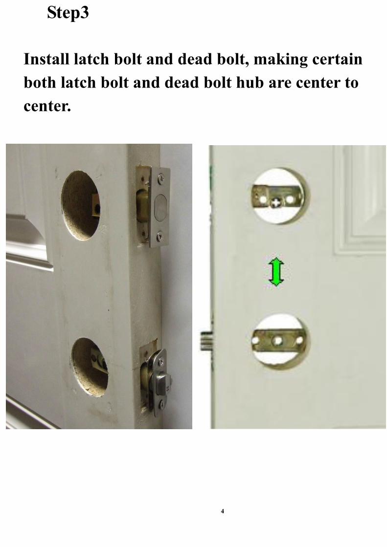
Step3
Install latch bolt and dead bolt, making certain
both latch bolt and dead bolt hub are center to
center.
5
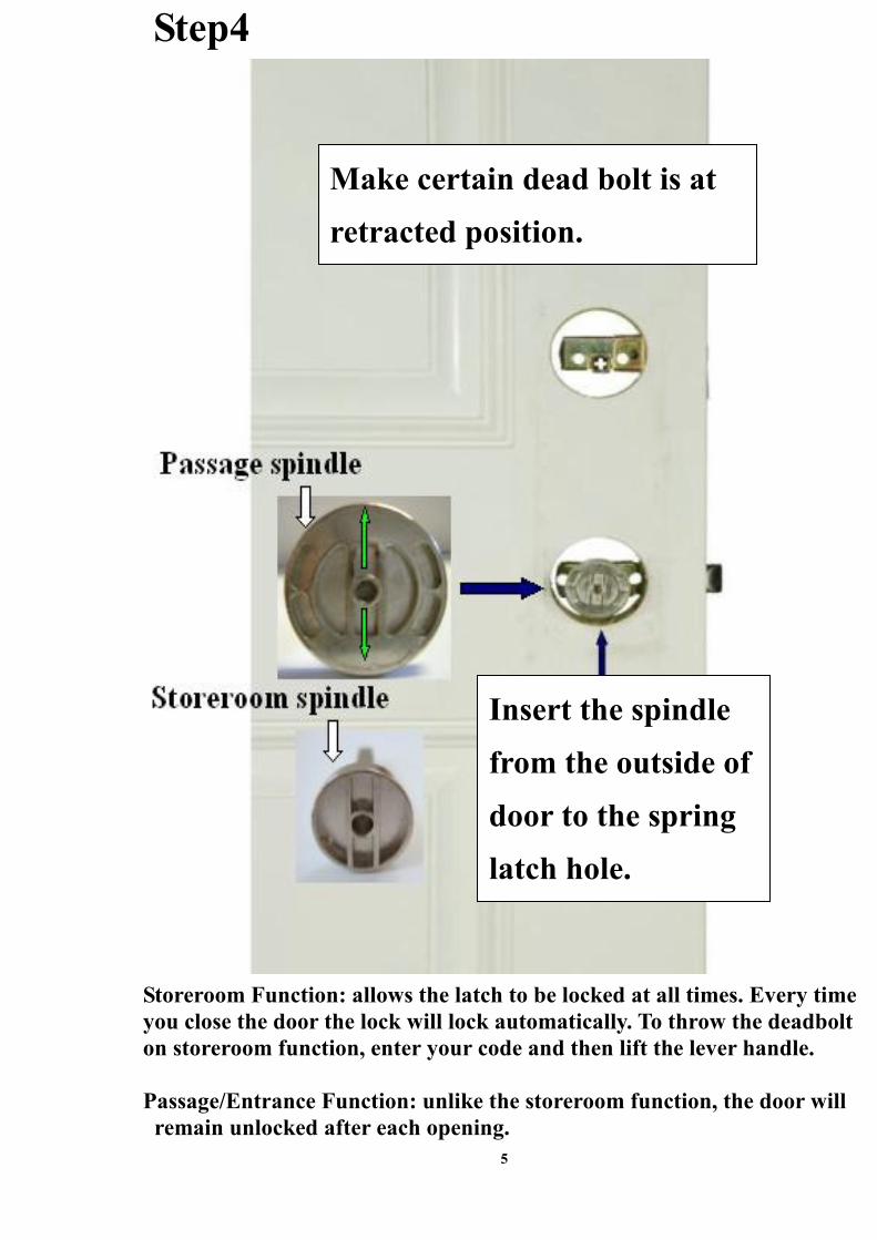
Step4
Storeroom Function: allows the latch to be locked at all times. Every time
you close the door the lock will lock automatically. To throw the deadbolt
on storeroom function, enter your code and then lift the lever handle.
Passage/Entrance Function: unlike the storeroom function, the door will
remain unlocked after each opening.
Insert the spindle
from the outside of
door to the spring
latch hole.
Make certain dead bolt is at
retracted position.

6
Step5
Set the handing
cam to the
correct position.
(To match your
door swing R or
L. From outside,
the door hinges
are on the left
that is left door
swing and so
on.)
R
L
Right door swing
Left door swing

7
Step6
Thread wire harness below
dead bolt chaise (bypass
the posts).

8
Step7
Place the outer lock body to engage with
the spindle in alignment (the cam clutch
smoothly engages with the spindle, align
both inside and outside housings to ensure
proper installation.

9
Step8
Install interior
mechanism
(sandwich plate)
Sandwich plate

10
Step9
Tailpiece
Direction of tailpiece,
vertical (RIGHT
HAND), horizontal
(LEFT HAND), for
door swing
Right door swing
Left door swing

11
Step10
Engage interior
mechanism
through Spindle
hub hole.

12
Step11
Engage tailpiece
through dead
bolt hub.
Correct position for
the wire harness
Wrong position for the wire
harness (that will stop the
movement of tailpiece)
Tailpiece
X

13
Step12
Make certain sandwich plate
screws are tight (this will
prevent shifting of both
outside and inside plates).
Flat head screws must be
tightened otherwise it will
interfere the movement of
dead bolt.
Flat head screws
Round head
screws (longer
than other 4
round head
screws)

14
Step13
Connect with wire harness.
In assembly, make certain wire
harness is located under the
inside housing.
15
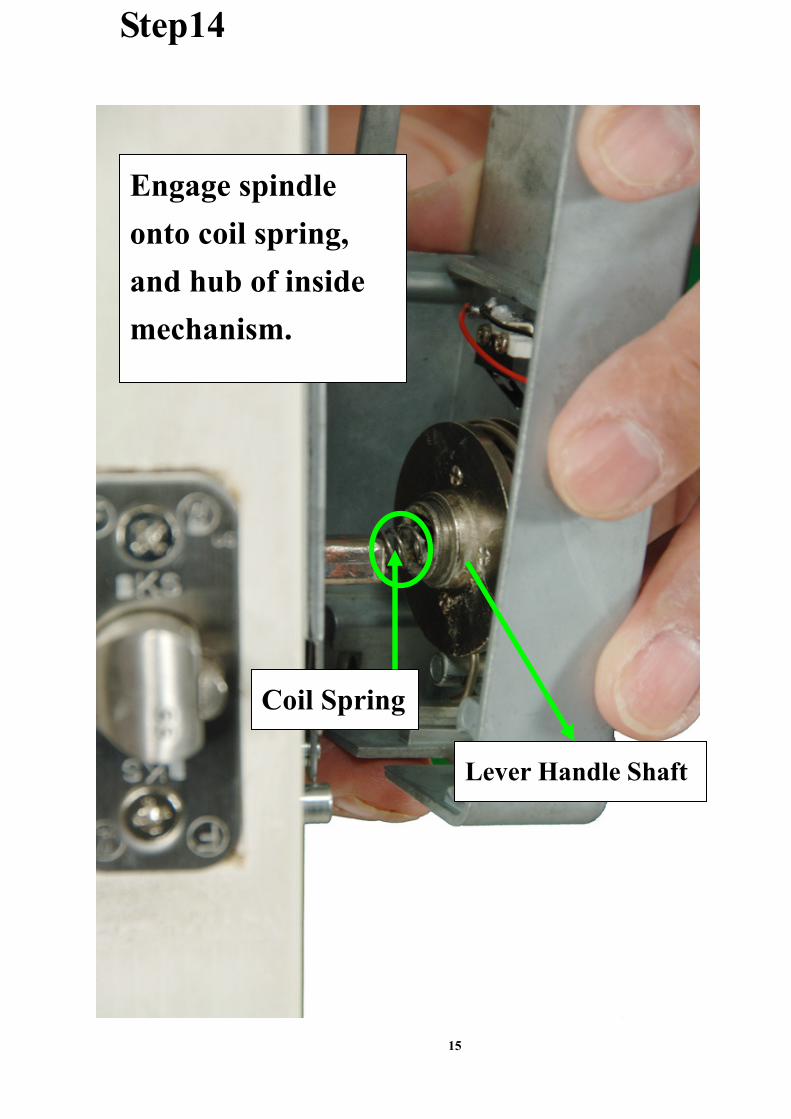
Step14
Engage spindle
onto coil spring,
and hub of inside
mechanism.
Lever Handle Shaft
Coil Spring

16
Step15
Tighten with 4
Round head
screws
(Shorter than
other 2 round
head screws)

17
Step16
Attach inside
escutcheon

18
Step17
Tighten with two 2mm screws on both sides.

19
Step18
Attach nylon washer and lever handle on
inside and outside escutcheon.
20
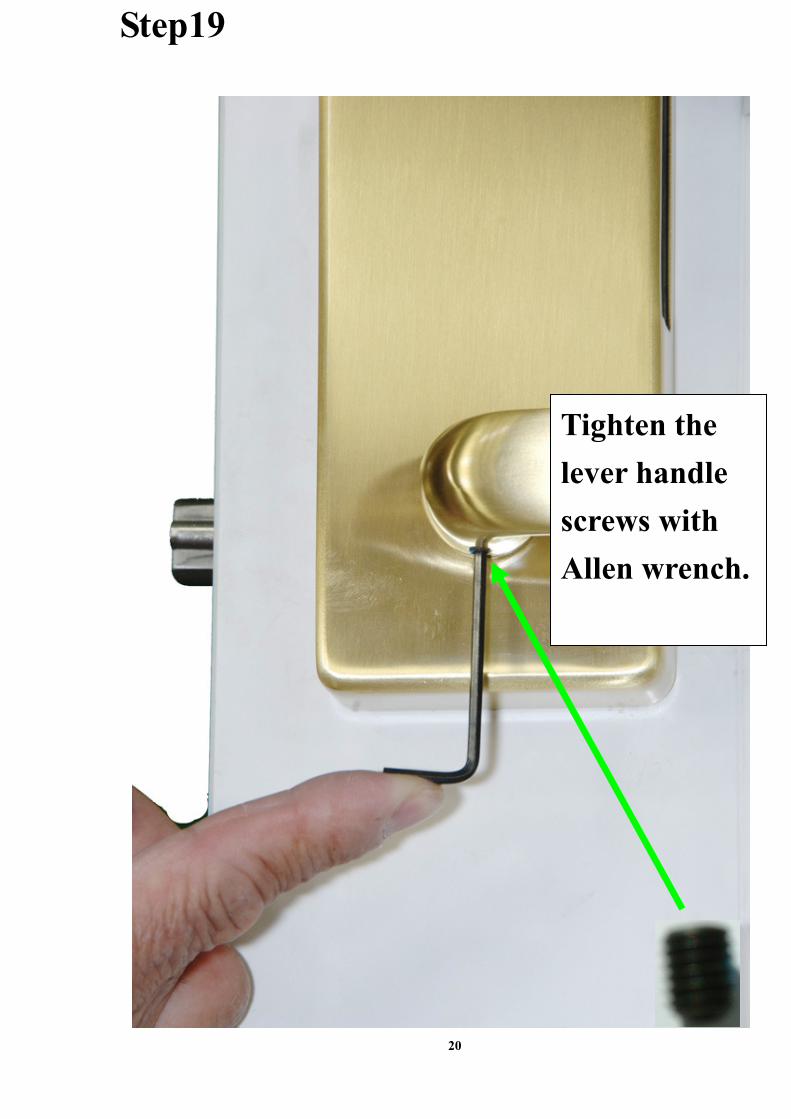
Step19
Tighten the
lever handle
screws with
Allen wrench.

21
Step20
Troubleshooting ● Handing Cam Reversed
Right door swing
Correct positions
Insert battery housing with,
batteries into the inner lock
(make certain batteries are
in the correct direction)

22
Incorrect positions
The lock can be opened from outside without pressing the key fob
● Tail-piece Reversed
Right door swing
Correct positions
Incorrect positions
V V
V x
V V

23
The lock can not be opened or locked from inside or outside
● Tail-piece and Handing Cam Reversed
Right door swing
Correct positions
Incorrect positions
The door swing will be the left swing
Vx
V V
x
x

24
● Please make sure of that the two flat screws are firmly tight to
the two holes on the top of interior mechanism plate otherwise
that will interfere the movement of dead bolt
(Step 12)
● Incorrect positions for spindle hub hole of latch
The lever handles can not be pressed down or lifted up
Correct positions for spindle hub hole of latch
● Incorrect direction of spindle
x V
-x x-
V V

25
The lock can not be opened or locked from outside
Correct direction of spindle
●●●● Final Operation Test
■■■■ Lift Lever Handle from inside or outside to lock Dead Bolt.
Confirm door cannot be opened from outside.
■■■■ WHEN LOCKING DOOR LIFT LEVER HANDLE up till
stop position . If Lever Handle is lifted partially, dead bolt
may not be extended to its full potential
■■■■ Egress exit by pressing down inside Lever Handle.
■■■■ Do not use chemicals or abrasive materials to clean lock.
x
VV
x

26
■■■■ Lock Door from Inner Lock
■■■■ How to set up second security
Lift up lever handle to
lock door
Press down lever handle
to unlock door
Use
push-pin to
Press down
the button
of inner
lock
27
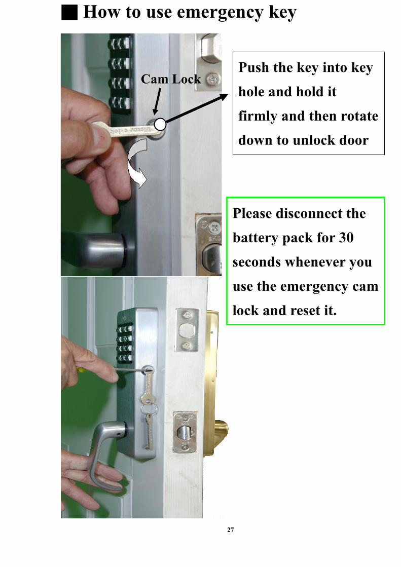
■■■■ How to use emergency key
Push the key into key
hole and hold it
firmly and then rotate
down to unlock door
Cam Lock
Please disconnect the
battery pack for 30
seconds whenever you
use the emergency cam
lock and reset it.

28
Specification and Operation
●●●● Interconnected dead bolt and lever lock.
●●●● Stand alone 4 AA batteries.
●●●● Low battery warning indicator.
●●●● Passage/Entrance or storeroom function at your choice(included in this lock).
●●●● 4 AA batteries not included.
●●●● Grade 2 approved (20 Min). Fire rated.
● Original Master Code is “1234”.
● Master Code can be changed at any time.
● Provides 20 groups for user codes(Master Code is not included).
● The setting of user codes and Master Code is from 4 to 8 digits.
● User codes can be added or deleted at any time.
● Original second security code is “123”(3 digits only).
● Second security code can be changed at any time.
● Second security code is one group only.
● Double Security System, Standard.
● Night burglar alarm.
● Burglar alarm is included in this lock.
● How to lock door
Just lift up lever handle to lock door.
● How to unlock door
( **** →→→→ User Code or Master Code →→→→ #### )
■■■■ Low battery: The LED blinks with orange color 3 times.
● How to change Master Code
( **** →→→→ #### →→→→ 0 →→→→ #### →→→→ Current Master Code →→→→ #### →→→→ New Master Code
→→→→ #### )
Please always remember the Master Code you changed
● How to add user codes
( **** →→→→ #### →→→→ 1 →→→→ #### →→→→ Master Code →→→→ #### →→→→ New User Code →→→→ #### )

29
● How to delete user codes
( **** →→→→ #### →→→→ 2 →→→→ #### →→→→ Master Code →→→→ #### →→→→ User Code →→→→ #### )
●●●● How to delete all user codes
( **** →→→→ #### →→→→ 3 →→→→ #### →→→→ Master Code →→→→ #### )
●●●● How to change second security code
( **** →→→→ #### →→→→ 4 →→→→ #### →→→→ Master Code →→→→ #### →→→→ New Second Security Code
→→→→ #### )
● How to set up Second Security System
From outer lock
( **** →→→→ Current Second Security Code →→→→ #### )
From inner lock
Press the black button of inner lock (the red LED of inside lock blinks with red color and
buzz 3 times at the same time).
● How to remove Second Security System:
From outer lock only ( **** →→→→ Current Second Security Code →→→→ #### )
● Burglar Alarm System:
◆◆◆◆ Set up Second Security System from outer lock already:
Burglar alarm immediately sounds when someone opens door from inside.
◆◆◆◆ Set up Second Security System from inner lock already:
Burglar alarm will sound in 20 seconds when someone opens door from inside (the red
LED keeps blinking).
30
How to stop: Remove second security from outer lock in 20 seconds (press second security
code from outer lock) otherwise release batteries for 30 seconds.
◆◆◆◆ If you continuously press any wrong entrance codes 3 times, burglar alarm will sound
for 2 minutes, and not allowed to press any entrance codes. After that, the LED blinks
with green and red color 10 times when you press correct entrance codes.
※※※※ How to stop the sounds of Burglar Alarm System: Release batteries for 30 seconds.