kompetenz in messtechnik und kundenbetreuung fileinstruction manual fh 10– 500 ext thank you for...
TRANSCRIPT

Measuring system
Measuring range [Max]: 200 N
Overload protection (of [Max]): 150 %
Precision (of [Max]): 0,005
Readout [d]: 0,100 N
Test frequency: 2000 Hz
Display
Display digit height: 1 cm
Functions
Data hold function: yes
Function to set limits: yes
Obtaining average: yes
Peak function: yes
Statistical function: yes
Environmental conditions
Maximum operating temperature: 40 OC
Minimum ambient temperature: 10 OC
Power supply
Charging time: 1 h
Input voltage: 100 V - 240 V
n/a: CH EURO
n/a: Mains adapter external
Power supply
Operating time (Backlight off): 12 h
Service
DAkkS Calibration certificate 963-261
(Pressure):
DAkkS Calibration certificate 963-161
(Tensile):
DAkkS Calibration certificate 963-361
(Tensile/Pressure):
ISO calibration certificate: 961-361
ISO Calibration certificate (Pressure): 961-261
ISO Calibration certificate (Tensile): 961-161
ISO Calibration certificate (Ten- 961-361
sile/Pressure):
Category
Brand: Sauter
Category: Force gauges
Product Group: Electronic force-measuring
device
Packaging & shipping
Delivery: 24 h
Dimensions packaging (WxDxH): 325 x 185 x 165 mm
Gross weight: 2 kg
Net weight: 1,300 kg
Shipping method: Parcel service
UN number: 3496
Construction
Cable length: 2,500 m
Dimensions of display device
(WxDxH):
230 x 66 x 36 mm
Overall dimensions mounted
(WxDxH):
230 x 66 x 36 mm
1
X-SENSORS GmbH l Steinbrechstr. 9, 71106 – Magstadt, Deutschland l Tel: +49 7159/49697-0 l [email protected] l www.sensorshop.com
FH-EXT X-SENSORS GmbH
Magstadt, Deutschland l Tel: +49 7159/49697-0 [email protected] l www.sensorshop.com Kompetenz in Messtechnik und Kundenbetreuung

Instruction Manual
FH 10– 500 EXT
Thank you for buying a force gauge. We hope you are
pleased with your high quality force gauge with its big
functional range. If you have any queries, wishes or helpful
suggestions, do not hesitate to call our service number.
„Sensor Outside“ means the cell is outside the body.
1. Included in Delivery
- FH, incl. rechargeable battery
- Carrying Case
- Charger
- Standard attachments, 5 pieces. M3x 8 screws
Dimensions in mm for the instruments
FH 10 EXT up to FH 500 EXT:
Set
Pilot lamp
LCD
Force sensor
RS 232 port
Sensor
Outside
B
L
FH_10-500-BA-e-1213 1
X-SENSORS GmbH l Steinbrechstr. 9, 71106 – Magstadt, Deutschland l Tel: +49 7159/49697-0 l [email protected] l www.sensorshop.com
FH-EXT X-SENSORS GmbH
Magstadt, Deutschland l Tel: +49 7159/49697-0 [email protected] l www.sensorshop.com Kompetenz in Messtechnik und Kundenbetreuung

Instruction Manual
FH 10– 500 EXT
Dimensions of the sensor L x B x H:
74 x 50 x 22 mm
Cable length between display and sensor: 2 m
Important annotation:
By pressing the RESET key (on the right side of housing,
see illustration on the left), individual settings and
memorised values can be re-set or erased, in example for
a new start of the instrument after an operating error.
2. Working Conditions
10°C to 30°C / 15% up to 80% humidity
3. Electrical Power Supply
Either by recharchable battery or current power supply
Current power supply:
are charged
- Connection by power adapter
- Rechargeable batteries
simultaneously
Rechargeable battery pack for mobile applications:
- Type: Ni 8.4V / 600 mAh
- Charging time: approx. 1 hour
4. Technical Data
- Accuracy: ± 0,5 % of capacity
- Data Sampling Rate: 2.000 Hz
- Weight: 640 g
Operation 5.
Display
(1) Measuring Result
(2) Measuring Units
(3) Activation of PRINT Function
(4) Indication of power charging status
PEAK or AUTO-PEAK Mode
(5) Average value of stored peak values
(6) Force direction
(7) Occupancy of storing spaces
(8) AVERAGE- or Saving Mode
External sensor with accessories for compression tests
Operating keys
ON / OFF:
ON / OFF key
(For ON, press 1 sec.)
UNIT:
- Press short:
- Press for 2 sec.:
Select unit:
N, kg or lb
Display return
ZERO:
Three functions:
- Zeros the measuring result (Tara function)
- Cleans the peak value (in Peak mode)
- Saves a setting (in SET mode
100 mm
H
FH_10-500-BA-e-1213 2
X-SENSORS GmbH l Steinbrechstr. 9, 71106 – Magstadt, Deutschland l Tel: +49 7159/49697-0 l [email protected] l www.sensorshop.com
FH-EXT X-SENSORS GmbH
Magstadt, Deutschland l Tel: +49 7159/49697-0 [email protected] l www.sensorshop.com Kompetenz in Messtechnik und Kundenbetreuung
Instruction Manual
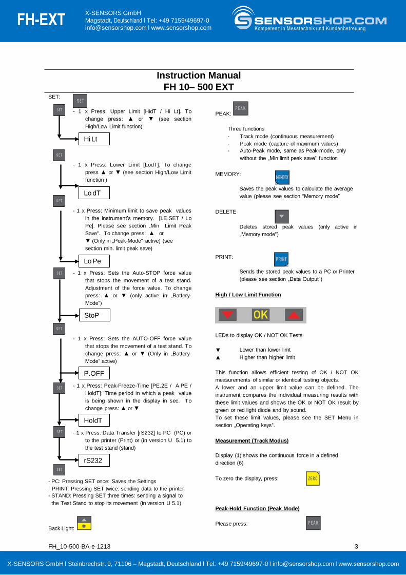
FH 10– 500 EXT SET:
- 1 x Press: Upper Limit [HidT / Hi Lt]. To
change press: ▲ or ▼ (see section
High/Low Limit function)
- 1 x Press: Lower Limit [LodT]. To change
press ▲ or ▼ (see section High/Low Limit
function )
- 1 x Press: Minimum limit to save peak values
in the instrument’s memory. [LE.SET / Lo
Pe]. Please see section „Min Limit Peak
Save“. To change press: ▲ or
▼ (Only in „Peak-Mode“ active) (see
section min. limit peak save)
- 1 x Press: Sets the Auto-STOP force value
that stops the movement of a test stand.
Adjustment of the force value. To change
press: ▲ or ▼ (only active in „Battery-
Mode“)
- 1 x Press: Sets the AUTO-OFF force value
that stops the movement of a test stand. To
change press: ▲ or ▼ (Only in „Battery-
Mode“ active)
- 1 x Press: Peak-Freeze-Time [PE.2E / A.PE /
HoldT]: Time period in which a peak value
is being shown in the display in sec. To
change press: ▲ or ▼
- 1 x Press: Data Transfer [rS232] to PC (PC) or
to the printer (Print) or (in version U 5.1) to
the test stand (stand)
- PC: Pressing SET once: Saves the Settings
- PRINT: Pressing SET twice: sending data to the printer
- STAND: Pressing SET three times: sending a signal to
the Test Stand to stop its movement (in version U 5.1)
Back Light:
PEAK:
Three functions
- Track mode (continuous measurement)
- Peak mode (capture of maximum values)
- Auto-Peak mode, same as Peak-mode, only
without the „Min limit peak save“ function
MEMORY:
Saves the peak values to calculate the average
value (please see section “Memory mode”
DELETE
Deletes stored peak values (only active in
„Memory mode“)
PRINT:
Sends the stored peak values to a PC or Printer
(please see section „Data Output”)
High / Low Limit Function
LEDs to display OK / NOT OK Tests
▼
▲
Lower than lower limt
Higher than higher limit
This function allows efficient testing of OK / NOT OK
measurements of similar or identical testing objects.
A lower and an upper limit value can be defined. The
instrument compares the individual measuring results with
these limit values and shows the OK or NOT OK result by
green or red light diode and by sound.
To set these limit values, please see the SET Menu in
section „Operating keys“.
Measurement (Track Modus)
Display (1) shows the continuous force in a defined
direction (6)
To zero the display, press:
Peak-Hold Function (Peak Mode)
Please press:
Hi Lt
Lo dT
Lo Pe
P.OFF
HoldT
rS232
StoP
FH_10-500-BA-e-1213 3
X-SENSORS GmbH l Steinbrechstr. 9, 71106 – Magstadt, Deutschland l Tel: +49 7159/49697-0 l [email protected] l www.sensorshop.com
FH-EXT X-SENSORS GmbH
Magstadt, Deutschland l Tel: +49 7159/49697-0 [email protected] l www.sensorshop.com Kompetenz in Messtechnik und Kundenbetreuung

Instruction Manual
FH 10– 500 EXT
This function allows to eliminate unwanted „Pre-Peak
values“ that are lower than the main peak value (Fp). The
“Min limit peak save” value (Fo) takes care, that these
“Pre-Peak values” are not saved.
The „Min limit peak save“ function is only possible in Peak-
Mode.
To set this Min limit value, please see the SET Menu in
section „Operating keys“.
Memory mode and average value (from up to 10 peak
values)
Saving peak values in the instrument
Activating the „AUTO PEAK Function“ by PEAK key
Deactivating the „Average Function“ by MEMORY key
Now, all peak values are stored automatically in the instrument
To browse through the stored values, please use the ▲ or ▼ keys. (The values will be shown in the upper display segment)
By pressing the MEMORY key, the average value of the stored peak values can be shown (in the upper
display segment)
To delete every stored value, press the▼-key in the
AVERAGE-Mode
6. Configuration of RS 232
SUB-D 9pm
Auto-Peak-Hold-Function(Auto-Peak Mode)
Please press:
Pin Signal Illustration
2 TxD Output signal
3 RxD Input signal
5 GND Ground
6 +1.6 to + 2 V Over upper limit
7 +1.6 to + 2 V Lower than lower limit
8 +1.6 to + 2 V OK Min. limit peak save
6.1 Output Protocol
RS-232 Parameter:
Baud rate:
Data-Bit:
Parity:
Stop-Bit:
9600
8
none
1
The measured value is requested by the PC by the ASCII
Sign “9”.
The measured value that comes from the instrument has
this format:
e.g. 0011.70 means -11,70 Newton, if
Newton is the selected unit
||-----|
| | > the other 6 places describe the
measured value as ASCII-Signs
| > the first place desribes the
direction of the force (0 = minus = Pressure;
1 = plus = Tension)
or: 1021.15 means +21,15 N (Tension)
| > the first place describes the
direction of the force (0 = minus = Pressure;
1 = plus = Tension)
or: 1021.15 means +21,15 N (Tension)
7. Warning
Intended use
The instrument you have acquired serves to determine the
measuring value of the material to be measured. It is
intended to be used as a “non-automatic“ instrument, i.e.
the material to be measured is manually and carefully
attached at the instrument. The measuring value can be
read off after a stable measuring value has been obtained.
Inappropriate use
Do not use the instrument for dynamic measuring. In the
event that small quantities are removed or added to the
FH_10-500-BA-e-1213 4
X-SENSORS GmbH l Steinbrechstr. 9, 71106 – Magstadt, Deutschland l Tel: +49 7159/49697-0 l [email protected] l www.sensorshop.com
FH-EXT X-SENSORS GmbH
Magstadt, Deutschland l Tel: +49 7159/49697-0 [email protected] l www.sensorshop.com Kompetenz in Messtechnik und Kundenbetreuung

Instruction Manual
FH 10– 500 EXT material to be measured, incorrect measuring results can
be displayed due to the “stability compensation“ in the
instrument. (Example: Slow draining
off of liquid from a container suspended from the
instrument). Do not attach a continuous load. This can
damage the measuring
unit as well as the parts, relevant to safety.
Prevent jolts, torsion and oscillation (e.g. by appending
slopingly) of all kinds. Be sure to prevent overloading the
instrument in excess of the stated maximum load (max.),
minus any tare weight that may possibly exist. This could
damage the instrument (risk of breakage).
Important:
•Always make sure that there are no people or materials
below the load that could be injured or damaged!
•The instrument is not suitable for measuring people. Do
not use as baby scales!
•The instrument does not comply with the medical product
law (MPG).
Never operate the instrument in hazardous locations. The
series design is not explosion-proof. Structural alterations
may not be
effected to the instrument. This can lead to incorrect
measuring results, faults concerning safety regulations as
well as to destruction
of the instrument. The instrument may only be used in
compliance with the described guidelines. Varying areas of
application/
planned use must be approved by in writing.
FH_10-500-BA-e-1213 5
Guarantee
The guarantee is not valid following
•Non-observation of our guidelines in the operating
instructions
• Alteration to or opening of the device
•Mechanical damage and damage caused by media,
liquids
• Natural wear and tear
• Inappropriate erection or electric installation
• overloading of the measuring equipment
Monitoring the test substances
The metrology features of the instrument and any possible
available adjusting weight must be checked at regular
intervals within the scope of quality assurance. For this
purpose, the answerable user must define a suitable
interval as well as the nature and scope of this check.
Information is available on the home page
(www.SensorShop.com) with regard to the monitoring of
instrument test substances and the test weights required
for this. Test weights and instruments can be adjusted
quickly and at a reasonable price in KERN’s accredited
DKD calibration laboratory (return to national normal).
Fundamental safety information
Do not use the hanging instrument to transport loads.
Prevent jolts, torsion and oscillation (e.g. by appending
slopingly) of all kinds.
Never use the hanging instrument over the maximum
permitted weight (!! Danger of breaking!!).
Always make sure that there are no living beings or
materials below the load that could be injured or damaged.
The hanging electronic instruments from the instrument
are only suitable for hand-held use or use in a test stand.
They are not suitable for hanging from a mechanical hook,
e.g. a crane hook.
Observe the information in the operating instructions
please read the operating instructions carefully before
erecting
and commissioning, even if you already have experience
with instruments.
Staff training
The device may only be operated and looked after by
trained members of staff.
Major display deviations (incorrect measuring results) are
possible if electromagnetic fields occur as well as due to
static
charging and instable power supply. It is then necessary to
change the location.
Unpacking
Carefully remove the instrument from its packaging,
remove the plastic wrapping and position the instrument in
its intended working location.
X-SENSORS GmbH l Steinbrechstr. 9, 71106 – Magstadt, Deutschland l Tel: +49 7159/49697-0 l [email protected] l www.sensorshop.com
FH-EXT X-SENSORS GmbH
Magstadt, Deutschland l Tel: +49 7159/49697-0 [email protected] l www.sensorshop.com Kompetenz in Messtechnik und Kundenbetreuung
Instruction Manual
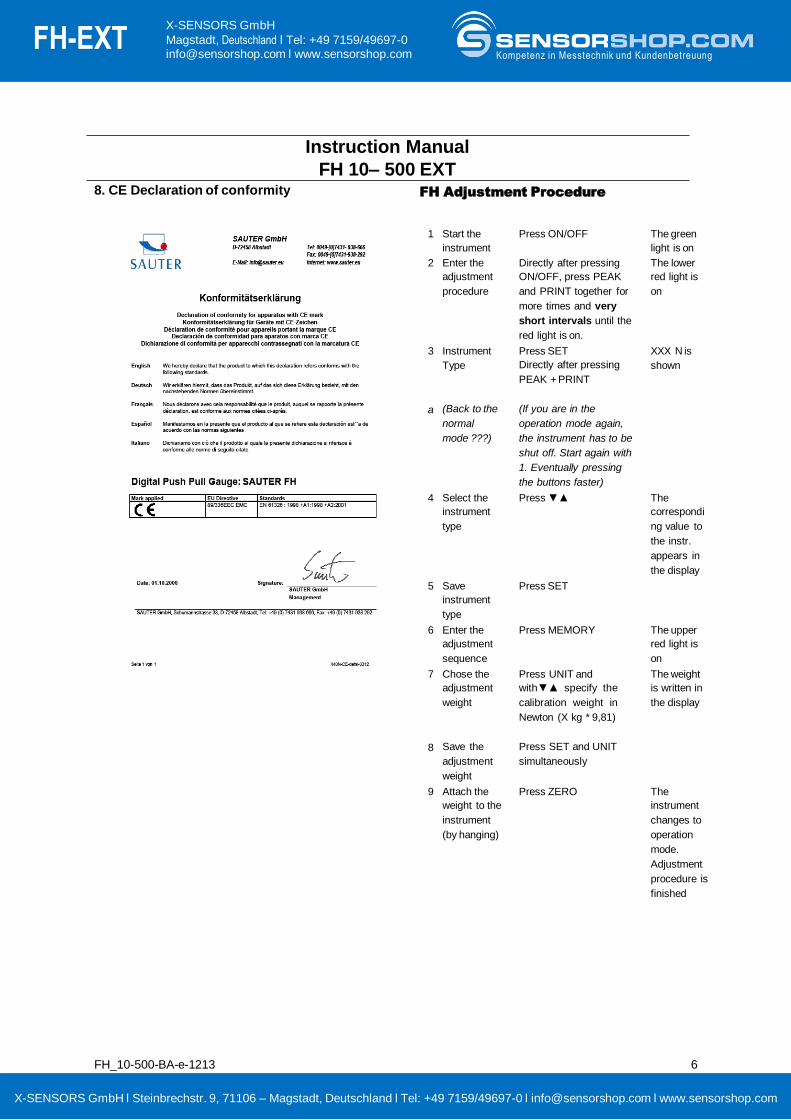
FH 10– 500 EXT 8. CE Declaration of conformity FH Adjustment Procedure
FH_10-500-BA-e-1213 6
1 Start the
instrument
Press ON/OFF The green
light is on
2 Enter the
adjustment
procedure
Directly after pressing
ON/OFF, press PEAK
and PRINT together for
more times and very
short intervals until the
red light is on.
The lower
red light is
on
3 Instrument
Type
Press SET
Directly after pressing
PEAK + PRINT
XXX N is
shown
a (Back to the
normal
mode ???)
(If you are in the
operation mode again,
the instrument has to be
shut off. Start again with
1. Eventually pressing
the buttons faster)
4 Select the
instrument
type
Press ▼▲ The
correspondi
ng value to
the instr.
appears in
the display
5 Save
instrument
type
Press SET
6 Enter the
adjustment
sequence
Press MEMORY The upper
red light is
on
7 Chose the
adjustment
weight
Press UNIT and
with▼▲ specify the
calibration weight in
Newton (X kg * 9,81)
The weight
is written in
the display
8 Save the
adjustment
weight
Press SET and UNIT
simultaneously
9 Attach the
weight to the
instrument
(by hanging)
Press ZERO The
instrument
changes to
operation
mode.
Adjustment
procedure is
finished
X-SENSORS GmbH l Steinbrechstr. 9, 71106 – Magstadt, Deutschland l Tel: +49 7159/49697-0 l [email protected] l www.sensorshop.com
FH-EXT X-SENSORS GmbH
Magstadt, Deutschland l Tel: +49 7159/49697-0 [email protected] l www.sensorshop.com Kompetenz in Messtechnik und Kundenbetreuung

FH Schnittstellenbeschreibung
17.05.2016 FH-SCHNITTSTELLEN BESCHREIBUNG DP
Senden vom PC Gerät
ASCⅡ Dezimal Hex
2 50 32 Anzeige auf „Null“ stellen
3 51 33 Einheit umstellen auf "KN"
4 52 34 Einheit umstellen auf "TF"
5 53 35 Einheit umstellen auf "KLBF"
6 54 36 Schaltet Gerät in den Track Modus
7 55 37 Schaltet Gerät in den Peak Modus
9 57 39 Gerät sendet aktuellen wert an den PC
Sendeformat
1. bei der Einheit kN sieht das Daten Byte folgender maßen aus:
bit 1 bit 2 bit 3 bit 4 bit 5 bit 6 bit 7
Kraft-
richtung
data 1
data 2
Dezimal
punkt
data 3
data 4
data 5
Bit 1 Kraftrichtung
1: Kraftrichtung “Zug”
0: Kraftrichtung “Druck”
Wenn das Gerät 0,005 kN in “Zugrichtung misst sieht
das Datenbyte folgender maßen aus:
bit 1 bit 2 bit 3 bit 4 bit 5 bit 6 bit 7
1 0 0 . 0 0 5
Wenn das Gerät 0,005 kN in “Druckrichtung misst sieht das Datenbyte folgender maßen
aus:
bit 1 bit 2 bit 3 bit 4 bit 5 bit 6 bit 7
0 0 0 . 0 0 5
- Baudrate: 9600 - Daten-Bit: 8 - Parität: keine - Stop-Bit: 1
Beispiel:
Der Messwert wird durch das ASCII-Zeichen „9“ angefordert.
Der zurückgelieferte Messwert sieht folgendermaßen aus:
bedeutet -11,70 Newton, wenn Newton als Einheit eingestellt ist z.B. 0011.70
||-----|
| | >
| >
die restlichen 6 Stellen beschreiben den Messwert als ASCII-Zeichenkette
erstes Zeichen beschreibt das Vorzeichen (0 = minus = Druck; 1 = plus = Zug)
oder: 1021.15 bedeutet +21,15 N (Zugkraft)
X-SENSORS GmbH l Steinbrechstr. 9, 71106 – Magstadt, Deutschland l Tel: +49 7159/49697-0 l [email protected] l www.sensorshop.com
FH-EXT X-SENSORS GmbH
Magstadt, Deutschland l Tel: +49 7159/49697-0 [email protected] l www.sensorshop.com Kompetenz in Messtechnik und Kundenbetreuung

FH Data Connection protocol
17.05.2016 FH-SCHNITTSTELLEN BESCHREIBUNG DP
Senden vom PC Device
ASCⅡ decimal hex
3 50 32 Set the unit to “zero”
3 51 33 make the unit as "KN"
4 52 34 make the unit as "TF"
5 53 35 make the unit as "KLBF"
6 54 36 make the gauge on the tracking mode
7 55 37 make the gauge on the peak mode
9 57 39 send the value data to pc
format of sending
1. when the unit is " KN", the format sending as:
bit 1 bit 2 bit 3 bit 4 bit 5 bit 6 bit 7
bit of
force
direction
data 1
data 2
point
data 3
data 4
data 5
bit of force direction
1: force direction is pull 0:
force direction is press
if the pull force is 0.005KN, and the unit is "KN" the
format of sending is:
bit 1 bit 2 bit 3 bit 4 bit 5 bit 6 bit 7
1 0 0 . 0 0 5
if the pressure is 0.005KN, and the unit is "KN"
the format of sending is:
bit 1 bit 2 bit 3 bit 4 bit 5 bit 6 bit 7
0 0 0 . 0 0 5
- Baudrate: 9600 - Data-Bit: 8 - Parity: none - Stop-Bit: 1
Example: The measured value requested through sending ASCII-sign „9“ from the PC to the force gauge
The requested data looks like:
z.B. 0011.70 means -11.70 N if the force gauge is set to unit Newton
||-----|
| | > the other 6 digits are the measured value in ASCII
| > the first sign in the byte is the pre sign (0 = minus = comprehension;
1 = plus = Tension)
or: 1021.15 means +21,15 N
X-SENSORS GmbH l Steinbrechstr. 9, 71106 – Magstadt, Deutschland l Tel: +49 7159/49697-0 l [email protected] l www.sensorshop.com
FH-EXT X-SENSORS GmbH
Magstadt, Deutschland l Tel: +49 7159/49697-0 [email protected] l www.sensorshop.com Kompetenz in Messtechnik und Kundenbetreuung
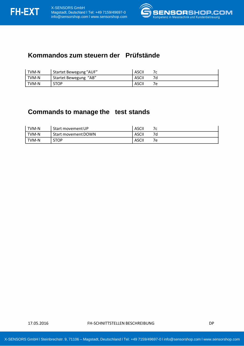
Kommandos zum steuern der Prüfstände
17.05.2016 FH-SCHNITTSTELLEN BESCHREIBUNG DP
Commands to manage the test stands
TVM-N Startet Bewegung “AUF” ASCII 7c
TVM-N Startet Bewegung “AB” ASCII 7d
TVM-N STOP ASCII 7e
TVM-N Start movement UP ASCII 7c
TVM-N Start movement DOWN ASCII 7d
TVM-N STOP ASCII 7e
X-SENSORS GmbH l Steinbrechstr. 9, 71106 – Magstadt, Deutschland l Tel: +49 7159/49697-0 l [email protected] l www.sensorshop.com
FH-EXT X-SENSORS GmbH
Magstadt, Deutschland l Tel: +49 7159/49697-0 [email protected] l www.sensorshop.com Kompetenz in Messtechnik und Kundenbetreuung

FH_10-500_EXT-dimensions 1
FH 10 EXT to FH 500 EXT Dimensions
Dimensions of the sensor
L x B x H:
76 x 65 x 22 mm
Cable length: 2 m
External Sensor with accessories for push tests.
100 mm
H
B
L
X-SENSORS GmbH l Steinbrechstr. 9, 71106 – Magstadt, Deutschland l Tel: +49 7159/49697-0 l [email protected] l www.sensorshop.com
FH-EXT X-SENSORS GmbH
Magstadt, Deutschland l Tel: +49 7159/49697-0 [email protected] l www.sensorshop.com Kompetenz in Messtechnik und Kundenbetreuung

Dimensionen FH externe Kraftmesszellen
FH-ZB-d-1410 1
Höchstlast HxLxW T Kabellänge
1 kN 76,2x50,8x19,0 mm M12 x 1,75
Ca. 3m
2 kN 76,2x50,8x19,0 mm M12 x 1,75
5 kN 76,2x50,8x28,2 mm M12 x 1,75
10 kN 76,2x50,8x28,2 mm M12 x 1,75
20 kN 76,2x50,8x28,2 mm M12 x 1,75
50 kN 108x76,2x25,4 mm M18 x 1,5
100 kN 177,8x125,0x50,8 mm M30 x 2,0
X-SENSORS GmbH l Steinbrechstr. 9, 71106 – Magstadt, Deutschland l Tel: +49 7159/49697-0 l [email protected] l www.sensorshop.com
FH-EXT X-SENSORS GmbH
Magstadt, Deutschland l Tel: +49 7159/49697-0 [email protected] l www.sensorshop.com Kompetenz in Messtechnik und Kundenbetreuung

Dimension FH external load cells
2 FH-ZB-d-1410
Maximum Load HxLxW T Cable length
1 kN 76,2x50,8x19,0 mm M12 x 1,75
Ca. 3m
2 kN 76,2x50,8x19,0 mm M12 x 1,75
5 kN 76,2x50,8x28,2 mm M12 x 1,75
10 kN 76,2x50,8x28,2 mm M12 x 1,75
20 kN 76,2x50,8x28,2 mm M12 x 1,75
50 kN 108x76,2x25,4 mm M18 x 1,5
100 kN 177,8x125,0x50,8 mm M30 x 2,0
X-SENSORS GmbH l Steinbrechstr. 9, 71106 – Magstadt, Deutschland l Tel: +49 7159/49697-0 l [email protected] l www.sensorshop.com
FH-EXT X-SENSORS GmbH
Magstadt, Deutschland l Tel: +49 7159/49697-0 [email protected] l www.sensorshop.com Kompetenz in Messtechnik und Kundenbetreuung

FH-ZB-d-1410 1
Dimensionen FH externe Kraftmesszellen FH 10 EXT bis FH 500 EXT
Abmessungen
L x B x H:
76 x 65 x 22 mm
G: Gewinde M6
Kabellänge: 2 m
Externer Sensor mit Zubehör für Drucktests.
100 mm
L
B G
G
H
X-SENSORS GmbH l Steinbrechstr. 9, 71106 – Magstadt, Deutschland l Tel: +49 7159/49697-0 l [email protected] l www.sensorshop.com
FH-EXT X-SENSORS GmbH
Magstadt, Deutschland l Tel: +49 7159/49697-0 [email protected] l www.sensorshop.com Kompetenz in Messtechnik und Kundenbetreuung
2 FH-ZB-d-1410
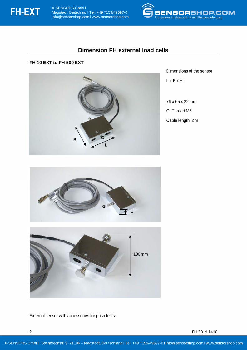
Dimension FH external load cells FH 10 EXT to FH 500 EXT
Dimensions of the sensor
L x B x H:
76 x 65 x 22 mm
G: Thread M6
Cable length: 2 m
External sensor with accessories for push tests.
100 mm
L
B G
G
H
X-SENSORS GmbH l Steinbrechstr. 9, 71106 – Magstadt, Deutschland l Tel: +49 7159/49697-0 l [email protected] l www.sensorshop.com
FH-EXT X-SENSORS GmbH
Magstadt, Deutschland l Tel: +49 7159/49697-0 [email protected] l www.sensorshop.com Kompetenz in Messtechnik und Kundenbetreuung