komguide – technical manual komguide – technical manual · zahranco, engineering trade 15, ali...
TRANSCRIPT

w w w . k o m e t g r o u p . c o m
ZAHRANCO, ENGINEERING TRADE15, Ali Amer Str. · 6th SectorNasr City · Cairo, EgyptTel. +20-2-2 75 43 46Fax +20-2-2 75 41 83Telex 2 10 57 YAZCO UN
VORTEX S.R.L.Pedro Morán 858Lomas del MiradorBuenos AiresTel. +54-(11) 46 53 01 25Fax +54-(11) 44 88 60 [email protected]
Rosler International PTY Ltd.P.O. BOX 696, 12 The NookBayswater, Vic. 3153Tel. +61-3-97 38 08 89Fax +61-3-97 38 08 87
Komet do Brasil Ltda.Rua Brasileira, 43907043-010 Guarulhos - São PauloTel. +55(0)11.2423-5502Fax +55(0)[email protected]
KOMET GROUP Precision Tools (Taicang) Co., Ltd.(Headquarter Asia Pacific)No. 5 Schaeffler RoadTaicang, Jiangsu Province, 215400Tel. +86(0)512.535757-58Fax +86(0)[email protected]
KOMET Precision Tools India Pvt. Ltd.16J, Attibele Industrial AreaBANGALORE - 562 107Tel. +91-80-2807 8000Fax +91-80-2807 [email protected]
PT Somagede Perkasa Kompleks Griya Inti SentosaJalan Griya Agung No: 3Sunter Agung - Jakarta 14350Tel. +62-21-6 41 07 30Fax +62-21-6 40 15 [email protected]
SHIVEH TOLID Co. LTD.# 270, West Dr. Fatemi Ave.Post Code : 14186TehranTel. +98 21 6 691 7 691Fax +98 21 6 691 7 [email protected]
ARNOLD TRADING Co., Ltd.P.O.B. 201806 Hamachtesh St.Ind. Area, Holon 58810Tel. +9 72-3-5 58 13 13Fax +9 72-3-5 58 13 17
KOMET GROUP KK# 180-00061-22-2 Naka-cho Musashino-shiTokyo Japan Grand Preo Musashino 203Tel. +81(0)422 50 0682Fax +81(0)422 50 [email protected]
KOMET of CANADATooling Solutions ULC250 Harry Walker Parkway NUnit 6B, Newmarket,Ontario, L3Y 7B4Tel. +1 (905) 954-0466Fax +1 (905) [email protected]
KOMET GROUP Precision ToolsKorea Co.,Ltd.#201, Lotte IT Castle-2, 550-1,Gasan-dong,Geumcheon-gu, Seoul, 153-768Tel. +82(0)2.2082.6300Fax +82(0)[email protected]
GP System (Malaysia) Sdn Bhd19-1, Jalan Kenari 7Bandar Puchong Jaya 47100 Puchong, SelangorTel. +60-3-807 59160Fax +60-3-807 [email protected]
KOMET de México S. de R. L. de C.VAcceso 1 Nave 8 No. 116 Fraccionamiento Industrial La Montaña Querétaro, Qro. C.P 76150 MéxicoTel. +52 442 2109020Fax +52 442 [email protected]
Coulson Carbide LimitedDouble J Centre, 24 Gum Road,Henderson Valley, HendersonP.O.Box 21-228, HendersonAuckland Tel. +64-9-8 38 50 61Fax +64-9-8 37 62 86
GP System (Singapore) Pte. Ltd.No. 51, Bukit Batok Crescent#04-04/05 Unity CentreSingapore 658077Tel. +65-68 61 26 63Fax +65-68 61 35 [email protected]
MULTITRADE DISTRIBUTORSP.O. Box 3511Kempton Park1620Tel. +27-11-453-8034Fax +27-11-453-9696
Hung Chih Ltd., Co.No. 37, Chung Cheng RoadTainan, Taiwan, R.O.C.Tel. +8 86-6-2 25 22 16Fax +8 86-6-2 20 59 [email protected]
PERFECT TOOL Co., Ltd.64/298Moo 3 Karnchanapisek Rd..Bakurad BagbuathongNothaburi 11110Tel. +66 2594 4562Fax +66 2594 [email protected]
KOMET of America, Inc.2050 Mitchell Blvd.SchaumburgIL 60193-4544Tel. +1 (8 47) 9 23 / 84 00 +1 (8 47) 9 23 / 84 80Fax +1 (8 00) 8 65 / 66 [email protected]
TINH HA Trading & Service Co., Ltd.Add: 12th Floor, Zodiac Building, Duy Tan Street, Dich Vong Ward,Cau Giay District, Hanoi, VietnamTel. +84 4 62851631Fax +84 4 [email protected]
KOMET GROUP GmbHZeppelinstraße 374354 BesigheimGERMANYTel. +49 7143 3730Fax +49 7143 [email protected]
KOMET GROUP GmbHRuppmannstraße 3270565 Stuttgart / VaihingenGERMANYTel. +49 711 788910Fax +49 711 [email protected]
399 01 099 00-2T-01/14 Printed in Germany www.wachter.de© 2014 KOMET GROUP GmbHWe reserve the right to make modifications.
Precision has a name
Precision and qualitiy do not allow any compromises
in universal cutting operations.
KOMET GROUP is a leading system supplier going
global for precision tools and offers individual
problem solvings and innovative top engineering.
This guarantees consistent quality and economic
efficiency.
Precision tools for drilling into the solid, boring,
fine boring, reaming, milling, turning, threading
and for special applications – this is represented
by the name of KOMET GROUP.
Ko
mG
uid
e –
Tech
nic
al M
anu
alK
om
Gu
ide
– T
ech
nic
al M
anu
al
KomGuide – Technical Manual
Drilling, Threading, Reaming, Milling
Outside Europe
Egypt
Argentina
Australia
Brazil
China
India
Indonesia
Iran
Israel
Japan
Canada
Korea
Malaysia
Mexico
New Zealand
Singapore
South Africa
Taiwan
Thailand
USA
Vietnam

3
4 – 27
28 – 113
114 – 133
134 – 153
154 – 185
186 – 217
218 – 251
Index
General informationFormulae, surfaces, surface quality, etc.Form and position tolerancesInternational Material Classification
Drilling
Roughing
Fine boring
Threading
Milling
Reaming
Page

P
1.0
2.0
2.1
3.0
4.0
4.1
S
5.0
5.1
M
6.0
6.1
7.0
K
8.0
8.1
9.0
9.1
10.0
10.1
10.2
N
12.0
12.1
13.0
13.1
14.0
H
15.0
16.0
P
1.1
1.2
1.3
1.4
1.5
1.6
H
1.7
1.8
M
2.1
2.2
2.3
K
3.1
3.2
3.3
3.4
3.5
3.6
3.7
S
4.1
4.2
4.3
5.1
5.2
5.3
N
6.1
6.2
6.3
6.4
7.1
7.2
7.3
7.4
7.5
8.1
8.2
8.3
# 500
500-900
< 500
> 900
> 900
250
400
# 600
< 900
> 900
180
250
# 600 130
230
> 600 250
200
300
90
100
60
75
100
1400
1800
# 400 # 120
# 700 # 200
# 850 # 250
# 850 # 250
> 850, # 1200 > 250, # 350
> 1200 >350
# 1400 # 400
# 2200 # 600
# 850 # 250
# 850 # 250
# 1000 # 300
# 500 # 150
> 500, # 1000 > 150, # 300
400-500 200-250
# 700 # 200
> 700, # 1000 > 200, # 300
# 700 # 200
> 700, <1000 > 200, # 300
# 700 # 200
# 900 # 270
> 900, # 1250 > 270, # 300
# 500 # 150
# 900 < 270
> 900, # 1200 > 270, # 350
# 350 # 100
# 700 # 200
# 700 # 200
# 500 # 470
# 350 # 100
# 600 # 180
# 600 # 180
# 600 < 180
# 600 # 180
Selecting the Material – Threading / MillingSelecting the Material – Drilling / Reaming / Milling NotesPatentes
Mat
eria
l gro
up
Stre
ngth
Rm
(N/m
m²)
Har
dnes
s H
B
MaterialMaterial example material code/DIN
non-alloy steels St37-2/1.0037; 9SMn28/1.0715; St44-2/1.0044
non-alloy / low alloy steels St52-2/1.0050; C55/1.0525; 16MnCr5/1.7131
lead alloys 9SMnPb28/1.0718
non alloy / low alloy steels: heat resistant structural, heat treat ed, nitride and tools steels 42CrMo4/1.7225; CK60/1.1221
high alloy steels X6CrMo4/1.2341; X165CrMoV12/1.2601
HSS
special alloys Inconel 718/2.4668; Nimonic 80A/2.4631
titanium, titanium alloys TiAl5Sn2/3.7114
stainless steels X2CrNi189/1.4306; X5CrNiMo1810/1.4401
stainless steels X8CrNb17/1.4511; X10CrNiMoTi1810/1.4571
stainless / fireproof steels X10CrAl7/1.4713; X8CrS-38-18/1.4862
gray cast iron GG-25/0.6025; GG-35/0.6035
alloy gray cast iron GG-NiCr202/0.6660
spheroidal graphite cast iron (ferritic) GGG-40/0.7040
spheroidal graphite cast iron (ferritic/perlitic)GGG-50/0.7050; GGG-55/0.7055; GTW-55/0.8055spheroidal graphite cast iron (perlitic), malleable iron GGG-60/0.7060; GTS-65/0.8165
alloyed spheroidal graphite cast iron GGG-NiCr20-2/0.7661
vermicular cast iron GGV Ti<0,2; GGV Ti>0,2
copper alloy, brass, lead-alloy bronze, lead bronze (good cut) CuZn36Pb3/2.1182; G-CuPb15Sn/2.1182copper alloy, brass, bronze (average cut) CuZn40Al1/2.0550; E-Cu57/2.0060
wrought aluminium alloys AlMg1/3.3315; AlMnCu/3.0517
cast aluminium alloy (Si-content <10%), magnesium alloyG-AlMg5/3.3561; G-AlSi9Mg/3.2373
cast aluminium alloy (Si-content >10%) G-AlSi10Mg/3.2381
hardened steels (< 45 HRC)
hardened steels (> 45 HRC)
Important: For more application details and safety notes see E 86-87!
Mat
eria
l gro
up
Stre
ngth
Rm
(N/m
m²)
Har
dnes
s H
B
Material
magnetic soft iron
structural, case hardened steel
carbon steel
alloy steel
alloy / heat treated steel
alloy / heat treated steel
hardened steel to 45 HRC
hardened steel to 58 HRC
stainless steel, sulphuretted
stainless steel, austentic
stainless steel, ferritic, ferritic & austentic, martensitic
grey cast iron
grey cast iron, heat treated
vermicular cast iron
spheroidal graphite cast iron
spheroidal graphite cast iron, heat treated
malleable iron
malleable iron, heat treated
pure titanium
titanium alloys
titanium alloys
pure nickel
nickel alloys, heat resistant
nickel alloys, high heat resistant
non-alloy copper
short chip, brass, bronze, red brass
long chip brass
Cu-Al-Fe-alloy (Ampco)
Al, Mg, non-alloy
Al wrought alloy, breaking strain (A5) < 14%
Al wrought alloy, breaking strain (A5) $ 14%
Al cast alloy, Si < 10%
Al cast alloy, Si $ 10%
Thermoplastics
Thermosetting plastics
Fibre reinforced plasticsImportant: For more application details and safety notes see E 86-87!
ABS® Patent applied for inside and outside Germany
KUB K2® Patented design
KUB Quatron® Patent applications
KUB Pentron® Patent applications
KUB Trigon® EP 883 455 and other patents
KUB Duon®EP 1 296 793 and other patents and patent applications
KUB Centron® EP 0 586 423 and other patent applications
KUB® V464 EP 0 586 423 and other patents
MicroKom BluFlex® Patent applied for inside and outside Germany
UniTurn®EP 0 973 625 and other patents and patent applications
DAH Zero® Patent applications
Reamax® Patent applied for inside and outside Germany
Duomax Patent applications
MicroSet Patent applications

P
1.0
2.0
2.1
3.0
4.0
4.1
S
5.0
5.1
M
6.0
6.1
7.0
K
8.0
8.1
9.0
9.1
10.0
10.1
10.2
N
12.0
12.1
13.0
13.1
14.0
H
15.0
16.0
P
1.1
1.2
1.3
1.4
1.5
1.6
H
1.7
1.8
M
2.1
2.2
2.3
K
3.1
3.2
3.3
3.4
3.5
3.6
3.7
S
4.1
4.2
4.3
5.1
5.2
5.3
N
6.1
6.2
6.3
6.4
7.1
7.2
7.3
7.4
7.5
8.1
8.2
8.3
# 500
500-900
< 500
> 900
> 900
250
400
# 600
< 900
> 900
180
250
# 600 130
230
> 600 250
200
300
90
100
60
75
100
1400
1800
# 400 # 120
# 700 # 200
# 850 # 250
# 850 # 250
> 850, # 1200 > 250, # 350
> 1200 >350
# 1400 # 400
# 2200 # 600
# 850 # 250
# 850 # 250
# 1000 # 300
# 500 # 150
> 500, # 1000 > 150, # 300
400-500 200-250
# 700 # 200
> 700, # 1000 > 200, # 300
# 700 # 200
> 700, <1000 > 200, # 300
# 700 # 200
# 900 # 270
> 900, # 1250 > 270, # 300
# 500 # 150
# 900 < 270
> 900, # 1200 > 270, # 350
# 350 # 100
# 700 # 200
# 700 # 200
# 500 # 470
# 350 # 100
# 600 # 180
# 600 # 180
# 600 < 180
# 600 # 180
Selecting the Material – Threading / MillingSelecting the Material – Drilling / Reaming / Milling NotesPatentesM
ater
ial g
roup
Stre
ngth
Rm
(N/m
m²)
Har
dnes
s H
BMaterialMaterial example material code/DIN
non-alloy steels St37-2/1.0037; 9SMn28/1.0715; St44-2/1.0044
non-alloy / low alloy steels St52-2/1.0050; C55/1.0525; 16MnCr5/1.7131
lead alloys 9SMnPb28/1.0718
non alloy / low alloy steels: heat resistant structural, heat treat ed, nitride and tools steels 42CrMo4/1.7225; CK60/1.1221
high alloy steels X6CrMo4/1.2341; X165CrMoV12/1.2601
HSS
special alloys Inconel 718/2.4668; Nimonic 80A/2.4631
titanium, titanium alloys TiAl5Sn2/3.7114
stainless steels X2CrNi189/1.4306; X5CrNiMo1810/1.4401
stainless steels X8CrNb17/1.4511; X10CrNiMoTi1810/1.4571
stainless / fireproof steels X10CrAl7/1.4713; X8CrS-38-18/1.4862
gray cast iron GG-25/0.6025; GG-35/0.6035
alloy gray cast iron GG-NiCr202/0.6660
spheroidal graphite cast iron (ferritic) GGG-40/0.7040
spheroidal graphite cast iron (ferritic/perlitic)GGG-50/0.7050; GGG-55/0.7055; GTW-55/0.8055spheroidal graphite cast iron (perlitic), malleable iron GGG-60/0.7060; GTS-65/0.8165
alloyed spheroidal graphite cast iron GGG-NiCr20-2/0.7661
vermicular cast iron GGV Ti<0,2; GGV Ti>0,2
copper alloy, brass, lead-alloy bronze, lead bronze (good cut) CuZn36Pb3/2.1182; G-CuPb15Sn/2.1182copper alloy, brass, bronze (average cut) CuZn40Al1/2.0550; E-Cu57/2.0060
wrought aluminium alloys AlMg1/3.3315; AlMnCu/3.0517
cast aluminium alloy (Si-content <10%), magnesium alloyG-AlMg5/3.3561; G-AlSi9Mg/3.2373
cast aluminium alloy (Si-content >10%) G-AlSi10Mg/3.2381
hardened steels (< 45 HRC)
hardened steels (> 45 HRC)
Important: For more application details and safety notes see E 86-87!
Mat
eria
l gro
up
Stre
ngth
Rm
(N/m
m²)
Har
dnes
s H
B
Material
magnetic soft iron
structural, case hardened steel
carbon steel
alloy steel
alloy / heat treated steel
alloy / heat treated steel
hardened steel to 45 HRC
hardened steel to 58 HRC
stainless steel, sulphuretted
stainless steel, austentic
stainless steel, ferritic, ferritic & austentic, martensitic
grey cast iron
grey cast iron, heat treated
vermicular cast iron
spheroidal graphite cast iron
spheroidal graphite cast iron, heat treated
malleable iron
malleable iron, heat treated
pure titanium
titanium alloys
titanium alloys
pure nickel
nickel alloys, heat resistant
nickel alloys, high heat resistant
non-alloy copper
short chip, brass, bronze, red brass
long chip brass
Cu-Al-Fe-alloy (Ampco)
Al, Mg, non-alloy
Al wrought alloy, breaking strain (A5) < 14%
Al wrought alloy, breaking strain (A5) $ 14%
Al cast alloy, Si < 10%
Al cast alloy, Si $ 10%
Thermoplastics
Thermosetting plastics
Fibre reinforced plasticsImportant: For more application details and safety notes see E 86-87!
ABS® Patent applied for inside and outside Germany
KUB K2® Patented design
KUB Quatron® Patent applications
KUB Pentron® Patent applications
KUB Trigon® EP 883 455 and other patents
KUB Duon®EP 1 296 793 and other patents and patent applications
KUB Centron® EP 0 586 423 and other patent applications
KUB® V464 EP 0 586 423 and other patents
MicroKom BluFlex® Patent applied for inside and outside Germany
UniTurn®EP 0 973 625 and other patents and patent applications
DAH Zero® Patent applications
Reamax® Patent applied for inside and outside Germany
Duomax Patent applications
MicroSet Patent applications

4
Form and Positional TolerancesTolerance
typeSymbols and characteristics to tolerance Drawing details Explanation Tolerance zone
Form
tol
eran
ces
Straightnessof a line or axis
The axis of the cylindrical part of the pin must lie within the cylinder to t = 0.03 mm
Circular formof a disc, a cylinder, a cone, etc.
The circumference line of any cross section must be contained in a circular ring with a width to t = 0.02 mm
Cylindrical form The surface to tolerance must lie within two coaxial cylinders which have a radial spacing to t = 0.05 mm
Posi
tiona
l tol
eran
ces
Dire
ctio
nal
tole
ranc
es
Parallelismof a line (axis) with reference to a basic straight line
The top axis must lie in a square-shaped area, within 0.1 mm in the vertical and 0.2 mm in the horizontal direction. The area will lie parallel to the basic axis of bore A.
Parallelismof a surface with reference to a basic plane
Any 100 mm long section of the top surface must lie with a gap of 0.01 mm between two parallel planes. The planes will lie parallel to the lower surface (basic surface).
Loca
tion
tole
ranc
es
Rectangularityof a line (axis) with reference to a basic plane
The axis of the cylinder must lie in a cylindrical area with a diameter of 0.01 mm. The area will be vertical to the basic plane A.
Position of lines, axes or surfaces in relation to one another or to one or several basic elements
The axis of the hole must lie within a cylinder with a diameter to tolerance t = 0.05 mm, whose axis lies at the precise geometrical place (with dimensions as shown in boxes).
Concentricityof an axis or a point in relation to a basic axis (basic point)
The axis of the part of the shaft to tolerance must lie within a cylinder with a diameter to tolerance t = 0.03 mm, whose axis aligns with the base axis.
Symmetry of a central plane or line (axis) in relation to a basic straight line or plane
The central plane of the slot must lie between two parallel planes which are spaced to t = 0.08 mm and be symmetrical to the central plane of the base.
Run-
out
tole
ranc
es Face/axial run-out Lateral movement of an element in relation to the rotary axis
The lateral run-out of the face surface should not exceed tolerance t = 0.1 mm when the workpiece rotates around the basic axis A.
Radial run-outRadial movement of an element in relation to the rotary axis
The concentricity deviation must not be greater than 0.1 mm in any measurement plane for a complete revolution around the shared basic axis of cylinder A and B.
Further informations see DIN/ISO 1101

5
Tolerance type
Symbols and characteristics to tolerance Drawing details Explanation Tolerance zone
Form
tol
eran
ces
Straightnessof a line or axis
The axis of the cylindrical part of the pin must lie within the cylinder to t = 0.03 mm
Circular formof a disc, a cylinder, a cone, etc.
The circumference line of any cross section must be contained in a circular ring with a width to t = 0.02 mm
Cylindrical form The surface to tolerance must lie within two coaxial cylinders which have a radial spacing to t = 0.05 mm
Posi
tiona
l tol
eran
ces
Dire
ctio
nal
tole
ranc
es
Parallelismof a line (axis) with reference to a basic straight line
The top axis must lie in a square-shaped area, within 0.1 mm in the vertical and 0.2 mm in the horizontal direction. The area will lie parallel to the basic axis of bore A.
Parallelismof a surface with reference to a basic plane
Any 100 mm long section of the top surface must lie with a gap of 0.01 mm between two parallel planes. The planes will lie parallel to the lower surface (basic surface).
Loca
tion
tole
ranc
es
Rectangularityof a line (axis) with reference to a basic plane
The axis of the cylinder must lie in a cylindrical area with a diameter of 0.01 mm. The area will be vertical to the basic plane A.
Position of lines, axes or surfaces in relation to one another or to one or several basic elements
The axis of the hole must lie within a cylinder with a diameter to tolerance t = 0.05 mm, whose axis lies at the precise geometrical place (with dimensions as shown in boxes).
Concentricityof an axis or a point in relation to a basic axis (basic point)
The axis of the part of the shaft to tolerance must lie within a cylinder with a diameter to tolerance t = 0.03 mm, whose axis aligns with the base axis.
Symmetry of a central plane or line (axis) in relation to a basic straight line or plane
The central plane of the slot must lie between two parallel planes which are spaced to t = 0.08 mm and be symmetrical to the central plane of the base.
Run-
out
tole
ranc
es Face/axial run-out Lateral movement of an element in relation to the rotary axis
The lateral run-out of the face surface should not exceed tolerance t = 0.1 mm when the workpiece rotates around the basic axis A.
Radial run-outRadial movement of an element in relation to the rotary axis
The concentricity deviation must not be greater than 0.1 mm in any measurement plane for a complete revolution around the shared basic axis of cylinder A and B.
Form and Positional Tolerances
Further informations see DIN/ISO 1101

6
+150
+100
+50
0
–50
–100
µm
1 2 3 4 5 6 7 8 9 10 11 12
1–3 0,8 1,2 2 3 4 6 10 14 25 40 60 100
> 3–6 1 1,5 2,5 4 5 8 12 18 30 48 75 120
> 6–10 1 1,5 2,5 4 6 9 15 22 36 58 90 150
> 10–18 1,2 2 3 5 8 11 18 27 43 70 110 180
> 18–30 1,5 2,5 4 6 9 13 21 33 52 84 130 210
> 30–50 1,5 2,5 4 7 11 16 25 39 62 100 160 250
> 50–80 2 3 5 8 13 19 30 46 74 120 190 300
> 80–120 2,5 4 6 10 15 22 35 54 87 140 220 350
> 120–180 3,5 5 8 12 18 25 40 63 100 160 250 400
> 180–250 4,5 7 10 14 20 29 46 72 115 185 290 460
> 250–315 6 8 12 16 23 32 52 81 130 210 320 520
IT Tolerance Class
Nominal dimension
range mm
IT tolerance class
Position of Tolerance Field to Zero LineExample for nominal dimension range 6 to 10 mm
quality 9 and above
nega
tive
dim
ensi
ons
(–)
nom
inal
dim
ensi
on
for quality 3 to 8
zero line
Internal dimensions (bores)
posi
tive
dim
ensi
ons
(+)
Further informations see DIN 7155

7
J7 J9 / JS9 K7 M7 N7 N9 P9 R7 S7
+ 4– 6
+ 12,5– 12,5
0– 10
– 2– 12
– 4– 14
– 4– 29
– 6– 31
– 10– 20
– 14– 24
3...6+ 6– 6
+ 15– 15
+ 3– 9
0– 12
– 4– 16
0– 30
– 12– 42
– 11– 23
– 15– 27
6...10+ 8– 7
+ 18– 18
+ 5– 10
0– 15
– 4– 19
0– 36
– 15– 51
– 13– 28
– 17– 32
10...18+ 10– 8
+ 21,5– 21,5
+ 6– 12
0– 18
– 5– 23
0– 43
– 18– 61
– 16– 34
– 21– 39
18...30+ 12– 9
+ 26– 26
+ 6– 15
0– 21
– 7– 28
0– 52
– 22– 74
– 20– 41
– 27– 48
C11 D10 E9 F8 G7 H6 H7 H8
+ 120+ 60
+ 60+ 20
+ 39+ 14
+ 20+ 6
+ 12+ 2
+ 60
+ 100
+ 140
3...6+ 145+ 70
+ 78+ 30
+ 50+ 20
+ 28+ 10
+ 16+ 4
+ 80
+ 120
+ 180
6...10+ 170+ 80
+ 98+ 40
+ 61+ 25
+ 35+ 13
+ 20+ 5
+ 90
+ 150
+ 220
10...18+ 205+ 95
+ 120+ 50
+ 75+ 32
+ 43+ 16
+ 24+ 6
+ 110
+ 180
+ 270
18...30+ 240+ 110
+ 149+ 65
+ 92+ 40
+ 53+ 20
+ 28+ 7
+ 130
+ 210
+ 330
ISO Fits
cf. DIN ISO 286-2 (1990-11)
Nominal dimension
rangemm
above...up to
Limit allowances in µm for tolerance classesThe tolerance classes printed in bold correspond to series 1 in DIN 7157;
they are to be preferably used.
up to 3
Nominal dimension
rangemm
above...up to
Limit allowances in µm for tolerance classesThe tolerance classes printed in bold correspond to series 1 in DIN 7157;
they are to be preferably used.
up to 3

8
C8 C9 C10 C11 CD7 D7 D8 D9 D10 D11 D121,07 1,07 1,08 1,10 1,04 1,02 1,03 – 1,04 1,06 1,082,07 2,07 2,08 2,10 2,04 2,02 2,03 – 2,04 2,06 2,083,07 3,07 3,08 3,10 3,04 3,02 3,03 – 3,04 3,06 3,084,08 4,09 – – 4,05 4,04 4,04 4,05 4,06 4,08 4,105,08 5,09 – – 5,05 5,04 5,04 5,05 5,06 5,08 5,106,08 6,09 – – 6,05 6,04 6,04 6,05 6,06 6,08 6,107,09 7,10 – – 7,06 7,05 7,05 7,06 7,08 7,10 –8,09 8,10 – – 8,06 8,05 8,05 8,06 8,08 8,10 –9,09 9,10 – – 9,06 9,05 9,05 9,06 9,02 9,10 –
10,09 10,10 – – 10,06 10,05 10,05 10,06 10,08 10,10 –– – – – – 11,06 – 11,08 11,10 – –– – – – – 12,06 – 12,08 12,10 – –
E7 E8 E9 EF8 F7 F8 F9 F10 G6 G7 H51,02 1,02 1,03 1,02 1,01 1,01 1,02 – – 1,01 1,002,02 2,02 2,03 2,02 2,01 2,01 2,02 – – 2,01 2,003,02 3,02 3,03 3,02 3,01 3,01 3,02 – – 3,01 3,00
– 4,03 4,04 4,03 – 4,02 4,03 4,04 4,01 4,01 4,00– 5,03 5,04 5,03 – 5,02 5,03 5,04 5,01 5,01 5,00– 6,03 6,04 6,03 – 6,02 6,03 6,04 6,01 6,01 6,00
7,03 7,04 7,05 7,03 7,02 7,03 – 7,05 7,01 7,01 7,008,03 8,04 8,05 8,03 8,02 8,03 – 8,05 8,01 8,01 8,009,03 9,04 9,05 9,03 9,02 9,03 – 9,05 9,01 9,01 9,00
10,03 10,04 10,05 10,03 10,02 10,03 – 10,05 10,01 10,01 10,0011,04 11,05 11,06 – – 11,03 11,04 11,06 11,01 – 11,0012,04 12,05 12,06 – – 12,03 12,04 12,06 12,01 – 12,00H6 H7 H8 H9 H10 H11 H12 H13 J6 J7 J81,00 – 1,01 – 1,02 1,04 1,06 1,09 1,00 1,00 1,002,00 – 2,01 – 2,02 2,04 2,06 2,09 2,00 2,00 2,003,00 – 3,01 – 3,02 3,04 3,06 3,09 3,00 3,00 3,004,00 – 4,01 4,02 4,03 4,05 4,08 – 4,00 4,00 4,005,00 – 5,01 5,02 5,03 5,05 5,08 – 5,00 5,00 5,006,00 – 6,01 6,02 6,03 6,05 6,08 – 6,00 6,00 6,007,00 7,01 7,01 7,02 7,04 7,06 7,10 – 7,00 7,00 7,008,00 8,01 8,01 8,02 8,04 8,06 8,10 – 8,00 8,00 8,009,00 9,01 9,01 9,02 9,04 9,06 9,10 – 9,00 9,00 9,00
10,00 10,01 10,02 10,02 10,04 10,06 10,10 – 10,00 10,00 10,00– 11,01 11,02 11,03 11,05 11,07 – – 11,00 11,00 11,00– 12,01 12,02 12,03 12,05 12,07 – – 12,00 12,00 12,00
Fits, 1/100th dimensionExisting reamers can be used for different fits. Example: Existing reamer with Ø 4.02 mm mark all values with 4,02 in the table

9
JS7 JS8 JS9 K6 K7 K8 M6 M7 M8 N6 N71,00 1,00 1,00 – – 0,99 – – 0,99 0,99 0,992,00 2,00 2,00 – – 1,99 – – 1,99 1,99 1,993,00 3,00 3,00 – – 2,99 – – 2,99 2,99 2,994,00 4,00 4,00 4,00 4,00 4,00 3,99 – 3,99 3,99 3,995,00 5,00 5,00 5,00 5,00 5,00 4,99 – 4,99 4,99 4,996,00 6,00 6,00 6,00 6,00 6,00 5,99 – 5,99 5,99 5,997,00 7,00 – – 7,00 7,00 6,99 6,99 6,99 – 6,998,00 8,00 – – 8,00 8,00 7,99 7,99 7,99 – 7,999,00 9,00 – – 9,00 9,00 8,99 8,99 8,99 – 8,99
10,00 10,00 – – 10,00 10,00 9,99 9,99 9,99 – 9,9911,00 11,00 – – 11,00 11,00 10,99 10,99 10,99 – 10,9912,00 12,00 – – 12,00 12,00 11,99 – 11,99 – 11,99
N8 P6 P7 P8 R6 R7 S6 S7 U6 U7 X70,99 0,99 0,99 0,99 – – 0,98 0,98 0,98 0,98 –1,99 1,99 1,99 1,99 – – 1,98 1,98 1,98 1,98 –2,99 2,99 2,99 2,99 – – 2,98 2,98 2,98 2,98 –3,99 – – 3,98 – – 3,98 3,98 – – 3,974,99 – – 4,98 – – 4,98 4,98 – – 4,975,99 – – 5,98 – – 5,98 5,98 – – 5,976,99 – – – 6,98 6,98 – – 6,97 6,97 –7,99 – – – 7,98 7,98 – – 7,97 7,97 –8,99 – – – 8,98 8,98 – – 8,97 8,97 –9,99 – – – 9,98 9,98 – – 9,97 9,97 –
10,99 10,98 10,98 10,97 – – 10,97 10,97 – – 10,9611,99 11,98 11,98 11,97 – – 11,97 11,97 – – 11,96
X8 X9 Z7 Z8 Z9 Z10 ZA7 ZA8 ZA9 ZB8 ZB90,97 0,97 0,97 0,97 – 0,96 0,96 – – 0,95 0,951,97 1,97 1,97 1,97 – 1,96 1,96 – – 1,95 1,952,97 2,97 2,97 2,97 – 2,96 2,96 – – 2,95 2,95
– 3,96 3,96 3,96 3,95 3,95 3,96 – – 3,94 3,94– 4,96 4,96 4,96 4,95 4,95 4,96 – – 4,94 4,94– 5,96 5,96 5,96 5,95 5,95 5,96 – – 5,94 5,94
6,96 6,96 6,96 6,96 – 6,94 6,94 6,94 – – 6,927,96 7,96 7,96 7,96 – 7,94 7,94 7,94 – – 7,928,96 8,96 8,96 8,96 – 8,94 8,94 8,94 – – 8,929,96 9,96 9,96 9,96 – 9,94 9,94 9,94 – – 9,92
10,95 – 10,95 10,94 – 10,93 – 10,93 – 10,90 10,9011,95 – 11,95 11,94 – 11,93 – 11,93 – 11,90 11,90
Fits, 1/100th dimension read off the fit in the column heading. Fits can then be created with reamer F8 and H9.

10
Z 5Z 4Z 3
Z 2
Z 1
R a
lm
Ra = e y dx1lm
lm
0
Rz = (Z1+Z2+Z3+Z4+Z5)15
Surface Measurements
Mean surface finish Ra
Average surface uniformity Rz
The arithmetic mean for the absolute values of all profile ordinates within the overall measurement distance after filtering out form deviations and coarse ripple factor percentage.
Arithmetic mean from the individual surface uniformity values of five adjacent, equal length, individual measuring distances after filtering out form deviations and coarse ripple factor.
Further informations see DIN/ISO 1302

11
25 100
12,5 63
6,3 40
3,2
25
16
1,6 10
0,8
6,3
4
0,4 2,5
0,2 1,6
0,1 1
0,05 0,63
0,025 0,25
Surface finish from:
rough machiningnormal workshop practicefine machining (achieved with extra special care)
Achievable Surface Finish Ra
Mea
n su
rfac
e fin
ish
R aA
vera
ge
surf
ace
uni-
form
ity R
z
Dril
ling
Roug
hing
Fine
bor
ing
Ream
ing
Grin
ding
Hon
ing
Rolli
ng
Further informations see DIN/ISO 1302

12
Advantage Disadvantage
1-ch
ann
el s
yste
m
• switching between MLC and standard coolant system not a problem
• continuous supply of aerosol• no pollution problem within
restricted limits• droplet size approx. 1 µm
(caution: should not be breathed in)
• suitable for small bore x of <0.7 mm under certain conditions
• special extraction equipment required
• longer tool change times because spindle needs to be vented (approx. 1 sec.)
• condensation from aerosol on walls (oil on walls)
• only suitable for spindle speeds of >16,000 min-1 under certain conditions
2-ch
ann
el s
yste
m
• reliable use in production up to 40,000 min-1
• suitable for small bore diameters• faster tool change (0.1 secs)
• time-consuming changeover to standard coolant system
• significant negative effect when changing direction
• droplet size 2 – 5 µm• extraction system required in
working area
Minimal Lubrication (MLC)
As machining with coolant represents a considerable cost factor in today’s production, the use of MLC offers the potential to reduce unit costs.
MLC does not involve an immersion lubrication system, as with lubrication using emulsion, but is a lubrication system using very finely distributed lubricant which is applied to the cutting edge in a stream of air; there are basically two different systems for producing the aerosol.
Air supplyLubricant
spin
dle
tool
hol
der
tool
continuous stream of aerosol
air supply
air supply
oil film
spin
dle
tool
hol
der
tool
Further informations see DIN 69069
Aerosol

13
Advantage Disadvantage
1-ch
ann
el s
yste
m
• switching between MLC and standard coolant system not a problem
• continuous supply of aerosol• no pollution problem within
restricted limits• droplet size approx. 1 µm
(caution: should not be breathed in)
• suitable for small bore x of <0.7 mm under certain conditions
• special extraction equipment required
• longer tool change times because spindle needs to be vented (approx. 1 sec.)
• condensation from aerosol on walls (oil on walls)
• only suitable for spindle speeds of >16,000 min-1 under certain conditions
2-ch
ann
el s
yste
m
• reliable use in production up to 40,000 min-1
• suitable for small bore diameters• faster tool change (0.1 secs)
• time-consuming changeover to standard coolant system
• significant negative effect when changing direction
• droplet size 2 – 5 µm• extraction system required in
working area
Tools from the KOMET GROUP can also be supplied in an optimised form for use with minimal lubrication (MLC).
For details please contact your KOMET® applications engineer, who will be able to advise you on the technology.
Minimal Lubrication (MLC)
Further informations see DIN 69069

14
DIN AISI / SAAE BS EN AFNOR SS UNI UNE JIS
P
1.0 1.0038 RSt37-2 A570-36 4360 40C E24-2NE 13111.0 1.0116 St37-3 A573-81 65 4360 40B E24-U 13121.0 1.0144 St44-3 A573-81 4360 43C E28-4 14121.0 1.0201 St36 1006 Fd5 11601.0 1.0345 H1 A515 65 1 501 161 A37CP 13302.0 1.0401 C15 1015;1016;1017 080M15 CC12 1350 C15C16 F.111
2.0 1.0402 C22 1020;1023 055M15;070M20 ... 2C AF42C20;XC25;1C22 1450 C20; C21; C25 1C22F.112 S20C; S22C
2.0 1.0436 Ast45 A662C 1 501 224 A48FP 21032.0 1.0443 GS-45 A27 65-35 A1 E23-45M2.0 1.0473 19Mn6 A537 1 1 501 224 A52CP 21012.0 1.0501 C35 1035 060A35 CC35 1550 C35 F.1132.0 1.0503 C45 1043 080M46 AF65C45 1650 C45 F.51102.0 1.0503 C45 1045 080M46 CC45 1650 C45 F.1142.0 1.0511 C40 1040 080M40 AF60C40 C40 F.114.A2.0 1.0535 C55 1055 070M55 1655 C55 F.1152.0 1.0551 GS-52 A27 70-36 A2 280-480M 15052.0 1.0553 GS-60 A148 80-40 A3 320-560M 16062.0 1.0577 Ast 52 A738 1 501 224 A52FP 21072.0 1.0601 C60 1060 080A62 ... 43D CC55 C602.0 1.0841 St52-3 5120 150M19 20MC5 2172 Fe52 F.4312.0 1.1121 Ck10 1010 045M10 XC10 1265 C10 F.1510-C10K2.0 1.1133 20Mn5 1022;1518 120M19 20M5 1132 G22Mn3;20Mn7 F.1515-20Mn6 SMnC4202.0 1.1141 CK 15 1015, 1017 080M15 XC18 1370 F.15112.0 1.1158 C25E;Ck25 1025 070M26 2C25;XC25 1450 C25 F.1120-C25k S25C; S28C2.0 1.1183 Cf35 1035 060A35 XC38TS 1572 C36 S35C2.0 1.1191 Ck45 1042 080A47 XC45 1660 C45 F.11402.0 1.1545 C105W1 W110 BW1A Y105 1880 C36KU F.5118 SK32.0 1.5415 15Mo3 ASTM A204Gr.A 1501-240 15D3 2912 16Mo3KW 16Mo3 STBA 122.0 1.5423 16Mo5 4520 1503-245-420 16Mo5 16Mo52.0 1.5622 14Ni6 ASTM A350LF5 16N6 14Ni6 15Ni62.1 1.0715 9 SMn28 1213 230M07 S250 1912 CF9SMn28 11SMn28 SUM222.1 1.0718 9 SMnPb28 12 L 13 S250Pb 1914 CF9SMnPb28 11SMnPb28 SUM22,3,4L2.1 1.0722 10 SPb20 11 L 08 10PbF2 CF10 SPb20 10SPb202.1 1.0726 35S20 1140 212M36 ... 8M 35M F6 1957 F.210.G2.1 1.0727 45S20 1146 45M F4 19732.1 1.0736 9SMn36 1215 240M07 ... 1b S300 CF9SMn36 12SMn35 SUM252.1 1.0737 9SMnPb36 12 L 14 S300Pb 1926 CF9SMnPb36 12SMnP353.0 1.0904 55Si7 9255 250A53 ... 45 55S7 2085 55Si8 56Si73.0 1.0961 60SiCr8 9262 60SC6 60SiCr8 60SiCr83.0 1.1157 40Mn4 1039 150M36 ... 15 35M53.0 1.1167 36Mn5 1335 150M36 40M5 2120 36Mn5 SMn438(H)3.0 1.1170 28Mn6 1330 150M28 ... 14A 20M5 C28Mn SCMn13.0 1.1203 Ck55 1055 070M55 XC55 C50 F.1203-36MnG S55C3.0 1.1213 Cf53 1050 060A52 XC48TS 1674 C53 S50C
International Material Classification (to VDI 3323 standard)
Material

15
DIN AISI / SAAE BS EN AFNOR SS UNI UNE JIS
P
1.0 1.0038 RSt37-2 A570-36 4360 40C E24-2NE 13111.0 1.0116 St37-3 A573-81 65 4360 40B E24-U 13121.0 1.0144 St44-3 A573-81 4360 43C E28-4 14121.0 1.0201 St36 1006 Fd5 11601.0 1.0345 H1 A515 65 1 501 161 A37CP 13302.0 1.0401 C15 1015;1016;1017 080M15 CC12 1350 C15C16 F.111
2.0 1.0402 C22 1020;1023 055M15;070M20 ... 2C AF42C20;XC25;1C22 1450 C20; C21; C25 1C22F.112 S20C; S22C
2.0 1.0436 Ast45 A662C 1 501 224 A48FP 21032.0 1.0443 GS-45 A27 65-35 A1 E23-45M2.0 1.0473 19Mn6 A537 1 1 501 224 A52CP 21012.0 1.0501 C35 1035 060A35 CC35 1550 C35 F.1132.0 1.0503 C45 1043 080M46 AF65C45 1650 C45 F.51102.0 1.0503 C45 1045 080M46 CC45 1650 C45 F.1142.0 1.0511 C40 1040 080M40 AF60C40 C40 F.114.A2.0 1.0535 C55 1055 070M55 1655 C55 F.1152.0 1.0551 GS-52 A27 70-36 A2 280-480M 15052.0 1.0553 GS-60 A148 80-40 A3 320-560M 16062.0 1.0577 Ast 52 A738 1 501 224 A52FP 21072.0 1.0601 C60 1060 080A62 ... 43D CC55 C602.0 1.0841 St52-3 5120 150M19 20MC5 2172 Fe52 F.4312.0 1.1121 Ck10 1010 045M10 XC10 1265 C10 F.1510-C10K2.0 1.1133 20Mn5 1022;1518 120M19 20M5 1132 G22Mn3;20Mn7 F.1515-20Mn6 SMnC4202.0 1.1141 CK 15 1015, 1017 080M15 XC18 1370 F.15112.0 1.1158 C25E;Ck25 1025 070M26 2C25;XC25 1450 C25 F.1120-C25k S25C; S28C2.0 1.1183 Cf35 1035 060A35 XC38TS 1572 C36 S35C2.0 1.1191 Ck45 1042 080A47 XC45 1660 C45 F.11402.0 1.1545 C105W1 W110 BW1A Y105 1880 C36KU F.5118 SK32.0 1.5415 15Mo3 ASTM A204Gr.A 1501-240 15D3 2912 16Mo3KW 16Mo3 STBA 122.0 1.5423 16Mo5 4520 1503-245-420 16Mo5 16Mo52.0 1.5622 14Ni6 ASTM A350LF5 16N6 14Ni6 15Ni62.1 1.0715 9 SMn28 1213 230M07 S250 1912 CF9SMn28 11SMn28 SUM222.1 1.0718 9 SMnPb28 12 L 13 S250Pb 1914 CF9SMnPb28 11SMnPb28 SUM22,3,4L2.1 1.0722 10 SPb20 11 L 08 10PbF2 CF10 SPb20 10SPb202.1 1.0726 35S20 1140 212M36 ... 8M 35M F6 1957 F.210.G2.1 1.0727 45S20 1146 45M F4 19732.1 1.0736 9SMn36 1215 240M07 ... 1b S300 CF9SMn36 12SMn35 SUM252.1 1.0737 9SMnPb36 12 L 14 S300Pb 1926 CF9SMnPb36 12SMnP353.0 1.0904 55Si7 9255 250A53 ... 45 55S7 2085 55Si8 56Si73.0 1.0961 60SiCr8 9262 60SC6 60SiCr8 60SiCr83.0 1.1157 40Mn4 1039 150M36 ... 15 35M53.0 1.1167 36Mn5 1335 150M36 40M5 2120 36Mn5 SMn438(H)3.0 1.1170 28Mn6 1330 150M28 ... 14A 20M5 C28Mn SCMn13.0 1.1203 Ck55 1055 070M55 XC55 C50 F.1203-36MnG S55C3.0 1.1213 Cf53 1050 060A52 XC48TS 1674 C53 S50C
International Material Classification

16
DIN AISI / SAAE BS EN AFNOR SS UNI UNE JIS
P
3.0 1.1221 Ck60 1064 060A62 XC65 1678 C60 F.11503.0 1.1231 Ck67 1070 070A72 XC68 1770 C70 F.1413.0 1.1248 Ck75 1080 060A78 XC75 1774 F.51073.0 1.1274 Ck101 1095 060A96 XC100 1870 F.51173.0 1.2713 55NiCrMoV6 L6 55NCDV7 F.520.S SKT43.0 1.2721 50NiCr13 L6 55NCV6 2550 F.528.S3.0 1.3401 G-X120Mn12 ASTM A128 75 BW10 Z120M12 2183 GX120Mn12 AM-X120Mn12 SCMnH/13.0 1.3505 100Cr6 52100 534A99 ... 31 100C6 2258 100Cr6 F.131 SUJ23.0 1.5662 X8Ni9 ASM A353 502-650 9 Ni X10Ni9 F.2645 SL9N60(53)3.0 1.5680 12Ni19 2515 (2517) 12Ni19 Z18N5 12Ni19 12Ni19 SL5N603.0 1.5710 36NiCr6 3135 640A35 ... 111A 35NC6 SNC2363.0 1.5732 14NiICr10 3415 14NC11 16NiCr11 15NiCr11 SNC415(H)3.0 1.5752 14NiICr14 3310 655M13 ... 36A 12NC15 SNC815(H)3.0 1.6511 36CrNiMo4 9840 816M40 ... 110 40NCD3 36NiCrMo4(KB) F.1283.0 1.6523 21NiCrMo2 8620, 8617 805M20 ... 362 20NCD2 2506 20NiCrMo2 20NiCrMo2 SNCM220(H)3.0 1.6546 40NiCrMo22 8740, 8640, 8742 311-Type 7 40NCD2 40NiCrMo2(KB) F.129 SNCM2403.0 1.6582 35CrNiMo6 4340 817M40 ... 24 35NCD6 2541 35NiCrMo6(KB) F.1273.0 1.6587 17CrNiMo6 4317 820A16 18NCD6 14NiCrMo133.0 1.6657 14NiCrMo13-4 9310 832M13 ... 36C 15NiCrMo13 14NiCrMo1313.0 1.7015 15Cr3 5015 523M15 12C3 SCr415(H)3.0 1.7033 34Cr4 5132 530A32 ... 18B 32C4 34Cr4(KB) 35Cr4 SCr430(H)3.0 1.7035 41Cr4 5140 530M40 ... 18 42C4 41Cr4 42Cr4 SCr440(H)3.0 1.7039 34MoCrS4 G L1 524A14 2092 105WCR 53.0 1.7045 42Cr4 5140 2245 42Cr4 SCr4403.0 1.7131 16MnCr5 5115 (527M20) 16MC5 2511 16MnCr5 16MnCr53.0 1.7139 16MnCr5 21273.0 1.7176 55Cr3 5155 527A60 ... 48 55C3 SUP9(A)3.0 1.7218 25CrMo4 4130 1717CDS110 25CD4 2225 25CrMo4(KB) 55Cr3 SCM420/4303.0 1.7220 34CrMo4 4135, 4137 34CrMo4 34CD4 2234 35CrMo4 34CrMo4 SCM435TK3.0 1.7223 41CrMo4 4142 41CrMo4 42CrMo4 SNB 22-13.0 1.7225 42CrMo4 4140 708M40 ... 19A 42CD4 2244 42CrMo4 42CrMo4 SCM440(H)3.0 1.7262 15CrMo5 12CD4 2216 12CrMo4 SCM415(H)3.0 1.7335 13CrMo4 4 ASTM A182 F-12 14CrMo4 5 14CrMo453.0 1.7337 16CrMo44 ASTM A387 12-2 1501 620 15CD 4.5 2216 12CrMo9103.0 1.7361 32CrMo12 722M24 ... 40B 30CD12 2240 32CrMo12 F.124.A3.0 1.7715 14MoV6 3 1503-660-440 13MoCrV63.0 1.8159 50CrV4 6150 50CrV4 F.1433.0 1.8509 41CrAlMo7 ASTM A290 905M39 ... 41B 40CAD6, 12 2940 41CrAlMo7 41CrAlMo73.0 1.8515 31 CeMo 12 722M24 30 CD 12 2240 30CrMo12 F.017123.0 1.8523 39CrMoV13 9 897M39 ... 40C 36CrMoV124.0 1.2067 100Cr6 L3 BL3 Y100C6 100Cr64.0 1.2080 X210Cr12 D3 BD3 Z200C12 X210Cr13KU X210Cr12 SKD14.0 1.2083 X42Cr13 X40Cr14 2314 F.52634.0 1.2344 X40CrMoV5 1 H13 BH13 Z40CDV5 2242 X40CrMoV511KU F.5318 SKD61
Material
International Material Classification (to VDI 3323 standard)

17
DIN AISI / SAAE BS EN AFNOR SS UNI UNE JIS
P
3.0 1.1221 Ck60 1064 060A62 XC65 1678 C60 F.11503.0 1.1231 Ck67 1070 070A72 XC68 1770 C70 F.1413.0 1.1248 Ck75 1080 060A78 XC75 1774 F.51073.0 1.1274 Ck101 1095 060A96 XC100 1870 F.51173.0 1.2713 55NiCrMoV6 L6 55NCDV7 F.520.S SKT43.0 1.2721 50NiCr13 L6 55NCV6 2550 F.528.S3.0 1.3401 G-X120Mn12 ASTM A128 75 BW10 Z120M12 2183 GX120Mn12 AM-X120Mn12 SCMnH/13.0 1.3505 100Cr6 52100 534A99 ... 31 100C6 2258 100Cr6 F.131 SUJ23.0 1.5662 X8Ni9 ASM A353 502-650 9 Ni X10Ni9 F.2645 SL9N60(53)3.0 1.5680 12Ni19 2515 (2517) 12Ni19 Z18N5 12Ni19 12Ni19 SL5N603.0 1.5710 36NiCr6 3135 640A35 ... 111A 35NC6 SNC2363.0 1.5732 14NiICr10 3415 14NC11 16NiCr11 15NiCr11 SNC415(H)3.0 1.5752 14NiICr14 3310 655M13 ... 36A 12NC15 SNC815(H)3.0 1.6511 36CrNiMo4 9840 816M40 ... 110 40NCD3 36NiCrMo4(KB) F.1283.0 1.6523 21NiCrMo2 8620, 8617 805M20 ... 362 20NCD2 2506 20NiCrMo2 20NiCrMo2 SNCM220(H)3.0 1.6546 40NiCrMo22 8740, 8640, 8742 311-Type 7 40NCD2 40NiCrMo2(KB) F.129 SNCM2403.0 1.6582 35CrNiMo6 4340 817M40 ... 24 35NCD6 2541 35NiCrMo6(KB) F.1273.0 1.6587 17CrNiMo6 4317 820A16 18NCD6 14NiCrMo133.0 1.6657 14NiCrMo13-4 9310 832M13 ... 36C 15NiCrMo13 14NiCrMo1313.0 1.7015 15Cr3 5015 523M15 12C3 SCr415(H)3.0 1.7033 34Cr4 5132 530A32 ... 18B 32C4 34Cr4(KB) 35Cr4 SCr430(H)3.0 1.7035 41Cr4 5140 530M40 ... 18 42C4 41Cr4 42Cr4 SCr440(H)3.0 1.7039 34MoCrS4 G L1 524A14 2092 105WCR 53.0 1.7045 42Cr4 5140 2245 42Cr4 SCr4403.0 1.7131 16MnCr5 5115 (527M20) 16MC5 2511 16MnCr5 16MnCr53.0 1.7139 16MnCr5 21273.0 1.7176 55Cr3 5155 527A60 ... 48 55C3 SUP9(A)3.0 1.7218 25CrMo4 4130 1717CDS110 25CD4 2225 25CrMo4(KB) 55Cr3 SCM420/4303.0 1.7220 34CrMo4 4135, 4137 34CrMo4 34CD4 2234 35CrMo4 34CrMo4 SCM435TK3.0 1.7223 41CrMo4 4142 41CrMo4 42CrMo4 SNB 22-13.0 1.7225 42CrMo4 4140 708M40 ... 19A 42CD4 2244 42CrMo4 42CrMo4 SCM440(H)3.0 1.7262 15CrMo5 12CD4 2216 12CrMo4 SCM415(H)3.0 1.7335 13CrMo4 4 ASTM A182 F-12 14CrMo4 5 14CrMo453.0 1.7337 16CrMo44 ASTM A387 12-2 1501 620 15CD 4.5 2216 12CrMo9103.0 1.7361 32CrMo12 722M24 ... 40B 30CD12 2240 32CrMo12 F.124.A3.0 1.7715 14MoV6 3 1503-660-440 13MoCrV63.0 1.8159 50CrV4 6150 50CrV4 F.1433.0 1.8509 41CrAlMo7 ASTM A290 905M39 ... 41B 40CAD6, 12 2940 41CrAlMo7 41CrAlMo73.0 1.8515 31 CeMo 12 722M24 30 CD 12 2240 30CrMo12 F.017123.0 1.8523 39CrMoV13 9 897M39 ... 40C 36CrMoV124.0 1.2067 100Cr6 L3 BL3 Y100C6 100Cr64.0 1.2080 X210Cr12 D3 BD3 Z200C12 X210Cr13KU X210Cr12 SKD14.0 1.2083 X42Cr13 X40Cr14 2314 F.52634.0 1.2344 X40CrMoV5 1 H13 BH13 Z40CDV5 2242 X40CrMoV511KU F.5318 SKD61
International Material Classification

18
DIN AISI / SAAE BS EN AFNOR SS UNI UNE JIS
P
4.0 1.2363 X100CrMoV5 1 A2 BA2 Z100CDV5 2260 X100CrMoV51KU F.5227 SKD12
4.0 1.2379 X155CrVMo121 D2 BD2 Z160CDV12 2310 X155CrVMo12 1KU F.520.A SKD11
4.0 1.2419 105WCr6 105WC13 2140 107WCr5 105WCr5 SKS314.0 1.2436 X210 CrW 12 D4 (D6) BD6 Z200CD12-01 2312 X215CrW12 1KU F.52134.0 1.2542 45WCrV7 S1 BS1 45WCrV8 2710 45WCrV8KU F.5244.0 1.2581 X30WCrV9 3 H21 BH21 Z30WCV9 X30WCrV9 3KU F.526 SKD54.0 1.2601 X165CrMoV12 2310 X165CrMoW12KU F.52114.1 1.3243 S6/5/2/5 M35 BM35 6-5-2-5 2723 HS6 5 2 5 F.5613 SKH554.1 1.3343 S6/5/2 M2 BM2 Z85WDCV 2722 HS6 5 2 F.5604 SKH514.1 1.3348 S2/9/2 M7 2 9 2 2782 HS2 9 2
S
5.0 – CoCr22W14 AMS 5772 KC225.0 1.4362 X2CrNiN23 4 S32304 Z2CN23-04AZ 23275.0 1.4460 X8CrNiMo27-5 S32900 23245.0 1.4462 X2CrNiMoN2253 S31803 Z2CND22-05-03 23775.0 2.4375 NiCu30Al 4676 3072-765.0 2.4603 NiCr 30 FeMo 5390A NC22FeD5.0 2.4630 NiCr20Ti HR5,203-4 NC20T5.0 2.4631 NiCr20TiAk Hr40,601 NC20TA5.0 2.4856 NiCr22Mo9N 5666 NC22FeDNB5.0 2.4973 NiCr19Co11 AMS 5399 NC19KDT5.0 LW2 467 S-NiCr13A16 5391 3146-3 NC12AD5.0 LW2.466 NiFe35Cr14 5660 ZSNCDT425.0 LW2.466 NiCr19Fe19 5383 HR8 NC19FeNb5.0 LW2.466 NiCr19Fe19 AMS 5544 NC20K145.0 LW2.467 NiCo15Cr10 AMS 53975.0 LW2.496 CoCr20W15 5537C KC20WN5.1 – TiAl4Mo4Sn4Si0.55.1 – TiAl6V4ELI AMS R56401 TA11 5.1 3.7114 TiAl5Sn2.5 AMS R54520 TA14/17 T-A5E5.1 3.7164 TiAl6V4 AMS R56400 TA10-13/TA2 T-A6V
M
6.0 1.4000 X7Cr13 403 403S17 Z6C13 2301 X6Cr13 F.3110 SUS4036.0 1.4006 X10Cr13 410 410S21 ... 56A Z10C14 2302 X12Cr13 F.3401 SUS4106.0 1.4021 X20Cr13 420 420S37 Z20C13 2303 X20Cr136.0 1.4034 X46Cr13 420S45 ... 56D Z40CM 2304 X40Cr14 F.3405 SUS420J26.0 1.4057 X22CrNi17 431 431S29 ... 57 Z15CNi6.02 2321 X16CrNi16 F.3427 SUS4316.0 1.4104 X12CrMoS17 430F Z10CF17 2383 X10CrS17 F.3117 SUS430F6.0 1.4112 X90 CrMoV 18 440B6.0 1.4113 X6CrMo17 434 434S17 Z8CD17.01 2325 X8CrMo17 SUS4346.0 1.4305 X12CrNiS18 8 303 303S21 ... 58M Z10CNF18.09 2346 X10CrNiS18.09 F.3508 SUS3036.0 1.4306 X2CrNiN18 9 304L 304S12 Z2CrNi18 10 2352 X2CrNi18 11 F.3503 SCS196.0 1.4310 X12CrNi17 7 301 Z12CN17.07 2331 X12CrNi17 07 F.3517 SUS3016.0 1.4311 X4CrNiN18 10 304LN 304S62 Z2CN18.10 2371 SUS304LN6.0 1.4313 X5CrNi13 4 425C11 Z4CND13.4M SCS56.0 1.4350 X5CrNi189 304 304S31 ... 58E Z6CN18.09 2332/2333 X5CrNi18 10 F.3551 SUS304
Material
International Material Classification (to VDI 3323 standard)

19
DIN AISI / SAAE BS EN AFNOR SS UNI UNE JIS
P
4.0 1.2363 X100CrMoV5 1 A2 BA2 Z100CDV5 2260 X100CrMoV51KU F.5227 SKD12
4.0 1.2379 X155CrVMo121 D2 BD2 Z160CDV12 2310 X155CrVMo12 1KU F.520.A SKD11
4.0 1.2419 105WCr6 105WC13 2140 107WCr5 105WCr5 SKS314.0 1.2436 X210 CrW 12 D4 (D6) BD6 Z200CD12-01 2312 X215CrW12 1KU F.52134.0 1.2542 45WCrV7 S1 BS1 45WCrV8 2710 45WCrV8KU F.5244.0 1.2581 X30WCrV9 3 H21 BH21 Z30WCV9 X30WCrV9 3KU F.526 SKD54.0 1.2601 X165CrMoV12 2310 X165CrMoW12KU F.52114.1 1.3243 S6/5/2/5 M35 BM35 6-5-2-5 2723 HS6 5 2 5 F.5613 SKH554.1 1.3343 S6/5/2 M2 BM2 Z85WDCV 2722 HS6 5 2 F.5604 SKH514.1 1.3348 S2/9/2 M7 2 9 2 2782 HS2 9 2
S
5.0 – CoCr22W14 AMS 5772 KC225.0 1.4362 X2CrNiN23 4 S32304 Z2CN23-04AZ 23275.0 1.4460 X8CrNiMo27-5 S32900 23245.0 1.4462 X2CrNiMoN2253 S31803 Z2CND22-05-03 23775.0 2.4375 NiCu30Al 4676 3072-765.0 2.4603 NiCr 30 FeMo 5390A NC22FeD5.0 2.4630 NiCr20Ti HR5,203-4 NC20T5.0 2.4631 NiCr20TiAk Hr40,601 NC20TA5.0 2.4856 NiCr22Mo9N 5666 NC22FeDNB5.0 2.4973 NiCr19Co11 AMS 5399 NC19KDT5.0 LW2 467 S-NiCr13A16 5391 3146-3 NC12AD5.0 LW2.466 NiFe35Cr14 5660 ZSNCDT425.0 LW2.466 NiCr19Fe19 5383 HR8 NC19FeNb5.0 LW2.466 NiCr19Fe19 AMS 5544 NC20K145.0 LW2.467 NiCo15Cr10 AMS 53975.0 LW2.496 CoCr20W15 5537C KC20WN5.1 – TiAl4Mo4Sn4Si0.55.1 – TiAl6V4ELI AMS R56401 TA11 5.1 3.7114 TiAl5Sn2.5 AMS R54520 TA14/17 T-A5E5.1 3.7164 TiAl6V4 AMS R56400 TA10-13/TA2 T-A6V
M
6.0 1.4000 X7Cr13 403 403S17 Z6C13 2301 X6Cr13 F.3110 SUS4036.0 1.4006 X10Cr13 410 410S21 ... 56A Z10C14 2302 X12Cr13 F.3401 SUS4106.0 1.4021 X20Cr13 420 420S37 Z20C13 2303 X20Cr136.0 1.4034 X46Cr13 420S45 ... 56D Z40CM 2304 X40Cr14 F.3405 SUS420J26.0 1.4057 X22CrNi17 431 431S29 ... 57 Z15CNi6.02 2321 X16CrNi16 F.3427 SUS4316.0 1.4104 X12CrMoS17 430F Z10CF17 2383 X10CrS17 F.3117 SUS430F6.0 1.4112 X90 CrMoV 18 440B6.0 1.4113 X6CrMo17 434 434S17 Z8CD17.01 2325 X8CrMo17 SUS4346.0 1.4305 X12CrNiS18 8 303 303S21 ... 58M Z10CNF18.09 2346 X10CrNiS18.09 F.3508 SUS3036.0 1.4306 X2CrNiN18 9 304L 304S12 Z2CrNi18 10 2352 X2CrNi18 11 F.3503 SCS196.0 1.4310 X12CrNi17 7 301 Z12CN17.07 2331 X12CrNi17 07 F.3517 SUS3016.0 1.4311 X4CrNiN18 10 304LN 304S62 Z2CN18.10 2371 SUS304LN6.0 1.4313 X5CrNi13 4 425C11 Z4CND13.4M SCS56.0 1.4350 X5CrNi189 304 304S31 ... 58E Z6CN18.09 2332/2333 X5CrNi18 10 F.3551 SUS304
International Material Classification

20
DIN AISI / SAAE BS EN AFNOR SS UNI UNE JIS
M
6.0 1.4401 X5CrNiMo18 10 316 316S16 ... 58J Z2CND17.11 2347 X5CrNiMo17 12 F.3543 SUS3166.1 1.4429 X2CrNiMoN1813 316LN Z2CND17.13 2375 SUS316LN
6.1 1.4435 X2CrNiMo18 12 316L 316S13 Z2CND17.12 2353 X2CrNiMo17 12
6.1 1.4438 X2CrNiMo18 16 317L 317S12 Z2CND19.15 2367 X2CrNiMo18 16
6.1 1.4541 X10CrNiTi18 9 321 321S12 ... 58B Z6CNT18.10 2337 X6CrNiTi18 11 F.3553 SUS321
6.1 1.4542/1.4548 X5CrNiCuNb17-4-4 630 Z7CNU17-04
6.1 1.4550 X10CrNiNb 347 347S17 ... 58F Z6CNNb18.10 2338 X6CrNiNb18 11 F.3552 SUS347
6.1 1.4568/1.4504 X12CrNiAl177 17-7PH 316S111 Z8CNA17-07 X2CrNiMo1712
6.1 1.4571 X10CrNiMoTi18 316Ti 320S17 ... 58J Z6NDT17.12 2350 X6CrNiMoTi17 12 F.3535
6.1 1.4583 X10CrNiMoNb18 318 Z6CNDNb17 13B X6CrNiMoNb 17 13
7.0 1.4718 X45CrSi9 3 HW 3 401S45 ... 52 Z45CS9 X45CrSi8 F.3220 SUH1
7.0 1.4724 X10CrA113 405 403S17 Z10C13 X10CrA112 F.311 SUS405
7.0 1.4742 X10CrA118 430 439S15 ... 60 Z10CAS18 X8Cr17 F.3113 SUS430
7.0 1.4747 X80CrNiSi20 HNV6 443S65 ... 59 Z80CSN20.02 X80CrSiNi20 F.320B SUH4
7.0 1.4762 X10CrA124 446 Z10CAS24 2322 X16Cr26 SUH446
7.0 1.4828 X15CrNiSi20 12 309 309S24 Z15CNS20.12 SUH309
7.0 1.4845 X12CrNi25 21 310S 310S24 Z12CN25 20 2361 X6CrNi25 20 F.331 SUH310
7.0 1.4864 X12NiCrSi 330 Z12NCS35.16 SUH330
7.0 1.4865 G-X40NiCrSi 330C11 XG50NiCr SCH157.0 1.4871 X53CrMnNiN219 EV8 349S54 Z52CMN21.09 X53CrMnNiN SUH35,SUH36
K
8.0 0.6010 GG10 A48 20 B Ft10D 01 10-00 G10 FG108.0 0.6015 GG15 A48 25 B Grade 150 Ft15D 01 15-00 G14 FG15
8.0 0.6020 GG20 A48 30 B Grade 220 Ft20D 01 20-00 G20 FG20
8.0 0.6025 GG25 A48 35 B Grade 260 Ft25D 01 25-00 G25 FG25
8.0 0.6030 GG30 A48 45 B Grade 300 Ft30D 01 30-00 G30 FG30
8.0 0.6035 GG35 A48 50 B Grade 350 Ft35D 01 35-00 G35 FG358.0 0.6040 GG40 A48 60 B Grade 400 Ft40D 01 40-00
9.0 0.7033 GGG35.3 07 17-19.0 0.7040 GGG40 60-40-18 SNG420/12 FGS400-12 07 17-0 2 GS400-12 FCD40
9.0 0.7043 GGG40.3 0.7043 SNG370/17 FGS370-17 07 17-1 5 GSO42/15
9.0 0.7050 GGG50 80-55-06 SNG500/7 FGS500-7 07 27-0 2 GS500/7 FCD50
9.0 0.7060 GGG60 SNG600/3 FGS600-3 07 32-0 3 GS600/3 FCD60
9.0 0.7070 GGG70 100-70-03 SNG700/2 FGS700-2 07 37-0 1 GS700/2 FCD70
9.0 0.8135 GTS-35 32510 B340/12 MN35-10 08 15
9.0 0.8145 GTS-45 400 10 P440/7 08 52
9.0 0.8155 GTS-55 50005 P510/4 MP50-5 08 549.0 0.8165 GTS-65 70003 P570/3 MP60-3 08 58
N
14.0 3.2162 GD-AlSi8Cu3 A380.1 LM24 425014.0 3.2381 G-AlSi10Mg A360.2 LM9 4253
14.0 3.2581 G-AlSi12 A413.2 LM6 4261
14.0 3.2583 G-AlSi12(Cu) A413.1 LM20 426014.0 3.2982 GD-AlSi12 A413.0 4247
Material
International Material Classification (to VDI 3323 standard)

21
DIN AISI / SAAE BS EN AFNOR SS UNI UNE JIS
M
6.0 1.4401 X5CrNiMo18 10 316 316S16 ... 58J Z2CND17.11 2347 X5CrNiMo17 12 F.3543 SUS3166.1 1.4429 X2CrNiMoN1813 316LN Z2CND17.13 2375 SUS316LN
6.1 1.4435 X2CrNiMo18 12 316L 316S13 Z2CND17.12 2353 X2CrNiMo17 12
6.1 1.4438 X2CrNiMo18 16 317L 317S12 Z2CND19.15 2367 X2CrNiMo18 16
6.1 1.4541 X10CrNiTi18 9 321 321S12 ... 58B Z6CNT18.10 2337 X6CrNiTi18 11 F.3553 SUS321
6.1 1.4542/1.4548 X5CrNiCuNb17-4-4 630 Z7CNU17-04
6.1 1.4550 X10CrNiNb 347 347S17 ... 58F Z6CNNb18.10 2338 X6CrNiNb18 11 F.3552 SUS347
6.1 1.4568/1.4504 X12CrNiAl177 17-7PH 316S111 Z8CNA17-07 X2CrNiMo1712
6.1 1.4571 X10CrNiMoTi18 316Ti 320S17 ... 58J Z6NDT17.12 2350 X6CrNiMoTi17 12 F.3535
6.1 1.4583 X10CrNiMoNb18 318 Z6CNDNb17 13B X6CrNiMoNb 17 13
7.0 1.4718 X45CrSi9 3 HW 3 401S45 ... 52 Z45CS9 X45CrSi8 F.3220 SUH1
7.0 1.4724 X10CrA113 405 403S17 Z10C13 X10CrA112 F.311 SUS405
7.0 1.4742 X10CrA118 430 439S15 ... 60 Z10CAS18 X8Cr17 F.3113 SUS430
7.0 1.4747 X80CrNiSi20 HNV6 443S65 ... 59 Z80CSN20.02 X80CrSiNi20 F.320B SUH4
7.0 1.4762 X10CrA124 446 Z10CAS24 2322 X16Cr26 SUH446
7.0 1.4828 X15CrNiSi20 12 309 309S24 Z15CNS20.12 SUH309
7.0 1.4845 X12CrNi25 21 310S 310S24 Z12CN25 20 2361 X6CrNi25 20 F.331 SUH310
7.0 1.4864 X12NiCrSi 330 Z12NCS35.16 SUH330
7.0 1.4865 G-X40NiCrSi 330C11 XG50NiCr SCH157.0 1.4871 X53CrMnNiN219 EV8 349S54 Z52CMN21.09 X53CrMnNiN SUH35,SUH36
K
8.0 0.6010 GG10 A48 20 B Ft10D 01 10-00 G10 FG108.0 0.6015 GG15 A48 25 B Grade 150 Ft15D 01 15-00 G14 FG15
8.0 0.6020 GG20 A48 30 B Grade 220 Ft20D 01 20-00 G20 FG20
8.0 0.6025 GG25 A48 35 B Grade 260 Ft25D 01 25-00 G25 FG25
8.0 0.6030 GG30 A48 45 B Grade 300 Ft30D 01 30-00 G30 FG30
8.0 0.6035 GG35 A48 50 B Grade 350 Ft35D 01 35-00 G35 FG358.0 0.6040 GG40 A48 60 B Grade 400 Ft40D 01 40-00
9.0 0.7033 GGG35.3 07 17-19.0 0.7040 GGG40 60-40-18 SNG420/12 FGS400-12 07 17-0 2 GS400-12 FCD40
9.0 0.7043 GGG40.3 0.7043 SNG370/17 FGS370-17 07 17-1 5 GSO42/15
9.0 0.7050 GGG50 80-55-06 SNG500/7 FGS500-7 07 27-0 2 GS500/7 FCD50
9.0 0.7060 GGG60 SNG600/3 FGS600-3 07 32-0 3 GS600/3 FCD60
9.0 0.7070 GGG70 100-70-03 SNG700/2 FGS700-2 07 37-0 1 GS700/2 FCD70
9.0 0.8135 GTS-35 32510 B340/12 MN35-10 08 15
9.0 0.8145 GTS-45 400 10 P440/7 08 52
9.0 0.8155 GTS-55 50005 P510/4 MP50-5 08 549.0 0.8165 GTS-65 70003 P570/3 MP60-3 08 58
N
14.0 3.2162 GD-AlSi8Cu3 A380.1 LM24 425014.0 3.2381 G-AlSi10Mg A360.2 LM9 4253
14.0 3.2581 G-AlSi12 A413.2 LM6 4261
14.0 3.2583 G-AlSi12(Cu) A413.1 LM20 426014.0 3.2982 GD-AlSi12 A413.0 4247
International Material Classification

22
D
d
FcFfkc1.1
Mdn
PcPaf
fzkcvcvfz
p
h
L
l
laluth
tan a =
sin a =
cos a =
a
FormulaFormula symbols and abbreviations used
hypotenuse
adjacent
oppo
site
outside diameter x
inside diameter x
cutting force
feed force
on the chip cross section
b×h = 1×1 mm² cutting force applied
torque
spindle speed
spindle capacity
motor output
feed per revolution
feed per cutting edge and revolution
special cutting force
cutting speed
feed rate
number of effective cutting edges
3,14159.....
machine output 0,7 - 0,85 (0,8)
overall path length (feed path)
workpiece thickness
run-on path
over-run path
main time
mm
mm
N
N
N/mm²
Nm
min-1
kW
kW
mm/rev
mm/rev
N/mm²
m/min
mm/min
Pi
mm
mm
mm
mm
min
opposite
hypotenuse
adjacent
hypotenuse
opposite
adjacent

23
vc × 1000
D × pn =
D × p × n
1000vc =
L
f × nth =
L = l + la + lu
vf = f × n
f = fz × z
D
2Fc = × fz × z × kc
Fc ×
1000Md =
D4
Pa =vc × f × D × kc
1000 × 60 × 4 × h
Ff 0,7 × D2
× f × kc
Fc × vc60000
Pc =Md × n
9554Pc =
Pch
Pa =
cutting speed in m/min
spindle speed in min-1
main time in min
overall path length (feed path) in mm
feed rate in mm/min
feed per revolution in mm
General Formulae
torque in Nm
cutting force in N
Drilling
feed force in N
spindle capacity in kW
drive power in kW
Performation Calculation

24
fc × vc × (1 +
1000Pc =
dD
)
apD
Ff 0,7 × ap × f × kc
Pa =ap × f × kc × n (D – ap)
2000 × 9550 × h
fc × (D – d)
4000Md =
Pch
Pa =
Performation Calculation
Roughing, fine boring, reaming, coutersinking
Special cutting force kcThe kc values depend on the feed rate. The table therefore shows the upper limits for these. This means the performance figure calculated may be slightly higher (~ 10 – 20%) than the actual performance required. This is necessary because of the variation in the effective level and provides a safeguard against bad results.
spindle capacity in kW
feed force in N
ap = cutting width in mmf = feed in mm/revkc = special cutting force in N/mm²D = diameter in mmn = spindle speed in min–1
h = machine output 0,7-0,85 (0,8)
torque in Nm
drive power in kW

25
P
1.0
2.0
2.1
3.0
4.0
4.1
S
5.0
5.1
M
6.0
6.1
7.0
K
8.0
8.1
9.0
9.1
10.0
10.1
10.2
N
12.0
12.1
13.0
13.1
14.0
H
15.0
16.0
# 500 1740
500-900 2060
< 500 1250
> 900 2450
> 900 1820
1860
250 2090
400 1370
# 600 2400
< 900 2530
> 900 2580
180 1140
250 1280
# 600 130 1080
230 1135
> 600 250 1050
200 1180
300 1050
90 780
100 780
60 650
75 780
100 830
1400 2880
1800 3300
Special Cutting Force
Mat
eria
l gro
up
Stre
ngth
Rm
(N/m
m2 )
Har
dnes
s H
B
MaterialMaterial example material code/DIN Sp
ecia
l cu
ttin
g fo
rce
k c (N
/mm
²)
non-alloy steels St37-2/1.0037; 9SMn28/1.0715; St44-2/1.0044
non-alloy / low alloy steels St52-2/1.0050; C55/1.0525; 16MnCr5/1.7131
lead alloys 9SMnPb28/1.0718
non alloy / low alloy steels: heat resistant structural, heat treat ed, nitride and tools steels 42CrMo4/1.7225; CK60/1.1221
high alloy steels X6CrMo4/1.2341; X165CrMoV12/1.2601
HSS
special alloys Inconel 718/2.4668; Nimonic 80A/2.4631
titanium, titanium alloys TiAl5Sn2/3.7114
stainless steels X2CrNi189/1.4306; X5CrNiMo1810/1.4401
stainless steels X8CrNb17/1.4511; X10CrNiMoTi1810/1.4571
stainless / fireproof steels X10CrAl7/1.4713; X8CrS-38-18/1.4862
gray cast iron GG-25/0.6025; GG-35/0.6035
alloy gray cast iron GG-NiCr202/0.6660
spheroidal graphite cast iron (ferritic) GGG-40/0.7040
spheroidal graphite cast iron (ferritic/perlitic)GGG-50/0.7050; GGG-55/0.7055; GTW-55/0.8055spheroidal graphite cast iron (perlitic), malleable iron GGG-60/0.7060; GTS-65/0.8165
alloyed spheroidal graphite cast iron GGG-NiCr20-2/0.7661
vermicular cast iron GGV Ti<0,2; GGV Ti>0,2
copper alloy, brass, lead-alloy bronze, lead bronze (good cut) CuZn36Pb3/2.1182; G-CuPb15Sn/2.1182copper alloy, brass, bronze (average cut) CuZn40Al1/2.0550; E-Cu57/2.0060
wrought aluminium alloys AlMg1/3.3315; AlMnCu/3.0517
cast aluminium alloy (Si-content <10%), magnesium alloyG-AlMg5/3.3561; G-AlSi9Mg/3.2373
cast aluminium alloy (Si-content >10%) G-AlSi10Mg/3.2381
hardened steels (< 45 HRC)
hardened steels (> 45 HRC)

26
100
90x150
80
70
x120
60
50 x80
40
30
x60
20x45
10x30
0x16
0,05 0,08 0,1 0,12 0,15 0,18 0,2 0,25
25 000
20 000x150
15 000x120
10 000x80
5000 x45x60
0 x16x30
0,05 0,08 0,1 0,12 0,15 0,18 0,2 0,25
Performation Calculation
Drive power kW
Driv
e po
wer
Pm
otor
in
kW
Feed in mm/rev
Cutting speed vc: 200 m/minMaterial: 42CrMo4V, ~ 1100 N/mm²Specific cutting force kc1.1: ~ 2450 N/mm²
Feed in mm/rev
Feed force Ff
Cutting speed vc: 200 m/minMaterial: 42CrMo4V, ~ 1100 N/mm²Specific cutting force kc1.1: ~ 2450 N/mm²
Feed
for
ce F
f in
N

27
1800
1700x150
1600
1500
1400
1300
1200
1100 x120
1000
900
800
700
600
500
400
x80
300
200
x60
100x45
0 x16x30
0,05 0,08 0,1 0,12 0,15 0,18 0,2 0,25
Performation Calculation
Torque MdCutting speed vc: 200 m/minMaterial: 42CrMo4V, ~ 1100 N/mm²Specific cutting force kc1.1: ~ 2450 N/mm²
Feed in mm/rev
Torq
ue M
d in
Nm

28
KO
MET
KU
B®
Dri
llmax
JEL®
NC
D D
rillm
ax 9
0
JEL®
PK
D D
rillm
ax 9
0
JEL®
PK
D D
rillm
ax
JEL®
Dri
llcu
t 2
4
JEL®
Dri
llmax
22
JEL®
Dre
amm
ax
KO
MET
KU
B K
2®
KO
MET
KU
B Q
uat
ron
®
KO
MET
®
KU
B P
entr
on
®
KO
MET
KU
B T
rig
on
®
KO
MET
®
KU
B C
entr
on
®Po
wer
line
KO
MET
®
KU
B C
entr
on
®
KO
MET
KU
B®
V
464
KO
MET
®
KU
B D
uo
n®
E 30 E 36 E 38 / 40 E 42 E 44 E 50 E 60 E 66 E 68 E 70 E 76 E 76 E 82
E 45 E 51 E 61 E 61 E 61 E 71 E 77 E 77 E 83
E 32 – 35 E 37 E 39 / 41 E 43 E 46
– 47E 52 – 59
E 62 – 63 E 67 E 69 E 72
– 75 E 78 E 79 E 84
E 48 – 49
E 64 – 65
E 64 – 65
E 64 – 65
E 64 – 65
E 64 – 65
E 81 E 80-81
E 80-81
E 88 – 89
E 90 – 91
E 92 – 95
E 98 – 99
E 92 – 97
E 92 – 97
E 92 – 97
E 102 – 103
E 104 – 105
E 100 – 101
E 106 – 107
E 106 – 107
E 106 – 107
E 106 – 107
E 108 – 109
E 110 – 111
E 112 E 112 E 112 E 112
E 112 E 113 E 113 E 113 E 113 E 113 E 113
Index Drilling
KO
MET
KU
B®
dri
ll
KO
MET
KU
B®
dri
ll ad
just
able
Machining options
Insert selection
Guideline values: cutting speed vcfeed f
Guideline values: higher cutting speed vcinsert coating
Chip formation
Technical notes
ProblemPossible causes – Solutions
Dimensional variation
Starting / roughing sizes

29
KO
MET
KU
B®
Dri
llmax
JEL®
NC
D D
rillm
ax 9
0
JEL®
PK
D D
rillm
ax 9
0
JEL®
PK
D D
rillm
ax
JEL®
Dri
llcu
t 2
4
JEL®
Dri
llmax
22
JEL®
Dre
amm
ax
KO
MET
KU
B K
2®
KO
MET
KU
B Q
uat
ron
®
KO
MET
®
KU
B P
entr
on
®
KO
MET
KU
B T
rig
on
®
KO
MET
®
KU
B C
entr
on
®Po
wer
line
KO
MET
®
KU
B C
entr
on
®
KO
MET
KU
B®
V
464
KO
MET
®
KU
B D
uo
n®
E 30 E 36 E 38 / 40 E 42 E 44 E 50 E 60 E 66 E 68 E 70 E 76 E 76 E 82
E 45 E 51 E 61 E 61 E 61 E 71 E 77 E 77 E 83
E 32 – 35 E 37 E 39 / 41 E 43 E 46
– 47E 52 – 59
E 62 – 63 E 67 E 69 E 72
– 75 E 78 E 79 E 84
E 48 – 49
E 64 – 65
E 64 – 65
E 64 – 65
E 64 – 65
E 64 – 65
E 81 E 80-81
E 80-81
E 88 – 89
E 90 – 91
E 92 – 95
E 98 – 99
E 92 – 97
E 92 – 97
E 92 – 97
E 102 – 103
E 104 – 105
E 100 – 101
E 106 – 107
E 106 – 107
E 106 – 107
E 106 – 107
E 108 – 109
E 110 – 111
E 112 E 112 E 112 E 112
E 112 E 113 E 113 E 113 E 113 E 113 E 113
KO
MET
KU
B®
dri
ll
KO
MET
KU
B®
dri
ll ad
just
able
Machining options
Insert selection
Guideline values: cutting speed vcfeed f
Guideline values: higher cutting speed vcinsert coating
Chip formation
Technical notes
ProblemPossible causes – Solutions
Dimensional variation
Starting / roughing sizes
Index Drilling

30
KOMET KUB® Drillmax, KUB® Drillmax XL
5×D7-8×D
12×D20×D30×D
§ §
§ §
$ $
& &
& &
& $
& X
X X
$ X
& X
X X
Machining
solid drilling
blind hole
forge /casting skin, interface
angled start and drilling out, interrupted cut
convex
cross bore
centering bore, seam
chamber
stack plate drilling
rough boring
adjustable
Machining options
§ very good $ good & possible: see technical notes E 88 X not possible
War
nin
g!
A p
ilot
hole
mus
t al
way
s be
dril
led.
Dire
ct s
pot
drill
ing
is n
ot p
ossi
ble,
eve
n on
a m
achi
ned
spot
-dril
l sur
face
. Ang
led
surf
aces
or
unm
achi
ned
spot
-dril
l sur
face
s m
ust
also
be
face
d or
spo
t fa
ced
for
the
pilo
t dr
illin
g to
ol.

31
KOMET KUB® Drillmax, KUB® Drillmax XL
1. Pilot holeDrilling depth 2 – 3 × D
2. Start with deep-hole drillEnter the pilot hole at a reduced cutting speed vc = 20-30 m/min at the working feed rate.Just before reaching the bottom of the pilot hole, stop feeding and increase the speed to the cycle speed without stopping.
3. Increase the deep-hole drillingFeed rate to the cycle speed. Drill to the required hole depth without pecking. When drilling a through hole, reduce the feed rate by 50 % when the drill tip exits at through holes – risk of chipping.
4. Back out of the holeOnce the final drilling depth is reached, withdraw the tool 2-3 mm, then reduce the cutting speed to vc = 20-30 m/min and withdraw at vf = 3000 mm/min until the pilot hole depth. Then back out from the hole at n = 300 rpm vf = 3000 mm/min.
From experience:

32
5×D, 7-8×D 5×D, 7-8×D
P
1.0
2.0
2.1
3.0
4.0
4.1
S
5.0
5.1
M
6.0
6.1
7.0
K
8.0
8.1
9.0
9.1
10.0
10.1
10.2
N
12.0
12.1
13.0
13.1
14.0
H
15.0
16.0
KOMET KUB® Drillmax
x 3,0–5,0 x 5,1–8,0 x 8,1–10,0 x 10,1–12,0 x12,1–14,0 x14,1–16,0
min opt. max min opt. max min opt. max min opt. max min opt. max min opt. max min opt. max
95 115 1350,08 0,14 0,20
0,15 0,20 0,250,15 0,23 0,30
0,20 0,28 0,350,25 0,33 0,40
0,30 0,38 0,4570 85 100
0,06 0,12 0,180,12 0,17 0,22
0,15 0,20 0,250,18 0,24 0,30
0,20 0,28 0,350,30 0,44 0,48
70 85 1000,06 0,12 0,18
0,10 0,18 0,250,20 0,28 0,35
0,25 0,33 0,400,30 0,38 0,45
0,35 0,44 0,5270 75 80
0,05 0,10 0,150,10 0,15 0,20
0,12 0,19 0,250,15 0,23 0,30
0,20 0,28 0,350,25 0,33 0,40
45 60 750,05 0,09 0,13
0,10 0,14 0,180,12 0,18 0,23
0,15 0,22 0,280,18 0,25 0,32
0,20 0,28 0,35
40 55 700,06 0,12 0,18
0,12 0,17 0,220,15 0,20 0,25
0,18 0,24 0,300,20 0,28 0,35
0,22 0,31 0,4025 45 65
0,05 0,08 0,100,09 0,15 0,20
0,11 0,17 0,220,14 0,20 0,25
0,16 0,23 0,300,20 0,28 0,35
15 30 400,05 0,08 0,10
0,06 0,10 0,140,08 0,13 0,18
0,12 0,17 0,220,14 0,20 0,26
0,16 0,23 0,3090 115 140
0,10 0,18 0,250,15 0,23 0,30
0,20 0,30 0,400,25 0,33 0,40
0,25 0,35 0,450,30 0,40 0,50
70 95 1200,10 0,18 0,25
0,15 0,23 0,300,20 0,30 0,40
0,25 0,33 0,400,25 0,35 0,45
0,30 0,40 0,50100 120 140
0,08 0,14 0,200,15 0,20 0,25
0,15 0,23 0,300,20 0,28 0,35
0,25 0,33 0,400,30 0,38 0,45
80 100 1200,06 0,12 0,18
0,10 0,15 0,200,14 0,20 0,25
0,18 0,24 0,300,20 0,28 0,35
0,25 0,33 0,4070 90 110
0,06 0,12 0,180,10 0,15 0,20
0,14 0,20 0,250,18 0,24 0,30
0,20 0,28 0,350,25 0,33 0,40
60 70 800,06 0,12 0,18
0,10 0,15 0,200,14 0,20 0,25
0,18 0,24 0,300,20 0,28 0,35
0,25 0,33 0,4060 70 80
0,06 0,12 0,180,10 0,15 0,20
0,14 0,20 0,250,18 0,24 0,30
0,20 0,28 0,350,25 0,33 0,40
Guideline values for solid drilling
Mat
eria
l gro
upSe
lect
ion:
L.H
. fol
d pa
ge
Cutting speed vc (m/min)
Feed f (mm/rev) Feed f (mm/rev)

33
KOMET KUB® Drillmax
5×D, 7-8×D 5×D, 7-8×D
P
1.0
2.0
2.1
3.0
4.0
4.1
S
5.0
5.1
M
6.0
6.1
7.0
K
8.0
8.1
9.0
9.1
10.0
10.1
10.2
N
12.0
12.1
13.0
13.1
14.0
H
15.0
16.0
x 3,0–5,0 x 5,1–8,0 x 8,1–10,0 x 10,1–12,0 x12,1–14,0 x14,1–16,0
min opt. max min opt. max min opt. max min opt. max min opt. max min opt. max min opt. max
95 115 1350,08 0,14 0,20
0,15 0,20 0,250,15 0,23 0,30
0,20 0,28 0,350,25 0,33 0,40
0,30 0,38 0,4570 85 100
0,06 0,12 0,180,12 0,17 0,22
0,15 0,20 0,250,18 0,24 0,30
0,20 0,28 0,350,30 0,44 0,48
70 85 1000,06 0,12 0,18
0,10 0,18 0,250,20 0,28 0,35
0,25 0,33 0,400,30 0,38 0,45
0,35 0,44 0,5270 75 80
0,05 0,10 0,150,10 0,15 0,20
0,12 0,19 0,250,15 0,23 0,30
0,20 0,28 0,350,25 0,33 0,40
45 60 750,05 0,09 0,13
0,10 0,14 0,180,12 0,18 0,23
0,15 0,22 0,280,18 0,25 0,32
0,20 0,28 0,35
40 55 700,06 0,12 0,18
0,12 0,17 0,220,15 0,20 0,25
0,18 0,24 0,300,20 0,28 0,35
0,22 0,31 0,4025 45 65
0,05 0,08 0,100,09 0,15 0,20
0,11 0,17 0,220,14 0,20 0,25
0,16 0,23 0,300,20 0,28 0,35
15 30 400,05 0,08 0,10
0,06 0,10 0,140,08 0,13 0,18
0,12 0,17 0,220,14 0,20 0,26
0,16 0,23 0,3090 115 140
0,10 0,18 0,250,15 0,23 0,30
0,20 0,30 0,400,25 0,33 0,40
0,25 0,35 0,450,30 0,40 0,50
70 95 1200,10 0,18 0,25
0,15 0,23 0,300,20 0,30 0,40
0,25 0,33 0,400,25 0,35 0,45
0,30 0,40 0,50100 120 140
0,08 0,14 0,200,15 0,20 0,25
0,15 0,23 0,300,20 0,28 0,35
0,25 0,33 0,400,30 0,38 0,45
80 100 1200,06 0,12 0,18
0,10 0,15 0,200,14 0,20 0,25
0,18 0,24 0,300,20 0,28 0,35
0,25 0,33 0,4070 90 110
0,06 0,12 0,180,10 0,15 0,20
0,14 0,20 0,250,18 0,24 0,30
0,20 0,28 0,350,25 0,33 0,40
60 70 800,06 0,12 0,18
0,10 0,15 0,200,14 0,20 0,25
0,18 0,24 0,300,20 0,28 0,35
0,25 0,33 0,4060 70 80
0,06 0,12 0,180,10 0,15 0,20
0,14 0,20 0,250,18 0,24 0,30
0,20 0,28 0,350,25 0,33 0,40
Guideline values for solid drilling
Mat
eria
l gro
upSe
lect
ion:
L.H
. fol
d pa
ge
Cutting speed vc (m/min)
Feed f (mm/rev) Feed f (mm/rev)
Important: For more application details and safety notes see E 86-87!

34
12×D 20×D, 30×D
P
1.0
2.0
2.1
3.0
4.0
4.1
S
5.0
5.1
M
6.0
6.1
7.0
K
8.0
8.1
9.0
9.1
10.0
10.1
10.2
N
12.0
12.1
13.0
13.1
14.0
H
15.0
16.0
KOMET KUB® Drillmax XL
x 3,0–6,0 x 6,1–10,0 x 10,1–12,0 x3,0–4,0 x4,1–6,0 x6,1–10,0
min opt. max min opt. max min opt. max min opt. max min opt. max min opt. max min opt. max min opt. max
60 85 1000,15 0,20 0,25
0,20 0,30 0,350,25 0,35 0,40
40 85 1000,06 0,10 0,15
0,10 0,20 0,300,15 0,25 0,35
60 80 1000,08 0,10 0,15
0,15 0,20 0,250,20 0,30 0,40
40 75 1000,06 0,09 0,12
0,10 0,17 0,250,15 0,20 0,25
60 85 1000,08 0,10 0,15
0,15 0,20 0,250,20 0,30 0,40
40 85 1000,06 0,10 0,15
0,15 0,25 0,300,15 0,25 0,35
60 75 900,08 0,10 0,15
0,15 0,20 0,250,20 0,30 0,40
35 60 800,06 0,09 0,12
0,10 0,15 0,200,15 0,20 0,25
30 35 500,04 0,05 0,06
0,08 0,10 0,120,12 0,15 0,18
60 80 1000,10 0,15 0,18
0,18 0,20 0,250,25 0,35 0,40
40 70 850,07 0,11 0,15
0,18 0,24 0,300,20 0,25 0,35
60 80 1000,10 0,15 0,18
0,15 0,20 0,250,25 0,30 0,35
40 70 850,07 0,11 0,15
0,18 0,24 0,300,20 0,25 0,35
40 70 900,10 0,12 0,15
0,15 0,20 0,250,20 0,25 0,30
35 65 800,06 0,10 0,15
0,15 0,20 0,250,15 0,25 0,30
40 70 900,08 0,10 0,12
0,12 0,18 0,200,15 0,20 0,25
35 65 800,06 0,10 0,15
0,15 0,20 0,250,15 0,25 0,30
35 65 800,06 0,10 0,12
0,15 0,20 0,250,15 0,20 0,25
35 65 800,06 0,10 0,15
0,15 0,20 0,250,15 0,25 0,30
35 65 800,06 0,10 0,12
0,15 0,20 0,250,15 0,20 0,25
35 65 800,06 0,10 0,12
0,15 0,20 0,250,15 0,20 0,25
35 65 800,06 0,09 0,12
0,15 0,20 0,250,15 0,25 0,30
80 100 1200,15 0,20 0,35
0,20 0,25 0,400,20 0,35 0,40
80 100 1200,20 0,35 0,45
0,25 0,40 0,600,25 0,40 0,60
Guideline values for solid drilling
Mat
eria
l gro
upSe
lect
ion:
L.H
. fol
d pa
ge
Cutting speed vc (m/min)
Cutting speed vc (m/min)
Feed f (mm/rev) Feed f (mm/rev)

35
KOMET KUB® Drillmax XL
12×D 20×D, 30×D
P
1.0
2.0
2.1
3.0
4.0
4.1
S
5.0
5.1
M
6.0
6.1
7.0
K
8.0
8.1
9.0
9.1
10.0
10.1
10.2
N
12.0
12.1
13.0
13.1
14.0
H
15.0
16.0
x 3,0–6,0 x 6,1–10,0 x 10,1–12,0 x3,0–4,0 x4,1–6,0 x6,1–10,0
min opt. max min opt. max min opt. max min opt. max min opt. max min opt. max min opt. max min opt. max
60 85 1000,15 0,20 0,25
0,20 0,30 0,350,25 0,35 0,40
40 85 1000,06 0,10 0,15
0,10 0,20 0,300,15 0,25 0,35
60 80 1000,08 0,10 0,15
0,15 0,20 0,250,20 0,30 0,40
40 75 1000,06 0,09 0,12
0,10 0,17 0,250,15 0,20 0,25
60 85 1000,08 0,10 0,15
0,15 0,20 0,250,20 0,30 0,40
40 85 1000,06 0,10 0,15
0,15 0,25 0,300,15 0,25 0,35
60 75 900,08 0,10 0,15
0,15 0,20 0,250,20 0,30 0,40
35 60 800,06 0,09 0,12
0,10 0,15 0,200,15 0,20 0,25
30 35 500,04 0,05 0,06
0,08 0,10 0,120,12 0,15 0,18
60 80 1000,10 0,15 0,18
0,18 0,20 0,250,25 0,35 0,40
40 70 850,07 0,11 0,15
0,18 0,24 0,300,20 0,25 0,35
60 80 1000,10 0,15 0,18
0,15 0,20 0,250,25 0,30 0,35
40 70 850,07 0,11 0,15
0,18 0,24 0,300,20 0,25 0,35
40 70 900,10 0,12 0,15
0,15 0,20 0,250,20 0,25 0,30
35 65 800,06 0,10 0,15
0,15 0,20 0,250,15 0,25 0,30
40 70 900,08 0,10 0,12
0,12 0,18 0,200,15 0,20 0,25
35 65 800,06 0,10 0,15
0,15 0,20 0,250,15 0,25 0,30
35 65 800,06 0,10 0,12
0,15 0,20 0,250,15 0,20 0,25
35 65 800,06 0,10 0,15
0,15 0,20 0,250,15 0,25 0,30
35 65 800,06 0,10 0,12
0,15 0,20 0,250,15 0,20 0,25
35 65 800,06 0,10 0,12
0,15 0,20 0,250,15 0,20 0,25
35 65 800,06 0,09 0,12
0,15 0,20 0,250,15 0,25 0,30
80 100 1200,15 0,20 0,35
0,20 0,25 0,400,20 0,35 0,40
80 100 1200,20 0,35 0,45
0,25 0,40 0,600,25 0,40 0,60
Guideline values for solid drilling
Mat
eria
l gro
upSe
lect
ion:
L.H
. fol
d pa
ge
Cutting speed vc (m/min)
Cutting speed vc (m/min)
Feed f (mm/rev) Feed f (mm/rev)
Important: For more application details and safety notes see E 86-87!

36
JEL® Drillmax
NCD Drillmax 90
§ § §
§ § §
§ § $
§ § $
§ § §
§ § §
1
2
X & §
1
2
$ § X
§ § §
Machining
solid drilling
blind hole
angled start and drilling out, interrupted cut
convex
cross bore
chamber
stacks material1 CFRP – 2 Al
stacks material1 Al – 2 CFRP
rough boring
Machining options
§ very good $ good & possible X not possible
PCD High-performance drill Drillmax 90
PCD High-performance drill Drillmax
NCD High-performance drill Drillmax 90
PCDDrillmax 90
PCDDrillmax

37
JEL® Drillmax
NCD Drillmax 90
X 4 mm X 6 mm X 8 mm X 10 mmvc f vc f vc f vc f
100 - 200
0,04 - 0,08
100 - 300
0,06 - 0,12
100 - 300
0,06 - 0,12
100 - 300
0,06 - 0,12
100 - 200
0,04 - 0,10
100 - 300
0,06 - 0,15
100 - 300
0,06 - 0,18
100 - 300
0,06 - 0,20
100 - 200
0,04 - 0,08
100 - 300
0,06 - 0,12
100 - 300
0,06 - 0,12
100 - 300
0,06 - 0,12
100 - 200
0,04 - 0,08
100 - 300
0,06 - 0,12
100 - 300
0,06 - 0,12
100 - 300
0,06 - 0,12
X 6 mm X 8 mm X 10 mmvc f vc f vc f
100 - 300
0,05 - 0,12
100 - 300
0,06 - 0,12
100 - 300
0,06 - 0,12
100 - 300
0,05 - 0,15
100 - 300
0,06 - 0,18
100 - 300
0,06 - 0,20
100 - 300
0,05 - 0,12
100 - 300
0,06 - 0,12
100 - 300
0,06 - 0,12
100 - 300
0,05 - 0,12
100 - 300
0,06 - 0,12
100 - 300
0,06 - 0,12
X 6 mm X 8 mm X 10 mmvc f vc f vc f
100 - 300
0,05 - 0,12
100 - 300
0,06 - 0,12
100 - 300
0,06 - 0,12
100 - 300
0,05 - 0,15
100 - 300
0,06 - 0,18
100 - 300
0,06 - 0,20
100 - 300
0,05 - 0,12
100 - 300
0,06 - 0,12
100 - 300
0,06 - 0,12
100 - 300
0,05 - 0,12
100 - 300
0,06 - 0,12
100 - 300
0,06 - 0,12
Important: For more application details and safety notes see E 86-87!
Cutting speed vc (m/min)Feed f (mm/rev)
CFRP
GFRP
CFRP/Al stacks
Honeycombs
PCD Drillmax 90Cutting speed vc (m/min)Feed f (mm/rev)
CFRP
GFRP
CFRP/Al stacks
Honeycombs
PCD DrillmaxCutting speed vc (m/min)Feed f (mm/rev)
CFRP
GFRP
CFRP/Al stacks
Honeycombs
Guideline values for solid drilling

38
JEL® Drillcut 24, Drillmax 22
Drillcut 24 Drillmax 22
§ §
§ §
& &
& &
& &
& &
& &
X X
& &
X X
X X
Machining
solid drilling
blind hole
forge /casting skin, interface
angled start and drilling out, interrupted cut
convex
cross bore
centering bore, seam
chamber
stack plate drilling
rough boring
adjustable
Machining options
§ very good $ good & possible X not possible
PCD High-performance drill Drillcut 24
PCD High-performance drill Drillmax 22

39
Drillcut 24 · Drillmax 22
x 5 - 6 x 6 - 8 x 8 - 10 x 10 - 12
vcm/min
vcm/min
vcm/min
vcm/min
P
1.11.21.31.41.51.6
H
1.71.8
M
2.12.22.3
K
3.13.23.33.43.53.63.7
S
4.14.24.35.15.25.3
N
6.16.2 100-400 0,10-0,12 100-400 0,10-0,20 100-600 0,15-0,25 100-800 0,20-0,306.36.47.1 100-600 0,10-0,15 100-800 0,15-0,25 150-1000 0,20-0,30 150-1200 0,25-0,357.2 100-600 0,10-0,15 100-800 0,15-0,25 150-1000 0,20-0,30 150-1200 0,25-0,357.3 100-600 0,10-0,15 100-800 0,15-0,25 150-1000 0,20-0,30 150-1200 0,25-0,357.4 100-600 0,10-0,15 100-800 0,15-0,25 150-1000 0,20-0,30 150-1200 0,25-0,357.5 100-600 0,10-0,15 100-800 0,15-0,25 150-1000 0,20-0,30 150-1200 0,25-0,358.18.28.3 150-400 0,10-0,20 150-600 0,15-0,30 250-800 0,20-0,40 250-1000 0,25-0,50
JEL® Drillcut 24, Drillmax 22Guideline values for solid drilling
vc = Cutting speed · fb = Drilling feed
Important: For more application details and safety notes see E 86-87!
Mat
eria
l gro
upSe
lect
ion:
R.H
. fol
d pa
ge
fbmm/rev
fbmm/rev
fbmm/rev
fbmm/rev

40
JEL® Dreammax
Dreammax
§
§
&
&
&
&
&
X
&
&
X
Machining
solid drilling
blind hole
forge /casting skin, interface
angled start and drilling out, interrupted cut
convex
cross bore
centering bore, seam
chamber
stack plate drilling
rough boring
adjustable
Machining options
§ very good $ good & possible X not possible
Drill reamer Dreammax

41
Dreammax
x 6 - 8 x 8 - 10 x 10 - 12
vc(m/min)
P
1.11.21.31.41.51.6
H
1.71.8
M
2.12.22.3
K
3.1 30 - 60 0,03 - 0,10 0,04 - 0,10 0,07 - 0,103.2 30 - 60 0,03 - 0,10 0,04 - 0,10 0,07 - 0,103.33.4 30 - 60 0,03 - 0,10 0,04 - 0,10 0,07 - 0,103.53.63.7
S
4.14.24.35.15.25.3
N
6.16.26.36.47.17.2 50 - 100 0,05 - 0,12 0,06 - 0,15 0,07 - 0,157.3 50 - 100 0,05 - 0,12 0,06 - 0,15 0,07 - 0,157.47.58.18.28.3
JEL® DreammaxGuideline values for solid drilling
vc = Cutting speed · fz = Milling feed
Important: For more application details and safety notes see E 86-87!
Mat
eria
l gro
upSe
lect
ion:
R.H
. fol
d pa
ge
fz(mm/tooth)
fz(mm/tooth)
fz(mm/tooth)
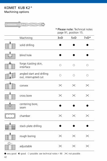
42
KOMET KUB K2®
3×D 5×D 7×D*
§ § §
§ § §
& & &
& & &
X X X
X X X
§ § §
X X X
§ § §
X X X
X X X
Machining
solid drilling
blind hole
forge /casting skin, interface
angled start and drilling out, interrupted cut
convex
cross bore
centering bore, seam
chamber
stack plate drilling
rough boring
adjustable
Machining options
§ very good $ good & possible: see technical notes E 90 X not possible
* Please note: Technical notes page 91, position 15.

43
KOMET KUB K2®
vc (m/min)
H70BK8425
H70BK2725
H71BK2725
H72BK7930
3×D / 5×D
x10-20,5
7×D
x10-20,5
min. opt. max.min. opt. max.min. opt. max.min. opt. max. min. opt. max. min. opt. max.
P
1.0
2.0
2.1
3.0
4.0
4.1
S
5.0
5.1
M
6.0
6.1
7.0
K
8.0
8.1
9.0
9.1
10.0
10.1
10.2
N
12.0
12.1
13.0
13.1
14.0
H
15.0
16.0
100120140100120140
0,150,180,220,160,180,20
100120140100120140
1001201400,150,200,25
0,150,180,2280 100120
80 10012080 100120
0,200,250,300,180,220,28
70 90 11070 90 110
70 90 1100,200,250,30
0,180,220,2850 70 90
50 70 9050 70 90
0,150,200,250,140,180,22
40 60 8040 60 80
0,100,150,200,080,130,18
30 50 700,100,120,14
0,080,100,1230 50 70
0,100,120,140,080,100,12
70 90 11070 90 110
0,200,300,400,200,280,38
60 80 10060 80 100
0,200,300,400,200,280,38
60 80 10060 80 100
0,250,350,450,200,300,40
50 70 9050 70 90
0,250,350,450,200,300,40
50 70 9050 70 90
0,250,350,450,200,300,40
30 50 7030 50 70
0,200,250,350,180,220,30
40 60 8040 60 80
0,250,350,450,200,300,40
Guideline values for solid drillingM
ater
ial g
roup
Sele
ctio
n: L
.H. f
old
page
f (mm/rev)Cutting speed Feed
Important: For more application details and safety notes see E 86-87!

44
2×D 3×D
§ §
§ §
§ §
§ §
§ §
§ §
§ §
§ §
§ §
$ $
$ $
KOMET KUB Quatron®
Machining
solid drilling
blind hole
forge /casting skin, interface
angled start and drilling out, interrupted cut
convex
cross bore
centering bore, seam
chamber
stack plate drilling
rough boring
adjustable
Machining options
§ very good $ good & possible: see technical notes E 92 X not possible

45
W83..01 W83..03 W83..13 W83..21
-01 -03 -13 -21
P
M
K
N
S
H
P
M
K
N
S
H
P
M
K
N
S
H
P
M
K
N
S
H
KOMET KUB Quatron®
BK8425
BK7935 BK7710
BK2730
BK7615
BK7710
BK7615
BK8430 BK8425 BK8430
BK7710
BK8430 BK7935
BK7710
BK6420 BK6730
BK74 BK6730 BK6130
BK6115
BK7935
BK8430
BK6420
Basic recommendation
alternative for better chip control
alternative for higher cutting speed E 48-49
alternative for greater strength
Guideline values for solid drilling with KUB Quatron® E 46-47
Insert selection W83
only as external cutting edge (recommendation internal cutting edge: W83..01 in BK8425)
also as internal cutting
edge

46
KOMET KUB Quatron®
2×D 3×D
P
1.0
2.0
2.1
3.0
4.0
4.1
S
5.0
5.1
M
6.0
6.1
7.0
K
8.0
8.1
9.0
9.1
10.0
10.1
10.2
N
12.0
12.1
13.0
13.1
14.0
H
15.0
16.0
x 1
4 –
15,9
x 1
6 –
17,5
x 1
7,6
– 21
,5
x 2
1,6
– 27
x 2
8 –
33
x 3
4 –
44
x 4
5 –
54
x 5
5 –
65
x 1
4 –
15,9
x 1
6 –
17,5
x 1
7,6
– 21
,5
x 2
1,6
– 27
x 2
8 –
33
x 3
4 –
44
x 4
5 –
54
x 5
5 –
65
300 0,10 0,12 0,12 0,14 0,14 0,14 0,14 0,14 0,10 0,12 0,12 0,14 0,14 0,14 0,14 0,14
250 0,12 0,14 0,16 0,20 0,20 0,25 0,20 0,20 0,12 0,14 0,16 0,20 0,20 0,25 0,20 0,20
300 0,14 0,16 0,18 0,25 0,25 0,30 0,25 0,25 0,14 0,16 0,18 0,25 0,25 0,30 0,25 0,25
200 0,14 0,16 0,18 0,20 0,20 0,25 0,20 0,20 0,14 0,16 0,18 0,20 0,20 0,25 0,20 0,20
180 0,10 0,12 0,14 0,18 0,18 0,20 0,18 0,18 0,10 0,12 0,14 0,18 0,18 0,20 0,18 0,18
80 0,08 0,10 0,12 0,14 0,16 0,18 0,14 0,16 0,08 0,10 0,12 0,14 0,14
60 0,06 0,08 0,10 0,12 0,12 0,12 0,12 0,12 0,06 0,08 0,10 0,12 0,12 0,12 0,12 0,12
80 0,06 0,08 0,10 0,12 0,12 0,12 0,12 0,12 0,06 0,08 0,10 0,12 0,12 0,12 0,12 0,12
180 0,08 0,10 0,12 0,14 0,14 0,16 0,14 0,14 0,08 0,10 0,12 0,14 0,14 0,16 0,14 0,14
160 0,08 0,08 0,12 0,16 0,16 0,20 0,16 0,16 0,08 0,08 0,12 0,16 0,16 0,20 0,16 0,16
160 0,06 0,08 0,10 0,12 0,12 0,14 0,12 0,12 0,06 0,08 0,10 0,12 0,12 0,14 0,12 0,12
200 0,16 0,16 0,25 0,30 0,30 0,30 0,30 0,30 0,16 0,16 0,25 0,30 0,30 0,30 0,30 0,30
160 0,14 0,16 0,18 0,20 0,20 0,25 0,20 0,20 0,14 0,16 0,18 0,20 0,20 0,25 0,20 0,20
180 0,14 0,16 0,18 0,20 0,20 0,25 0,20 0,20 0,14 0,16 0,18 0,20 0,20 0,25 0,20 0,20
160 0,14 0,16 0,18 0,22 0,22 0,25 0,22 0,22 0,14 0,16 0,18 0,22 0,22 0,25 0,22 0,22
140 0,14 0,16 0,18 0,22 0,22 0,25 0,22 0,22 0,14 0,16 0,18 0,22 0,22 0,25 0,22 0,22
140 0,14 0,16 0,18 0,22 0,25 0,25 0,22 0,25 0,14 0,16 0,18 0,22 0,25 0,25 0,22 0,25
120 0,10 0,12 0,16 0,20 0,20 0,25 0,20 0,20 0,10 0,12 0,16 0,20 0,20 0,25 0,20 0,20
300 0,12 0,14 0,16 0,25 0,20 0,25 0,25 0,20 0,12 0,14 0,16 0,25 0,20 0,25 0,25 0,20
400 0,08 0,08 0,10 0,12 0,12 0,15 0,12 0,12 0,08 0,08 0,10 0,12 0,12 0,15 0,12 0,12
600 0,08 0,08 0,10 0,12 0,12 0,12 0,12 0,12 0,08 0,08 0,10 0,12 0,12 0,12 0,12 0,12
300 0,10 0,12 0,14 0,16 0,16 0,20 0,16 0,16 0,10 0,12 0,14 0,16 0,16 0,20 0,16 0,16
250 0,10 0,12 0,14 0,20 0,20 0,30 0,20 0,20 0,10 0,12 0,14 0,20 0,20 0,30 0,20 0,20
80 0,05 0,05 0,08 0,10 0,10 0,10 0,10 0,10 0,05 0,05 0,08 0,10 0,10 0,10 0,10 0,10
40 0,05 0,05 0,08 0,10 0,10 0,10 0,10 0,10 0,05 0,05 0,08 0,10 0,10 0,10 0,10 0,10
Mat
eria
l gro
upSe
lect
ion:
L.H
. fol
d pa
ge
Cut
ting
spee
d v c
(m/m
in)
max. feed f (mm/rev) max. feed f (mm/rev)
Guideline values for solid drilling

47
KOMET KUB Quatron®
2×D 3×D
P
1.0
2.0
2.1
3.0
4.0
4.1
S
5.0
5.1
M
6.0
6.1
7.0
K
8.0
8.1
9.0
9.1
10.0
10.1
10.2
N
12.0
12.1
13.0
13.1
14.0
H
15.0
16.0
x 1
4 –
15,9
x 1
6 –
17,5
x 1
7,6
– 21
,5
x 2
1,6
– 27
x 2
8 –
33
x 3
4 –
44
x 4
5 –
54
x 5
5 –
65
x 1
4 –
15,9
x 1
6 –
17,5
x 1
7,6
– 21
,5
x 2
1,6
– 27
x 2
8 –
33
x 3
4 –
44
x 4
5 –
54
x 5
5 –
65
300 0,10 0,12 0,12 0,14 0,14 0,14 0,14 0,14 0,10 0,12 0,12 0,14 0,14 0,14 0,14 0,14
250 0,12 0,14 0,16 0,20 0,20 0,25 0,20 0,20 0,12 0,14 0,16 0,20 0,20 0,25 0,20 0,20
300 0,14 0,16 0,18 0,25 0,25 0,30 0,25 0,25 0,14 0,16 0,18 0,25 0,25 0,30 0,25 0,25
200 0,14 0,16 0,18 0,20 0,20 0,25 0,20 0,20 0,14 0,16 0,18 0,20 0,20 0,25 0,20 0,20
180 0,10 0,12 0,14 0,18 0,18 0,20 0,18 0,18 0,10 0,12 0,14 0,18 0,18 0,20 0,18 0,18
80 0,08 0,10 0,12 0,14 0,16 0,18 0,14 0,16 0,08 0,10 0,12 0,14 0,14
60 0,06 0,08 0,10 0,12 0,12 0,12 0,12 0,12 0,06 0,08 0,10 0,12 0,12 0,12 0,12 0,12
80 0,06 0,08 0,10 0,12 0,12 0,12 0,12 0,12 0,06 0,08 0,10 0,12 0,12 0,12 0,12 0,12
180 0,08 0,10 0,12 0,14 0,14 0,16 0,14 0,14 0,08 0,10 0,12 0,14 0,14 0,16 0,14 0,14
160 0,08 0,08 0,12 0,16 0,16 0,20 0,16 0,16 0,08 0,08 0,12 0,16 0,16 0,20 0,16 0,16
160 0,06 0,08 0,10 0,12 0,12 0,14 0,12 0,12 0,06 0,08 0,10 0,12 0,12 0,14 0,12 0,12
200 0,16 0,16 0,25 0,30 0,30 0,30 0,30 0,30 0,16 0,16 0,25 0,30 0,30 0,30 0,30 0,30
160 0,14 0,16 0,18 0,20 0,20 0,25 0,20 0,20 0,14 0,16 0,18 0,20 0,20 0,25 0,20 0,20
180 0,14 0,16 0,18 0,20 0,20 0,25 0,20 0,20 0,14 0,16 0,18 0,20 0,20 0,25 0,20 0,20
160 0,14 0,16 0,18 0,22 0,22 0,25 0,22 0,22 0,14 0,16 0,18 0,22 0,22 0,25 0,22 0,22
140 0,14 0,16 0,18 0,22 0,22 0,25 0,22 0,22 0,14 0,16 0,18 0,22 0,22 0,25 0,22 0,22
140 0,14 0,16 0,18 0,22 0,25 0,25 0,22 0,25 0,14 0,16 0,18 0,22 0,25 0,25 0,22 0,25
120 0,10 0,12 0,16 0,20 0,20 0,25 0,20 0,20 0,10 0,12 0,16 0,20 0,20 0,25 0,20 0,20
300 0,12 0,14 0,16 0,25 0,20 0,25 0,25 0,20 0,12 0,14 0,16 0,25 0,20 0,25 0,25 0,20
400 0,08 0,08 0,10 0,12 0,12 0,15 0,12 0,12 0,08 0,08 0,10 0,12 0,12 0,15 0,12 0,12
600 0,08 0,08 0,10 0,12 0,12 0,12 0,12 0,12 0,08 0,08 0,10 0,12 0,12 0,12 0,12 0,12
300 0,10 0,12 0,14 0,16 0,16 0,20 0,16 0,16 0,10 0,12 0,14 0,16 0,16 0,20 0,16 0,16
250 0,10 0,12 0,14 0,20 0,20 0,30 0,20 0,20 0,10 0,12 0,14 0,20 0,20 0,30 0,20 0,20
80 0,05 0,05 0,08 0,10 0,10 0,10 0,10 0,10 0,05 0,05 0,08 0,10 0,10 0,10 0,10 0,10
40 0,05 0,05 0,08 0,10 0,10 0,10 0,10 0,10 0,05 0,05 0,08 0,10 0,10 0,10 0,10 0,10
Mat
eria
l gro
upSe
lect
ion:
L.H
. fol
d pa
ge
Cut
ting
spee
d v c
(m/m
in)
max. feed f (mm/rev) max. feed f (mm/rev)
Guideline values for solid drilling
Important: For more application details and safety notes see E 86-87!

48
KOMET KUB Quatron®
P M M K NBK8425BK8430 BK7935 BK2730 BK6420 BK6115
BK6730BK8425BK8430 BK7935 BK2730 BK6420 BK74 BK6115
BK6730 BK6130 BK8425 BK7615 BK6115 BK7710
40 4050 5060 6070 7080 8090 90100 100110 110120 120130 130140 140150 150160 160170 170180 180190 190200 200210 210220 220230 230240 240250 250260 260270 270280 280290 290300 300310 310320 320330 330340 340350 350360 360370 370380 380390 390400 400410 410420 420430 430440 440450 450460 460470 470480 480490 490500 500600 600700 700800 800900 9001000 10001100 1100
vc (m/min)
Guideline values for solid drilling
Cutting speed

49
KOMET KUB Quatron®
P M M K NBK8425BK8430 BK7935 BK2730 BK6420 BK6115
BK6730BK8425BK8430 BK7935 BK2730 BK6420 BK74 BK6115
BK6730 BK6130 BK8425 BK7615 BK6115 BK7710
40 4050 5060 6070 7080 8090 90
100 100110 110120 120130 130140 140150 150160 160170 170180 180190 190200 200210 210220 220230 230240 240250 250260 260270 270280 280290 290300 300310 310320 320330 330340 340350 350360 360370 370380 380390 390400 400410 410420 420430 430440 440450 450460 460470 470480 480490 490500 500600 600700 700800 800900 9001000 10001100 1100
vc (m/min)
Guideline values for solid drilling
Cutting speed
Important: For more application details and safety notes see E 86-87!

50
4×D 5×D
§ §
§ §
$ $
$ $
$ $
$ $
$ $
& X
$ $
X X
$ $
KOMET KUB Pentron®
Machining
solid drilling
blind hole
forge /casting skin, interface
angled start and drilling out, interrupted cut
convex
cross bore
centering bore, seam
chamber
stack plate drilling
rough boring
adjustable
Machining options
§ very good $ good & possible: see technical notes E 98 X not possible
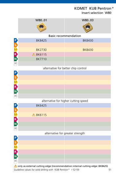
51
KOMET KUB Pentron®
W80..01 W80..03
P
M
K
N
S
H
P
M
K
N
S
H
P
M
K
N
S
H
P
M
K
N
S
H
BK8425 BK8430
BK2730 BK8430
BK6115
BK7710
BK6425
BK6115
Guideline values for solid drilling with KUB Pentron® E 52-59
Insert selection W80
only as external cutting edge (recommendation internal cutting edge: BK8425)
Basic recommendation
alternative for better chip control
alternative for higher cutting speed
alternative for greater strength

52
vc (m/min)
BK8425 BK2730 BK6425 BK6115 BK7710
min. opt. max. min. opt. max. min. opt. max. min. opt. max. min. opt. max.
P
1.0
2.0
2.1
3.0
4.0
4.1
S
5.0
5.1
M
6.0
6.1
7.0
K
8.0
8.1
9.0
9.1
10.0
10.1
10.2
N
12.0
12.1
13.0
13.1
14.0
H
15.0
16.0
KOMET KUB Pentron®4×D
200 260 320200 250 300
270 320 370250 300 350
250 270 300250 270 300
250 280 320250 270 300
200 260 320160 220 280
270 320 370250 300 350
140 180 220120 160 200
220 260 300200 240 280
120 160 200100 140 180
190 220 250170 200 230
50 70 9040 60 80
80 100 12070 90 110
150 170 210140 180 220
190 220 250210 240 270
120 150 200120 160 200
170 200 230190 220 250
110 150 190120 160 200
170 200 230190 220 250
140 180 220120 160 200
150 200 250160 240 320
120 150 180100 130 160
100 140 180100 140 180
140 180 220120 160 200
120 160 200120 160 200
120 150 180110 130 160
100 140 180100 140 180
110 140 17090 120 150
90 120 15090 120 150
110 140 17090 120 150
90 120 15090 120 150
90 110 13080 100 120
70 100 13070 100 130
150 200 250150 200 250
150 250 350200 300 400
200 300 400250 350 450
300 400 500300 400 500
300 500 700180 250 320
180 250 320210 280 350
150 200 250150 200 250
140 220 300
Mat
eria
l gro
upSe
lect
ion:
L.H
. fol
d pa
ge
Cutting speed
Guideline values for solid drilling

53
KOMET KUB Pentron®
4×D
x14,0-15,0
x15,1-16,0
x16,1-17,0
x17,1-18,0
x18,1-19,0
x19,1-20,0
min. opt. max.min. opt. max.min. opt. max.min. opt. max.min. opt. max.min. opt. max.
P
1.0
2.0
2.1
3.0
4.0
4.1
S
5.0
5.1
M
6.0
6.1
7.0
K
8.0
8.1
9.0
9.1
10.0
10.1
10.2
N
12.0
12.1
13.0
13.1
14.0
H
15.0
16.0
4×D
0,040,060,080,040,070,08
0,050,070,100,060,090,12
0,050,070,100,050,070,10
0,040,060,080,040,080,09
0,100,120,140,100,120,14
0,100,120,150,100,120,15
0,060,080,120,080,110,16
0,100,130,160,100,130,16
0,110,130,160,110,130,16
0,060,080,120,080,120,16
0,110,140,160,110,140,16
0,110,140,160,110,140,16
0,060,080,120,060,100,12
0,100,120,140,100,120,15
0,090,120,150,090,120,15
– – – – – –
0,060,080,120,080,100,12
0,080,100,120,080,100,12
0,080,100,120,080,100,12
0,060,080,120,080,100,12
0,080,100,120,080,100,12
0,080,100,120,080,100,12
0,060,080,100,060,080,10
0,060,080,100,060,080,10
0,060,080,100,060,080,10
0,080,120,160,100,150,18
0,100,150,180,100,150,18
0,120,150,180,120,150,18
0,080,100,140,100,130,16
0,100,130,160,100,130,16
0,100,130,160,100,130,16
0,080,120,160,120,150,18
0,120,150,180,120,150,18
0,120,150,180,120,150,18
0,080,120,160,120,150,18
0,120,150,180,120,150,18
0,120,150,180,120,150,18
0,080,120,160,120,150,18
0,120,150,180,120,150,18
0,120,150,180,120,150,18
0,080,120,140,100,130,16
0,100,130,160,100,130,16
0,100,130,160,100,130,16
0,080,100,120,090,120,15
0,090,120,150,090,120,15
0,090,120,150,090,120,15
0,080,100,120,080,110,13
0,100,120,140,100,130,15
0,100,130,150,100,130,15
0,080,100,120,080,100,14
0,080,110,150,080,110,15
0,080,110,130,080,110,15
0,080,100,120,080,100,14
0,080,110,150,080,110,15
0,080,110,130,080,110,15
0,080,100,140,100,120,16
0,100,130,150,100,130,15
0,100,130,150,100,130,15
0,100,120,150,100,140,16
0,120,140,170,130,150,17
0,130,160,180,130,160,18
Guideline values for solid drillingM
ater
ial g
roup
Sele
ctio
n: L
.H. f
old
page
Feed f (mm/rev)
on request
on request
on request
on request
Important: For more application details and safety notes see E 86-87!

54
4×D 4×D
x20,1-22,0
x22,1-23,0
x23,1-24,0
x24,1-25,0
x25,1-26,0
x26,1-28,0
x28,1-30,0
x30,1-33,0
x33,1-37,0
x37,1-42,0
x42,1-46,0
min. opt. max. min. opt. max. min. opt. max. min. opt. max. min. opt. max. min. opt. max. min. opt. max. min. opt. max. min. opt. max. min. opt. max. min. opt. max.
P
1.0
2.0
2.1
3.0
4.0
4.1
S
5.0
5.1
M
6.0
6.1
7.0
K
8.0
8.1
9.0
9.1
10.0
10.1
10.2
N
12.0
12.1
13.0
13.1
14.0
H
15.0
16.0
KOMET KUB Pentron®4×D
0,06 0,09 0,120,06 0,09 0,12
0,06 0,09 0,120,06 0,09 0,12
0,06 0,09 0,120,060,090,12
0,060,090,120,060,090,12
0,060,090,120,060,090,12
0,060,090,120,11 0,13 0,16
0,11 0,13 0,160,11 0,13 0,16
0,11 0,13 0,160,11 0,13 0,16
0,110,130,160,110,130,16
0,110,130,160,110,130,16
0,110,130,160,110,130,16
0,13 0,15 0,180,13 0,15 0,18
0,13 0,15 0,180,13 0,15 0,18
0,13 0,15 0,180,150,180,20
0,150,180,200,150,180,20
0,150,180,200,150,180,20
0,150,180,200,13 0,15 0,18
0,12 0,16 0,200,14 0,18 0,22
0,14 0,18 0,220,14 0,18 0,22
0,140,180,220,140,180,22
0,140,180,220,140,180,22
0,140,180,220,140,180,22
0,12 0,16 0,200,13 0,15 0,18
0,14 0,18 0,220,14 0,18 0,22
0,14 0,18 0,220,140,180,22
0,140,180,220,140,180,22
0,140,180,220,140,180,22
0,140,180,22
– – – – – – – – – – –
0,10 0,13 0,150,12 0,15 0,18
0,12 0,15 0,180,12 0,15 0,18
0,12 0,15 0,180,100,140,18
0,100,140,180,100,140,18
0,100,140,180,100,140,18
0,100,140,180,10 0,13 0,15
0,12 0,15 0,180,12 0,15 0,18
0,12 0,15 0,180,12 0,15 0,18
0,120,150,180,120,150,18
0,120,150,180,120,150,18
0,120,150,180,120,150,18
0,09 0,11 0,130,09 0,11 0,13
0,10 0,14 0,160,10 0,14 0,16
0,10 0,14 0,160,100,140,16
0,100,140,160,100,140,16
0,100,140,160,100,140,16
0,100,140,160,14 0,18 0,22
0,14 0,18 0,220,16 0,20 0,25
0,18 0,22 0,270,20 0,25 0,30
0,200,250,300,200,250,30
0,200,250,300,200,250,30
0,200,250,300,200,250,30
0,12 0,16 0,200,12 0,16 0,20
0,14 0,18 0,230,16 0,20 0,24
0,18 0,23 0,280,180,230,28
0,180,230,280,180,230,28
0,180,230,280,180,230,28
0,180,230,280,14 0,18 0,22
0,14 0,18 0,220,16 0,20 0,25
0,18 0,22 0,270,20 0,25 0,30
0,200,250,300,200,250,30
0,200,250,300,200,250,30
0,200,250,300,200,250,30
0,14 0,18 0,220,14 0,18 0,22
0,16 0,20 0,250,18 0,22 0,27
0,20 0,25 0,300,200,250,30
0,200,250,300,200,250,30
0,200,250,300,200,250,30
0,200,250,300,14 0,18 0,22
0,14 0,18 0,220,16 0,20 0,25
0,18 0,22 0,270,20 0,25 0,30
0,200,250,300,200,250,30
0,200,250,300,200,250,30
0,200,250,300,200,250,30
0,12 0,16 0,200,12 0,16 0,20
0,14 0,18 0,230,16 0,20 0,24
0,18 0,23 0,280,180,230,28
0,180,230,280,180,230,28
0,180,230,280,180,230,28
0,180,230,280,11 0,15 0,19
0,11 0,15 0,190,13 0,17 0,22
0,15 0,19 0,230,17 0,22 0,27
0,170,220,270,170,220,27
0,170,220,270,170,220,27
0,170,220,270,170,220,27
0,10 0,13 0,150,12 0,15 0,18
0,12 0,15 0,180,12 0,15 0,18
0,12 0,15 0,180,120,150,18
0,120,150,180,120,150,18
0,120,150,180,120,150,18
0,120,150,180,08 0,11 0,13
0,10 0,13 0,160,10 0,13 0,16
0,10 0,13 0,160,10 0,13 0,16
0,100,130,160,100,130,16
0,100,130,160,100,130,16
0,100,130,160,100,130,16
0,08 0,11 0,130,10 0,13 0,16
0,10 0,13 0,160,10 0,13 0,16
0,10 0,13 0,160,100,130,16
0,100,130,160,100,130,16
0,100,130,160,100,130,16
0,100,130,160,10 0,13 0,15
0,12 0,15 0,180,12 0,15 0,18
0,12 0,15 0,180,12 0,15 0,18
0,120,150,180,120,150,18
0,120,150,180,120,150,18
0,120,150,180,120,150,18
0,13 0,16 0,180,15 0,18 0,21
0,15 0,18 0,210,15 0,18 0,21
0,15 0,18 0,210,150,180,21
0,150,180,210,150,180,21
0,150,180,210,150,180,21
0,150,180,21
Mat
eria
l gro
upSe
lect
ion:
L.H
. fol
d pa
ge
Feed f (mm/rev) Feed f (mm/rev)
on request
on request
on request
on request
Guideline values for solid drilling

55
4×D 4×D
x20,1-22,0
x22,1-23,0
x23,1-24,0
x24,1-25,0
x25,1-26,0
x26,1-28,0
x28,1-30,0
x30,1-33,0
x33,1-37,0
x37,1-42,0
x42,1-46,0
min. opt. max. min. opt. max. min. opt. max. min. opt. max. min. opt. max. min. opt. max. min. opt. max. min. opt. max. min. opt. max. min. opt. max. min. opt. max.
P
1.0
2.0
2.1
3.0
4.0
4.1
S
5.0
5.1
M
6.0
6.1
7.0
K
8.0
8.1
9.0
9.1
10.0
10.1
10.2
N
12.0
12.1
13.0
13.1
14.0
H
15.0
16.0
KOMET KUB Pentron®4×D
0,06 0,09 0,120,06 0,09 0,12
0,06 0,09 0,120,06 0,09 0,12
0,06 0,09 0,120,060,090,12
0,060,090,120,060,090,12
0,060,090,120,060,090,12
0,060,090,120,11 0,13 0,16
0,11 0,13 0,160,11 0,13 0,16
0,11 0,13 0,160,11 0,13 0,16
0,110,130,160,110,130,16
0,110,130,160,110,130,16
0,110,130,160,110,130,16
0,13 0,15 0,180,13 0,15 0,18
0,13 0,15 0,180,13 0,15 0,18
0,13 0,15 0,180,150,180,20
0,150,180,200,150,180,20
0,150,180,200,150,180,20
0,150,180,200,13 0,15 0,18
0,12 0,16 0,200,14 0,18 0,22
0,14 0,18 0,220,14 0,18 0,22
0,140,180,220,140,180,22
0,140,180,220,140,180,22
0,140,180,220,140,180,22
0,12 0,16 0,200,13 0,15 0,18
0,14 0,18 0,220,14 0,18 0,22
0,14 0,18 0,220,140,180,22
0,140,180,220,140,180,22
0,140,180,220,140,180,22
0,140,180,22
– – – – – – – – – – –
0,10 0,13 0,150,12 0,15 0,18
0,12 0,15 0,180,12 0,15 0,18
0,12 0,15 0,180,100,140,18
0,100,140,180,100,140,18
0,100,140,180,100,140,18
0,100,140,180,10 0,13 0,15
0,12 0,15 0,180,12 0,15 0,18
0,12 0,15 0,180,12 0,15 0,18
0,120,150,180,120,150,18
0,120,150,180,120,150,18
0,120,150,180,120,150,18
0,09 0,11 0,130,09 0,11 0,13
0,10 0,14 0,160,10 0,14 0,16
0,10 0,14 0,160,100,140,16
0,100,140,160,100,140,16
0,100,140,160,100,140,16
0,100,140,160,14 0,18 0,22
0,14 0,18 0,220,16 0,20 0,25
0,18 0,22 0,270,20 0,25 0,30
0,200,250,300,200,250,30
0,200,250,300,200,250,30
0,200,250,300,200,250,30
0,12 0,16 0,200,12 0,16 0,20
0,14 0,18 0,230,16 0,20 0,24
0,18 0,23 0,280,180,230,28
0,180,230,280,180,230,28
0,180,230,280,180,230,28
0,180,230,280,14 0,18 0,22
0,14 0,18 0,220,16 0,20 0,25
0,18 0,22 0,270,20 0,25 0,30
0,200,250,300,200,250,30
0,200,250,300,200,250,30
0,200,250,300,200,250,30
0,14 0,18 0,220,14 0,18 0,22
0,16 0,20 0,250,18 0,22 0,27
0,20 0,25 0,300,200,250,30
0,200,250,300,200,250,30
0,200,250,300,200,250,30
0,200,250,300,14 0,18 0,22
0,14 0,18 0,220,16 0,20 0,25
0,18 0,22 0,270,20 0,25 0,30
0,200,250,300,200,250,30
0,200,250,300,200,250,30
0,200,250,300,200,250,30
0,12 0,16 0,200,12 0,16 0,20
0,14 0,18 0,230,16 0,20 0,24
0,18 0,23 0,280,180,230,28
0,180,230,280,180,230,28
0,180,230,280,180,230,28
0,180,230,280,11 0,15 0,19
0,11 0,15 0,190,13 0,17 0,22
0,15 0,19 0,230,17 0,22 0,27
0,170,220,270,170,220,27
0,170,220,270,170,220,27
0,170,220,270,170,220,27
0,10 0,13 0,150,12 0,15 0,18
0,12 0,15 0,180,12 0,15 0,18
0,12 0,15 0,180,120,150,18
0,120,150,180,120,150,18
0,120,150,180,120,150,18
0,120,150,180,08 0,11 0,13
0,10 0,13 0,160,10 0,13 0,16
0,10 0,13 0,160,10 0,13 0,16
0,100,130,160,100,130,16
0,100,130,160,100,130,16
0,100,130,160,100,130,16
0,08 0,11 0,130,10 0,13 0,16
0,10 0,13 0,160,10 0,13 0,16
0,10 0,13 0,160,100,130,16
0,100,130,160,100,130,16
0,100,130,160,100,130,16
0,100,130,160,10 0,13 0,15
0,12 0,15 0,180,12 0,15 0,18
0,12 0,15 0,180,12 0,15 0,18
0,120,150,180,120,150,18
0,120,150,180,120,150,18
0,120,150,180,120,150,18
0,13 0,16 0,180,15 0,18 0,21
0,15 0,18 0,210,15 0,18 0,21
0,15 0,18 0,210,150,180,21
0,150,180,210,150,180,21
0,150,180,210,150,180,21
0,150,180,21
Mat
eria
l gro
upSe
lect
ion:
L.H
. fol
d pa
ge
Feed f (mm/rev) Feed f (mm/rev)
on request
on request
on request
on request
Guideline values for solid drilling
Important: For more application details and safety notes see E 86-87!

56
vc (m/min)
BK8425 BK2730 BK6425 BK6115 BK7710
min. opt. max. min. opt. max. min. opt. max. min. opt. max. min. opt. max.
P
1.0
2.0
2.1
3.0
4.0
4.1
S
5.0
5.1
M
6.0
6.1
7.0
K
8.0
8.1
9.0
9.1
10.0
10.1
10.2
N
12.0
12.1
13.0
13.1
14.0
H
15.0
16.0
KOMET KUB Pentron®5×D
200 260 320200 250 300
270 320 370250 300 350
250 270 300250 270 300
250 280 320250 270 300
200 260 320160 220 280
270 320 370250 300 350
140 180 220120 160 200
220 260 300200 240 280
120 160 200100 140 180
190 220 250170 200 230
50 70 9040 60 80
80 100 12070 90 110
150 170 210140 180 220
190 220 250210 240 270
120 150 200120 160 200
170 200 230190 220 250
110 150 190120 160 200
170 200 230190 220 250
140 180 220120 160 200
150 200 250160 240 320
120 150 180100 130 160
100 140 180100 140 180
140 180 220120 160 200
120 160 200120 160 200
120 150 180110 130 160
100 140 180100 140 180
110 140 17090 120 150
90 120 15090 120 150
110 140 17090 120 150
90 120 15090 120 150
90 110 13080 100 120
70 100 13070 100 130
150 200 250150 200 250
150 250 350200 300 400
200 300 400250 350 450
300 400 500300 400 500
300 500 700180 250 320
180 250 320210 280 350
150 200 250150 200 250
140 220 300
Mat
eria
l gro
upSe
lect
ion:
L.H
. fol
d pa
ge
Cutting speed
Guideline values for solid drilling

57
KOMET KUB Pentron®5×D
x14,0-15,0
x15,1-16,0
x16,1-17,0
x17,1-18,0
x18,1-19,0
x19,1-20,0
min. opt. max.min. opt. max.min. opt. max.min. opt. max.min. opt. max.min. opt. max.
P
1.0
2.0
2.1
3.0
4.0
4.1
S
5.0
5.1
M
6.0
6.1
7.0
K
8.0
8.1
9.0
9.1
10.0
10.1
10.2
N
12.0
12.1
13.0
13.1
14.0
H
15.0
16.0
0,040,060,080,060,080,09
0,060,080,100,060,080,10
0,050,070,100,050,070,10
0,040,060,080,060,080,10
0,080,100,130,080,100,13
0,080,100,130,080,100,13
0,060,080,120,080,100,12
0,090,110,140,090,110,14
0,090,110,140,090,110,14
0,060,080,120,060,090,12
0,060,090,120,080,100,13
0,080,100,130,080,100,13
0,060,080,120,080,100,12
0,090,120,150,090,120,15
0,090,120,150,090,120,15
– – – – – –
0,060,080,100,060,080,10
0,060,080,100,060,080,10
0,060,080,100,060,080,10
0,060,080,100,060,080,10
0,060,080,100,060,080,10
0,060,080,100,060,080,10
0,060,080,100,060,080,10
0,060,080,100,060,080,10
0,060,080,100,060,080,10
0,080,100,140,080,120,15
0,100,130,160,100,130,16
0,100,130,160,100,130,16
0,080,100,140,080,100,13
0,080,110,140,080,110,14
0,080,110,140,080,110,14
0,080,100,130,080,120,15
0,100,130,160,100,130,16
0,100,130,160,100,130,16
0,080,100,130,080,120,15
0,100,130,160,100,130,16
0,100,130,160,100,130,16
0,080,100,130,080,120,15
0,100,130,160,100,130,16
0,100,130,160,100,130,16
0,080,100,120,080,100,13
0,080,110,140,080,110,14
0,080,110,140,080,110,14
0,060,100,120,060,100,13
0,070,100,140,070,100,14
0,070,100,140,070,100,14
0,080,100,120,080,120,14
0,100,130,150,100,130,15
0,100,130,150,100,130,15
0,080,100,120,080,100,14
0,080,110,150,080,110,15
0,080,110,130,080,110,15
0,080,100,120,080,100,14
0,080,110,150,080,110,15
0,080,110,130,080,110,15
0,080,100,120,080,120,14
0,100,130,150,100,130,15
0,100,130,150,100,130,15
0,100,120,150,120,150,17
0,130,160,180,130,160,18
0,130,160,180,130,160,18
Guideline values for solid drillingM
ater
ial g
roup
Sele
ctio
n: L
.H. f
old
page
5 × D inserting the drill at a reduced feed (-30%)Feed f (mm/rev)
on request
on request
on request
on request
Important: For more application details and safety notes see E 86-87!
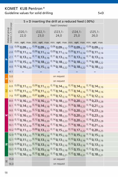
58
KOMET KUB Pentron®5×D
x20,1-22,0
x22,1-23,0
x23,1-24,0
x24,1-25,0
x25,1-26,0
x26,1-28,0
x28,1-30,0
x30,1-33,0
x33,1-37,0
x37,1-42,0
x42,1-46,0
min. opt. max. min. opt. max. min. opt. max. min. opt. max. min. opt. max. min. opt. max. min. opt. max. min. opt. max. min. opt. max. min. opt. max. min. opt. max.
P
1.0
2.0
2.1
3.0
4.0
4.1
S
5.0
5.1
M
6.0
6.1
7.0
K
8.0
8.1
9.0
9.1
10.0
10.1
10.2
N
12.0
12.1
13.0
13.1
14.0
H
15.0
16.0
0,06 0,09 0,120,06 0,09 0,12
0,06 0,09 0,120,06 0,09 0,12
0,06 0,09 0,120,080,100,12
0,080,100,120,080,100,12
0,080,100,120,080,100,12
0,080,100,120,09 0,11 0,14
0,09 0,11 0,140,09 0,11 0,14
0,09 0,11 0,140,09 0,11 0,14
0,090,110,140,090,110,14
0,090,110,140,090,110,14
0,090,110,140,090,110,14
0,11 0,13 0,160,11 0,13 0,16
0,11 0,13 0,160,11 0,13 0,16
0,11 0,13 0,160,110,150,18
0,110,150,180,110,150,18
0,110,150,180,110,150,18
0,110,150,180,13 0,15 0,18
0,14 0,18 0,200,14 0,18 0,22
0,14 0,18 0,220,14 0,18 0,22
0,100,150,200,100,150,20
0,100,150,200,100,150,20
0,100,150,200,100,150,20
0,12 0,16 0,200,13 0,15 0,18
0,14 0,18 0,220,14 0,18 0,22
0,14 0,18 0,220,140,180,22
0,140,180,220,140,180,20
0,140,180,200,140,180,20
0,140,180,20
– – – – – – – – – – –
0,09 0,11 0,130,09 0,11 0,13
0,10 0,14 0,160,10 0,14 0,16
0,10 0,14 0,160,100,140,16
0,100,140,160,100,140,16
0,100,140,160,100,140,16
0,100,140,160,09 0,11 0,13
0,09 0,11 0,130,12 0,14 0,16
0,12 0,14 0,160,12 0,14 0,16
0,080,110,140,080,110,14
0,080,110,140,080,110,14
0,080,110,140,080,110,14
0,07 0,09 0,110,07 0,09 0,11
0,10 0,12 0,140,10 0,12 0,14
0,10 0,12 0,140,100,120,14
0,100,120,140,100,120,14
0,100,120,140,100,120,14
0,100,120,140,12 0,16 0,20
0,12 0,16 0,200,14 0,18 0,23
0,16 0,20 0,250,18 0,23 0,28
0,180,230,280,180,230,28
0,180,230,280,180,230,28
0,180,230,280,180,230,28
0,10 0,14 0,180,10 0,14 0,18
0,12 0,16 0,210,14 0,18 0,22
0,16 0,21 0,260,160,200,26
0,160,200,260,160,200,26
0,160,200,260,160,200,26
0,160,200,260,12 0,16 0,20
0,12 0,16 0,200,14 0,18 0,23
0,16 0,20 0,250,18 0,23 0,28
0,180,230,280,180,230,28
0,180,230,280,180,230,28
0,180,230,280,180,230,28
0,12 0,16 0,200,12 0,16 0,20
0,14 0,18 0,230,16 0,20 0,25
0,18 0,23 0,280,180,230,28
0,180,230,280,180,230,28
0,180,230,280,180,230,28
0,180,230,280,12 0,16 0,20
0,12 0,16 0,200,14 0,18 0,23
0,16 0,20 0,250,18 0,23 0,28
0,180,230,280,180,230,28
0,180,230,280,180,230,28
0,180,230,280,180,230,28
0,10 0,12 0,180,10 0,14 0,18
0,12 0,16 0,210,14 0,18 0,23
0,16 0,21 0,260,160,210,26
0,160,210,260,160,210,26
0,160,210,260,160,210,26
0,160,210,260,09 0,11 0,17
0,09 0,13 0,170,11 0,15 0,20
0,13 0,17 0,220,15 0,20 0,25
0,150,200,250,150,200,25
0,150,200,250,150,200,25
0,150,200,250,150,200,25
0,10 0,13 0,150,12 0,15 0,18
0,12 0,15 0,180,12 0,15 0,18
0,12 0,15 0,180,120,150,18
0,120,150,180,120,150,18
0,120,150,180,120,150,18
0,120,150,180,08 0,11 0,13
0,10 0,13 0,160,10 0,13 0,16
0,10 0,13 0,160,10 0,13 0,16
0,100,130,160,100,130,16
0,100,130,160,100,130,16
0,100,130,160,100,130,16
0,08 0,11 0,130,10 0,13 0,16
0,10 0,13 0,160,10 0,13 0,16
0,10 0,13 0,160,100,130,16
0,100,130,160,100,130,16
0,100,130,160,100,130,16
0,100,130,160,10 0,13 0,15
0,12 0,15 0,180,12 0,15 0,18
0,12 0,15 0,180,12 0,15 0,18
0,120,150,180,120,150,18
0,120,150,180,120,150,18
0,120,150,180,120,150,18
0,13 0,16 0,180,15 0,18 0,21
0,15 0,18 0,210,15 0,18 0,21
0,15 0,18 0,210,150,180,21
0,150,180,210,150,180,21
0,150,180,210,150,180,21
0,150,180,21
Mat
eria
l gro
upSe
lect
ion:
L.H
. fol
d pa
ge
5 × D inserting the drill at a reduced feed (-30%) 5 × D inserting the drill at a reduced feed (-30%)Feed f (mm/rev) Feed f (mm/rev)
on request
on request
on request
on request
Guideline values for solid drilling

59
KOMET KUB Pentron®5×D
x20,1-22,0
x22,1-23,0
x23,1-24,0
x24,1-25,0
x25,1-26,0
x26,1-28,0
x28,1-30,0
x30,1-33,0
x33,1-37,0
x37,1-42,0
x42,1-46,0
min. opt. max. min. opt. max. min. opt. max. min. opt. max. min. opt. max. min. opt. max. min. opt. max. min. opt. max. min. opt. max. min. opt. max. min. opt. max.
P
1.0
2.0
2.1
3.0
4.0
4.1
S
5.0
5.1
M
6.0
6.1
7.0
K
8.0
8.1
9.0
9.1
10.0
10.1
10.2
N
12.0
12.1
13.0
13.1
14.0
H
15.0
16.0
0,06 0,09 0,120,06 0,09 0,12
0,06 0,09 0,120,06 0,09 0,12
0,06 0,09 0,120,080,100,12
0,080,100,120,080,100,12
0,080,100,120,080,100,12
0,080,100,120,09 0,11 0,14
0,09 0,11 0,140,09 0,11 0,14
0,09 0,11 0,140,09 0,11 0,14
0,090,110,140,090,110,14
0,090,110,140,090,110,14
0,090,110,140,090,110,14
0,11 0,13 0,160,11 0,13 0,16
0,11 0,13 0,160,11 0,13 0,16
0,11 0,13 0,160,110,150,18
0,110,150,180,110,150,18
0,110,150,180,110,150,18
0,110,150,180,13 0,15 0,18
0,14 0,18 0,200,14 0,18 0,22
0,14 0,18 0,220,14 0,18 0,22
0,100,150,200,100,150,20
0,100,150,200,100,150,20
0,100,150,200,100,150,20
0,12 0,16 0,200,13 0,15 0,18
0,14 0,18 0,220,14 0,18 0,22
0,14 0,18 0,220,140,180,22
0,140,180,220,140,180,20
0,140,180,200,140,180,20
0,140,180,20
– – – – – – – – – – –
0,09 0,11 0,130,09 0,11 0,13
0,10 0,14 0,160,10 0,14 0,16
0,10 0,14 0,160,100,140,16
0,100,140,160,100,140,16
0,100,140,160,100,140,16
0,100,140,160,09 0,11 0,13
0,09 0,11 0,130,12 0,14 0,16
0,12 0,14 0,160,12 0,14 0,16
0,080,110,140,080,110,14
0,080,110,140,080,110,14
0,080,110,140,080,110,14
0,07 0,09 0,110,07 0,09 0,11
0,10 0,12 0,140,10 0,12 0,14
0,10 0,12 0,140,100,120,14
0,100,120,140,100,120,14
0,100,120,140,100,120,14
0,100,120,140,12 0,16 0,20
0,12 0,16 0,200,14 0,18 0,23
0,16 0,20 0,250,18 0,23 0,28
0,180,230,280,180,230,28
0,180,230,280,180,230,28
0,180,230,280,180,230,28
0,10 0,14 0,180,10 0,14 0,18
0,12 0,16 0,210,14 0,18 0,22
0,16 0,21 0,260,160,200,26
0,160,200,260,160,200,26
0,160,200,260,160,200,26
0,160,200,260,12 0,16 0,20
0,12 0,16 0,200,14 0,18 0,23
0,16 0,20 0,250,18 0,23 0,28
0,180,230,280,180,230,28
0,180,230,280,180,230,28
0,180,230,280,180,230,28
0,12 0,16 0,200,12 0,16 0,20
0,14 0,18 0,230,16 0,20 0,25
0,18 0,23 0,280,180,230,28
0,180,230,280,180,230,28
0,180,230,280,180,230,28
0,180,230,280,12 0,16 0,20
0,12 0,16 0,200,14 0,18 0,23
0,16 0,20 0,250,18 0,23 0,28
0,180,230,280,180,230,28
0,180,230,280,180,230,28
0,180,230,280,180,230,28
0,10 0,12 0,180,10 0,14 0,18
0,12 0,16 0,210,14 0,18 0,23
0,16 0,21 0,260,160,210,26
0,160,210,260,160,210,26
0,160,210,260,160,210,26
0,160,210,260,09 0,11 0,17
0,09 0,13 0,170,11 0,15 0,20
0,13 0,17 0,220,15 0,20 0,25
0,150,200,250,150,200,25
0,150,200,250,150,200,25
0,150,200,250,150,200,25
0,10 0,13 0,150,12 0,15 0,18
0,12 0,15 0,180,12 0,15 0,18
0,12 0,15 0,180,120,150,18
0,120,150,180,120,150,18
0,120,150,180,120,150,18
0,120,150,180,08 0,11 0,13
0,10 0,13 0,160,10 0,13 0,16
0,10 0,13 0,160,10 0,13 0,16
0,100,130,160,100,130,16
0,100,130,160,100,130,16
0,100,130,160,100,130,16
0,08 0,11 0,130,10 0,13 0,16
0,10 0,13 0,160,10 0,13 0,16
0,10 0,13 0,160,100,130,16
0,100,130,160,100,130,16
0,100,130,160,100,130,16
0,100,130,160,10 0,13 0,15
0,12 0,15 0,180,12 0,15 0,18
0,12 0,15 0,180,12 0,15 0,18
0,120,150,180,120,150,18
0,120,150,180,120,150,18
0,120,150,180,120,150,18
0,13 0,16 0,180,15 0,18 0,21
0,15 0,18 0,210,15 0,18 0,21
0,15 0,18 0,210,150,180,21
0,150,180,210,150,180,21
0,150,180,210,150,180,21
0,150,180,21
Mat
eria
l gro
upSe
lect
ion:
L.H
. fol
d pa
ge
5 × D inserting the drill at a reduced feed (-30%) 5 × D inserting the drill at a reduced feed (-30%)Feed f (mm/rev) Feed f (mm/rev)
on request
on request
on request
on request
Guideline values for solid drilling
Important: For more application details and safety notes see E 86-87!

60
2×D 3×D 4×D
§ § §
§ § §
§ $ &
§ $ &
§ $ &
§ $ &
$ $ &
§ $ &
X X X
$ & X
$ $ $
KOMET KUB Trigon®
Machining
solid drilling
blind hole
forge /casting skin, interface
angled start and drilling out, interrupted cut
convex
cross bore
centering bore, seam
chamber
stack plate drilling
rough boring
adjustable
Machining options
§ very good $ good & possible: see technical notes E 92 X not possible

61
W29..01 W29..03 W29..11 W29..13 W29..20
-01 -03 -11 -13 -20
P
M
K
N
S
H
P
M
K
N
S
H
P
M
K
N
S
H
P
M
K
N
S
H
BK8425 BK77 BK8430
BK7930 BK2730
BK7615/BK62
BK7710
BK8425 BK8425
BK79
BK8425 BK79
BK72 BK6425
BK6425 BK7325
BK50
BK7930 / P40
BK7930 / P40
P40
BK7930
K10
Basic recommendation
alternative for better chip control
alternative for higher cutting speed E 64-65
alternative for greater strength
Guideline values for solid drilling with KUB Trigon® E 62-63
Insert selection W29
only as external cutting edge (recommendation internal cutting edge: W29..01 in BK8425)
KOMET KUB Trigon®, KUB® Drill
for softer cut

62
2×D 3×D 4×D
P
1.0
2.0
2.1
3.0
4.0
4.1
S
5.0
5.1
M
6.0
6.1
7.0
K
8.0
8.1
9.0
9.1
10.0
10.1
10.2
N
12.0
12.1
13.0
13.1
14.0
H
15.0
16.0
KOMET KUB Trigon®
x 1
4 –
16,9
x 1
7 –
19,9
x 2
0 –
24,9
x 2
5 –
29,9
x 3
0 –
36,9
x 3
7 –
40,9
x 4
1 –
44,0
x 1
4 –
16,9
x 1
7 –
19,9
x 2
0 –
24,9
x 2
5 –
29,9
x 3
0 –
36,9
x 3
7 –
40,9
x 4
1 –
44,0
x 1
4 –
16,9
x 1
7 –
19,9
x 2
0 –
24,9
x 2
5 –
29,9
x 3
0 –
36,9
x 3
7 –
40,9
x 4
1 –
44,0
300 0,08 0,10 0,10 0,12 0,12 0,12 0,12 0,08 0,10 0,10 0,12 0,12 0,12 0,12 0,06 0,08 0,08 0,10 0,10 0,10 0,10
250 0,06 0,08 0,12 0,14 0,14 0,14 0,16 0,06 0,08 0,12 0,14 0,14 0,14 0,16 0,04 0,06 0,10 0,12 0,12 0,12 0,14
300 0,08 0,10 0,12 0,14 0,16 0,16 0,20 0,08 0,10 0,12 0,14 0,16 0,16 0,20 0,06 0,08 0,10 0,12 0,14 0,14 0,18
200 0,06 0,08 0,10 0,14 0,16 0,16 0,16 0,06 0,08 0,10 0,14 0,16 0,16 0,16 0,04 0,06 0,08 0,12 0,14 0,14 0,14
180 0,06 0,08 0,10 0,12 0,12 0,12 0,14 0,06 0,08 0,10 0,12 0,12 0,12 0,14 0,04 0,06 0,08 0,10 0,10 0,10 0,12
80 0,04 0,06 0,08 0,10 0,10 0,12 0,12 0,04 0,06 0,08 0,10 0,10 0,12 0,12 0,02 0,04 0,06 0,08 0,08 0,10 0,10
60 0,04 0,06 0,08 0,10 0,10 0,10 0,10 0,04 0,06 0,08 0,10 0,10 0,10 0,10 0,02 0,04 0,06 0,08 0,08 0,08 0,08
80 0,06 0,08 0,10 0,12 0,10 0,12 0,12 0,06 0,08 0,10 0,12 0,10 0,12 0,12 0,04 0,06 0,08 0,10 0,08 0,10 0,10
180 0,06 0,08 0,10 0,14 0,14 0,14 0,14 0,06 0,08 0,10 0,14 0,14 0,14 0,14 0,04 0,06 0,08 0,12 0,12 0,12 0,12
160 0,06 0,06 0,08 0,12 0,12 0,12 0,14 0,06 0,06 0,08 0,12 0,12 0,12 0,14 0,04 0,04 0,06 0,10 0,10 0,10 0,12
160 0,06 0,06 0,08 0,12 0,12 0,12 0,12 0,06 0,06 0,08 0,12 0,12 0,12 0,12 0,04 0,04 0,06 0,10 0,10 0,10 0,12
200 0,10 0,12 0,14 0,20 0,20 0,20 0,25 0,10 0,12 0,14 0,20 0,20 0,20 0,25 0,08 0,10 0,12 0,18 0,18 0,18 0,23
160 0,08 0,08 0,10 0,14 0,14 0,16 0,18 0,08 0,08 0,10 0,14 0,14 0,16 0,18 0,06 0,06 0,08 0,12 0,12 0,14 0,16
180 0,08 0,10 0,14 0,20 0,20 0,20 0,25 0,08 0,10 0,14 0,20 0,20 0,20 0,25 0,06 0,08 0,12 0,18 0,18 0,18 0,23
160 0,08 0,10 0,14 0,20 0,20 0,20 0,25 0,08 0,10 0,14 0,20 0,20 0,20 0,25 0,06 0,08 0,12 0,18 0,18 0,18 0,23
140 0,10 0,12 0,16 0,25 0,16 0,18 0,18 0,10 0,12 0,16 0,25 0,16 0,18 0,18 0,08 0,10 0,14 0,23 0,23 0,23 0,23
140 0,08 0,10 0,14 0,20 0,20 0,20 0,25 0,08 0,10 0,14 0,20 0,20 0,20 0,25 0,06 0,08 0,12 0,18 0,18 0,18 0,23
120 0,08 0,10 0,14 0,16 0,16 0,16 0,20 0,08 0,10 0,14 0,16 0,16 0,16 0,20 0,06 0,08 0,12 0,14 0,14 0,14 0,18
300 0,05 0,08 0,12 0,16 0,16 0,18 0,20 0,05 0,08 0,12 0,16 0,16 0,18 0,20 0,03 0,06 0,10 0,14 0,14 0,16 0,18
400 0,05 0,08 0,08 0,10 0,10 0,10 0,12 0,05 0,08 0,08 0,10 0,10 0,10 0,12 0,03 0,06 0,06 0,08 0,08 0,08 0,10
600 0,05 0,08 0,08 0,10 0,10 0,12 0,12 0,05 0,08 0,08 0,10 0,10 0,12 0,12 0,03 0,06 0,06 0,08 0,08 0,10 0,10
300 0,10 0,12 0,14 0,18 0,18 0,20 0,20 0,10 0,12 0,14 0,18 0,18 0,20 0,20 0,08 0,10 0,12 0,16 0,16 0,18 0,18
250 0,10 0,12 0,14 0,20 0,20 0,20 0,25 0,10 0,12 0,14 0,20 0,20 0,20 0,25 0,08 0,10 0,12 0,18 0,18 0,18 0,23
80 0,05 0,05 0,08 0,10 0,10 0,12 0,12 0,05 0,05 0,08 0,10 0,10 0,12 0,12 0,03 0,03 0,06 0,08 0,08 0,10 0,10
40 0,05 0,08 0,08 0,10 0,10 0,10 0,10 0,05 0,08 0,08 0,10 0,10 0,10 0,10 0,03 0,06 0,06 0,08 0,08 0,08 0,08
Mat
eria
l gro
upSe
lect
ion:
L.H
. fol
d pa
ge
Cut
ting
spee
d v c
(m/m
in)
max. feed f (mm/rev) max. feed f (mm/rev) max. feed f (mm/rev)
Guideline values for solid drilling

63
2×D 3×D 4×D
P
1.0
2.0
2.1
3.0
4.0
4.1
S
5.0
5.1
M
6.0
6.1
7.0
K
8.0
8.1
9.0
9.1
10.0
10.1
10.2
N
12.0
12.1
13.0
13.1
14.0
H
15.0
16.0
KOMET KUB Trigon®
x 1
4 –
16,9
x 1
7 –
19,9
x 2
0 –
24,9
x 2
5 –
29,9
x 3
0 –
36,9
x 3
7 –
40,9
x 4
1 –
44,0
x 1
4 –
16,9
x 1
7 –
19,9
x 2
0 –
24,9
x 2
5 –
29,9
x 3
0 –
36,9
x 3
7 –
40,9
x 4
1 –
44,0
x 1
4 –
16,9
x 1
7 –
19,9
x 2
0 –
24,9
x 2
5 –
29,9
x 3
0 –
36,9
x 3
7 –
40,9
x 4
1 –
44,0
300 0,08 0,10 0,10 0,12 0,12 0,12 0,12 0,08 0,10 0,10 0,12 0,12 0,12 0,12 0,06 0,08 0,08 0,10 0,10 0,10 0,10
250 0,06 0,08 0,12 0,14 0,14 0,14 0,16 0,06 0,08 0,12 0,14 0,14 0,14 0,16 0,04 0,06 0,10 0,12 0,12 0,12 0,14
300 0,08 0,10 0,12 0,14 0,16 0,16 0,20 0,08 0,10 0,12 0,14 0,16 0,16 0,20 0,06 0,08 0,10 0,12 0,14 0,14 0,18
200 0,06 0,08 0,10 0,14 0,16 0,16 0,16 0,06 0,08 0,10 0,14 0,16 0,16 0,16 0,04 0,06 0,08 0,12 0,14 0,14 0,14
180 0,06 0,08 0,10 0,12 0,12 0,12 0,14 0,06 0,08 0,10 0,12 0,12 0,12 0,14 0,04 0,06 0,08 0,10 0,10 0,10 0,12
80 0,04 0,06 0,08 0,10 0,10 0,12 0,12 0,04 0,06 0,08 0,10 0,10 0,12 0,12 0,02 0,04 0,06 0,08 0,08 0,10 0,10
60 0,04 0,06 0,08 0,10 0,10 0,10 0,10 0,04 0,06 0,08 0,10 0,10 0,10 0,10 0,02 0,04 0,06 0,08 0,08 0,08 0,08
80 0,06 0,08 0,10 0,12 0,10 0,12 0,12 0,06 0,08 0,10 0,12 0,10 0,12 0,12 0,04 0,06 0,08 0,10 0,08 0,10 0,10
180 0,06 0,08 0,10 0,14 0,14 0,14 0,14 0,06 0,08 0,10 0,14 0,14 0,14 0,14 0,04 0,06 0,08 0,12 0,12 0,12 0,12
160 0,06 0,06 0,08 0,12 0,12 0,12 0,14 0,06 0,06 0,08 0,12 0,12 0,12 0,14 0,04 0,04 0,06 0,10 0,10 0,10 0,12
160 0,06 0,06 0,08 0,12 0,12 0,12 0,12 0,06 0,06 0,08 0,12 0,12 0,12 0,12 0,04 0,04 0,06 0,10 0,10 0,10 0,12
200 0,10 0,12 0,14 0,20 0,20 0,20 0,25 0,10 0,12 0,14 0,20 0,20 0,20 0,25 0,08 0,10 0,12 0,18 0,18 0,18 0,23
160 0,08 0,08 0,10 0,14 0,14 0,16 0,18 0,08 0,08 0,10 0,14 0,14 0,16 0,18 0,06 0,06 0,08 0,12 0,12 0,14 0,16
180 0,08 0,10 0,14 0,20 0,20 0,20 0,25 0,08 0,10 0,14 0,20 0,20 0,20 0,25 0,06 0,08 0,12 0,18 0,18 0,18 0,23
160 0,08 0,10 0,14 0,20 0,20 0,20 0,25 0,08 0,10 0,14 0,20 0,20 0,20 0,25 0,06 0,08 0,12 0,18 0,18 0,18 0,23
140 0,10 0,12 0,16 0,25 0,16 0,18 0,18 0,10 0,12 0,16 0,25 0,16 0,18 0,18 0,08 0,10 0,14 0,23 0,23 0,23 0,23
140 0,08 0,10 0,14 0,20 0,20 0,20 0,25 0,08 0,10 0,14 0,20 0,20 0,20 0,25 0,06 0,08 0,12 0,18 0,18 0,18 0,23
120 0,08 0,10 0,14 0,16 0,16 0,16 0,20 0,08 0,10 0,14 0,16 0,16 0,16 0,20 0,06 0,08 0,12 0,14 0,14 0,14 0,18
300 0,05 0,08 0,12 0,16 0,16 0,18 0,20 0,05 0,08 0,12 0,16 0,16 0,18 0,20 0,03 0,06 0,10 0,14 0,14 0,16 0,18
400 0,05 0,08 0,08 0,10 0,10 0,10 0,12 0,05 0,08 0,08 0,10 0,10 0,10 0,12 0,03 0,06 0,06 0,08 0,08 0,08 0,10
600 0,05 0,08 0,08 0,10 0,10 0,12 0,12 0,05 0,08 0,08 0,10 0,10 0,12 0,12 0,03 0,06 0,06 0,08 0,08 0,10 0,10
300 0,10 0,12 0,14 0,18 0,18 0,20 0,20 0,10 0,12 0,14 0,18 0,18 0,20 0,20 0,08 0,10 0,12 0,16 0,16 0,18 0,18
250 0,10 0,12 0,14 0,20 0,20 0,20 0,25 0,10 0,12 0,14 0,20 0,20 0,20 0,25 0,08 0,10 0,12 0,18 0,18 0,18 0,23
80 0,05 0,05 0,08 0,10 0,10 0,12 0,12 0,05 0,05 0,08 0,10 0,10 0,12 0,12 0,03 0,03 0,06 0,08 0,08 0,10 0,10
40 0,05 0,08 0,08 0,10 0,10 0,10 0,10 0,05 0,08 0,08 0,10 0,10 0,10 0,10 0,03 0,06 0,06 0,08 0,08 0,08 0,08
Mat
eria
l gro
upSe
lect
ion:
L.H
. fol
d pa
ge
Cut
ting
spee
d v c
(m/m
in)
max. feed f (mm/rev) max. feed f (mm/rev) max. feed f (mm/rev)
Guideline values for solid drilling
Important: For more application details and safety notes see E 86-87!

64
P M K NP25M P40 BK
79BK
7930BK8430BK8425
BK6440
BK6425
BK6420, BK72BK7325
BK6115 P40 BK
2730BK79
BK7930
BK7325BK6425
BK8425
BK6115 K10 BK
7615BK
6115BK62 K10 BK
77BK
7710BK50
40 4050 5060 6070 7080 8090 90100 100110 110120 120130 130140 140150 150160 160170 170180 180190 190200 200210 210220 220230 230240 240250 250260 260270 270280 280290 290300 300310 310320 320330 330340 340350 350360 360370 370380 380390 390400 400410 410420 420430 430440 440450 450460 460470 470480 480490 490500 500600 600700 700800 800900 9001000 10001100 1100
vc (m/min)
Guideline values for solid drilling
Cutting speed
KOMET KUB Trigon®, KUB® Drill, *KUB Centron®

65
P M K NP25M P40 BK
79BK
7930BK8430BK8425
BK6440
BK6425
BK6420, BK72BK7325
BK6115 P40 BK
2730BK79
BK7930
BK7325BK6425
BK8425
BK6115 K10 BK
7615BK
6115BK62 K10 BK
77BK
7710BK50
40 4050 5060 6070 7080 8090 90
100 100110 110120 120130 130140 140150 150160 160170 170180 180190 190200 200210 210220 220230 230240 240250 250260 260270 270280 280290 290300 300310 310320 320330 330340 340350 350360 360370 370380 380390 390400 400410 410420 420430 430440 440450 450460 460470 470480 480490 490500 500600 600700 700800 800900 9001000 10001100 1100
vc (m/min)
Guideline values for solid drillingKOMET KUB Trigon®, KUB® Drill, *KUB Centron®
until 1500
* Please note max. vc values of drill bit for KUB Centron® E 78
Important: For more application details and safety notes see E 86-87!

66
2×D 3×D
§ §
§ §
§ §
§ $
§ $
$ $
$ $
§ $
X X
$ X
$ $
Machining
solid drilling
blind hole
forge /casting skin, interface
angled start and drilling out, interrupted cut
convex
cross bore
centering bore, seam
chamber
stack plate drilling
rough boring
adjustable
Machining options
§ very good $ good & possible: see technical notes E 92 X not possible
KOMET KUB® Drill

67
2×D 3×D
P
1.0
2.0
2.1
3.0
4.0
4.1
S
5.0
5.1
M
6.0
6.1
7.0
K
8.0
8.1
9.0
9.1
10.0
10.1
10.2
N
12.0
12.1
13.0
13.1
14.0
H
15.0
16.0
x 4
5 –
54
x 5
4,5
– 68
x 6
8,5
– 82
x 4
5 –
54
x 5
4,5
– 68
x 6
8,5
– 82
300 0,12 0,14 0,16 0,12 0,14 0,14
250 0,16 0,20 0,25 0,16 0,20 0,20
300 0,20 0,25 0,25 0,20 0,25 0,25
200 0,16 0,20 0,20 0,16 0,18 0,18
180 0,14 0,16 0,16 0,14 0,14 0,16
60 0,10 0,12 0,14 0,10 0,12 0,14
80 0,12 0,14 0,16 0,12 0,14 0,14
180 0,14 0,16 0,16 0,14 0,14 0,16
160 0,14 0,16 0,16 0,14 0,16 0,16
160 0,12 0,16 0,18 0,12 0,16 0,16
200 0,25 0,30 0,30 0,25 0,25 0,30
160 0,18 0,30 0,30 0,18 0,20 0,25
180 0,25 0,30 0,30 0,25 0,25 0,30
160 0,25 0,30 0,30 0,25 0,25 0,30
140 0,25 0,30 0,30 0,25 0,25 0,30
140 0,25 0,30 0,30 0,25 0,25 0,30
120 0,20 0,25 0,30 0,20 0,20 0,20
300 0,20 0,25 0,25 0,20 0,20 0,25
400 0,12 0,16 0,16 0,12 0,12 0,14
600 0,12 0,12 0,14 0,12 0,12 0,14
300 0,20 0,25 0,25 0,20 0,25 0,25
250 0,25 0,30 0,30 0,25 0,30 0,30
80 0,12 0,14 0,14 0,12 0,14 0,14
40 0,10 0,10 0,10 0,10 0,10 0,10
Mat
eria
l gro
upSe
lect
ion:
L.H
. fol
d pa
ge
Cut
ting
spee
d v c
(m/m
in)
max. feed f (mm/rev) max. feed f (mm/rev)
Guideline values for solid drillingKOMET KUB® Drill
Important: For more application details and safety notes see E 86-87!

68
3×D
§
§
&
&
&
&
&
&
X
X
$
Machining
solid drilling
blind hole
forge /casting skin, interface
angled start and drilling out, interrupted cut
convex
cross bore
centering bore, seam
chamber
stack plate drilling
rough boring
adjustable
Machining options
§ very good $ good & possible: see technical notes E 92 X not possible
KOMET KUB® Drill, adjustable

69
3×D
P
1.0
2.0
2.1
3.0
4.0
4.1
S
5.0
5.1
M
6.0
6.1
7.0
K
8.0
8.1
9.0
9.1
10.0
10.1
10.2
N
12.0
12.1
13.0
13.1
14.0
H
15.0
16.0
x 3
8,5
– 44
x 4
4,5
– 54
x 5
4,5
– 68
x 6
8,5
– 82
300 0,10 0,12 0,12 0,14
250 0,10 0,12 0,12 0,14
300 0,12 0,14 0,14 0,16
200 0,10 0,12 0,12 0,14
180 0,08 0,10 0,10 0,12
80 0,06 0,08 0,08 0,10
60 0,06 0,08 0,08 0,10
80 0,06 0,08 0,08 0,10
180 0,08 0,10 0,10 0,12
160 0,08 0,10 0,10 0,12
160 0,06 0,08 0,08 0,10
200 0,16 0,18 0,18 0,23
160 0,16 0,18 0,18 0,23
180 0,14 0,16 0,16 0,18
160 0,14 0,16 0,16 0,18
140 0,12 0,14 0,14 0,16
140 0,10 0,12 0,12 0,14
120 0,12 0,14 0,14 0,16
300 0,14 0,16 0,16 0,18
400 0,14 0,16 0,16 0,18
600 0,14 0,16 0,16 0,18
300 0,16 0,18 0,18 0,23
250 0,16 0,18 0,18 0,23
80 0,06 0,08 0,08 0,10
40 0,04 0,06 0,06 0,08
Mat
eria
l gro
upSe
lect
ion:
L.H
. fol
d pa
ge
Cut
ting
spee
d v c
(m/m
in)
max. feed f (mm/rev)
Guideline values for solid drillingKOMET KUB® Drill, adjustable
Important: For more application details and safety notes see E 86-87!

70
KUB Centron® Powerline
§
§
$
&
&
&
&
X
X
X
X
KOMET KUB Centron® Powerline
Machining
solid drilling
blind hole
forge /casting skin, interface
angled start and drilling out, interrupted cut
convex
cross bore
centering bore, seam
chamber
stack plate drilling
rough boring
adjustable
Machining options
§ very good $ good & possible: see technical notes E 102 X not possible

71
W83..01 W83..03 W83..13 W83..21
-01 -03 -13 -21
P
M
K
N
S
H
P
M
K
N
S
H
P
M
K
N
S
H
P
M
K
N
S
H
KOMET KUB Centron® Powerline
BK8430
BK2730
BK2730
BK6115
BK7710
BK6115
BK8430 BK8425
BK8430 BK7935
BK7710
BK6420 BK6130
BK74 BK6130
BK6130
BK8425
BK7935
BK8425
Basic recommendation
alternative for better chip control
alternative for higher cutting speed E 48-49
alternative for greater strength
Guideline values for solid drilling with KUB Centron® Powerline E 72-75
Insert selection W83
also as internal cutting
edge

72
KOMET KUB Centron® Powerline
KUB Centron® Powerline 4×D – 9×D KUB Centron® Powerline 4×D – 9×D
X 20 – 24,9 X 25 – 29,9 X 30 – 32,9 X 33 – 36,9 X 37 – 39,9 X 40 – 44,9vc f vc f vc f vc f vc f vc f
m/min m/min m/min m/min m/min m/min
~4×D min. opt. max. ~~4×D min. opt. max. ~~4×D min. opt. max. ~4×D min. opt. max. ~4×D min. opt. max. ~4×D min. opt. max.
~ 6×D vc = –10% · ~ 8×D vc = –25% ~ 6×D vc = –10% · ~ 8×D vc = –25%
P
1.0
2.0
2.1
3.0
4.0
4.1
S
5.0
5.1
M
6.0
6.1
7.0
K
8.0
8.1
9.0
9.1
10.0
10.1
10.2
N
12.0
12.1
13.0
13.1
14.0
H
15.0
16.0
200 0,14 0,16 0,18 180 0,14 0,17 0,20 180 0,15 0,18 0,21 180 0,15 0,18 0,21 180 0,17 0,20 0,23 200 0,14 0,16 0,18
200 0,14 0,16 0,18 180 0,14 0,17 0,20 180 0,15 0,18 0,21 180 0,15 0,18 0,21 180 0,17 0,20 0,23 200 0,14 0,16 0,18
200 0,16 0,18 0,20 200 0,17 0,20 0,23 200 0,22 0,25 0,28 200 0,22 0,25 0,28 200 0,22 0,25 0,28 220 0,16 0,18 0,20
160 0,14 0,16 0,18 160 0,17 0,20 0,23 160 0,19 0,22 0,25 160 0,22 0,25 0,28 160 0,22 0,25 0,28 180 0,16 0,20 0,22
140 0,12 0,14 0,16 140 0,13 0,16 0,19 140 0,15 0,18 0,21 140 0,17 0,20 0,23 140 0,17 0,20 0,23 160 0,12 0,16 0,19
180 0,23 0,25 0,27 180 0,27 0,30 0,33 180 0,32 0,35 0,38 180 0,32 0,35 0,38 180 0,32 0,35 0,38 180 0,23 0,25 0,27
170 0,23 0,25 0,27 170 0,27 0,30 0,33 170 0,32 0,35 0,38 170 0,32 0,35 0,38 170 0,32 0,35 0,38 170 0,23 0,25 0,27
180 0,23 0,25 0,27 180 0,27 0,30 0,33 180 0,32 0,35 0,38 180 0,32 0,35 0,38 180 0,32 0,35 0,38 180 0,23 0,25 0,27
170 0,20 0,22 0,24 170 0,22 0,25 0,28 170 0,27 0,30 0,33 170 0,27 0,30 0,33 170 0,27 0,30 0,33 170 0,20 0,22 0,24
160 0,18 0,20 0,22 160 0,19 0,22 0,25 160 0,25 0,28 0,31 160 0,25 0,28 0,31 160 0,25 0,28 0,31 160 0,18 0,20 0,22
120 0,12 0,14 0,16 120 0,15 0,18 0,21 120 0,19 0,22 0,25 120 0,19 0,22 0,25 120 0,19 0,22 0,25 130 0,12 0,14 0,16
120 0,20 0,22 0,24 120 0,22 0,25 0,28 120 0,32 0,35 0,38 120 0,32 0,35 0,38 120 0,32 0,35 0,38 130 0,20 0,22 0,24
250 0,18 0,20 0,22 250 0,22 0,25 0,28 250 0,25 0,28 0,31 250 0,27 0,30 0,33 250 0,27 0,30 0,33 250 0,18 0,20 0,22
250 0,16 0,18 0,20 250 0,19 0,22 0,25 250 0,25 0,28 0,31 250 0,25 0,28 0,31 250 0,25 0,28 0,31 250 0,16 0,18 0,20
300 0,12 0,14 0,16 300 0,15 0,18 0,21 300 0,17 0,20 0,23 300 0,17 0,20 0,23 300 0,17 0,20 0,23 300 0,12 0,14 0,16
250 0,18 0,20 0,22 250 0,22 0,25 0,28 250 0,27 0,30 0,33 250 0,27 0,30 0,33 250 0,27 0,30 0,33 250 0,18 0,20 0,22
250 0,18 0,20 0,22 250 0,22 0,25 0,28 250 0,27 0,30 0,33 250 0,27 0,30 0,33 250 0,27 0,30 0,33 250 0,18 0,20 0,22
Guideline values for solid drilling
Mat
eria
l gro
upSe
lect
ion:
L.H
. fol
d pa
ge
Backing out of the bore with greatly reduced speed Backing out of the bore with greatly reduced speed
mm/rev mm/rev mm/rev mm/rev mm/rev mm/rev
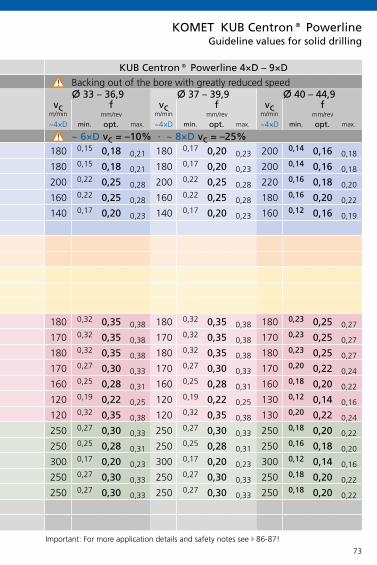
73
KOMET KUB Centron® Powerline
KUB Centron® Powerline 4×D – 9×D KUB Centron® Powerline 4×D – 9×D
X 20 – 24,9 X 25 – 29,9 X 30 – 32,9 X 33 – 36,9 X 37 – 39,9 X 40 – 44,9vc f vc f vc f vc f vc f vc f
m/min m/min m/min m/min m/min m/min
~4×D min. opt. max. ~~4×D min. opt. max. ~~4×D min. opt. max. ~4×D min. opt. max. ~4×D min. opt. max. ~4×D min. opt. max.
~ 6×D vc = –10% · ~ 8×D vc = –25% ~ 6×D vc = –10% · ~ 8×D vc = –25%
P
1.0
2.0
2.1
3.0
4.0
4.1
S
5.0
5.1
M
6.0
6.1
7.0
K
8.0
8.1
9.0
9.1
10.0
10.1
10.2
N
12.0
12.1
13.0
13.1
14.0
H
15.0
16.0
200 0,14 0,16 0,18 180 0,14 0,17 0,20 180 0,15 0,18 0,21 180 0,15 0,18 0,21 180 0,17 0,20 0,23 200 0,14 0,16 0,18
200 0,14 0,16 0,18 180 0,14 0,17 0,20 180 0,15 0,18 0,21 180 0,15 0,18 0,21 180 0,17 0,20 0,23 200 0,14 0,16 0,18
200 0,16 0,18 0,20 200 0,17 0,20 0,23 200 0,22 0,25 0,28 200 0,22 0,25 0,28 200 0,22 0,25 0,28 220 0,16 0,18 0,20
160 0,14 0,16 0,18 160 0,17 0,20 0,23 160 0,19 0,22 0,25 160 0,22 0,25 0,28 160 0,22 0,25 0,28 180 0,16 0,20 0,22
140 0,12 0,14 0,16 140 0,13 0,16 0,19 140 0,15 0,18 0,21 140 0,17 0,20 0,23 140 0,17 0,20 0,23 160 0,12 0,16 0,19
180 0,23 0,25 0,27 180 0,27 0,30 0,33 180 0,32 0,35 0,38 180 0,32 0,35 0,38 180 0,32 0,35 0,38 180 0,23 0,25 0,27
170 0,23 0,25 0,27 170 0,27 0,30 0,33 170 0,32 0,35 0,38 170 0,32 0,35 0,38 170 0,32 0,35 0,38 170 0,23 0,25 0,27
180 0,23 0,25 0,27 180 0,27 0,30 0,33 180 0,32 0,35 0,38 180 0,32 0,35 0,38 180 0,32 0,35 0,38 180 0,23 0,25 0,27
170 0,20 0,22 0,24 170 0,22 0,25 0,28 170 0,27 0,30 0,33 170 0,27 0,30 0,33 170 0,27 0,30 0,33 170 0,20 0,22 0,24
160 0,18 0,20 0,22 160 0,19 0,22 0,25 160 0,25 0,28 0,31 160 0,25 0,28 0,31 160 0,25 0,28 0,31 160 0,18 0,20 0,22
120 0,12 0,14 0,16 120 0,15 0,18 0,21 120 0,19 0,22 0,25 120 0,19 0,22 0,25 120 0,19 0,22 0,25 130 0,12 0,14 0,16
120 0,20 0,22 0,24 120 0,22 0,25 0,28 120 0,32 0,35 0,38 120 0,32 0,35 0,38 120 0,32 0,35 0,38 130 0,20 0,22 0,24
250 0,18 0,20 0,22 250 0,22 0,25 0,28 250 0,25 0,28 0,31 250 0,27 0,30 0,33 250 0,27 0,30 0,33 250 0,18 0,20 0,22
250 0,16 0,18 0,20 250 0,19 0,22 0,25 250 0,25 0,28 0,31 250 0,25 0,28 0,31 250 0,25 0,28 0,31 250 0,16 0,18 0,20
300 0,12 0,14 0,16 300 0,15 0,18 0,21 300 0,17 0,20 0,23 300 0,17 0,20 0,23 300 0,17 0,20 0,23 300 0,12 0,14 0,16
250 0,18 0,20 0,22 250 0,22 0,25 0,28 250 0,27 0,30 0,33 250 0,27 0,30 0,33 250 0,27 0,30 0,33 250 0,18 0,20 0,22
250 0,18 0,20 0,22 250 0,22 0,25 0,28 250 0,27 0,30 0,33 250 0,27 0,30 0,33 250 0,27 0,30 0,33 250 0,18 0,20 0,22
Guideline values for solid drilling
Important: For more application details and safety notes see E 86-87!
Mat
eria
l gro
upSe
lect
ion:
L.H
. fol
d pa
ge
Backing out of the bore with greatly reduced speed Backing out of the bore with greatly reduced speed
mm/rev mm/rev mm/rev mm/rev mm/rev mm/rev

74
KOMET KUB Centron® Powerline
KUB Centron® Powerline 4×D – 9×D KUB Centron® Powerline 4×D – 9×D
X 45 – 48,9 X 49 – 51,9 X 52 – 54,9 X 55 – 61,9 X 62 – 65,9vc f vc f vc f vc f vc f
m/min m/min m/min m/min m/min
~4×D min. opt. max. ~~4×D min. opt. max. ~~4×D min. opt. max. ~4×D min. opt. max. ~4×D min. opt. max.
~ 6×D vc = –10% · ~ 8×D vc = –25% ~ 6×D vc = –10% · ~ 8×D vc = –25%
P
1.0
2.0
2.1
3.0
4.0
4.1
S
5.0
5.1
M
6.0
6.1
7.0
K
8.0
8.1
9.0
9.1
10.0
10.1
10.2
N
12.0
12.1
13.0
13.1
14.0
H
15.0
16.0
180 0,14 0,16 0,18 200 0,14 0,17 0,18 180 0,14 0,17 0,18 180 0,14 0,17 0,18 200 0,14 0,17 0,18
180 0,14 0,16 0,18 200 0,14 0,17 0,18 180 0,14 0,17 0,18 180 0,14 0,17 0,18 200 0,14 0,17 0,18
200 0,17 0,20 0,22 220 0,20 0,23 0,25 200 0,20 0,25 0,28 200 0,20 0,25 0,28 220 0,20 0,23 0,25
160 0,16 0,20 0,22 180 0,18 0,20 0,24 160 0,18 0,20 0,24 160 0,18 0,20 0,24 180 0,18 0,20 0,24
140 0,12 0,16 0,19 160 0,12 0,16 0,19 140 0,17 0,20 0,23 140 0,17 0,20 0,23 160 0,17 0,20 0,23
170 0,23 0,25 0,27 180 0,27 0,30 0,33 170 0,27 0,30 0,33 170 0,27 0,30 0,33 180 0,23 0,25 0,27
160 0,23 0,25 0,27 170 0,27 0,30 0,33 160 0,27 0,30 0,33 160 0,27 0,30 0,33 170 0,23 0,25 0,27
170 0,23 0,25 0,27 180 0,27 0,30 0,33 170 0,27 0,30 0,33 170 0,27 0,30 0,33 180 0,23 0,25 0,27
160 0,20 0,22 0,24 170 0,22 0,25 0,28 160 0,22 0,25 0,28 160 0,22 0,25 0,28 170 0,20 0,22 0,24
150 0,18 0,20 0,22 160 0,19 0,22 0,25 150 0,19 0,22 0,25 150 0,19 0,22 0,25 160 0,18 0,20 0,22
120 0,12 0,14 0,16 130 0,15 0,18 0,21 120 0,15 0,18 0,21 130 0,15 0,18 0,21 120 0,12 0,14 0,16
120 0,20 0,22 0,24 130 0,22 0,25 0,28 120 0,22 0,25 0,28 130 0,22 0,25 0,28 120 0,20 0,22 0,24
240 0,18 0,20 0,22 250 0,22 0,25 0,28 240 0,22 0,25 0,28 240 0,22 0,25 0,28 250 0,18 0,20 0,22
240 0,16 0,18 0,20 250 0,19 0,22 0,25 240 0,19 0,22 0,25 240 0,19 0,22 0,25 250 0,16 0,18 0,20
280 0,12 0,14 0,16 300 0,15 0,18 0,21 280 0,15 0,18 0,21 280 0,15 0,18 0,21 300 0,12 0,14 0,16
240 0,18 0,20 0,22 250 0,22 0,25 0,28 240 0,22 0,25 0,28 240 0,22 0,25 0,28 250 0,18 0,20 0,22
240 0,18 0,20 0,22 250 0,22 0,25 0,28 240 0,22 0,25 0,28 240 0,22 0,25 0,28 250 0,18 0,20 0,22
Guideline values for solid drilling
Mat
eria
l gro
upSe
lect
ion:
L.H
. fol
d pa
ge
Backing out of the bore with greatly reduced speed Backing out of the bore with greatly reduced speed
mm/rev mm/rev mm/rev mm/rev mm/rev
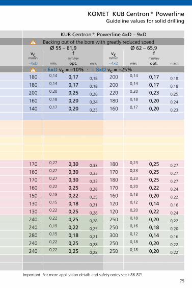
75
KOMET KUB Centron® Powerline
KUB Centron® Powerline 4×D – 9×D KUB Centron® Powerline 4×D – 9×D
X 45 – 48,9 X 49 – 51,9 X 52 – 54,9 X 55 – 61,9 X 62 – 65,9vc f vc f vc f vc f vc f
m/min m/min m/min m/min m/min
~4×D min. opt. max. ~~4×D min. opt. max. ~~4×D min. opt. max. ~4×D min. opt. max. ~4×D min. opt. max.
~ 6×D vc = –10% · ~ 8×D vc = –25% ~ 6×D vc = –10% · ~ 8×D vc = –25%
P
1.0
2.0
2.1
3.0
4.0
4.1
S
5.0
5.1
M
6.0
6.1
7.0
K
8.0
8.1
9.0
9.1
10.0
10.1
10.2
N
12.0
12.1
13.0
13.1
14.0
H
15.0
16.0
180 0,14 0,16 0,18 200 0,14 0,17 0,18 180 0,14 0,17 0,18 180 0,14 0,17 0,18 200 0,14 0,17 0,18
180 0,14 0,16 0,18 200 0,14 0,17 0,18 180 0,14 0,17 0,18 180 0,14 0,17 0,18 200 0,14 0,17 0,18
200 0,17 0,20 0,22 220 0,20 0,23 0,25 200 0,20 0,25 0,28 200 0,20 0,25 0,28 220 0,20 0,23 0,25
160 0,16 0,20 0,22 180 0,18 0,20 0,24 160 0,18 0,20 0,24 160 0,18 0,20 0,24 180 0,18 0,20 0,24
140 0,12 0,16 0,19 160 0,12 0,16 0,19 140 0,17 0,20 0,23 140 0,17 0,20 0,23 160 0,17 0,20 0,23
170 0,23 0,25 0,27 180 0,27 0,30 0,33 170 0,27 0,30 0,33 170 0,27 0,30 0,33 180 0,23 0,25 0,27
160 0,23 0,25 0,27 170 0,27 0,30 0,33 160 0,27 0,30 0,33 160 0,27 0,30 0,33 170 0,23 0,25 0,27
170 0,23 0,25 0,27 180 0,27 0,30 0,33 170 0,27 0,30 0,33 170 0,27 0,30 0,33 180 0,23 0,25 0,27
160 0,20 0,22 0,24 170 0,22 0,25 0,28 160 0,22 0,25 0,28 160 0,22 0,25 0,28 170 0,20 0,22 0,24
150 0,18 0,20 0,22 160 0,19 0,22 0,25 150 0,19 0,22 0,25 150 0,19 0,22 0,25 160 0,18 0,20 0,22
120 0,12 0,14 0,16 130 0,15 0,18 0,21 120 0,15 0,18 0,21 130 0,15 0,18 0,21 120 0,12 0,14 0,16
120 0,20 0,22 0,24 130 0,22 0,25 0,28 120 0,22 0,25 0,28 130 0,22 0,25 0,28 120 0,20 0,22 0,24
240 0,18 0,20 0,22 250 0,22 0,25 0,28 240 0,22 0,25 0,28 240 0,22 0,25 0,28 250 0,18 0,20 0,22
240 0,16 0,18 0,20 250 0,19 0,22 0,25 240 0,19 0,22 0,25 240 0,19 0,22 0,25 250 0,16 0,18 0,20
280 0,12 0,14 0,16 300 0,15 0,18 0,21 280 0,15 0,18 0,21 280 0,15 0,18 0,21 300 0,12 0,14 0,16
240 0,18 0,20 0,22 250 0,22 0,25 0,28 240 0,22 0,25 0,28 240 0,22 0,25 0,28 250 0,18 0,20 0,22
240 0,18 0,20 0,22 250 0,22 0,25 0,28 240 0,22 0,25 0,28 240 0,22 0,25 0,28 250 0,18 0,20 0,22
Guideline values for solid drilling
Important: For more application details and safety notes see E 86-87!
Mat
eria
l gro
upSe
lect
ion:
L.H
. fol
d pa
ge
Backing out of the bore with greatly reduced speed Backing out of the bore with greatly reduced speed
mm/rev mm/rev mm/rev mm/rev mm/rev

76
KUB Centron® KUB® V464
§ §
§ §
$ $
& &
& &
& &
& &
& &
X X
X X
X §
KOMET KUB Centron® / KUB® V464
ABS-T
Machining
solid drilling
blind hole
forge /casting skin, interface
angled start and drilling out, interrupted cut
convex
cross bore
centering bore, seam
chamber
stack plate drilling
rough boring
adjustable
Machining options
§ very good $ good & possible: see technical notes E 104 X not possible

77
KOMET KUB Centron® / KUB® V464
W29..01 W29..03 W29..11 W29..13 W29..20*
-01 -03 -11 -13 -20
P
M
K
N
S
H
P
M
K
N
S
H
P
M
K
N
S
H
P
M
K
N
S
H
BK8425 BK77 BK8430
BK79 BK2730
BK7615/BK62
BK7710
BK8425 BK8425
BK8425 BK79
BK72 BK6425
BK6425 BK7325
BK50
BK7930, P40
P40
BK7930
K10
Basic recommendation
alternative for better chip control
alternative for higher cutting speed E 64-65
alternative for greater strength
Guideline values for solid drilling with KUB Centron® E 78, KUB® V464 E 79
Insert selection W29
* for softer cut

78
KOMET KUB Centron®
KUB Centron® 4×D – 9×D KUB Centron® 4×D – 9×D KUB® V464 6×D
X 20 – 25 X 26 – 32 X 33 – 45 X 46 – 54 X 55 – 64 X 65 – 71 X 72 – 81 X 80–99 X100–119 X120–159HSS HSS HSS HSS HSS HSS HSS HSS HSS HSS
f vc vc f vc vc f vc vc f vc vc f vc vc f vc f vc f vc f vc f vcm/min m/min m/min m/min m/min m/min m/min m/min m/min m/min m/min m/min m/min m/min m/min
P
1.0
2.0
2.1
3.0
4.0
4.1
S
5.0
5.1
M
6.0
6.1
7.0
K
8.0
8.1
9.0
9.1
10.0
10.1
10.2
N
12.0
12.1
13.0
13.1
14.0
H
15.0
16.0
0,08 160 250 0,08 170 250 0,10 200 250 0,12 180 250 0,14 180 250 0,10 210 0,12 210 0,10 200 0,12 200 0,12 200
0,10 160 200 0,12 170 200 0,12 200 200 0,14 180 200 0,16 180 200 0,12 210 0,14 210 0,12 180 0,14 180 0,16 180
0,12 160 250 0,14 170 250 0,14 200 250 0,14 180 250 0,16 180 250 0,14 210 0,16 210 0,12 200 0,14 200 0,16 200
0,12 140 180 0,14 170 180 0,14 180 180 0,14 180 180 0,16 180 180 0,14 180 0,16 180 0,12 160 0,14 160 0,16 160
0,08 120 160 0,10 160 160 0,10 160 160 0,14 160 160 0,14 160 160 0,10 160 0,12 160 0,12 140 0,14 140 0,16 140
0,07 80 80 0,07 80 80 0,07 80 80 0,08 80 80 0,10 80 80 0,08 80 0,10 80 0,10 60 0,12 60 0,14 60
– – – – – – – – – –
– – – – – – – – – –
0,07 70 180 0,10 70 180 0,10 90 180 0,10 90 180 0,12 90 180 0,10 100 0,12 100 0,10 100 0,12 100 0,14 160
0,10 70 160 0,12 70 160 0,12 90 160 0,12 90 160 0,14 90 160 0,12 100 0,14 100 0,12 100 0,14 100 0,14 140
0,08 70 120 0,10 70 120 0,10 90 120 0,10 90 120 0,12 90 120 0,10 100 0,12 100 0,12 100 0,14 100 0,14 100
0,14 100 200 0,16 110 200 0,16 120 200 0,18 120 200 0,25 120 200 0,16 140 0,20 140 0,16 180 0,16 180 0,25 180
0,12 100 160 0,14 110 160 0,14 120 160 0,15 120 160 0,20 120 160 0,16 140 0,20 140 0,14 140 0,16 140 0,20 140
0,12 100 160 0,14 110 160 0,14 120 160 0,18 120 160 0,25 120 160 0,16 140 0,20 140 0,14 140 0,16 140 0,20 140
0,12 100 140 0,14 110 140 0,14 120 140 0,18 120 140 0,25 120 140 0,14 140 0,16 140 0,14 120 0,16 120 0,20 120
0,12 100 120 0,14 110 120 0,14 120 120 0,18 120 120 0,25 120 120 0,14 120 0,16 120 0,12 100 0,14 100 0,18 100
0,10 100 100 0,12 100 100 0,12 100 100 0,15 100 100 0,20 100 100 0,12 100 0,14 100 0,12 80 0,14 80 0,16 80
0,10 80 80 0,12 80 80 0,12 80 80 0,15 80 80 0,20 80 80 0,12 80 0,14 80 0,12 80 0,14 80 0,16 80
0,14 200 200 0,16 200 200 0,16 200 200 0,20 200 200 0,25 200 200 0,16 200 0,20 200 0,16 180 0,20 180 0,25 180
0,08 250 250 0,08 250 250 0,10 250 250 0,12 250 250 0,15 250 250 0,08 250 0,10 250 0,08 200 0,10 200 0,12 200
0,07 350 350 0,07 350 350 0,07 350 350 0,10 350 350 0,12 350 350 0,08 350 0,10 350 0,08 300 0,10 300 0,12 300
0,10 250 250 0,12 250 250 0,14 250 250 0,18 250 250 0,25 250 250 0,14 250 0,16 250 0,14 200 0,16 200 0,16 200
0,12 200 200 0,14 200 200 0,14 200 200 0,15 200 200 0,20 200 200 0,12 200 0,14 200 0,12 160 0,14 160 0,14 160
– – – – – – – – – –
– – – – – – – – – –
Guideline values for solid drilling
Mat
eria
l gro
upSe
lect
ion:
L.H
. fol
d pa
ge
max. feed f (mm/rev) · cutting speed vc (m/min) max. f (mm/rev) · vc (m/min) max. f (mm/rev) · vc (m/min)
carbide carbide carbide carbide carbide
mm/rev mm/rev mm/rev mm/rev mm/rev mm/rev mm/rev mm/rev mm/rev mm/rev
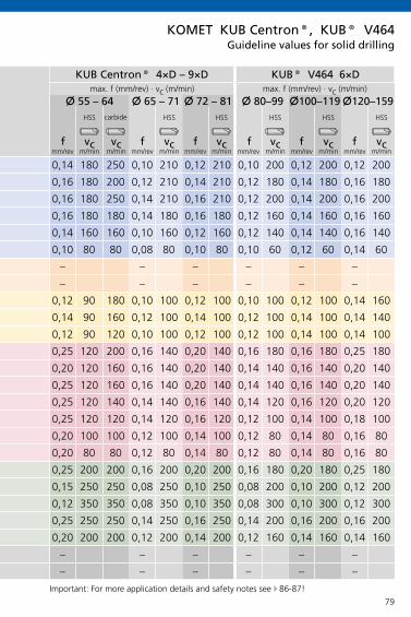
79
KOMET KUB Centron®, KUB® V464
KUB Centron® 4×D – 9×D KUB Centron® 4×D – 9×D KUB® V464 6×D
X 20 – 25 X 26 – 32 X 33 – 45 X 46 – 54 X 55 – 64 X 65 – 71 X 72 – 81 X 80–99 X100–119 X120–159HSS HSS HSS HSS HSS HSS HSS HSS HSS HSS
f vc vc f vc vc f vc vc f vc vc f vc vc f vc f vc f vc f vc f vcm/min m/min m/min m/min m/min m/min m/min m/min m/min m/min m/min m/min m/min m/min m/min
P
1.0
2.0
2.1
3.0
4.0
4.1
S
5.0
5.1
M
6.0
6.1
7.0
K
8.0
8.1
9.0
9.1
10.0
10.1
10.2
N
12.0
12.1
13.0
13.1
14.0
H
15.0
16.0
0,08 160 250 0,08 170 250 0,10 200 250 0,12 180 250 0,14 180 250 0,10 210 0,12 210 0,10 200 0,12 200 0,12 200
0,10 160 200 0,12 170 200 0,12 200 200 0,14 180 200 0,16 180 200 0,12 210 0,14 210 0,12 180 0,14 180 0,16 180
0,12 160 250 0,14 170 250 0,14 200 250 0,14 180 250 0,16 180 250 0,14 210 0,16 210 0,12 200 0,14 200 0,16 200
0,12 140 180 0,14 170 180 0,14 180 180 0,14 180 180 0,16 180 180 0,14 180 0,16 180 0,12 160 0,14 160 0,16 160
0,08 120 160 0,10 160 160 0,10 160 160 0,14 160 160 0,14 160 160 0,10 160 0,12 160 0,12 140 0,14 140 0,16 140
0,07 80 80 0,07 80 80 0,07 80 80 0,08 80 80 0,10 80 80 0,08 80 0,10 80 0,10 60 0,12 60 0,14 60
– – – – – – – – – –
– – – – – – – – – –
0,07 70 180 0,10 70 180 0,10 90 180 0,10 90 180 0,12 90 180 0,10 100 0,12 100 0,10 100 0,12 100 0,14 160
0,10 70 160 0,12 70 160 0,12 90 160 0,12 90 160 0,14 90 160 0,12 100 0,14 100 0,12 100 0,14 100 0,14 140
0,08 70 120 0,10 70 120 0,10 90 120 0,10 90 120 0,12 90 120 0,10 100 0,12 100 0,12 100 0,14 100 0,14 100
0,14 100 200 0,16 110 200 0,16 120 200 0,18 120 200 0,25 120 200 0,16 140 0,20 140 0,16 180 0,16 180 0,25 180
0,12 100 160 0,14 110 160 0,14 120 160 0,15 120 160 0,20 120 160 0,16 140 0,20 140 0,14 140 0,16 140 0,20 140
0,12 100 160 0,14 110 160 0,14 120 160 0,18 120 160 0,25 120 160 0,16 140 0,20 140 0,14 140 0,16 140 0,20 140
0,12 100 140 0,14 110 140 0,14 120 140 0,18 120 140 0,25 120 140 0,14 140 0,16 140 0,14 120 0,16 120 0,20 120
0,12 100 120 0,14 110 120 0,14 120 120 0,18 120 120 0,25 120 120 0,14 120 0,16 120 0,12 100 0,14 100 0,18 100
0,10 100 100 0,12 100 100 0,12 100 100 0,15 100 100 0,20 100 100 0,12 100 0,14 100 0,12 80 0,14 80 0,16 80
0,10 80 80 0,12 80 80 0,12 80 80 0,15 80 80 0,20 80 80 0,12 80 0,14 80 0,12 80 0,14 80 0,16 80
0,14 200 200 0,16 200 200 0,16 200 200 0,20 200 200 0,25 200 200 0,16 200 0,20 200 0,16 180 0,20 180 0,25 180
0,08 250 250 0,08 250 250 0,10 250 250 0,12 250 250 0,15 250 250 0,08 250 0,10 250 0,08 200 0,10 200 0,12 200
0,07 350 350 0,07 350 350 0,07 350 350 0,10 350 350 0,12 350 350 0,08 350 0,10 350 0,08 300 0,10 300 0,12 300
0,10 250 250 0,12 250 250 0,14 250 250 0,18 250 250 0,25 250 250 0,14 250 0,16 250 0,14 200 0,16 200 0,16 200
0,12 200 200 0,14 200 200 0,14 200 200 0,15 200 200 0,20 200 200 0,12 200 0,14 200 0,12 160 0,14 160 0,14 160
– – – – – – – – – –
– – – – – – – – – –
Guideline values for solid drilling
Important: For more application details and safety notes see E 86-87!
Mat
eria
l gro
upSe
lect
ion:
L.H
. fol
d pa
ge
max. feed f (mm/rev) · cutting speed vc (m/min) max. f (mm/rev) · vc (m/min) max. f (mm/rev) · vc (m/min)
carbide carbide carbide carbide carbide
mm/rev mm/rev mm/rev mm/rev mm/rev mm/rev mm/rev mm/rev mm/rev mm/rev

80
W29 .. W29 .. W29 ..
W29 .. W29 .. W29 ..
Chip Formation for various insert geometries
Tool: KUB Trigon® x 35 mm, 3×DMaterial: 42CrMo4V 1100 N/mm²Cutting data: vc = 200 m/min f = 0,16 mm/rev
Tool: KUB Trigon® x 35 mm, 3×DMaterial: structural steel St37Cutting data: vc = 300 m/min f = 0,12 mm/rev
Inserts suggested for KUB® and KUB Trigon®
Geometry 13 Geometry 13 Geometry 01 Geometry 03 Geometry 01 Geometry 01
internal external internal external internal external
Geometry 13 Geometry 13 Geometry 01 Geometry 03 Geometry 01 Geometry 01
internal external internal external internal external

81
W29 .. W29 .. W29 ..
W83 .. W83 .. W83 ..
Tool: KUB Trigon® x 40 mm, 3×DMaterial: stainless steel 1.4571Cutting data: vc = 140 m/min f = 0,1 mm/rev
Tool: KUB Quatron® x 35 mm, 3×DMaterial: 42CrMo4V 1100 N/mm²Cutting data: vc = 140 m/min f = 0,25 mm/rev
Inserts suggested for KUB® and KUB Trigon®
Inserts suggested for KUB Quatron®
Geometry 13 Geometry 13 Geometry 01 Geometry 03 Geometry 01 Geometry 01
internal external internal external internal external
Geometry 01 Geometry 21 Geometry 13 Geometry 13 Geometry 01 Geometry 01
internal external internal external internal external
Chip Formation for various insert geometries
Important: For more application details and safety notes see E 86-87!

82
5×D
§
§
$
&
$
$
&
X
§
&
X
KOMET KUB Duon®
Machining
solid drilling
blind hole
forge /casting skin, interface
angled start and drilling out, interrupted cut
convex
cross bore
centering bore, seam
chamber
stack plate drilling
rough boring
adjustable
Machining options
§ very good $ good & possible: see technical notes E 100 X not possible

83
H60 / H62
P
M
K
N
S
H
P
M
K
N
S
H
P
M
K
N
S
H
P
M
K
N
S
H
KOMET KUB Duon®
BK8440
BK2715
BK7710
BK84 / BK2715*
BK84
BK84
BK8125
BK8125
BK8125
Basic recommendation
alternative for better chip control
alternative for higher cutting speed
alternative for greater strength
Guideline values for solid drilling with KUB Duon® E 84
Insert selection H60 / H62
* for steels with tensile strength > 700 N/mm²

84
5×D
P
1.0
2.0
2.1
3.0
4.0
4.1
S
5.0
5.1
M
6.0
6.1
7.0
K
8.0
8.1
9.0
9.1
10.0
10.1
10.2
N
12.0
12.1
13.0
13.1
14.0
H
15.0
16.0
KOMET KUB Duon®
x 1
7,3
– 20
,7
x 2
0,8
– 29
,7
x 2
9,8
– 36
,2
x 3
6,3
– 44
,2
140 0,15 0,20 0,22 0,25
160 0,15 0,20 0,22 0,25
120 0,15 0,20 0,25 0,30
100 0,15 0,18 0,20 0,25
140 0,30 0,40 0,50 0,55
100 0,20 0,30 0,40 0,50
120 0,25 0,35 0,45 0,50
100 0,20 0,30 0,40 0,45
120 0,20 0,30 0,40 0,45
100 0,25 0,35 0,45 0,50
80 0,20 0,30 0,35 0,40
180 0,30 0,40 0,45 0,50
600 0,20 0,20 0,25 0,30
500 0,20 0,20 0,25 0,30
350 0,20 0,20 0,25 0,30
Mat
eria
l gro
upSe
lect
ion:
L.H
. fol
d pa
ge
Cut
ting
spee
d v c
(m/m
in)
max. feed f (mm/rev)
Guideline values for solid drilling
Important: For more application details and safety notes see E 86-87!

85
Z
x
Z
x
KOMET KUB Duon®
Short spot drills for KUB Duon® are fitted with standard H60… inserts.General note: Drill until the chamfer can be seen at the external bore diameter.
Method 1: Determining the centre depth Z
Size Centre depth Z1 2,7 mm2 3,3 mm3 4 mm4 4,7 mm5 6,5 mm
Method 2: Determining the centre dia.
Size Centre dia.1 17,3 mm2 20,8 mm3 24,8 mm4 29,8 mm5 36,5 mm
Application notes for pre-centering• from drilling depth > 5 × D (tools to customer requirement)• where drilling starts on surfaces which are angled or have not been pre-machined• where there are unstable conditions because of large tool overhang
for pre-centering from drilling depth > 5×D
External chamfer
Secondary cutting edge
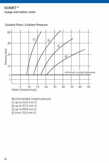
86
5 10 15 20 25 30 35 40 45
60
40
25
15
1
5
KOMET®
Coolant Flow / Coolant Pressure
Water (litres/minute)
Pres
sure
(bar
)
minimum coolant pressure
Recommended coolant pressure up to 22,9 mm x up to 37,0 mm x up to 69,9 mm x from 70,0 mm x
Usage and safety notes

87
KOMET®
Safety notes!
Important note: On exit of the drill a disc is ejected. With rotating components this can cause accidents. Please ar-range suitable guarding.
The technical notes provided in the application details depend on the environmental and application conditions (such as machine, environmental temperature, lubrication/coolant used and desired machining results): these are based on proper application conditions, use and compliance with the spindle speed limits given for the tools.
To prevent damage to machine and tool, we recommend that the drive power be calculated in advance (see performance calculation on page 21-25). The drive power which is actually available will be found in the machine manufacturer's spindle speed/performance diagram.
Safety equipment should be provided to protect personnel from flying chips.
To ensure the best possible tool life, the insert should be changed promptly.
Acceptable width of flank wear marks on inserts:W29 10... to W29 18... VB max = 0,20 mmW29 24... to W29 34... VB max = 0,25 mmW29 42... to W29 58... VB max = 0,30 mm
Usage and safety notes
Hazard warning:
If using tungsten carbide-based hard metal products together with cobalt as a binder metal, please read our safety data sheets, which are available for you to download from our website.http://www.kometgroup.com/navigation-top/download/service/datenblaetter.html

88
KOMET KUB® Drillmax, KUB® Drillmax XLTechnical notes
1. Starting on uneven surfaces (cast surfaces)• depending on the quality of the surface or when spot
drilling, reduce the feed
2. Starting on angled surfaces• spot face surface before starting bore
3. Angled bore exit• reduce feed by 50 % in the exit area
4. Starting on cambered surfaces• drilling on centre with reduced feed is possible• spot facing is required if the bore start point is outside the
radius centre
5. Drilling through a cross bore• half feed rate at interruption
6. Starting on a groove or large centering bore• end-face the seam or centre beforehand where applicable
(diameter min. 0.1 mm greater than drill diameter)• possible under certain conditions. Reduce feed where
necessary

89
KOMET KUB® Drillmax, KUB® Drillmax XLTechnical notes
Warning! A pilot hole must always be drilled. Direct spot drilling is not possible, even on a machined spot-drill surface. Angled surfaces or unmachined spot-drill surfaces must also be faced or spot faced for the pilot drilling tool.
7. Drilling a chamfer• not possible
8. Starting on an edge• not possible (start point must be flat)
9. Starting on a welded seam• spot face surface before starting bore
10. Drilling through stacked plates• good workpiece clamping required• avoid large spaces between elements• 12×D not possible
11. Roughing• 5×D and 7-8×D possible• 12×D, 20×D and 30×D not possible

90
KOMET KUB K2®Technical notes
1. Starting on uneven surfaces (cast surfaces)• depending on the quality of the surface or when spot
drilling, reduce the feed
2. Starting on angled surfaces• spot face surface before starting bore
3. Angled bore exit• reduce feed by 50 % in the exit area
4. Starting on cambered surfaces• not possible
5. Drilling through a cross bore• not possible
6. Starting on a groove or large centering bore• end-face the seam or centre beforehand where applicable
(diameter min. 0.1 mm greater than drill diameter)• possible under certain conditions. Reduce feed where
necessary
7. Drilling a chamfer• not possible
8. Starting on an edge• not possible (start point must be flat)

91
5-7±
1
x5-7±1
KOMET KUB K2®Technical notes
9. Starting on a welded seam• spot face surface before starting bore
10. Drilling through stacked plates• possible in principle• good workpiece clamping required• avoid large spaces between elements
11. Roughing• not possible
12. Coolant• internal coolant supply min. 5 bar
13. Rotating application• max. concentricity in rotating application 0,05 mm
14. Stationary application• max. offset in stationary application 0,025 mm
Recommended pilot hole • basic body from 5×D: for the material group 1.0

92
2×D
1. Starting on uneven surfaces (cast surfaces)• subject to the surface, reduce feed as required when
starting the bore
2. Starting on angled surfaces• subject to the starting angle, the feed must be reduced
when starting the bore. Rule of thumb: 3° 30%; 10° 40%; 25° 60% use
tools max. 2×D• use tough insertand stable corner radius
3. Angled bore exit• from wear cut is interrupted reduce feed rate up to 50%• use tough insertand stable corner radius
4. Starting on cambered surfaces• no problems• reduce feed rate if necessary
5. Drilling through a cross bore• reduce feed rate 50% if necessary• watch for chip jamming around tool• use tough insertand stable corner radius
6. Starting on a groove or large centering bore• use short tools, max. 3×D• spot face if required• reduce feed• use tough insert for internal cutting edge
Technical notesKOMET KUB Quatron®, KUB Trigon®, KUB® Drill

93
2×D
7. Drilling a chamber• first bore Nos. 1 + 2, then bore No. 3• check distribution is symmetrical• avoid chip jams• if necessary reduce to approx. 1-1,5 mm in the x on
circumference• reduce feed rate 50% for interrupted cut• use tough insertand stable corner radius
8. Starting on an edge• reduce feed rate by 50%• use tough insertand stable corner radius
9. Starting on a welded seam• reduce feed rate• use max. 3×D tools
10. Drilling through stacked plates• possible with KUB Quatron®• not possible with KUB® / KUB Trigon®• good workpiece clamping required• max. gap = 1 mm
11. Roughing• possible with KUB Quatron®• possible with KUB Trigon® up to 3×D
12. Adjustable• using adjusting device (ABS-MV) and eccentric adjusting
device• for turning machines over axisNote: please note max. offset x in tables
KOMET KUB Quatron®, KUB Trigon®, KUB® DrillTechnical notes

94
3×D
1. Starting on uneven surfaces (cast surfaces)• subject to the surface, reduce feed as required when
starting the bore
2. Starting on angled surfaces• max. 3° angled position possible (cast angles)• reduce feed rate when starting bore• use stable corner radius
3. Angled bore exit• from wear cut is interrupted reduce feed rate up to 50%• use tough insertand stable corner radius
4. Starting on cambered surfaces• no problems• reduce feed rate if necessary
5. Drilling through a cross bore• reduce feed rate 50% if necessary• watch for chip jamming around tool• use tough insertand stable corner radius
6. Starting on a groove or large centering bore• use short tools, max. 3×D• spot face if required• reduce feed• use tough insert for internal cutting edge
Technical notesKOMET KUB Quatron®, KUB Trigon®, KUB® Drill

95
3×D
7. Drilling a chamber• first bore Nos. 1 + 2, then bore No. 3• check distribution is symmetrical• avoid chip jams• if necessary reduce to approx. 1-1,5 mm in the x on
circumference• reduce feed rate 50% for interrupted cut• use tough insertand stable corner radius
8. Starting on an edge• not possible for 3×D tools• because of the undefined surface for starting the bore,
pre-machining is required (spot facing, face milling)• then continue as described under Point 1
9. Starting on a welded seam• reduce feed rate• use max. 3×D tools
10. Drilling through stacked plates• possible with KUB Quatron® • not possible with KUB® / KUB Trigon® • good workpiece clamping required
11. Roughing• possible with KUB Quatron® • possible with KUB Trigon® up to 3×D
12. Adjustable• using adjusting device (ABS-MV) and eccentric adjusting
device• for turning machines over axisNote: please note max. offset x in tables
KOMET KUB Quatron®, KUB Trigon®, KUB® DrillTechnical notes

96
4×D
1. Starting on uneven surfaces (cast surfaces)• subject to the surface, reduce feed as required when
starting the bore
2. Starting on angled surfaces• not possible for 4×D tools• starting surface must be spot faced or spot milled
3. Angled bore exit• Reduce feed by up to 50% for 4×D tools
4. Starting on cambered surfaces• starting surface must be milled evenly
5. Drilling through a cross bore• not possible with 4×D tools• if necessary apply cross bore later
6. Starting on a groove or large centering bore• points for starting bore must be rough machined first
Technical notesKOMET KUB Trigon®, KUB® Drill

97
4×D
7. Drilling a chamber• not possible
8. Starting on an edge• not possible for 4×D tools• because of the undefined surface for starting the bore,
pre-machining is required (spot facing, face milling)• then continue as described under Point 1
9. Starting on a welded seam• Reduce feed by up to 50% for 4×D tools• if necessary pre-machine point for starting bore
10. Drilling through stacked plates• not possible
11. Roughing• not possible
12. Adjustable• dimensional adjustment within 1/10 range possible
KOMET KUB Trigon®, KUB® DrillTechnical notes

98
KOMET KUB Pentron®Technical notes
1. Starting on uneven surfaces (cast surfaces)• when inserting and withdrawing the drill, reduce the
feed rate by approx. 30-50% (depending on component stability, clamping and surface quality)
2. Starting on angled surfaces / angled bore exit• when inserting the drill, reduce the feed rate by approx.
30-60% until full diameter is reached • when withdrawing the drill after interruption to the cut,
reduce the feed rate by approx. 30-60%• use tough insert and stable corner radius
3. Starting on cambered surfaces• when inserting the drill, reduce the feed rate by approx.
30-60% until full diameter is reached• when withdrawing the drill after interruption to the cut,
reduce the feed rate by approx. 30-60% (depending on component stability and clamping).
4. Drilling through a cross bore• when inserting and withdrawing the drill, reduce the
feed rate by approx. 30-50% (depending on component stability, clamping and surface quality)
• in the vicinity of the cross bore, reduce the feed rate by 50%
• watch for chip jamming around tool• use tough insert and stable corner radius
5. Starting on a groove or large centering bore• when inserting the drill, reduce the feed rate by approx.
30-50% until centring depth is reached• reduce feed rate• use tough insert for internal cutting edge• spot face if required

99
KOMET KUB Pentron®
Technical notes
6. Drilling a chamber• first bore Nos. 1 + 2, then bore No. 3• check distribution is symmetrical• avoid chip jams• use tough insertand stable corner radius• Continuous drilling: when inserting the drill, reduce the
feed rate by approx. 30-60% (depending on component stability and clamping)
• Interruption to cut: when drilling the cut interruption, reduce the feed rate by approx. 50-60%
7. Starting on an edge• when inserting and withdrawing the drill, reduce the
feed rate by approx. 30-50% (depending on component stability, clamping and surface quality)
• use tough insert and stable corner radius
8. Starting on a welded seam• when inserting the drill, reduce the feed rate by approx.
30-60% until full diameter is reached• when withdrawing the drill after interruption to the cut,
reduce the feed rate by approx. 30-60% (depending on component stability and clamping).
9. Drilling through stacked plates• good workpiece clamping required• max. gap = 1 mm
10. Roughing• not possible
11. Adjustable• when inserting and withdrawing the drill reduce the feed
rate by approx. 30-50% until full bore diameter is reached (depending on component stability and clamping).
• use tough insert and stable corner radius

100
KOMET KUB Duon®
1. Starting on uneven surfaces (cast surfaces)• Possible in principle• Reduce feed rate when starting bore
2. Starting on angled surfaces• Spot face surface before starting bore• Avoid chips jams
3. Angled bore exit• Possible under certain conditions• Reduce feed rate if necessary
4. Starting on cambered surfaces• Centered boring can be started with reduced feed rate• Spot facing is required if the point for starting the bore
is outside the radius centre
5. Drilling through a cross bore• Halve feed rate at interruption• Cross bore max. 1/3 of bore diameter• Off-centre cross bore not possible
6. Starting on a groove or large centering bore• Possible under certain conditions• Reduce feed rate if necessary• Face beforehand where centre is particularly large
Technical notes

101
KOMET KUB Duon®
7. Drilling a chamber• not possible
8. Starting on an edge• Start point must be flat
9. Starting on a welded seam• Reduce feed rate when starting bore• Face beforehand if necessary
10. Drilling through stacked plates• Possible in principle• Avoid large spaces between elements
11. Roughing• not possible
12. Adjustable• not possible• dimensional adjustment of diameter by means of inserts
Technical notes

102
KOMET KUB Centron® Powerline
1. Starting on uneven surfaces (cast surfaces)• possible in principle• reduce feed rate when starting bore
2. Starting on angled surfaces• surface for starting bore must be spot faced beforehand• avoid chip jams on drill shank
3. Angled bore exit• possible under certain conditions• reduce feed rate if necessary• drilling angle max. 3°
4. Starting on cambered surfaces• centered boring can be started with reduced feed rate• spot facing is required if the point for starting the bore is
outside the radius centre
5. Drilling through a cross bore• halve feed rate at interruption• cross bore max. 1/3 of bore diameter• off-centre cross bore not possible
6. Starting on a groove or large centering bore• surface for starting bore must be spot faced beforehand• reduce feed rate if necessary
Technical notes

103
KOMET KUB Centron® Powerline
7. Drilling a chamber• not possible
8. Starting on an edge• not possible• surface for starting bore must be spot faced beforehand• avoid chip jams on drill shank
9. Starting on a welded seam• reduce feed rate when starting bore• face beforehand if necessary
10. Drilling through stacked plates• not possible
11. Backing out of the bore• tool 9×D swings up at bore exit• back out of the bore with greatly reduced speed to avoid
any development of chatter marks
12. adjustable• not adjustable, fixed diameter• intermediate dimensions on request
Technical notes

104
KOMET KUB Centron®
1. Starting on uneven surfaces (cast surfaces)• Possible in principle• Reduce feed rate when starting bore
2. Starting on angled surfaces• Surface for starting bore must be spot faced beforehand• Avoid chip jams on drill shank
3. Angled bore exit• Possible under certain conditions• Reduce feed rate if necessary• Drilling angle max. 3°
4. Starting on cambered surfaces• Centered boring can be started with reduced feed rate• Spot facing is required if the point for starting the bore
is outside the radius centre
5. Drilling through a cross bore• Halve feed rate at interruption• Cross bore max. 1/3 of bore diameter• Off-centre cross bore not possible
6. Starting on a groove or large centering bore• Possible under certain conditions• Reduce feed rate if necessary• Face beforehand where centre is particularly large• Central drill bit basic adjustment optimize if necessary
Technical notes

105
KOMET KUB Centron®
7. Drilling a chamber• not possible
8. Starting on an edge• Surface for starting bore must be spot faced beforehand• Avoid chip jams on drill shank
9. Starting on a welded seam• Reduce feed rate when starting bore• Face beforehand if necessary
10. Drilling through stacked plates• not possible
11. Blind hole• possible• set guide pads 0.5 mm below actual x
12. Adjustable• can be adjusted from 65 mm diameter
Technical notes

106
Problems possible causes solutions
Ro
tati
ng
an
d s
tati
on
ary
use
Short tool life types of wear on inserts• cutting speed to high select correct cutting speed• cutting material with too little wear resistance select
grade with higher wear resistance• tool overhang too great if possible use shorter tool• damaged insert seating check tool, change if
necessary• clamping device not stable enough improve stability
Bore narrows at bottom• chip jam on external cutting edge use different chip
fracture geometry, increase feed if necessary• material very soft increase cutting speed, reduce
feed. Use positive chip geometry
Bore widens at bottom• chip jam on internal cutting edge use different chip
fracture geometry, increase feed if necessary
Bad surface finish• bad chip removal improve cutting parameters:
increase cutting speed reduce feed
Bild up on cutting edge• cutting speed too low increase cutting speed• insert too negative use positive geometry• coating not suitable select correct coating
Friction marks on tool shank• bore diameter too small check setting• chip removal problems improve cutting parameters,
check geometry of inserts• cutting edge corner radius too large use correct
cutting edge radius
KOMET KUB Quatron®, KUB Trigon®, KUB® Drill

107
Ro
tati
ng
use
Fracture on internal cutting edge• drill bit height of tool too high/too low tool turret/
holder may have shifted. Readjust machine• mix-up between renforced/non renforced insert
use correct insert• feed rate too high reduce feed rate• insert grade too brittle use tougher insert grade• wrong insert geometry use geometry with
chamfered cutting edge
Fracture on external cutting edge• feed rate too high reduce feed rate• interrupted cut change to tougher insert grade• cutting edge corner radius too small use insert
with larger cutting edge radius
Bore too small/ too large• machine not at X-0 position move axis to correct
position• machine axis shifted readjust machine
Fracture on internal cutting edge• mix-up between renforced/non renforced insert
use correct insert• feed rate too high reduce feed rate• insert grade too brittle use tougher insert grade• wrong insert geometry use geometry with
chamfered cutting edge
Fracture on external cutting edge• feed rate too high reduce feed rate• interrupted cut change to tougher insert grade• cutting edge corner radius too small use insert
with larger cutting edge radius
Bore too small/ too large with adjustable tool• wrong cutting edge radius used use correct cut-
ting edge radius• setting wrong correct setting
Stat
ion
ary
use
KOMET KUB Quatron®, KUB Trigon®, KUB® DrillProblems possible causes solutions
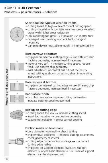
108
KOMET KUB Centron®
Short tool life types of wear on inserts• cutting speed to high select correct cutting speed• cutting material with too little wear resistance select
grade with higher wear resistance• tool overhang too great if possible use shorter tool• damaged insert seating check tool, change if
necessary• clamping device not stable enough improve stability
Bore narrows at bottom• chip jam on external cutting edge use different chip
fracture geometry, increase feed if necessary• material very soft increase cutting speed, reduce
feed. Use positive chip geometry• axial adjustment of central drill bit not the best >
adjust setting as shown on setting sheet in operating instructions
Bore widens at bottom• chip jam on internal cutting edge use different chip
fracture geometry, increase feed if necessary
Bad surface finish• bad chip removal improve cutting parameters:
increase cutting speed reduce feed
Bild up on cutting edge• cutting speed too low increase cutting speed• insert too negative use positive geometry• coating not suitable select correct coating
Friction marks on tool shank• bore diameter too small check setting• chip removal problems improve cutting parameters,
check geometry of inserts• cutting edge corner radius too large use correct
cutting edge radius• chip jams on support element, fractured support
element > where basic element < 6 × D use of support element can be dispensed with
Problems possible causes solutions
Ro
tati
ng
an
d s
tati
on
ary
use

109
KOMET KUB Centron®
Heavy wear on one side on central drill bit• tool not central tool turret/holder may have shif-
ted – readjust machine
Withdrawal groove on one side• tool not central tool turret/holder may have shif-
ted – readjust machine
Fracture on external cutting edge• feed rate too high reduce feed rate• interrupted cut change to tougher insert grade• cutting edge corner radius too small use insert
with larger cutting edge radius
Bore too small/ too large• machine not at X-0 position move axis to correct
position• machine axis shifted readjust machine
Heavy wear on one side on central drill bit• insufficient guiding check length setting on cen-
tral drill bit
Fracture on external cutting edge• feed rate too high reduce feed rate• interrupted cut change to tougher insert grade• cutting edge corner radius too small use insert
with larger cutting edge radius
Bore too small/ too large with adjustable tool• wrong cutting edge radius used use correct cut-
ting edge radius• setting wrong correct setting
Problems possible causes solutionsR
ota
tin
g u
seSt
atio
nar
y u
se

110
KOMET KUB Duon®
Short tool life types of wear on inserts
• cutting speed to high select correct cutting speed
• cutting material with too little wear resistance select grade with higher wear resistance
• tool overhang too great if possible use shorter tool
• damaged insert seating check tool, change if necessary
• clamping device not stable enough improve stability
• run-out error check tool, adaptor and spindle
Bad surface finish
• chip jam on external cutting edge improve cutting parameters: increase cutting speed
reduce feed check cutting parameters: reduce feed rate when
starting bore
Friction marks on tool shank
• bore diameter too small check setting
• chip removal problems improve cutting parameters, check geometry of
inserts
Problems possible causes solutions

111
KOMET KUB Duon®
Wear
• cutting material not sufficiently wear resistant better wear resistant material
• cutting speed too high reduce cutting speed
• run-out error check tool, adaptor and spindle
Wear, micro fractures
• cutting material too hard use tougher cutting material with higher tensile
strength
• feed rate not reduced when starting bore reduce feed rate when starting bore and drilling
out
• run-out error check tool, adaptor and spindle
Securing the inserts
• wrong screwdriver used only use TorxPlus® screws and screwdriver
• starting torque too low Check starting torques. Optimum starting torques
only possible with TorxPlus®
Problems possible causes solutions

112
KUB Trigon® · KUB®
x D A
25,0 – 27,9 0,08
28,0 – 28,9 0,09
29,0 – 29,9 0,10
30,0 – 31,9 0,08
32,0 – 33,9 0,09
34,0 – 36,9 0,10
37,0 – 38,9 0,08
39,0 – 41,9 0,09
42,0 – 44,9 0,10
x D
R0,
4
x D
R0,
8
R0,8
R0,4
A
KUB Centron®
x D A33,0 – 37,9 0,0838,0 – 54,9 0,0955,0 – 64,9 0,10
DR0,8 = DR0,4 – 2 × A
KOMET KUB Trigon®, KUB Centron®
KUB K2® H70 H70 H71 H72
x D
a BK8425 BK2725 BK2725 BK7930
x D a a10,0 – 10,9 2,1 2,611,0 – 11,9 2,3 2,812,0 – 12,9 2,45 3,113,0 – 13,9 2,6 3,314,0 – 14,9 2,8 3,615,0 – 15,9 3,0 3,816,0 – 16,9 3,2 4,017,0 – 17,9 3,4 4,318,0 – 18,9 3,5 4,519,0 – 20,5 3,8 4,8
KOMET KUB K2®
Dimensional variation
Starting/roughing sizes

113
KUB Trigon®
x D
a
x D a14,0 – 19,5 1,320,0 – 24,0 1,524,5 – 36,0 1,737,0 – 44,0 2,045,0 – 54,0 2,455,0 – 68,0 2,769,0 – 82,0 3,5
KUB Quatron® / KUB Pentron®
x D
a
x D a14,0 – 17,5 1,518,0 – 21,0 1,922,0 – 26,5 2,427,0 – 33,0 2,834,0 – 44,0 3,045,0 – 52,0 3,353,0 – 65,0 3,7
x D a17,3 4,017,5 4,118,0 4,118,5 4,219,0 4,319,5 4,420,0 4,520,5 4,521,0 4,821,5 4,922,0 5,0
x D
aKUB Duon® x D a28,0 6,128,5 6,229,0 6,329,5 6,430,0 6,731,5 6,731,0 6,831,5 6,932,0 7,032,5 7,133,0 7,133,5 7,234,0 7,334,5 7,435,0 7,535,5 7,536,0 7,6
x D a22,5 5,123,0 5,123,5 5,224,0 5,324,5 5,425,0 5,725,5 5,726,0 5,826,5 5,927,0 6,027,5 6,1
x D a36,5 7,737,0 8,037,5 8,138,0 8,138,5 8,239,0 8,339,5 8,440,0 8,540,5 8,541,0 8,641,5 8,742,0 8,842,5 8,943,0 8,943,5 9,044,0 9,144,2 9,2
KOMET KUB Quatron®, KUB Pentron®, KUB Trigon®, KUB Duon®Starting/roughing sizes
Important: For more application details and safety notes see E 86-87!

114
KO
MET
Tw
inK
om
® G
01
KO
MET
Tw
inK
om
® G
01
KO
MET
Tw
inK
om
® G
01
KO
MET
Tw
inK
om
® G
01
KO
MET
Tw
inK
om
® G
04
E 116 – 117 E 116 – 117 E 116 – 117
E 119 E 118 E 118 E 119 E 119
E 120 E 121 E 120 E 120
E 122 E 122 E 122 E 122 E 122
E 123 E126 E 128 E 123 E 123
E 124 – 125 E 127 E 129 E 124 – 125 E 124 – 125
E 64 – 65 E 48 – 49 E 144 – 146 E 64 – 65 E 64 – 65
E 133 E 133 E 133
E 130 E 130 E 130
E 131 E 131 E 131
E 132
Index Roughing
Construction, operating instruction
Optimum cutting depth range ap
Surface quality results
Machining options
Insert selection
Guideline values: cutting speed vcfeed fz
Guideline values: higher cutting speed vcinsert coating
Chip formation
Technical notes
ProblemPossible causes – Solutions
Overhang length

115
KO
MET
Tw
inK
om
® G
01
KO
MET
Tw
inK
om
® G
01
KO
MET
Tw
inK
om
® G
01
KO
MET
Tw
inK
om
® G
01
KO
MET
Tw
inK
om
® G
04
E 116 – 117 E 116 – 117 E 116 – 117
E 119 E 118 E 118 E 119 E 119
E 120 E 121 E 120 E 120
E 122 E 122 E 122 E 122 E 122
E 123 E126 E 128 E 123 E 123
E 124 – 125 E 127 E 129 E 124 – 125 E 124 – 125
E 64 – 65 E 48 – 49 E 144 – 146 E 64 – 65 E 64 – 65
E 133 E 133 E 133
E 130 E 130 E 130
E 131 E 131 E 131
E 132
Index Roughing

116
KOMET TwinKom® G01
Insert seating
Scale
Setting the diameter
Length adjustment screw Clamping screw
Length adjustment screw
Basic body
Holder
Clamping screw only required for twin cutter with axial adjustment
Insert seating
Adaptors with the same approach angle can be combined among each other.
Adjusting pin Clamping plate
Clamping screw for clamping plate
Clamping screw for insert
Construction

117
KOMET TwinKom® G01
d1d2
ap
d
D
fz
D
a p m
ax
d = 100 –100 – 80
2[( )+ 3]× 0,8
d = 89,6 mm
finishedof
fset
Example:
Dfinished = 100 mm
Dblank = 80 mm
Offset = 3 mm
Distribution of cut For burnt-out and pre-cast bores with large allowances.
d = Dfinished –Dfinished – Dblank
2[( )+ offset]× 0,8
Combination roughing / combination finishingWith combination roughing and combination finish-ing, division of the whole cutting width is produced by offsetting the cutting edge axially and radially. This should allow the ensuing cutting forces to be better distributed and produce an even cutting result. With the roughing operation, this allows double the cutting width (using only a single feed
Length adjustmentLoosen insert seating and then tighten again slightly. Set length to 0.02 mm in front of required dimension using length adjustment screw , tighten insert seating and set to required height with length adjustment screw . Repeat the same procedure on the second side.
Setting the diameterLoosen the clamping screw on one side only. Set the diameter and tighten clamping screw again. Repeat the same procedure on the second side. The scale is used purely for coarse setting the diameter. Exact diameter setting should be carried out with a setting device.
blan
k
Operating instruction
rate f=fz). With the finishing operation, the cutting width is divided so that some of the intermediate machining can be omitted.

118
KOMET TwinKom® G01
0,20
0,15
0,10
0,05
1 2 30,5 1,5 2,5
W30 04120.02
W30 14120.04
W30 26120.05
0,40
0,35
0,30
0,25
0,20
0,15
0,10
0,05
1 2 3 4 5 6 7 8 9 10 11
SOEX06
SOEX12
SOEX07
SOEX09
Cutting depth ap (mm)
Feed
fz
(mm
/too
th)
Optimum cutting depth range
optimum range
Guideline values for medium strength steels
Cutting depth ap (mm)
Feed
fz
(mm
/too
th)
optimum range
Important: For more application details and safety notes see E 86-87!

119
KOMET TwinKom® G01
0,40
0,35
0,30
0,25
0,20
0,15
0,10
0,05
1 2 3 4 5 6 7 8 9 10 11
W29 10
W29 18
WOEX12W29 58 WOEX10
W29 50 WOEX08 W29 42
WOEX05W29 24
WOEX06W29 34
0,40
0,35
0,30
0,25
0,20
0,15
0,10
0,05
0,5 1 1,5 2 2,5 3
W29 34160..
W29 24160..
W29 18160..
W29 10150..W29 18150..
W29 34150..W29 24150..
W29 42150..
Cutting depth ap (mm)
Feed
fz
(mm
/too
th)
optimum range
Guideline values for geometry 15 and 16 for medium strength steels
Cutting depth ap (mm)
Feed
fz
(mm
/too
th)
Guideline values for medium strength steels
Optimum cutting depth range

120
Ra
fn
Ra2
W29..16
iper
W29..15
iper
KOMET TwinKom® G01
fn
3,5
3,0
2,5
2,0
1,5
1,0
0,5
00,1 0,2 0,3
iperiper
iper
Ave
rage
sur
face
qua
lity
R a (µ
m)
Feed f (mm)
Geometry 16 Geometry 15
Comparison of surface quality results for "Wiper" – R04 for = 90° (in X40Cr13 / 1.4034)
Surface quality results

121
Ra
fn
Ra2
W57..18 W57..14
iper
iper
KOMET TwinKom® G01
fn
1,75
1,50
1,25
1,00
0,75
0,50
0,25
00,05 0,10 0,15
iper iperiper
Comparison of surface quality results for "Wiper" – R04 for = 90° (in X40Cr13 / 1.4034)
Surface quality resultsA
vera
ge s
urfa
ce q
ualit
y R a
(µm
)
Feed f (mm)
Geometry 18 Geometry 14
Important: For more application details and safety notes see E 86-87!
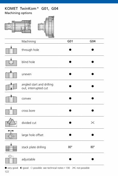
122
G01 G04
§ §
§ §
§ §
§ §
§ §
§ §
§ X
§ §
80° 80°
§ §
KOMET TwinKom® G01, G04
Machining
through hole
blind hole
uneven
angled start and drilling out, interrupted cut
convex
cross bore
divided cut
large hole offset
stack plate drilling
adjustable
Machining options
§ very good $ good & possible: see technical notes E 130 X not possible

123
W01 W29..01 W29..02 W29..03 W29..11 W29..13 W29..15 W29..16
P
MKN
S
H
P
MKN
S
H
P
MKN
S
H
P
MKN
S
H
P
MKN
S
H
KOMET TwinKom®
BK8425BK77
BK7930BK7615
BK77
BK8425 BK6440 BK8425 BK8425 BK8430K10
BK79 BK73
K10
BK6425 BK72 BK6440 BK6425 BK7325 BK73
BK72 BK7325 BK73CBN57/SK45 BK7615 PKD55 BK50
P40
P40K10 K10
K10
BK8430
BK73BK60
Basic recommendation
alternative for better chip control
alternative for higher cutting speed E 64 - 65
alternative for greater strength
for better surface finish
Insert selection W01, W29

124
W29..00, ..01, ..02, ..03, ..11, ..13 W29..15, W29..16
P
1.0
2.0
2.1
3.0
4.0
4.1
S
5.0
5.1
M
6.0
6.1
7.0
K
8.0
8.1
9.0
9.1
10.0
10.1
10.2
N
12.0
12.1
13.0
13.1
14.0
H
15.0
16.0
KOMET TwinKom®
W29 10
ap= 1,5
W29 18
ap= 2,5
W29 24
ap= 4,5
W29 34
ap= 6
W29 42
ap= 7,5
W29 50
ap= 9
W29 58
ap= 9
W29 10
ap= 1
W29 18
ap= 1,5
W29 24
ap= 2
W29 34
ap= 2
W29 42
ap= 2,5
200 0,10 0,12 0,15 0,20 0,25 0,30 0,30 0,06 0,10 0,18 0,18 0,25
200 0,10 0,12 0,15 0,20 0,25 0,30 0,30 0,06 0,10 0,18 0,18 0,25
180 0,10 0,12 0,15 0,20 0,25 0,30 0,30 0,06 0,10 0,18 0,18 0,25
140 0,10 0,12 0,15 0,20 0,25 0,30 0,30 0,06 0,10 0,18 0,18 0,25
120 0,06 0,10 0,12 0,15 0,20 0,25 0,25 0,06 0,10 0,18 0,18 0,25
50 0,06 0,08 0,10 0,12 0,15 0,18 0,20
50 0,06 0,08 0,10 0,12 0,15 0,18 0,20
120 0,07 0,09 0,12 0,12 0,15 0,20 0,20 0,06 0,09 0,15 0,15 0,20
120 0,07 0,09 0,12 0,12 0,15 0,20 0,20 0,06 0,09 0,15 0,15 0,20
90 0,05 0,07 0,10 0,10 0,12 0,15 0,15 0,06 0,09 0,15 0,15 0,20
180 0,12 0,15 0,25 0,25 0,30 0,35 0,35
140 0,12 0,15 0,25 0,25 0,30 0,35 0,35
140 0,12 0,15 0,25 0,25 0,30 0,35 0,35
120 0,10 0,12 0,15 0,20 0,25 0,30 0,35
100 0,10 0,12 0,15 0,20 0,25 0,30 0,35
100 0,10 0,12 0,15 0,20 0,25 0,30 0,35
90 0,12 0,15 0,25 0,30 0,30 0,35 0,35
250 0,12 0,15 0,25 0,25 0,30 0,35 0,35
250 0,12 0,15 0,25 0,25 0,30 0,35 0,35
250 0,12 0,15 0,25 0,25 0,30 0,35 0,35
250 0,12 0,15 0,25 0,25 0,30 0,35 0,35
200 0,12 0,15 0,25 0,25 0,30 0,35 0,35
Mat
eria
l gro
upSe
lect
ion:
L.H
. fol
d pa
ge
Cut
ting
spee
d v c
(m/m
in)
max. feed fz (mm/tooth) max. feed fz (mm/tooth)
Guideline values for roughing with W29

125
W29..00, ..01, ..02, ..03, ..11, ..13 W29..15, W29..16
P
1.0
2.0
2.1
3.0
4.0
4.1
S
5.0
5.1
M
6.0
6.1
7.0
K
8.0
8.1
9.0
9.1
10.0
10.1
10.2
N
12.0
12.1
13.0
13.1
14.0
H
15.0
16.0
KOMET TwinKom®
W29 10
ap= 1,5
W29 18
ap= 2,5
W29 24
ap= 4,5
W29 34
ap= 6
W29 42
ap= 7,5
W29 50
ap= 9
W29 58
ap= 9
W29 10
ap= 1
W29 18
ap= 1,5
W29 24
ap= 2
W29 34
ap= 2
W29 42
ap= 2,5
200 0,10 0,12 0,15 0,20 0,25 0,30 0,30 0,06 0,10 0,18 0,18 0,25
200 0,10 0,12 0,15 0,20 0,25 0,30 0,30 0,06 0,10 0,18 0,18 0,25
180 0,10 0,12 0,15 0,20 0,25 0,30 0,30 0,06 0,10 0,18 0,18 0,25
140 0,10 0,12 0,15 0,20 0,25 0,30 0,30 0,06 0,10 0,18 0,18 0,25
120 0,06 0,10 0,12 0,15 0,20 0,25 0,25 0,06 0,10 0,18 0,18 0,25
50 0,06 0,08 0,10 0,12 0,15 0,18 0,20
50 0,06 0,08 0,10 0,12 0,15 0,18 0,20
120 0,07 0,09 0,12 0,12 0,15 0,20 0,20 0,06 0,09 0,15 0,15 0,20
120 0,07 0,09 0,12 0,12 0,15 0,20 0,20 0,06 0,09 0,15 0,15 0,20
90 0,05 0,07 0,10 0,10 0,12 0,15 0,15 0,06 0,09 0,15 0,15 0,20
180 0,12 0,15 0,25 0,25 0,30 0,35 0,35
140 0,12 0,15 0,25 0,25 0,30 0,35 0,35
140 0,12 0,15 0,25 0,25 0,30 0,35 0,35
120 0,10 0,12 0,15 0,20 0,25 0,30 0,35
100 0,10 0,12 0,15 0,20 0,25 0,30 0,35
100 0,10 0,12 0,15 0,20 0,25 0,30 0,35
90 0,12 0,15 0,25 0,30 0,30 0,35 0,35
250 0,12 0,15 0,25 0,25 0,30 0,35 0,35
250 0,12 0,15 0,25 0,25 0,30 0,35 0,35
250 0,12 0,15 0,25 0,25 0,30 0,35 0,35
250 0,12 0,15 0,25 0,25 0,30 0,35 0,35
200 0,12 0,15 0,25 0,25 0,30 0,35 0,35
Mat
eria
l gro
upSe
lect
ion:
L.H
. fol
d pa
ge
Cut
ting
spee
d v c
(m/m
in)
max. feed fz (mm/tooth) max. feed fz (mm/tooth)
Guideline values for roughing with W29
Important: For more application details and safety notes see E 86-87!

126
W83..01 W83..13 W83..21
-01 -13 -21
P
M
K
N
S
H
P
M
K
N
S
H
P
M
K
N
S
H
P
M
K
N
S
H
KOMET TwinKom®
BK8425
BK7710
BK7935
BK7615
BK7710
BK8425 BK8430
BK7935 BK2730
BK6420 / BK6115 BK6130
BK74
BK6115 BK6130
BK8430
BK8430
Basic recommendation
alternative for better chip control
alternative for higher cutting speed E 48 - 49
alternative for greater strength
Insert selection W83

127
W83..01, W83..13, W83..21
P
1.0
2.0
2.1
3.0
4.0
4.1
S
5.0
5.1
M
6.0
6.1
7.0
K
8.0
8.1
9.0
9.1
10.0
10.1
10.2
N
12.0
12.1
13.0
13.1
14.0
H
15.0
16.0
KOMET TwinKom®
W83 13...
ap= 1,5
W83 18...
ap= 2,5
W83 23...
ap= 4,5
W83 32...
ap= 4,5
W83 44...
ap= 7,5
200 0,12 0,14 0,20 0,25 0,35
200 0,12 0,14 0,20 0,25 0,35
180 0,12 0,14 0,20 0,25 0,35
140 0,12 0,14 0,20 0,25 0,35
120 0,10 0,12 0,18 0,25 0,3
50 0,08 0,10 0,15 0,20 0,25
50 0,08 0,10 0,15 0,20 0,25
120 0,10 0,12 0,18 0,25 0,30
120 0,10 0,12 0,18 0,25 0,30
90 0,10 0,12 0,18 0,25 0,30
180 0,15 0,20 0,25 0,35 0,50
140 0,15 0,20 0,25 0,35 0,50
140 0,15 0,20 0,25 0,35 0,50
120 0,15 0,20 0,25 0,35 0,50
100 0,12 0,15 0,20 0,25 0,40
100 0,12 0,15 0,20 0,25 0,40
90 0,15 0,20 0,25 0,30 0,40
250 0,15 0,20 0,25 0,35 0,50
250 0,15 0,20 0,25 0,35 0,50
250 0,15 0,20 0,25 0,35 0,50
250 0,15 0,20 0,25 0,35 0,50
200 0,15 0,20 0,25 0,35 0,50
Mat
eria
l gro
upSe
lect
ion:
L.H
. fol
d pa
ge
Cut
ting
spee
d v c
(m/m
in)
max. feed fz (mm/tooth)
Guideline values for roughing with W83
Important: For more application details and safety notes see E 86-87!

128
W30 W30 PKD/CBN W57..12 W57..14
P
M
K
N
S
H
P
M
K
N
S
H
P
M
K
N
S
H
P
M
K
N
S
H
KOMET TwinKom®
BK8430
K10
BK8430
BK7615
K10
CBN40 >52HRC
CK32 / BK6425
CK32 / BK6425
CK3210 / BK60
BK7710
CK3210 / BK60
CBN57
PKD55 BK7710
BK6425
BK6425
Basic recommendation
alternative for better chip control
alternative for higher cutting speed E 144 - 146
alternative for greater strength
Insert selection W30, W57

129
W30, W57
P
1.0
2.0
2.1
3.0
4.0
4.1
S
5.0
5.1
M
6.0
6.1
7.0
K
8.0
8.1
9.0
9.1
10.0
10.1
10.2
N
12.0
12.1
13.0
13.1
14.0
H
15.0
16.0
KOMET TwinKom®
W30 04...W57 04...
ap= 0,15
W30 14...W57 14...
ap= 0,4
W30 26...W57 26...
ap= 0,6
200 0,07 0,10 0,15
200 0,06 0,12 0,20
180 0,07 0,12 0,25
140 0,06 0,10 0,20
120 0,05 0,10 0,15
50 0,04 0,08 0,10
50 0,04 0,08 0,10
120 0,05 0,10 0,15
120 0,05 0,10 0,15
90 0,04 0,08 0,15
180 0,10 0,15 0,30
140 0,10 0,15 0,30
140 0,08 0,15 0,25
120 0,08 0,15 0,25
100 0,08 0,15 0,25
100 0,07 0,12 0,25
90 0,10 0,15 0,25
250 0,04 0,08 0,20
250 0,08 0,15 0,20
250 0,06 0,10 0,15
250 0,08 0,12 0,20
200 0,08 0,12 0,20
Mat
eria
l gro
upSe
lect
ion:
L.H
. fol
d pa
ge
Cut
ting
spee
d v c
(m/m
in)
max. feed fz (mm/tooth)
Guideline values for roughing with W30, W57
Important: For more application details and safety notes see E 86-87!

130
KOMET TwinKom®
1. Starting on angled surfaces • subject to the starting angle, the feed must be reduced
when starting the bore. Rule of thumb: 3° = 30%; 10° = 40%; 25° = 60%
• use tough insert • use stable corner radius
2. Angled bore exit• from wear cut is interrupted reduce feed rate up to 50% • use tough insert • use stable corner radius
3. Starting on cambered surfaces• no problems• reduce feed rate if necessary
4. Roughing through a cross bore• reduce feed rate 50% if necessary• watch for chip jamming around tool• use tough insert • use stable corner radius
5. Starting on an edge• reduce feed rate by 50%• use tough insert • use stable corner radius
6. Starting on a welded seam• reduce feed rate• use max. 3×D tools
7. Roughing through stacked plates• use holder with 80° approach angle• good workpiece clamping required• max. gap = 1 mm
Technical notes

131
KOMET TwinKom®
Long chips• not optimum geometry see table on page 93 select correct cutting depth select correct cutting values
Bad surface finish• feed rate too high improve cutting parameters:
increase cutting speed, reduce feed• long chips see table on page 93
Vibrations• feed rate too high• cutting speed too high• geometry too obtuse • check axial / radial setting• check tool assembly• if required, use a damping element adaptor
Problems possible causes solutions

132
KOMET TwinKom®
W01 ..06..W01 ..12..W01 ..20..
R0,4
R0,8
R0,4R0,8
R0,2R0,4
vc 100%
vc 60%
Overhang
W29 ..13.. (Geometry 13)
W29 ..01.. (Geometry 01)
W29 ..02.. (Geometry 02)
Cutting speed in relation to overhang
Selecting geometry for overhang

133
KOMET TwinKom®
W29..
ap apap ap
ap
ap = 2,5 mm ap = 2,5 mm ap = 2,5 mm ap = 2,5 mm ap = 2,5 mm
ap = 0,35 mm ap = 0,35 mm ap = 0,35 mm ap = 0,35 mm ap = 0,35 mm
Chip formation from various insert geometries
Tool: TwinKom® twin cutter G01 Ø 40 mmMaterial: 42CrMo4V 1100 N/mm²Cutting data: vc = 140 m/min f = 0,35 mm/rev
Geometry 01 Geometry 02 Geometry 03 Geometry 13 Geometry 15 / 16
Optimum cutting depth E 119
Optimum cutting depth
E 119 - 120
Important: For more application details and safety notes see E 86-87!
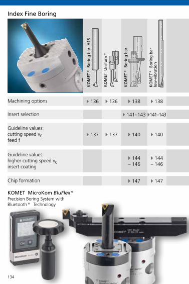
134
KO
MET
Un
iTu
rn®
KO
MET
Mic
roK
om
® h
i.flex
KO
MET
Mic
roK
om
Blu
Flex
®
KO
MET
Mic
roK
om
® M
040
KO
MET
Mic
roK
om
® M
03Sp
eed
KO
MET
Tw
inK
om
®
E 136 E 136 E 138 E 138 E 138 E 138 E 139 E 139 E 139 E 139
E 141–143 E 141–143 E 141–143 E 141–143 E 141–143 E 141–143 E 141–143 E 141–143
E 137 E 137 E 140 E 140 E 140 E 140 E 140 E 140 E 140 E 140
E 144– 146
E 144– 146
E 144– 146
E 144– 146
E 144– 146
E 144– 146
E 144– 146
E 144– 146
E 147 E 147 E 147 E 147 E 147 E 147 E 147 E 147
KOMET MicroKom BluFlex®
Index Fine Boring
Machining options
Insert selection
Guideline values: cutting speed vcfeed f
Guideline values: higher cutting speed vcinsert coating
Chip formation
KO
MET
® B
ori
ng
bar
H15
KO
MET
® B
ori
ng
bar
KO
MET
® B
ori
ng
bar
low
-vib
rati
on
Precision Boring System with Bluetooth® Technology

135
KO
MET
Un
iTu
rn®
KO
MET
Mic
roK
om
® h
i.flex
KO
MET
Mic
roK
om
Blu
Flex
®
KO
MET
Mic
roK
om
® M
040
KO
MET
Mic
roK
om
® M
03Sp
eed
KO
MET
Tw
inK
om
®
E 136 E 136 E 138 E 138 E 138 E 138 E 139 E 139 E 139 E 139
E 141–143 E 141–143 E 141–143 E 141–143 E 141–143 E 141–143 E 141–143 E 141–143
E 137 E 137 E 140 E 140 E 140 E 140 E 140 E 140 E 140 E 140
E 144– 146
E 144– 146
E 144– 146
E 144– 146
E 144– 146
E 144– 146
E 144– 146
E 144– 146
E 147 E 147 E 147 E 147 E 147 E 147 E 147 E 147
Index Fine Boring
KO
MET
® M
icro
-ad
just
able
hea
d
Modern wireless networking is one of the benefits with which the new MicroKom BluFlex® fine adjustment head is equipped. Bluetooth® technology is developed for wirelessly networking devices over short distances. This technology has become standard for small mobile devices.The introduction of Bluetooth® technology in the MicroKom BluFlex® tool system means that the display has been disconnected from the tool head, thereby making it easier and more convenient to read off the data. When adjusting the tool system, the user can move the display to suit the conditions on site, so that it is in his field of view. A specially designed adjustment key with integral Bluetooth® interface is part of the system.With integral part balancing, the MicroKom BluFlex® can reach a rotational speed of up to 20,000 rpm.
Bluetooth® technology is a Bluetooth SIG, Inc. brand name

136
§ § §
§ § §
$ $ $
$ $ $
X X X
X X §
X X §
§ § §
Machining
through hole
blind hole
angled start and drilling out, interrupted cut
cross bore
reverse machining
HRC > 54 through hole
HRC > 54 blind hole
vibration dampening
Machining options
§ very good $ good & possible X not possible
KOMET UniTurn®, Boring Bar H15
Boring bar H15 UniTurn®Boring tool, Copying tool
UniTurn®Boring tool with CBN

137
P
1.0
2.0
2.1
3.0
4.0
4.1
S
5.0
5.1
M
6.0
6.1
7.0
K
8.0
8.1
9.0
9.1
10.0
10.1
10.2
N
12.0
12.1
13.0
13.1
14.0
H
15.0
16.0
40-180 0,015 - 0,025 0,02 - 0,04
40-180 0,015 - 0,025 0,02 - 0,04
60-200 0,015 - 0,025 0,03 - 0,06
40-160 0,015 - 0,025 0,02 - 0,04
40-140 0,015 - 0,025 0,02 - 0,04
20-40 0,010 - 0,020 0,010 - 0,020
15-30 0,010 - 0,020 0,010 - 0,020
40-140 0,015 - 0,025 0,015 - 0,030
40-140 0,010 - 0,020 0,015 - 0,025
40-140 0,010 - 0,020 0,015 - 0,025
40-160 0,010 - 0,030 0,03 - 0,06
40-140 0,010 - 0,030 0,03 - 0,06
40-130 0,010 - 0,025 0,03 - 0,05
40-130 0,015 - 0,030 0,02 - 0,05
40-120 0,015 - 0,030 0,02 - 0,05
40-120 0,015 - 0,030 0,02 - 0,05
40-90 0,015 - 0,030 0,02 - 0,05
60-210 0,015 - 0,030 0,02 - 0,06
60-210 0,010 - 0,025 0,02 - 0,04
70-220 0,010 - 0,025 0,02 - 0,04
70-220 0,015 - 0,030 0,03 - 0,06
70-220 0,015 - 0,030 0,03 - 0,07
60-80 0,01-0,02 ap max 0,07
50-70 0,01-0,02 ap max 0,07
Guideline values for fine boring
Important: For more application details and safety notes see E 86-87!
KOMET UniTurn®, Boring Bar H15
Mat
eria
l gro
upSe
lect
ion:
L.H
. fol
d pa
ge
Cut
ting
spee
d v c
(m/m
in)
Boring bar H15
UniTurn®
Boring tool, Copying tool
UniTurn®
Boring tool with CBN
max. feed f (mm/rev)
max. feed f (mm/rev)
max. feed f (mm/rev)

138
j k
§ § § § § § § §
§ § § § § § § §
$ $ $ $ $ $ $ $
$ $ $ $ $ $ $ $
X X X X § § X X
§ & $ $ $ § § §
§ & $ $ $ § § §
X § X X X § § X
MicroKom BluFlex®
MicroKom® hi.flex
Machining
through hole
blind hole
angled start and drilling out, interrupted cut
cross bore
reverse machining
HRC > 54 through hole
HRC > 54 blind hole
vibration dampening
Machining options
§ very good $ good & possible X not possible
KOMET® Boring Bar
Boring bar Boring bar low-vibration

139
j k
§ § § § § § § §
§ § § § § § § §
$ $ $ $ $ $ $ $
$ $ $ $ $ $ $ $
X X X X § § X X
§ & $ $ $ § § §
§ & $ $ $ § § §
X § X X X § § X
KOMET MicroKom®, TwinKom®
kTwinKom® G01
MicroKom® M040
MicroKom® M03Speed
Machining options
jMicro-adjustable head with insert cartridge

140
W00 W30, W57
P
1.0
2.0
2.1
3.0
4.0
4.1
S
5.0
5.1
M
6.0
6.1
7.0
K
8.0
8.1
9.0
9.1
10.0
10.1
10.2
N
12.0
12.1
13.0
13.1
14.0
H
15.0
16.0
KOMET® W00, W30, W57
W00 04...W30 04...W57 04...
W30 14...W57 14...
W30 26...W57 26...
300 0,04 0,07 0,10 0,15
250 0,04 0,06 0,12 0,20
300 0,04 0,07 0,12 0,25
200 0,03 0,06 0,10 0,20
180 0,03 0,05 0,10 0,15
80 0,02 0,04 0,08 0,12
60 0,01 0,04 0,08 0,10
80 0,01 0,04 0,08 0,10
180 0,01 0,05 0,10 0,15
160 0,01 0,05 0,10 0,15
160 0,01 0,04 0,08 0,15
200 0,05 0,10 0,15 0,30
160 0,05 0,10 0,15 0,30
180 0,04 0,08 0,15 0,25
160 0,04 0,08 0,15 0,25
140 0,04 0,08 0,15 0,25
140 0,03 0,07 0,12 0,25
120 0,03 0,10 0,15 0,25
300 0,02 0,04 0,08 0,20
400 0,05 0,08 0,15 0,20
500 0,02 0,06 0,10 0,15
350 0,05 0,08 0,12 0,20
300 0,05 0,08 0,12 0,20
120 0,05 0,08 0,10
90 0,05 0,08 0,10Important: For more application details and safety notes see E 86-87!
Mat
eria
l gro
upSe
lect
ion:
L.H
. fol
d pa
ge
Cut
ting
spee
d v c
(m/m
in)
max. feed f (mm/rev)
max. feed f (mm/rev)
max. feed f (mm/rev)
max. feed f (mm/rev)
Guideline values for fine boring

141
KOMET® W30, W57
L / D
W30 ..... .31..
2,5 3,5 – 4,5
W30 W30 ..... .30..
R0,0
W30 ..... .32..
R0,2
W30 ..... .39..
R0,05R0,2
W30
R0,4
W57
R0,4
W30
R0,8
W30 ..... .31..
W30
W30 ..... .32..
W57
Subject to length: diameter ratio L/D
• universal insert
surface structure produced
• for good chip control• for R.H. and L.H. cutting direction
surface structure produced
• very good surface quality at high feed rates• subject to stable conditions (max. 2×D)• for interrupted cut
• for large cut outs• for good chip control
surface structure produced surface structure produced
Insert geometry selection

142
KOMET® W30, W57
0,05
0,1
0,2
0,3
0,4
ap
W30 14... .31.. W30 26... .31..
W30 26... .08..
R0,8
W30 14... .08..
R0,8
W30 14... .04..W30 26... .04..
R0,4 UF
W30 ..... .02..R0,2
W30 ..120.30..R0,0
W30 ..120.32..US
W57 ..040. ....R0,4
W57 ..140. ....R0,2R0,4
W30 ..820.32..US
W30 ..... .39..R0,05
Subject to cutting depth ap in the radius – machining steel
Insert geometry selection

143
KOMET® W30, W32, W37, W57, W58
0,15
0,25
0,75
1,5
2,0
ap
W57 14120. ..23W57 26120. ..23
W30 04990. ..55W32 03990.0455
W57 04120.0223
0,5
1,0
W58 13120. ..23W58 18120. ..23W58 23120. ..23
2,5
3,0
3,5
4,0
W32 23150.04..W32 32150.04..
W32 13150.04..W32 18150.04..
W58 03120.0423
W32 03150.04..
W32 ..940. .. W32 ..600. .. W37 ..600. ..
W30 18990.0455W30 23990.0455W30 32990.0455
W30 14990. ..55W30 26990. ..55W32 13990.0455
W32 44150.08..
Subject to cutting depth ap in the radius – machining aluminium
Insert geometry selection

144
P M K NP25M P40 BK
6425BK
6110BK
6440BK
2710BK
8425CK30
CK32
CK37
CK38
CBN40
P25M P40 BK
2710BK
8425CK30
CK32
CK37
CK38 K10 BK
7615BK
6110BK
2710CBN57 K10 PKD
5540 >52HRC 4050 5060 6070 7080 8090 90100 100110 110120 120130 130140 140150 150160 160170 170180 180190 190200 200210 210220 220230 230240 240250 250260 260270 270280 280290 290300 300310 310320 320330 330340 340350 350360 360370 370380 380390 390400 400410 410420 420430 430440 440450 450460 460470 470480 480490 490500 500600 600700 700800 800900 900
1000 10001100 1100
KOMET® W30
vc (m/min)
Guideline values for fine boring
Cutting speed

145
P M K NP25M P40 BK
6425BK
6110BK
6440BK
2710BK
8425CK30
CK32
CK37
CK38
CBN40
P25M P40 BK
2710BK
8425CK30
CK32
CK37
CK38 K10 BK
7615BK
6110BK
2710CBN57 K10 PKD
5540 >52HRC 4050 5060 6070 7080 8090 90100 100110 110120 120130 130140 140150 150160 160170 170180 180190 190200 200210 210220 220230 230240 240250 250260 260270 270280 280290 290300 300310 310320 320330 330340 340350 350360 360370 370380 380390 390400 400410 410420 420430 430440 440450 450460 460470 470480 480490 490500 500600 600700 700800 800900 900
1000 10001100 1100
KOMET® W30
vc (m/min)
Important: For more application details and safety notes see E 86-87!
Guideline values for fine boring

146
P M K NBK
8430BK60
CK3230
CK3210
BK8430
CK3230
CK3210
BK60
K10 BK7710
40506070809010011012013014015016017018019020021022023024025026027028029030031032033034035036037038039040041042043044045046047048049050060070080090010001100
KOMET® W57
vc (m/min)
Guideline values for fine boring
Cutting speed
Important: For more application details and safety notes see E 86-87!

147
KOMET® W30, W57
W30 14... W30 14... (UF)
W30 14...(US)
W57 14140.04..
Material:42CrMo4V1100 N/mm²
Cutting data:vc = 240 m/minf = 0,08 mm/revap = 0,12 mm
Material:St37350 N/mm²
Cutting data:vc = 300 m/minf = 0,08 mm/revap = 0,12 mm
Material:X10CrNiMoTi18750 N/mm²
Cutting data:vc = 160 m/minf = 0,08 mm/revap = 0,12 mm
Chip formation from various insert geometries
Tool: Micro-adjustable head MicroKom® M03Speed

148
E F F
P P P
M M M
K K K
N N N
S S S
H H H
6°
P P P
M M M
K K K
N N N
S S S
H H H
12°
P P P
M M M
K K K
N N N
S S S
H H H
20°
P P P
M M M
K K K
N N N
S S S
H H H
PKD55PKD5520
Recommendations for using inserts with ground chip grooves(W00, W01, W04, W30, W32, W34, W37, W60)
rounded sharp-edged chamfered
KOMET® Guidelines Selecting the top rake

149
KOMET® ISO Code for inserts
723
W N M G 0 8 0 4 0 8 F L – 0 1a b c d e f g h i j
a
R
S 90°
L 90°
A 85°
T 60°
C 80° / 100°
E 75°
D 55°
V 35°
W 80°
b
N 0°
B 5°
C 7°
O
P 11°
E 20°
f
T0 1,20 mm
01 1,59 mm
T1 1,80 mm
02 2,38 mm
T2 2,97 mm
03 3,18 mm
T3 3,97 mm
04 4,76 mm
05 5,30 mm
06 6,35 mm
07 7,94 mm
g
00 0,0 mm
01 0,1 mm
02 0,2 mm
03 0,3 mm
04 0,4 mm
05 0,5 mm
06 0,6 mm
08 0,8 mm
12 1,2 mm
16 1,6 mm
20 2,0 mm
24 2,4 mm
ZZ
h
F
E
T
S
i
R
L
N
j
-01
-05
-11
-13
-14
-15
-21
-32
-33
c
s
m
m
d1
d1 s
m s dA ±0,005 ±0,025 ±0,025E ±0,025 ±0,025 ±0,025G ±0,025 ±0,13 ±0,025H ±0,013 ±0,025 ±0,013K ±0,013 ±0,025 ±0,05...±0,15M ±0,08...±0,181) ±0,13 ±0,05...±0,131)
U ±0,13...±0,381) ±0,13 ±0,08...±0,251)
x d1
6,35 ±0,08 ±0,13 d±0,05 ±0,08
9,52 ±0,08 ±0,13 d±0,05 ±0,08
12,70 ±0,13 ±0,20 ±0,08 ±0,13
15,87 ±0,15 ±0,27 ±0,10 ±0,18
19,05 ±0,15 ±0,27 ±0,10 ±0,18
25,40 ±0,18 ±0,38 ±0,13 ±0,25
d
A
M
G
R
W
B
T
H
P
U
X
e
d1mm A C D L R S T V W3,97 06 024,80 04 035,56 05 05 096,35 10 06 07 06 11 11 047,94 08 07 13 138,00 12 08 08 14 059,52 09 11 12 09 16 16
10,00 10 0610,90 1612,00 12 0812,70 12 15 12 22 2215,00 1015,88 15 2716,00 1617,60 1219,05 19 19 33 1320,00 2025,00 2525,40 25
ISO Codes for Inserts
Form
Code
Thickness s
Code
Corner radius RCode
Cutting edge designCode
sharp
rounded
chamfered (negative)
chamfered + rounded
Cutting direction of insertCode
R.H.
L.H.
R.H. and L.H.
Tolerance
Code
Tolerance in mmat m at m at d1 at d1
IC Class M Class U Class M Class U
Type
Code
no chipformer, with hole
chipformer on one side, with hole
chipformer both sides, with hole
chipformer on one side, no hole
no chipformer, countersunk hole 40-60°
no chipformer, countersunk hole 70-90°
chipformer on one side, countersunk hole 40-60°chipformer on one side, countersunk hole 70-90°
neg/pos. one or two sides, with hole
chipformer both sides, with countersunk hole
special design, drawing required
Cutting edge length lCode
at code
Face cutting edge
Chipfomer
Code
medium
Cast iron
Aluminium
finishing
semi-finishing
Clearance angle
Code
according to manufac-turer specification(with KOMET 8°)

150
KOMET® Numerical Codingfor inserts C.. / W..
1
2
3
4
5
6
7
724
C 8 5 1 8 0 1 0 . 0 4 7 5 2 5W 6 0 3 2 0 6 0 . 0 8 6 0W 2 9 2 4 0 1 0 . 0 4 8 4 2 5
� � � � � � �
�
d1
d1
d1
d1
d1
03 3,97 mm04 4,0 mm10 4,8 / 5,0 mm12 5,5 mm13 5,56 mm14 5,6 mm17 6,0 mm18 6,2 / 6,35 mm20 7,0 / 7,1 mm22 7,7 mm23 7,94 mm24 8,0 mm26 8,2 mm28 8,9 mm32 9,52 / 9,8 mm34 10,0 mm38 10,9 / 11,1 mm42 12,0 mm44 12,7 mm46 13,2 mm50 15,0 mm53 15,88 mm58 17,6 mm
�
84°
00
01
04
05
24
25
27
28
29
60°
30
32
34
36
37
57
58
5955°
60
35°78
55°79
90°80
82
83
�
00
06
12
15
18
20
30
36
42
45
48
50
60
66
70
72
80
82
83
94
98
99
00
01
02
03
04
05
06
07
10
11
12
13
14
15
16
17
18
20
21
32
33
�
�
01 R 0,1 mmR
R
R
R
02 R 0,2 mm03 R 0,3 mm04 R 0,4 mm05 R 0,5 mm06 R 0,6 mm08 R 0,8 mm12 R 1,2 mm30 U8.00 R 031 UF32 US
33 U8.77
34 F / KUF 90°35 F / KUF 75°36 F / KUF 60°39 R 0,05 mm407590
�
1 ... 9
�
03 P25M
04 P40
22 K20
60 BK60
2715 BK2715
2730 BK2730
6115 BK6115
...
Inscribed circle d1
Code
Code ground
L.H. cutting, neutral
L.H. cutting, 6°
L.H. cutting, 12°
L.H. cutting, 15°
L.H. cutting, 18°
L.H. cutting, 20°
R.H. cutting, neutral
R.H. cutting, 6°
R.H. cutting, 12°
R.H. cutting, 15°
R.H. cutting, 18°
R.H. cutting, 20°
neutral
3× ground, 6°
3× ground, 10°
3× ground, 12°
3× ground, 20°
L.H. cutting, 12° sharp-edged
R.H. cutting, 12° sharp-edged
neutral, bright complete, L.H. and R.H. cutting
bright with fl ute on corner, L.H. and R.H. cutting
neutral, bright on corner, L.H. and R.H. cutting
Type of chip groove / chip surfaceMain group for standard insertsCode
Code sintered
Double chip groove (PD), cutting edge rounded
Double chip groove (K), cutting edge chamfered and rounded
Step geometry (KS), cutting edge chamfered and rounded
Dimple geometry (KX), cutting edge rounded
Finished geometry
10° chip groove (T), cutting edge rounded
12° chip groove (C), cutting edge rounded
Finished geometry
Shank geometry, cutting edge chamfered and rounded
20° chip groove, cutting edge rounded
Al / fi nished geometry
Shank geometry, cutting edge rounded
Finishing-Topographie
Semi-fi nishing Topographie
Semi-fi nishing Topographie with "Wiper" corner
22° Topographie / tangential insert
Finishing-Topographie with "Wiper" corner
Universal topography8° top rake
20° Highly positive "Technology 21"
peripheral ground with minimal burring
peripheral sintered with minimal burring
Numerical Coding for Inserts C.. / W..
Modifi cation code
Code
Material grade
Code Code
Secondary group number insert geometry
Code Form Version peripheral Chip groove
Clearance angle,other
Unisix® standard ground ground
Unisix® strengthened ground ground
Unisix® 6 edged ground ground 0°
Unisix® 6 edged ground ground 0°, wide fl ute
Unisix® 95° strengthened sintered sintered
Unisix® standard sintered sintered
Unisix® 95° strengthened ground sintered
Unisix® standard ground sintered
Unisix® strengthened sintered
triangular ground ground 8°
triangular ground ground 11°
triangular strengthened ground ground
triangular 6 edged ground ground 0°
triangular ground ground 20°
triangular ground sintered 11°
triangular ground sintered IC tolerance ±0,025
triangular strengthened ground sintered
rhomboid ground ground
rhomboid ground sintered
rhomboid ground sintered
square sintered sintered
square ground sintered
square sintered sintered
Geometry of cutting edge
Code
15° clearance angle ad-ditional cutt. edge form for Unisix® mill. cutter inserts
45° corner for chamfering cartridge
Support chamfer 75° L.H.Support chamfer 90° L.H.

151
1
2
3
4
5
6
7
725
W 8 5 1 8 0 0 0 . 0 8 8 4 2 5� � � � � � �
�
d1
d1
d1
13 5,56 mm
18 6,35 mm
24 8,0 mm
32 9,52 mm
38 11,1 mm
44 12,7 mm
53 15,88 mm
62 19,05 mm
�
1 ... 9
�
�
83
84
85
86
89
90
95
97
�
00 ... 99
�
01 ... 99
Q 2 1 4 4 0 0 0 . 0 1 2 7 3 0Q 8 0 3 2 0 0 0 . 0 1 6 1 1 5
� � � � � � �
�
d1
d1
d1
13 5,56 mm
18 6,35 mm
24 8,0 mm
32 9,52 mm
38 11,1 mm
44 12,7 mm
53 15,88 mm
�
1 ... 9
�
�
03 P25M
04 P40
22 K20
2715 BK2715
2730 BK2730
6115 BK6115
...
�
09
12
15
21
36
80
�
00 ... 99
�
01 ... 99
�
03 P25M
04 P40
22 K20
2715 BK2715
2730 BK2730
6115 BK6115
...
Inscribed circle d1
Code
Modifi cation code
Code
Main group for standard insertsCode
Numerical Coding for Inserts W..
Secondary group number insert geometry
Code ISO basic forms
S... square 90°
T... triangular 60°
C... rhomboid 80°
D... rhomboid 55°
V... rhomboid 35°
W... hexagonal 80°
R... round
threaded
Serial number
Code
Serial number
Code
Inscribed circle d1
Code
Modifi cation code
Code
Main group for standard insertsCode
Material grade
Code
Numerical Coding for Inserts Q..
Secondary group number insert geometry
Code ISO basic forms
S... square 90°
T... triangular 60°
C... rhomboid 80°
E... rhomboid 75°
A... rhomboid form
L... square 90°
Serial number
Code
Serial number
Code
Programme ISO
Material grade
Code
KOMET® Numerical Codingprogramme ISO
for inserts Q..

152
ap = 0,5 – 4,26 mmf = 0,1 – 0,36 mm
ap = 0,05 – 2,5 mmf = 0,05 – 0,25 mm
ap = 0,5 – 4,26 mmf = 0,11 – 0,26 mm
ap = 0,14 – 1,16 mmf = 0,02 – 0,11 mm
ap = 0,38 – 7,1 mmf = 0,05 – 0,5 mm
ap = 0,25 – 3,23 mmf = 0,03 – 0,28 mm
KOMET® InsertInsert geometries on example of ISO insert C85
Figures given depend on insert size and corner radius (see catalogue "KomPass – Bore machining")
Geometry -01:Rough machining
Geometry -14:Finish machining for Cermet
Geometry -05: Roughing/ semi-finishing for machining cast iron
Geometry -14:Finish machining for coated carbide
Geometry -12:Semi-finishing
Geometry -15:Semi-finishing
Types of wear
Wear on clearance facenormal type of wear expectedremedy:• use hardened/wear-resistant cutting materials• reduce cutting parameters
Microscopic fracturing caused by:• coating/substrate too brittle• vibrations on part or tool• interrupted cut• build-up on cutting edgescorrecting by: • tougher coating • avoidance of vibrationsn • avoidance of build-up on cutting edges

153
Pitting caused by:• coating/substrate not sufficiently wear-resistant• chip geometry too negativerectified by:• substrate or coatings with better wear resistance• positive chip geometries
Stress fracture caused by:• wrong/excessively high cutting parameters• no allowance for tool restrictions • interrupted cutrectified by:• checking of cutting data• checking of tool restrictions
Thermal wear caused by:• cutting speed too high• excessive heatrectified by:• reduction of cutting speed• wear-resistant, more thermally stable coatings or substrate
Fracture of centre insertcaused by:• basic substrate/coatings too brittle• central position of internal insert too high (insert protrudes over centre)rectified by:• tougher coatings and substrate• check lower central position of internal insert• use centre plate with stronger chamfering• use internal and external insert with same geometry
Plastic deformation of KUB Quatron® cutting edge
• cutting material too soft• replace insert with more wear-resistant type
KOMET® InsertTypes of wear

154
JEL®
MG
F X
H M
icro
JEL®
MG
F, U
MG
F, M
KG
JEL®
GW
F
JEL®
PK
D M
GF
JEL®
PK
D G
WF
JEL®
XA
M
JEL®
TO
MIL
L C
UT
JEL®
BG
F, U
BG
F
JEL®
DB
GF
JEL®
DO
REX
, TA
REX
, SI
REX
JEL®
FED
UB
, FE
DU
C
JEL®
MO
REX
E 156 E 156 E 156 E 156 E 156 E 156 E 156 E 157 E 157
E 158E 158– 162
E 158– 159
E 158– 159
E 158– 162
E 158– 162
E 158– 162
E 158 E 158 – 159 E 158 – 159
E 163 E 163
E 164 E 164 E 168 E 169 E 167 E 167E 170 – 171
E 171 E 172 E 173
E 174– 175
E 174– 175
E 174– 175
E 174– 175
E 174– 175
E 176– 177
E 176– 177
E 176– 177
E 176– 177
E 176– 177
E 176– 177
E 176– 177
E 176– 177
E 178– 179
E 178– 179
E 178– 179
E 178– 179
E 178– 179
E 178– 179
E 178– 179
E 178– 179
E 182 E 182 E 182 E 182 E 182E 180– 181
E 180– 181
E 184 – 185 E 183
Index Threading
Producing internal threads
Tap drill diameters for threads
Achievable thread lengths
Guideline values cutting speed vc milling feed fz drilling feed fb
CNC program explanation
Formulae
Setting
Problemscauses solutions
Thread milling tool

155
JEL®
MG
F X
H M
icro
JEL®
MG
F, U
MG
F, M
KG
JEL®
GW
F
JEL®
PK
D M
GF
JEL®
PK
D G
WF
JEL®
XA
M
JEL®
TO
MIL
L C
UT
JEL®
BG
F, U
BG
F
JEL®
DB
GF
JEL®
DO
REX
, TA
REX
, SI
REX
JEL®
FED
UB
, FE
DU
C
JEL®
MO
REX
E 156 E 156 E 156 E 156 E 156 E 156 E 156 E 157 E 157
E 158E 158– 162
E 158– 159
E 158– 159
E 158– 162
E 158– 162
E 158– 162
E 158 E 158 – 159 E 158 – 159
E 163 E 163
E 164 E 164 E 168 E 169 E 167 E 167E 170 – 171
E 171 E 172 E 173
E 174– 175
E 174– 175
E 174– 175
E 174– 175
E 174– 175
E 176– 177
E 176– 177
E 176– 177
E 176– 177
E 176– 177
E 176– 177
E 176– 177
E 176– 177
E 178– 179
E 178– 179
E 178– 179
E 178– 179
E 178– 179
E 178– 179
E 178– 179
E 178– 179
E 182 E 182 E 182 E 182 E 182E 180– 181
E 180– 181
E 184 – 185 E 183
Index ThreadingDrill thread milling toolThread milling tool Tap Roll form tap

156
MethodsJEL® Producing Internal Threads
Thread milling
• Chip producing method• Thread making by helical interpolation within
the pitch• Same tool can be used for all threads with the
same pitch starting from the nominal x • Same tool can be used for different materials
up to 45 HRC• Lower torque than with tapping and roll form
tapping• Drill depth = thread depth if tool is not used
for chamfering • Machine spindle always running in the same
direction – no reversing necessary• High speed cutting (HSC) possible
Drill thread milling
• Chip producing method• Complete thread is manufactured in a single
pass – drilling, chamfering and thread milling • One tool per dimension which can also be used
for different materials• Prerequisite: CNC machine or machining centre
being capable to run helical interpolation
Drill thread milling: machining sequence

157
MethodsJEL® Producing Internal Threads
• Chip producing method• Thread making by rotation – pitch is on the tool• Can be used on almost all machines• 1 tool per dimension required
Tapping
Through holeJEL tap Type: Dorex
Blind holeJEL tap Type: Sirex SR
Blind and through holeShort chipping materialsJEL tap Type: GG
• Chip less method• Thread making by forming – pitch is on the tool• Suitable for materials with elongation of >5% and tensile strength of
<1000N/mm2
• Tap drill Ø larger than with tapping• Higher torque than tapping• Generates forming gap at minor diameter
Thread forming – grain structure
Roll form tapping
forming gap

158
M 1 1,0 0,25 0,75 – – –
M 1,1 1,1 0,25 0,85 – – –
M 1,2 1,2 0,25 0,95 – – –
M 1,4 1,4 0,30 1,10 – – –
M 1,6 1,6 0,35 1,25 – – –
M 1,8 1,8 0,35 1,45 – – –
M 2 2,0 0,40 1,60 2,0 0,40 1,84
M 2,2 2,2 0,45 1,75 2,2 0,45 2,02
M 2,5 2,5 0,45 2,05 2,5 0,45 2,32
M 3 3,0 0,50 2,50 3,0 0,50 2,80
M 3,5 3,5 0,60 2,90 3,5 0,60 3,25
M 4 4,0 0,70 3,30 4,0 0,70 3,71
M 4,5 4,5 0,75 3,70 4,5 0,75 4,19
M 5 5,0 0,80 4,20 5,0 0,80 4,67
M 6 6,0 1,00 5,00 6,0 1,00 5,54
M 7 7,0 1,00 6,00 7,0 1,00 6,54
M 8 8,0 1,25 6,80 8,0 1,25 7,43
M 9 9,0 1,25 7,80 9,0 1,25 8,43
M10 10,0 1,50 8,50 10,0 1,50 9,31
M11 11,0 1,50 9,50 11,0 1,50 10,31
M12 12,0 1,75 10,20 12,0 1,75 11,20
M14 14,0 2,00 12,00 14,0 2,00 13,0
M16 16,0 2,00 14,00 16,0 2,00 15,0
M18 18,0 2,50 15,50 – – –
M20 20,0 2,50 17,50 – – –
JEL® MTap drill diameters for threads
Note for formed threads: The core diameters listed are guidelines. The actual core diameters have to be investigated in use as these depend on the fluidity of the material and the forming speed.
M – Metric thread
Sizemilled and cut threads formed threads
Nom. x Pitch Core x Nom. x Pitch Core x

159
JEL® MF
M4×0,5 4 0,50 3,50 4 0,50 3,80M5×0,5 5 0,50 4,50 5 0,50 4,80M6×0,5 6 0,50 5,50 6 0,50 5,80M6×0,75 6 0,75 5,30 6 0,75 5,69M8×0,5 8 0,50 7,50 8 0,50 7,80M8×0,75 8 0,75 7,30 8 0,75 7,69M8×1 8 1,00 7,00 8 1,00 7,54M10×0,75 10 0,75 9,30 10 0,75 9,69M10×1 10 1,00 9,00 10 1,00 9,54M12×1 12 1,00 11,00 12 1,00 11,54M12×1,5 12 1,50 10,50 12 1,50 11,31M14×1 14 1,00 13,00 14 1,00 13,54M14×1,5 14 1,50 12,50 14 1,50 13,31M15×1,5 15 1,50 13,50 15 1,50 14,31M16×1 16 1,00 15,00 16 1,00 15,54M16×1,5 16 1,50 14,50 16 1,50 15,31M17×1,5 17 1,50 15,50 17 1,50 16,31M18×1 18 1,00 17,00 18 1,00 17,54M18x1,5 18 1,50 16,50 18 1,50 17,31M18×2 18 2,00 16,00 18 2,00 17,00M20×1 20 1,00 19,00 20 1,00 19,54M20×1,5 20 1,50 18,50 20 1,50 19,31M20×2 20 2,00 18,00 20 2,00 19,00M22×1 22 1,00 21,00 22 1,00 21,54M22×1,5 22 1,50 20,50 22 1,50 21,31M22×2 22 2,00 20,00 22 2,00 21,00M24×1 24 1,00 23,00 24 1,00 23,54M24×1,5 24 1,50 22,50 24 1,50 23,31M24×2 24 2,00 22,00 24 2,00 23,00M30×1,5 30 1,50 28,50 30 1,50 29,31
Tap drill diameters for threads
MF – Metric fine thread
Sizemilled and cut threads formed threads
Nom. x Pitch Core x Nom. x Pitch Core x

160
Nr. 10 4,820 24 3,90 4,820 24 4,33
Nr. 12 5,486 24 4,50 5,486 24 5,00
1/4 6,350 20 5,10 6,350 20 5,77
5/16 7,938 18 6,60 7,938 18 7,29
3/8 9,525 16 8,00 9,525 16 8,79
7/16 11,112 14 9,40 11,112 14 10,28
1/2 12,700 13 10,80 12,700 13 11,80
9/16 14,288 12 12,20 14,288 12 13,23
5/8 15,875 11 13,50 – – –
JEL® UNC, UNF
Nr. 10 4,826 32 4,05 4,826 32 4,50
Nr. 12 5,486 28 4,60 5,486 28 5,11
1/4 6,350 28 5,45 6,350 28 5,98
5/16 7,938 24 6,90 7,938 24 7,45
3/8 9,525 24 8,45 9,525 24 9,04
7/16 11,112 20 9,85 11,112 20 10,53
1/2 12,700 20 11,45 12,700 20 12,12
9/16 14,288 18 12,90 14,288 18 13,64
5/8 15,875 18 14,45 15,875 18 15,23
Tap drill diameters for threads
Note for formed threads: The core diameters listed are guidelines. The actual core diameters have to be investigated in use as these depend on the fluidity of the material and the forming speed.
UNC – American unified coarse thread
Sizemilled and cut threads formed threads
Nom. x Pitch t.p.i.
Core x Nom. x Pitch t.p.i.
Core x
UNF – American unified fine thread
Sizemilled and cut threads formed threads
Nom. x Pitch t.p.i.
Core x Nom. x Pitch t.p.i.
Core x

161
x D1
JEL® NPT, NPTF
1/16 27 6,15 6,10
1/8 27 8,50 8,45
1/4 18 11,00 10,90
3/8 18 14,50 14,30
1/2 14 17,85 17,60
3/4 14 23,20 23,00
1“ 11 1/2 29,00 28,75
1 1/4“ 11 1/2 37,80 37,50
1 1/2“ 11 1/2 44,00 43,75
2“ 11 1/2 56,00 55,75
Tap drill diameters for threads
NPT, NPTF – without using a reamer
Sizemilled and cut threads
Pitch t.p.i.
Core x D1NPT
Core x D1NPTF

162
JEL® G
G 1/8“ 9,728 28 8,82
G 1/4“ 13,157 19 11,82
G 3/8“ 16,662 19 15,32
G 1/2“ 20,955 14 19,10
G 5/8“ 22,911 14 21,10
G 3/4“ 26,441 14 24,60
G 7/8“ 30,201 14 28,40
G 1“ 33,249 11 30,80
G 1 1/8“ 37,897 11 35,50
G 1 1/4“ 41,910 11 39,50
G 1 3/8“ 44,323 11 41,90
G 1 1/2“ 47,803 11 45,40
G 1 3/4“ 53,746 11 51,40
G 2“ 59,614 11 57,20
Tap drill diameters for threads
G – pipe thread DIN EN ISO 228
Sizemilled and cut threads
Nom. x Pitch t.p.i.
Core x

163
2 × D 2 × D
2 × D 2 × D
2,5 × D 2 × D 2,5 × D
2 × D 2 × D 2,5 × D
1,5 × D 1,5 × D
1,5 × D 1,5 × D
2,5 × D 2 × D 2,5 × D
2,5 × D 2 × D 2,5 × D
2,5 × D 2 × D 2,5 × D
JEL® (Drill) Thread Milling Tool
Advantage with drill thread milling:• only 1 tool for drilling, countersinking and thread milling
Advantages with thread milling:• one and the same tool for blind bore and through hole• one and the same tool for different diameters > nominal x with the
same pitch• one and the same tool for different tolerances• one and the same tool for different materials
Achievable thread lengths
Material
Drill thread milling BGF
Thread milling MKG
Thread milling MGF
Steel
Stainless steel
Grey cast iron
Nodular grey cast iron
Titanium alloys
Nickel alloys
Copper alloys
Aluminium
Plastics

164
vc (m/min)
TiCN
m x 6 m x 12 M x 16
P
1.11.21.31.41.51.6
H
1.71.8
M
2.12.22.3
K
3.13.23.33.43.53.63.7
S
4.14.24.35.15.25.3
N
6.16.26.36.47.17.27.37.47.58.18.28.3
JEL® MGF, UMGF, MKG, GWF
80-150 0,015-0,04 0,04-0,06 0,08-0,1580-100 0,015-0,04 0,04-0,06 0,08-0,1580-100 0,015-0,04 0,04-0,06 0,08-0,1580-100 0,015-0,04 0,04-0,06 0,08-0,1560-80 0,01-0,03 0,04-0,06 0,04-0,1050-60 0,01-0,025 0,03-0,05 0,04-0,1030-50 0,01-0,015 0,015-0,02 0,03-0,0820-40 0,01-0,015 0,015-0,0260-80 0,015-0,03 0,03-0,05 0,08-0,1560-80 0,015-0,03 0,03-0,05 0,04-0,1060-80 0,01-0,025 0,02-0,04 0,04-0,10
50-80 80-120 0,02-0,04 0,04-0,10 0,08-0,1550-80 80-120 0,02-0,03 0,04-0,08 0,08-0,12
80-100 0,02-0,04 0,04-0,08 0,08-0,1580-120 0,02-0,04 0,04-0,10 0,08-0,1580-100 0,02-0,03 0,04-0,08 0,08-0,1280-100 0,02-0,04 0,04-0,10 0,08-0,1580-100 0,02-0,03 0,04-0,08 0,08-0,1240-100 0,015-0,03 0,03-0,08 0,08-0,1540-100 0,015-0,03 0,03-0,08 0,08-0,1540-80 0,015-0,02 0,03-0,06 0,08-0,1250-60 0,02-0,04 0,04-0,06 0,04-0,1030-40 0,02-0,04 0,04-0,06 0,04-0,1010-30 0,015-0,03 0,03-0,05 0,04-0,08
100-300 100-400 0,04-0,07 0,07-0,12 0,10-0,20100-300 100-400 0,04-0,07 0,07-0,12 0,10-0,20100-300 100-400 0,04-0,07 0,07-0,12 0,10-0,2060-80 60-80 0,02-0,04 0,03-0,06 0,08-0,15
100-400 100-400 0,03-0,07 0,07-0,12 0,10-0,20100-400 100-400 0,03-0,07 0,07-0,12 0,10-0,20100-400 100-400 0,03-0,07 0,07-0,12 0,10-0,20100-300 100-400 0,03-0,07 0,07-0,12 0,10-0,20100-200 100-250 0,03-0,07 0,07-0,12 0,10-0,2080-100 100-120 0,04-0,06 0,06-0,12 0,08-0,2080-100 100-120 0,04-0,06 0,06-0,12 0,08-0,1550-60 60-80 0,04-0,06 0,06-0,12 0,08-0,15
vc = Cutting speed · fb = Drilling feed · fz = Milling feed
Guideline values for thread milling
fz (mm/tooth)Surface uncoatedNom. x

165
JEL® MGF HPC
vc (m/min)
AlCrN
M4 – M6 M8 – M12 M14 – M20
P
1.11.21.31.41.51.6
H
1.71.8
M
2.12.22.3
K
3.13.23.33.43.53.63.7
S
4.14.24.35.15.25.3
N
6.16.26.36.47.17.27.37.47.58.18.28.3
80 - 100 0,015 - 0,020 0,020 - 0,030 0,030 - 0,04080 - 100 0,015 - 0,020 0,020 - 0,030 0,030 - 0,04080 - 100 0,015 - 0,020 0,020 - 0,030 0,030 - 0,04080 - 100 0,015 - 0,020 0,020 - 0,030 0,030 - 0,04080 - 100 0,015 - 0,020 0,020 - 0,030 0,030 - 0,04080 - 100 0,015 - 0,020 0,020 - 0,030 0,030 - 0,040
100 - 120 0,020 - 0,040 0,040 - 0,080 0,060 - 0,100100 - 120 0,020 - 0,030 0,040 - 0,060 0,060 - 0,080100 - 120 0,020 - 0,030 0,040 - 0,060 0,060 - 0,08080 - 100 0,020 - 0,030 0,040 - 0,060 0,060 - 0,08080 - 100 0,020 - 0,030 0,040 - 0,060 0,060 - 0,08080 - 100 0,020 - 0,030 0,040 - 0,060 0,060 - 0,08080 - 100 0,020 - 0,030 0,040 - 0,060 0,060 - 0,08060 - 80 0,015 - 0,020 0,020 - 0,030 0,030 - 0,04060 - 80 0,015 - 0,020 0,020 - 0,030 0,030 - 0,04060 - 80 0,010 - 0,015 0,015 - 0,020 0,025 - 0,035
fz (mm/tooth)Surface
Nom. x
Guideline values for thread milling – specially for JEL® MGF HPC
Important: For more application details and safety notes see E 86-87!

166
JEL® MKG
JEL® TPT
ES ES
How the deburring edge works
Software for thread milling tools
Every thread, whether cut or formed, begins as a burr. The full thread profile is obtained as the pitch progesses when plunged into the solid material.In screwed connections that are fre-quently unscrewed and then recon-nected, this burr can come away and cause damage - to hydraulic compo-nents, for example.In order to prevent this, the burr can – as with a thread mating plug gauge – be removed at the start of the thread as the thread is milled, without requiring any additional time, so that the thread starts with a full profile thread.This is done with what is known as a de-burring edge (ES), which is positioned on the tool behind the thread profile. The amount of material removed depends on the position where the edge is applied.
Risk of burr formation and of the burr beco-ming detached at the transition between the thread and the counter-sink – the risk is particu-larly high for lead-free aluminium alloys
Thread with maximum deburring edge effect at a depth of 1×P
Quick and easy tool selection, and generation of CNC programmes for standard thread milling cutters and thread mills manufactured by the KOMET GROUP: 24 hours a day, across the globe, at http://tpt.kometgroup.com
Free service:- Simply register, and you will instantly be provided with
a password- Program is ready to use- You can enter the machining task- All possible tools will be proposed, with the machining
time given for each- Tool drawings will be displayed- CNC programs for six different control systems in six different languages,
in metric or imperial- Also available as “TPT Mobile” app, with the same features, on App
Store for iPhone and iPad, and on Play Store for Androïd smartphones.
Start position End position

167
vc (m/min) vc (m/min)
TiN
P
1.11.21.31.41.51.6
H
1.71.8
M
2.12.22.3
K
3.13.23.33.43.53.63.7
S
4.14.24.35.15.25.3
N
6.16.26.36.47.17.27.37.47.58.18.28.3
JEL® XAM, TOMILL CUT
80-150 0,08-0,15 80-100 0,08-0,1280-100 0,08-0,15 80-100 0,08-0,1280-100 0,08-0,15 80-100 0,08-0,1280-100 0,08-0,15 80-100 0,08-0,1260-80 0,04-0,10 60-80 0,04-0,0850-60 0,04-0,10 50-60 0,04-0,0830-50 0,03-0,08
60-80 0,08-0,15 60-80 0,04-0,0860-80 0,04-0,10 60-80 0,04-0,0860-80 0,04-0,10 60-80 0,04-0,08
50-80 80-120 0,08-0,15 80-120 0,08-0,1550-80 80-120 0,08-0,12 80-120 0,08-0,15
80-100 0,08-0,15 80-100 0,08-0,1580-120 0,08-0,15 80-120 0,08-0,1580-100 0,08-0,12 80-120 0,08-0,1580-100 0,08-0,15 80-120 0,08-0,1580-100 0,08-0,12 80-120 0,08-0,1540-100 0,08-0,15 40-80 0,04-0,0840-100 0,08-0,15 40-80 0,04-0,0840-80 0,08-0,12 40-80 0,04-0,0850-60 0,04-0,10 20-40 0,04-0,0630-40 0,04-0,10 20-40 0,04-0,0610-30 0,04-0,08 20-40 0,04-0,06
100-300 100-400 0,10-0,20 100-300 0,10-0,15100-300 100-400 0,10-0,20 100-300 0,10-0,15100-300 100-400 0,10-0,20 100-300 0,10-0,1560-80 60-80 0,08-0,15
100-400 100-400 0,10-0,20 100-400 0,10-0,15100-400 100-400 0,10-0,20 100-400 0,10-0,15100-400 100-400 0,10-0,20 100-400 0,10-0,15100-300 100-400 0,10-0,20 100-400 0,15-0,20100-200 100-250 0,10-0,20 100-400 0,15-0,2080-100 100-120 0,08-0,20 100-120 0,10-0,2080-100 100-120 0,08-0,15 100-120 0,10-0,1550-60 60-80 0,08-0,15 60-80 0,10-0,15
Guideline values for thread milling
fz (mm/tooth) fz (mm/tooth)Surface uncoatedNom. x
Important: For more application details and safety notes see E 86-87!

168
x 8 x 10 - 12
vc (m/min)
P
1.11.21.31.41.51.6
H
1.71.8
M
2.12.22.3
K
3.13.23.33.43.53.63.7
S
4.14.24.35.15.25.3
N
6.16.26.36.47.17.27.37.47.58.18.28.3
JEL® PKD MGF
300-1000 0,04-0,08 0,05-0,10
400-1500 0,04-0,08 0,04-0,10400-1500 0,04-0,08 0,04-0,10400-1500 0,04-0,08 0,04-0,10400-1500 0,04-0,08 0,04-0,10400-1500 0,04-0,08 0,04-0,10
400-1500 0,04-0,10 0,05-0,20vc = Cutting speed · fb = Drilling feed · fz = Milling feed
Guideline values for PCD drill slot milling tool
Surface uncoatedNom. x
fz (mm/tooth) fz (mm/tooth)
PCD cutting materials are suitable for maximum cutting speeds because of their hardness.PCD tools require careful handling.To prevent fracturing, please use non-contact measuring only. For extended or preset tools the cutting edges should be protected with a cover.

169
JEL® PKD GWF
x 16 x 20
vc (m/min)
P
1.11.21.31.41.51.6
H
1.71.8
M
2.12.22.3
K
3.13.23.33.43.53.63.7
S
4.14.24.35.15.25.3
N
6.16.26.36.47.17.27.37.47.58.18.28.3
300-1500 0,04-0,15 0,05-0,20
400-2000 0,05-0,15 0,06-0,20400-2000 0,05-0,15 0,06-0,20400-2000 0,05-0,15 0,06-0,20400-2000 0,05-0,15 0,06-0,20400-2000 0,05-0,15 0,06-0,20
500-2000 0,05-0,20 0,06-0,25
Guideline values for PCD drill slot milling tool
Important: For more application details and safety notes see E 86-87!
Surface uncoatedNom. x
fz (mm/tooth) fz (mm/tooth)
PCD cutting materials are suitable for maximum cutting speeds because of their hardness.PCD tools require careful handling.To prevent fracturing, please use non-contact measuring only. For extended or preset tools the cutting edges should be protected with a cover.

170
vc (m/min)
TiAlN
m x 6 m x 12 m x 6 m x 12
P
1.11.21.31.41.51.6
H
1.71.8
M
2.12.22.3
K
3.13.23.33.43.53.63.7
S
4.14.24.35.15.25.3
N
6.16.26.36.47.17.27.37.47.58.18.28.3
JEL® BGF, UBGF
50-80 80-120 0,10-0,15 0,15-0,22 0,02-0,05 0,05-0,1050-80 80-120 0,10-0,15 0,15-0,22 0,02-0,05 0,05-0,10
80-100 0,10-0,15 0,15-0,22 0,02-0,05 0,05-0,1050-80 80-120 0,10-0,15 0,15-0,22 0,02-0,05 0,05-0,10
100-300 0,10-0,30 0,06-0,10 0,03-0,06 0,06-0,10
100-400 100-400 0,10-0,25 0,25-0,30 0,03-0,06 0,06-0,10100-400 100-400 0,10-0,25 0,25-0,30 0,03-0,06 0,06-0,10100-400 100-400 0,03-0,06 0,06-0,12 0,03-0,06 0,06-0,10100-300 100-400 0,10-0,25 0,25-0,30 0,03-0,06 0,06-0,10
100-300 0,10-0,25 0,25-0,30 0,03-0,06 0,06-0,1060-120 60-120 0,10-0,25 0,25-0,30 0,03-0,06 0,06-0,1060-100 60-100 0,10-0,25 0,25-0,30 0,03-0,06 0,06-0,1040-60 60-80 0,10-0,15 0,15-0,22 0,02-0,05 0,05-0,10
vc = Cutting speed · fb = Drilling feed · fz = Milling feed
Guideline values for drill thread milling
fb (mm/rev) fz (mm/tooth)Surface uncoatedNom. x

171
JEL® BGF, DBGF
vc (m/min) vc (m/min)
AlCrN TiAlN
P
1.11.21.31.41.51.6
H
1.71.8
M
2.12.22.3
K
3.13.23.33.43.53.63.7
S
4.14.24.35.15.25.3
N
6.16.26.36.47.17.27.37.47.58.18.28.3
100-150 0,03-0,10100-150 0,03-0,10100-150 0,03-0,10100-150 0,03-0,10100-150 0,03-0,10100-150 0,03-0,10
80-120 0,15-0,22 0,05-0,10 100-200 0,05-0,1580-120 0,15-0,22 0,05-0,10 100-200 0,05-0,15
100-150 0,05-0,15100-200 0,05-0,15100-200 0,05-0,15100-200 0,05-0,15100-200 0,05-0,15
100-200 0,05-0,15100-200 0,05-0,15
100-400 0,05-0,20100-400 0,05-0,20100-400 0,05-0,20100-400 0,05-0,20100-300 0,05-0,20100-200 0,05-0,20100-200 0,05-0,20100-150 0,05-0,20
Important: For more application details and safety notes see E 86-87!
Guideline values for drill thread milling
fb (mm/rev) fz (mm/tooth) fz (mm/tooth)Surface
Nom. x

172
vc (m/min) vc (m/min)
HSS
P
1.11.21.31.41.51.6
H
1.71.8
M
2.12.22.3
K
3.13.23.33.43.53.63.7
S
4.14.24.35.15.25.3
N
6.16.26.36.47.17.27.37.47.58.18.28.3
JEL® DOREX, SIREX, TAREX, FEDUB, FEDUC
15-30 20-50 E / O15-25 20-40 E / O15-20 20-35 E / O10-15 20-30 E / O5-10 15-20 O / E2-5 10-15 O
2-8 O2-5 O
5-10 10-25 O4-8 10-20 O3-5 7-12 O
10-20 20-25 20-50 E / T5-10 15-20 20-50 E
10-20 20-40 20-50 E5-10 10-15 20-50 E / O10-15 30-40 20-50 E / O5-10 10-20 20-50 E / O5-15 10-15 E / O3-10 10-15 E / O1-5 5-10 O7-10 10-15 O4-8 5-10 O3-5 4-7 O
10-15 15-20 E / O25-30 40-50 25-60 E / T10-20 30-40 E / O2-5 5-8 5-9 E / O
10-15 20-50 E15-20 20-40 E10-15 20-40 E20-30 25-50 25-80 E15-25 20-30 20-60 E15-25 20-30 E / T5-10 10-15 10-30 E / L3-5 8-12 8-25 E
vc = Cutting speed · *HSS-E with carbide strips
Guideline values for tapping
CoolantE=EmulsionO=OilT=DryL=Air
Cutting material solid carbideSurface uncoated coated uncoated coated

173
vc (m/min) vc (m/min)
HSS
P
1.11.21.31.41.51.6
H
1.71.8
M
2.12.22.3
K
3.13.23.33.43.53.63.7
S
4.14.24.35.15.25.3
N
6.16.26.36.47.17.27.37.47.58.18.28.3
JEL® MOREX
30-50 30-80 E / O30-50 30-80 E / O30-50 30-80 E / O20-30 20-50 O10-20 15-30 O5-10 5-10 O
20-40 20-50 O20-30 20-40 O20-30 20-40 O
20-40 20-60 E / O20-30 20-40 E / O
20-30 O20-2510-1515-20 10-30 O10-15 10-20 O5-10 O
20-50 20-60 20-80 O / E
20-50 20-60 20-80 O / E
20-50 20-60 20-80 O / E20-50 20-60 20-80 O / E20-50 20-60 20-80 O / E20-50 20-60 20-80 O / E20-50 20-60 20-80 O / E
Guideline values for thread forming
CoolantE=EmulsionO=OilT=DryL=Air
Cutting material solid carbide / HML*Surface coated uncoated coated
Important: For more application details and safety notes see E 86-87!

174
Machining task:Thread: M10, depth = 20.560 mm (EL) Bore: blind bore, D = 8.500 mm, cyl. depth = 22.060 mmChamfer steps:1) tapered, D=10.300 mm, W=90.0°
Material:7.2 aluminium alloy (A5 < 14%),AlMn 1 Mg 0,5, 3.0525
Tool:BGF-M10 2.0D, uncoatedMilling tool radius = 3.980 mmEccentricity = 1.020 mmOrder No.: 80.9410.01.000022Drawing No.: 80.9410.01.000022.01Main time: 4.0 sec
Cutting values (external track):vc = 400 m/min n = 14980 rev/minfs = 0.300 mm/rev F = 4494 mm/min (chamfering)fb = 0.300 mm/rev F = 4494 mm/min (drilling)fz1 = 0.100 mm/tooth F1 = 2996 mm/min (thread milling)
NC machine:Drive: standard NC machineMax. spindle speed: 15000 rev/minControl: SinumerikRef.: contour path, incremental
NC options:Entry loop: 180°Exit loop: 180°Milling method: conventional millingChip removal: single, degressive
Note:Deepest tool position = -23.370 mmFor control systems where the feed relates to the central track, the figures given in brackets must be used.
JEL® (Drill) Thread MillingCNC program – step-by-step explanation

175
Note: For formulae and abbreviations used, see the following pages.
The application details given depend on the environmental and application conditions (e.g. machine, ambient temperature, lubricant/coolant used and machining result required): they are based on the correct application condi-tions, correct use and compliance with the spindle speed limits given for the tools.
N5 G00 G53 G40 G60 G90 D0 Z+0.0000 Initialisation, absolute coordinates
N10 G80 Deselect any existing cycles
N15 T1 M06 Tool selection
N20 G54 X+0.0000 Y+0.0000 M07 Zero point shift
N25 Z+1.0000 D1 S14980 M03Move to start pos. 1mm above workpiece
N30 G01 Z-1.3000 F1498Start bore with reduced boring feed
N35 G01 Z-15.6580 F4494 Bore to first boring depth
N40 G00 Z+0.0000Clear chips (“chip clearance”, “blow through”)
N45 G00 Z-14.6580Move to start position for second boring depth
N50 G01 Z-23.3700 Bore to end bore depth
N55 G00 Z+0.0000 Clear chips
;(C O N V E N T I O N A L M I L L I N G)
N60 G00 Z-20.4000Move to start position for thread milling
N65 G01 G91 G42 G64 X+0.0000 Y+3.9800F2996 ;(F340)
Incremental coordinates, select milling radius adjustment, No movement
N70 G02 X+0.0000 Y-8.9800 I+0.0000J-4.4900 Z-0.2250
Entry loop with pitch adjustment (Z = 0.15×P)
N75 G02 X+0.0000 Y+0.0000 I+0.0000J+5.0000 Z-1.5000 ;(F611)
Thread finish milling to nominal dimension (Z=P)
N80 G02 X+0.0000 Y+8.9800 I+0.0000J+4.4900 Z-0.2250 F7490 ;(F851)
Exit loop with pitch adjustment (Z = 0.15×P)
N85 G00 G40 G60 X+0.0000 Y-3.9800 Deselect milling radius adjustment
N90 G00 G53 G40 G90 D0 Z+0.0000 M95 Exit status
N95 M30 End of program
JEL® (Drill) Thread MillingCNC program
NEW: App for iPhone and Androïd

176
n
z
vcfzf
rfe
g
g
D
R1R2z
R3R4
F1 = n × z × fz
e
rf + R1F1 = n × z × fz ×
F2 = n × z × fz
2 × e
DF2 = n × z × fz ×
F3 = n × z × fz × 2,5
F3 = F2 × 2,5
Formula symbols and abbreviations used
r.p.m.
m/min
mm/teeth
mm/rev
mm
mm
mm
mm
mm
mm
mm
mm
mm
mm
Spindle speed
No. of teeth
Cutting speed
Milling feed
Boring feed
Tool radius
Eccentricity
Amount of withdrawal for conventional milling
Amount of withdrawal for climb milling
Nominal thread diameter
Nominal thread radius
Radius entry loop, external path (J)
z dimension entry and exit loop
Radius entry loop, centre path (J)
Radius full circle, centre path (=e)
Path feeds
Formulae
Entry loop contour path
Entry loop centre point path
Full circle contour path
Full circle centre point path
Exit loop contour path
Exit loop centre point path
JEL® (Drill) Thread Milling

177
vc × 1000
D × pn =
D × p × n
1000vc =
rf = R1 – e
e = R1 – rf
g = 1,3 × +
g =
e
tan ( )a2
D
2R1 =
rf + R12
R2 =
z = p × 0,15
e
2R3 =
R4 = e
e
tan ( )a2
pitch
Formulae
where a = 90° countersink angle = tan45° = 1 where countersink angle is 60° the amount of withdrawal is larger
Cutting speed in m/min
Spindle speed in r.p.m.
Tool radius in mm
Eccentricity in mm
Amount of withdrawal for conventional milling in mm
Amount of withdrawal for climb milling in mm
Nominal thread radius in mm
Radius entry loop, external path (J) in mm
z dimension entry and exit loop in mm
Radius entry loop, centre path (J) in mm
Radius full circle, centre path (=e) in mm
JEL® (Drill) Thread MillingFormulae

178
���
�������������������������
���
���
��
��
��
��
��
Tool clamping• Correct alignment of clamping screw on clamping surface for Whistle-
Notch adaptor• Minimise overhang but the cutting sweep for the tool should be beyond
the adaptor
Material: heat treated steelRm = 1000 N/mm2
Cutting values: size: M10vc = 100 m/min fz = 0,06 mm/tooth
Tool measurement• Only measure tool length on pre-setter.• Check concentricity at drill tip resp. thread milling section <0.02 mm• Use tool radius shown on the CNC program
Preparations on machine• Inkey tool length and tool radius into offset register of the control
Program test• Do a test run over the workpiece (increase tool length in tool record)• Check machining time. If the time recorded is clearly different to that
given in the program, there is an error in the feed rate calculation (contour path/centrer point path
• Optimise coolant supply. If flood coolant used, i.e. direct coolant flow onto the milling section of the tool. For through holes use flood coolant if there is no lateral flute coolant supply on the tool.
thermal expansion or hydr. expansion chuckHE cyl. with side screw
collet
run-out error (µm)
Effect of concentricity on tool life using a solid carbide thread milling tool as an example
Setting: Preparations on toolJEL® (Drill) Thread Milling
Lf (%)

179
Cast aluminium• Can be carried out without peck cycle• For tools with internal coolant there is no need for chip clearance after
boring.
Long chipping aluminium • At least once peck cycle• Radial division of cut may be necessary if a thread with very low burring
is required
Grey cast iron• No chip clearance• Conventional thread milling in one path. Over 2×D two pathes may be
required.
Special casesThrough hole• For tool with internal coolant, switch
to external coolant for milling• To reduce side load, preferably work
with milling section on shank side
Angled bore exit / cutting through cross holes• Reduce bore feed rate at bore exit by 60%
Cavities (inclusions) in cast materials • Reduce bore feed rate by 40-60%
JEL® (Drill) Thread MillingSetting: Milling method for different materials

180
Chips packed or glued at the thread profile• poor coolant improve coolant (i.e. add flood coolant, lateral flute
coolant supply for through holes) add coolant flutes flutes on shank
Thread go-gage doesn’t fit• thread too small reduce tool radius in offset register• chips in thread improve coolant
Thread is getting tapered• poor tool clamping improve tool holding (i.e. shrink fit holders)• thread milling feed too high reduce thread milling feed
Erratic tool wear• tool run out too high use better tool holders (i.e. shrink fit holders)
Counterbore chips are winding around the tool• chamfer feed too low increase chamfer feed
Problems possible causes solutionsJEL® Drill Thread Milling Tool

181
Loud drilling noise(especially towards the final drilling depth)• chip problem reduce drill feed rate use tool with coolant through add peck cycle
Tool breakage while drilling(especially in long chipping material)• chip problem reduce drill feed rate use tool with coolant through add peck cycle (multiple pecks)
Chips glued up in the flutes• poor coolant improve coolant situation use tool with coolant through use coated tool
Chippage,tool breakage while thread milling• feed rate thread milling too high check that the chip grooves are free of chips after the
boring operation• vibrations reduce feed rate (check whether NC feeds relate to
centre point or external track)
Poor thread surface (harmonics)• vibrations check tool holder (do not use modular systems !) check workpiece clamping and fixture. Where the
clamping set-up is unstable introduce a distribution of the cutting force.
reduce cutting speed increase tooth feed rate introduce distribution of cutting force
JEL® Drill Thread Milling ToolProblems possible causes solutions

182
Chips packed or glued at the thread profile• poor coolant improve coolant (i.e. add flood coolant, lateral flute
coolant supply for through holes) add coolant flutes flutes on shank
Thread go-gage doesn’t fit• thread too small reduce tool radius in offset register• chips in thread improve coolant
Thread is getting tapered• poor tool clamping improve tool holding (i.e. shrink fit holders)• thread milling feed too high reduce thread milling feed
Erratic tool wear• tool run out too high use better tool holders (i.e. shrink fit holders), check
material for homogeneity
Chippage, tool breakage• feed rate thread milling too high reduce thread milling feed• vibrations check tool holder (don’t use modular systems!!),
change feeds and speeds
Poor thread surface• tool overhang too long check part clamping an and fixture. Use multiple
cuts when part is clamped weak.• non-suitable tool for this application reduce cutting speed, increase feed/tooth, prefer
conventional milling
Problems possible causes solutionsJEL® Thread Milling Tool

183
Forming gap
Thread too tight• tolerance of thread forming tool does not align with
thread gauge use thread forming tool with right tolerance
Core diameter too large on thread• wrong drill diameter (too large) use smaller drill
Core diameter too small or torque too high• drill diameter too small use larger core boring tool
JEL® Roll Form TapProblems possible causes solutions

184
Oversized thread
• wrong tools select the right tools as shown in the catalogue
• cutting edge geometry not suitable for materials to be machined
select the right tools as shown in the catalogue
• material built-up at tap flanks improve coolant system use coated tap
• minor diameter too small, tool is cutting full profile select correct core diameter
• chip jam blind bore: increase spindle speed. Correct tool
selection (spiral flute) through hole: correct tool selection (spiral point)
• tolerance of tap drill to thread gauge does not agree use tap drill with right tolerance
• angular or positional error in core bore adjust workpiece clamping, use tapping chuck with
axis parallel float
Thread too tigh• tolerance of tap drill to thread gauge does not agree use tap drill with right tolerance• wrong tool type select the right tools as shown in the catalogue
Thread is cut wrongly axially• cutting lead pressure on tapping chuck too great select the right cutting lead pressure
Problems possible causes solutionsJEL® Tap

185
NOMINAL ACTUAL
No. of threads
Pitch distortion(plug gauge cannot be screwed in over full thread length on the workpiece)• tap is not cutting true to pitch select right tool select right cutting lead pressure with length adjustment chucks reduce feed to 95%
Thread oversize at the entry• wrong cutting lead pressure use compensation chuck(tension) use lead srcrew select right tool
Thread surface not clean• wrong tool type select right tool• chip jam see “thread too large – chip jam“ • core diameter too small select right core diameter• material built-up on thread flanks use tools with surface treatment improve coolant system• cutting speed to low increase cutting speed
Tool life too short• wrong tool type select right tool type• cutting speed too high or too low adjust cutting speed• composition and supply of coolant inadequate provide suitable, sufficient coolant• premature wear due to lack of or unsuitable surface
treatment use coated tools, if necessary solid carbide tools
JEL® TapProblems possible causes solutions
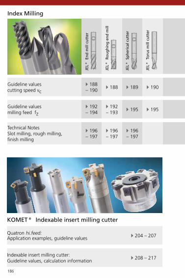
186
E 188 – 190
E 188 E 189 E 190 E 190 E 191 E 191 E 191 E 191 E 198 E 199
E 192 – 194
E 192 – 193
E 195 E 195 E 193 E 193 E 193 E 198 E 199
E 196– 197
E 196– 197
E 196– 197
E 204 – 207
E 208 – 217
Index Milling
Guideline values cutting speed vc
Guideline values milling feed fz
Technical NotesSlot milling, rough milling, finish milling
JEL®
En
d m
ill c
utt
er
JEL®
Ro
ug
hin
g e
nd
mill
JEL®
Sp
her
ical
cu
tter
JEL®
To
rus
mill
cu
tter
JEL®
Ch
amfe
r m
ill c
utt
er
JEL®
Rad
ius
mill
cu
tter
JEL®
En
d m
ill c
utt
er A
L
JEL®
En
d m
ill c
utt
er H
F
JEL®
En
d m
ill c
utt
er A
L
JEL®
PC
D S
lot
mill
ing
cu
tter
JEL®
PC
D F
ace
mill
ing
cu
tter
Quatron hi.feed: Application examples, guideline values
Indexable insert milling cutter: Guideline values, calculation information
KOMET® Indexable insert milling cutter

187
E 188 – 190
E 188 E 189 E 190 E 190 E 191 E 191 E 191 E 191 E 198 E 199
E 192 – 194
E 192 – 193
E 195 E 195 E 193 E 193 E 193 E 198 E 199
E 196– 197
E 196– 197
E 196– 197
E 202 – 203
E 200 – 201
Index Milling
JEL®
En
d m
ill c
utt
er
JEL®
Ro
ug
hin
g e
nd
mill
JEL®
Sp
her
ical
cu
tter
JEL®
To
rus
mill
cu
tter
JEL®
Ch
amfe
r m
ill c
utt
er
JEL®
Rad
ius
mill
cu
tter
JEL®
En
d m
ill c
utt
er A
L
JEL®
En
d m
ill c
utt
er H
F
JEL®
En
d m
ill c
utt
er A
L
JEL®
PC
D S
lot
mill
ing
cu
tter
JEL®
PC
D F
ace
mill
ing
cu
tter
JEL® Milling cutter for machining of composite materials
NCD Composite milling cutter, HSCNCD Composite multi-totth milling cutter
PCD Slot milling cutterPCD Compression milling cutter

188
DIN 6535 HB DIN 6535 HB DIN 6535 HA DIN 6535 HB DIN 6535 HB DIN 6535 HA DIN 6535 HA DIN 6535 HA / HBR
TiAlN TiAlN AlTiN TiAlN TiAlN AlTiN AlTiN TiAlNx 6 - 20 x 6 - 20 x 4 - 16 x 6 - 20 x 3 - 20 x 3 - 16 x 6 - 16 x 3 - 20
vc (m/min) Kf vc (m/min) Kf vc (m/min) Kf vc (m/min) Kf vc (m/min) Kf vc (m/min) Kf vc (m/min) Kf vc (m/min) Kf
P
1.11.21.31.41.51.6
H
1.71.8
M
2.12.22.3
K
3.13.23.33.43.53.63.7
S
4.14.24.35.15.25.3
N
6.16.26.36.47.17.27.37.47.58.18.28.3
165 2 180 2 165 2 170 p4 235 p4 225 p4 165 2135 2 160 2 150 2 160 p4 220 p4 210 p4 135 2125 2 140 2 140 2 150 p4 205 p4 200 p4 125 2125 2 140 2 140 2 150 p4 205 p4 200 p4 125 2100 1 120 1 120 1 130 p4 180 p4 175 p4 100 190 1 100 1 100 1 95 p3 135 p3 125 p3 90 1
80 4 145 p1 140 p160 4 125 p1 120 p1
75 1 110 1 95 p3 75 165 1 110 1 85 p2 65 170 1 110 1 75 p3 70 1150 2 150 2 160 2 225 p4 305 p4 300 p4 150 2130 2 130 2 140 2 210 p4 280 p4 275 p4 130 2130 2 130 2 140 2 210 p4 280 p4 275 p4 130 2130 2 130 2 140 2 190 p4 260 p4 250 p4 130 2110 2 110 2 120 2 160 p4 220 p4 210 p4 110 2110 2 110 2 120 2 145 p4 200 p4 190 p4 110 2110 2 110 2 120 2 145 p4 200 p4 190 p4 110 260 1 60 1 65 1 60 160 1 60 1 65 1 60 155 1 55 1 60 1 55 145 1 45 1 55 p2 45 135 1 35 1 55 p2 35 130 1 30 1 45 p2 30 1175 3 190 3 145 p5 175 3160 3 180 3 140 p5 160 3175 3 190 3 145 p5 175 3100 3 110 3 80 p5 100 3280 3 310 3 520 p5 280 3260 3 285 3 460 p5 260 3260 3 285 3 460 p5 260 3240 3 270 3 270 p5 240 3200 3 220 3 220 p5 200 3160 3 175 3 210 p5 160 3175 3 190 3 225 p5 175 3145 3 160 3 190 p5 145 3
Guideline values for milling
End mill cutter UNI End mill cutter HPC End mill cutter XH Roughing end mill Spherical cutter Spherical cutter XH Spherical cutter XH End mill cutter
Coating
x
JEL® Solid Carbide Milling Cutter
vc = Cutting speed · Kf = Correction factor for feed fz (page 192-195)

189
DIN 6535 HB DIN 6535 HB DIN 6535 HA DIN 6535 HB DIN 6535 HB DIN 6535 HA DIN 6535 HA DIN 6535 HA / HBR
TiAlN TiAlN AlTiN TiAlN TiAlN AlTiN AlTiN TiAlNx 6 - 20 x 6 - 20 x 4 - 16 x 6 - 20 x 3 - 20 x 3 - 16 x 6 - 16 x 3 - 20
vc (m/min) Kf vc (m/min) Kf vc (m/min) Kf vc (m/min) Kf vc (m/min) Kf vc (m/min) Kf vc (m/min) Kf vc (m/min) Kf
P
1.11.21.31.41.51.6
H
1.71.8
M
2.12.22.3
K
3.13.23.33.43.53.63.7
S
4.14.24.35.15.25.3
N
6.16.26.36.47.17.27.37.47.58.18.28.3
165 2 180 2 165 2 170 p4 235 p4 225 p4 165 2135 2 160 2 150 2 160 p4 220 p4 210 p4 135 2125 2 140 2 140 2 150 p4 205 p4 200 p4 125 2125 2 140 2 140 2 150 p4 205 p4 200 p4 125 2100 1 120 1 120 1 130 p4 180 p4 175 p4 100 190 1 100 1 100 1 95 p3 135 p3 125 p3 90 1
80 4 145 p1 140 p160 4 125 p1 120 p1
75 1 110 1 95 p3 75 165 1 110 1 85 p2 65 170 1 110 1 75 p3 70 1150 2 150 2 160 2 225 p4 305 p4 300 p4 150 2130 2 130 2 140 2 210 p4 280 p4 275 p4 130 2130 2 130 2 140 2 210 p4 280 p4 275 p4 130 2130 2 130 2 140 2 190 p4 260 p4 250 p4 130 2110 2 110 2 120 2 160 p4 220 p4 210 p4 110 2110 2 110 2 120 2 145 p4 200 p4 190 p4 110 2110 2 110 2 120 2 145 p4 200 p4 190 p4 110 260 1 60 1 65 1 60 160 1 60 1 65 1 60 155 1 55 1 60 1 55 145 1 45 1 55 p2 45 135 1 35 1 55 p2 35 130 1 30 1 45 p2 30 1175 3 190 3 145 p5 175 3160 3 180 3 140 p5 160 3175 3 190 3 145 p5 175 3100 3 110 3 80 p5 100 3280 3 310 3 520 p5 280 3260 3 285 3 460 p5 260 3260 3 285 3 460 p5 260 3240 3 270 3 270 p5 240 3200 3 220 3 220 p5 200 3160 3 175 3 210 p5 160 3175 3 190 3 225 p5 175 3145 3 160 3 190 p5 145 3
End mill cutter UNI End mill cutter HPC End mill cutter XH Roughing end mill Spherical cutter Spherical cutter XH Spherical cutter XH End mill cutter
Coating
x
Guideline values for millingJEL® Solid Carbide Milling Cutter
Important: For more application details and safety notes see E 86-87!

190
DIN 6535 HAR
DIN 6535 HAR
DIN 6535 HA DIN 6535 HB DIN 6535 HB DIN 6535 HB DIN 6535 HA DIN 6535 HA
AlTiN AlTiN AlTiN TiAlN TiAlN AlTiN TiB2 TiAlNx 4 - 10 x 6 - 10 x 6 - 12 x 6 - 12 x 6 - 8 x 3 - 20 x 6 - 25 x 4 - 8
vc (m/min) Kf vc (m/min) Kf vc (m/min) Kf vc (m/min) vc (m/min) vc (m/min) Kf vc (m/min) Kf vc (m/min) Kf
P
1.11.21.31.41.51.6
H
1.71.8
M
2.12.22.3
K
3.13.23.33.43.53.63.7
S
4.14.24.35.15.25.3
N
6.16.26.36.47.17.27.37.47.58.18.28.3
225 p4 165 165210 p4 135 135200 p4 125 125200 p4 125 125175 p4 100 100125 p4 90 90
80 p4 80 p4 140 p160 p4 60 p4 120 p1
75 7565 6570 70
300 p4 150 150275 p4 130 130275 p4 130 130250 p4 130 130210 p4 110 110190 p4 110 110190 p4 110 110
60 6060 6055 5545 4535 3530 30
175 175 150 3 150 3160 160 140 3 140 3175 175 150 3 150 3100 100 80 3 80 3280 280 500 3 300 - 600 3 500 3260 260 420 3 300 - 600 3 420 3260 260 420 3 300 - 600 3 420 3240 240 270 3 200 - 500 3 270 3200 200 220 3 100 - 300 3 220 3160 160 150 3 150 3175 175 160 3 160 3145 145 120 3 120 3
Guideline values for milling
End mill cutter XH End mill cutter XH Torus mill cutter Chamfer mill cutter Radius mill cutter End mill cutter AL End mill cutter HF End mill cutter AL
Coating
x
JEL® Solid Carbide Milling Cutter
vc = Cutting speed · Kf = Correction factor for feed fz (page 192-195)

191
DIN 6535 HAR
DIN 6535 HAR
DIN 6535 HA DIN 6535 HB DIN 6535 HB DIN 6535 HB DIN 6535 HA DIN 6535 HA
AlTiN AlTiN AlTiN TiAlN TiAlN AlTiN TiB2 TiAlNx 4 - 10 x 6 - 10 x 6 - 12 x 6 - 12 x 6 - 8 x 3 - 20 x 6 - 25 x 4 - 8
vc (m/min) Kf vc (m/min) Kf vc (m/min) Kf vc (m/min) vc (m/min) vc (m/min) Kf vc (m/min) Kf vc (m/min) Kf
P
1.11.21.31.41.51.6
H
1.71.8
M
2.12.22.3
K
3.13.23.33.43.53.63.7
S
4.14.24.35.15.25.3
N
6.16.26.36.47.17.27.37.47.58.18.28.3
225 p4 165 165210 p4 135 135200 p4 125 125200 p4 125 125175 p4 100 100125 p4 90 90
80 p4 80 p4 140 p160 p4 60 p4 120 p1
75 7565 6570 70
300 p4 150 150275 p4 130 130275 p4 130 130250 p4 130 130210 p4 110 110190 p4 110 110190 p4 110 110
60 6060 6055 5545 4535 3530 30175 175 150 3 150 3160 160 140 3 140 3175 175 150 3 150 3100 100 80 3 80 3280 280 500 3 300 - 600 3 500 3260 260 420 3 300 - 600 3 420 3260 260 420 3 300 - 600 3 420 3240 240 270 3 200 - 500 3 270 3200 200 220 3 100 - 300 3 220 3160 160 150 3 150 3175 175 160 3 160 3145 145 120 3 120 3
End mill cutter XH End mill cutter XH Torus mill cutter Chamfer mill cutter Radius mill cutter End mill cutter AL End mill cutter HF End mill cutter AL
Coating
x
Guideline values for millingJEL® Solid Carbide Milling Cutter
Important: For more application details and safety notes see E 86-87!

192
0,14
0,12
0,10
0,08
0,06
0,04
0,02
0 5 10 15 20 25
0,16
0,14
0,12
0,10
0,08
0,06
0,04
0,02
0 5 10 15 20 25
x D (mm)
Kf 1
ae = 0,2 mm
ae = 0,5 mm × D
ae = D
x D (mm)
ae = 0,2 m
m
ae = 0,5 mm × D
ae = D
Kf 2
Correction factor Kf for feed fz
JEL® Solid Carbide Milling CutterFe
ed f
z (m
m/t
oo
th)
Feed
fz
(mm
/too
th)

193
0,26
0,24
0,22
0,20
0,18
0,16
0,14
0,12
0,10
0,08
0,06
0,04
0,02
0 5 10 15 20 25x D (mm)
a e =
0,2
mm
ae = 0
,5 m
m ×
D
ae = D
Kf 3
Correction factor Kf for feed fz
JEL® Solid Carbide Milling Cutter
Feed
fz
(mm
/too
th)
Important: For more application details and safety notes see E 86-87!

194
0,06
0,05
0,04
0,03
0,02
0,01
0 5 10 15 20 25x D (mm)
ae = 0,01 mm × D
ae = 0,02 mm × D
ae = 0,05 mm × D
Kf 4
Correction factor Kf for feed fz
JEL® Solid Carbide Milling CutterFe
ed f
z (m
m/t
ooth
)
hardened steelap max. = 0,2 mm

195
0,40
0,35
0,30
0,25
0,20
0,15
0,10
0,05
0 5 10 15 20 25x D (mm)
Kf p1-p5
p1
p2
p3
p4
p5
Correction factor Kf for feed fz
JEL® Solid Carbide Milling Cutter
Feed
fz
(mm
/too
th)
Important: For more application details and safety notes see E 86-87!

196
ae = x D
a p =
0,5
× D
ae = 0,5 × D
a p =
0,5
× D
JEL® Solid Carbide Milling CutterTechnical notes
Slot millingvc slot = 0,7 × vc
Rough millingvc rough = vc

197
x D
a p =
0,0
5 ×
D
ae = 0,05 × D
max
. 80°
ae = 0,05 × Da p
= 1
,5 ×
D
JEL® Solid Carbide Milling CutterTechnical notes
Finish millingvc finish = 1,5 × vc
Important: For more application details and safety notes see E 86-87!

198
x 6 x 8 x 10 x 12 x 16 | 20 | 25vc fz vc fz vc fz vc fz vc fz
m/min m/min m/min m/min m/min
P
1.11.21.31.41.51.6
H 1.71.8
M
2.12.22.3
K
3.13.23.33.43.53.63.7
S
4.14.24.35.15.25.3
N
6.1
6.2
6.3
6.4
7.1
7.2
7.3
7.4
7.5
8.1
8.2
8.3
200-600
0,04-0,08
200-800
0,04-0,10
300-800
0,04-0,12
300-1000
0,04-0,15
300-1000
0,06-0,20
200-800
0,04-0,08
200-800
0,04-0,10
400-1000
0,04-0,12
400-1500
0,04-0,15
400-1500
0,06-0,20
200-800
0,04-0,08
200-800
0,04-0,10
400-1000
0,04-0,12
400-1500
0,04-0,15
400-1500
0,06-0,20
200-800
0,04-0,08
200-800
0,04-0,10
400-1000
0,04-0,12
400-1500
0,04-0,15
400-1500
0,06-0,20
200-800
0,04-0,08
200-800
0,04-0,10
400-1000
0,04-0,12
400-1500
0,04-0,15
400-1500
0,06-0,20
200-800
0,04-0,08
200-800
0,04-0,10
400-1000
0,04-0,12
400-1500
0,04-0,15
400-1500
0,06-0,20
200-500
0,02-0,06
200-500
0,03-0,08
200-600
0,03-0,10
200-600
0,04-0,12
500-1200
0,05-0,15
Guideline values for PCD slot milling cutter
PCD cutting materials are suitable for maximum cutting speeds because of their hardness.PCD tools require careful handling.To prevent fracturing, please use non-contact measuring only. For extended or preset tools the cutting edges should be protected with a cover.
JEL® PCD
Nom. x
mm/tooth mm/tooth mm/tooth mm/tooth mm/tooth
vc = Cutting speed (m/min) · fz = Milling feed (mm/tooth)

199
x 10 x 12 x 16 | 20 | 25 | 32 x 40 – 160vc fz vc fz vc fz vc fz
m/min m/min m/min m/min
P
1.11.21.31.41.51.6
H 1.71.8
M
2.12.22.3
K
3.13.23.33.43.53.63.7
S
4.14.24.35.15.25.3
N
6.1
6.2
6.3
6.4
7.1
7.2
7.3
7.4
7.5
8.1
8.2
8.3
300-800
0,04-0,12
300-1000
0,04-0,15
300-1000
0,06-0,20
1000-1500
0,04-0,15
400-1000
0,04-0,12
400-1500
0,04-0,15
400-1500
0,06-0,20
1000-3500
0,04-0,15
400-1000
0,04-0,12
400-1500
0,04-0,15
400-1500
0,06-0,20
1000-3500
0,04-0,15
400-1000
0,04-0,12
400-1500
0,04-0,15
400-1500
0,06-0,20
1000-3500
0,04-0,15
400-1000
0,04-0,12
400-1500
0,04-0,15
400-1500
0,06-0,20
1000-1500
0,04-0,15
400-1000
0,04-0,12
400-1500
0,04-0,15
400-1500
0,06-0,20
1000-1500
0,04-0,15
200-600
0,03-0,10
200-600
0,04-0,12
500-1200
0,05-0,15
500-1200
0,05-0,15
PCD cutting materials are suitable for maximum cutting speeds because of their hardness.PCD tools require careful handling.To prevent fracturing, please use non-contact measuring only. For extended or preset tools the cutting edges should be protected with a cover.
Important: For more application details and safety notes see E 86-87!
Guideline values for PCD face milling cutterJEL® PCD
Nom. x
mm/tooth mm/tooth mm/tooth mm/tooth

200
X 6 mm X 8 mm X 10 mmvc fz vc fz vc fz
200 - 400
0,02 - 0,06
200 - 400
0,03 - 0,08
200 - 400
0,03 - 0,10
200 - 400
0,02 - 0,08
200 - 400
0,03 - 0,10
200 - 400
0,03 - 0,12
200 - 400
0,02 - 0,06
200 - 400
0,03 - 0,08
200 - 400
0,03 - 0,10
200 - 400
0,02 - 0,06
200 - 400
0,03 - 0,08
200 - 400
0,03 - 0,10
Trimming, face milling, plunge milling38304.. straight fluted
PCD Slot milling cutterJEL® PCD
PCD Slot milling cutterCutting speed vc (m/min)Feed fz (mm/tooth)
CFRP
GFRP
CFRP/Al stacks
Honeycombs

201
X 6 mm X 8 mm X 10 mm X 12 mmvc fz vc fz vc fz vc fz
200 - 400
0,02 - 0,06
200 - 400
0,03 - 0,08
200 - 400
0,03 - 0,10
200 - 400
0,03 - 0,12
200 - 400
0,02 - 0,08
200 - 400
0,03 - 0,10
200 - 400
0,03 - 0,12
200 - 400
0,03 - 0,15
200 - 400
0,02 - 0,06
200 - 400
0,03 - 0,08
200 - 400
0,03 - 0,10
200 - 400
0,03 - 0,12
200 - 400
0,02 - 0,06
200 - 400
0,03 - 0,08
200 - 400
0,03 - 0,10
200 - 400
0,03 - 0,12
JEL® PCD
PCD Compression milling cutterCutting speed vc (m/min)Feed fz (mm/tooth)
CFRP
GFRP
CFRP/Al stacks
Honeycombs
Trimming, pocket and slot milling38300.. staggered cut with dual right and left helix
PCD Compression milling cutter
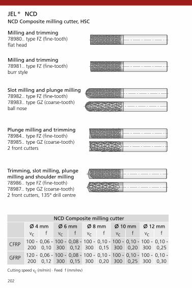
202
X 4 mm X 6 mm X 8 mm X 10 mm X 12 mmvc f vc f vc f vc f vc f
100 - 200
0,06 - 0,10
100 - 300
0,08 - 0,12
100 - 300
0,10 - 0,15
100 - 300
0,10 - 0,20
100 - 300
0,10 - 0,25
120 - 200
0,06 - 0,12
100 - 300
0,08 - 0,15
100 - 300
0,10 - 0,20
100 - 300
0,10 - 0,25
100 - 300
0,10 - 0,30
JEL® NCD
Cutting speed vc (m/min) · Feed f (mm/rev)
NCD Composite milling cutter
CFRP
GFRP
NCD Composite milling cutter, HSC
Milling and trimming78980.. type FZ (fine-tooth)flat head
Milling and trimming78981.. type FZ (fine-tooth)burr style
Slot milling and plunge milling78982.. type FZ (fine-tooth)78983.. type GZ (coarse-tooth)ball nose
Plunge milling and trimming78984.. type FZ (fine-tooth)78985.. type GZ (coarse-tooth)2 front cutters
Trimming, slot milling, plunge milling and shoulder milling78986.. type FZ (fine-tooth)78987.. type GZ (coarse-tooth)2 front cutters, 135° drill centre

203
JEL® NCD
X 4 mm X 6 mm X 8 mm X 10 mmvc f vc f vc f vc f
100 - 200
0,02 - 0,04
100 - 300
0,02 - 0,06
100 - 300
0,02 - 0,08
100 - 300
0,02 - 0,10
100 - 200
0,02 - 0,06
100 - 300
0,02 - 0,08
100 - 300
0,02 - 0,10
100 - 300
0,02 - 0,12
100 - 200
0,02 - 0,04
100 - 300
0,02 - 0,06
100 - 300
0,02 - 0,08
100 - 300
0,02 - 0,10
100 - 200
0,02 - 0,04
100 - 300
0,02 - 0,06
100 - 300
0,02 - 0,08
100 - 300
0,02 - 0,10
NCD Composite multi-tooth milling cutter
NCD Composite multi-tooth milling cutterCutting speed vc (m/min)Feed f (mm/rev)
CFRP
GFRP
CFRP/Al stacks
Honeycombs
Trimming, circular cutting, axial grooving, pocket and slot milling
78989.. helical teeth, pull cutburr style, every second tooth exposedfine chip breaker
78988..straight teethburr style, every second tooth exposedfine chip breaker

204
KOMET® Quatron hi.feed
x dM
ap
x D
x d1min-max
dM = d1max – DdM = d1min – D
ap
x D
fz Y
initial min max max0,10 0,08 0,15 < 0,7 × D
ap aeX D min-max a max max20 30-38 2,8° 0,67 5,025 41-48 2,8° 0,72 5,632 52-62 2,5° 0,88 7,035 56-68 2,5° 0,88 7,042 69-82 2,3° 1,1 8,552 87-100 2,3° 1,1 8,5
Circular interpolation
Axial plunging
Milling cutter dia.
machining dia.
Ramping angle
Application examples

205
KOMET® Quatron hi.feed
ap a
x D
Y
Y
ae
ae/2
ae
Y
Inclined plunging
Plunge milling
Tool offset with optimum coverage
Tool offset for unstable conditions
Application examples

206
x 20 x 25 x 32 x 35 x 42 x 52
P
1.0
2.0
2.1
3.0
4.0
4.1
S
5.0
5.1
M
6.0
6.1
7.0
K
8.0
8.1
9.0
9.1
10.0
10.1
10.2
N
12.0
12.1
13.0
13.1
14.0
H
15.0
16.0
KOMET® Quatron hi.feed
300 0,5-1,2 0,05-0,11 0,5-1,2 0,05-0,11 0,5-1,6 0,06-0,13 0,5-1,6 0,06-0,13 0,5-2,0 0,07-0,15 0,5-2,0 0,07-0,15
250 0,5-1,2 0,05-0,11 0,5-1,2 0,05-0,11 0,5-1,6 0,06-0,13 0,5-1,6 0,06-0,13 0,5-2,0 0,07-0,15 0,5-2,0 0,07-0,15
300 0,5-1,2 0,05-0,11 0,5-1,2 0,05-0,11 0,5-1,6 0,06-0,13 0,5-1,6 0,06-0,13 0,5-2,0 0,07-0,15 0,5-2,0 0,07-0,15
200 0,5-1,2 0,05-0,11 0,5-1,2 0,05-0,11 0,5-1,6 0,06-0,13 0,5-1,6 0,06-0,13 0,5-2,0 0,07-0,15 0,5-2,0 0,07-0,15
180 0,5-1,2 0,05-0,11 0,5-1,2 0,05-0,11 0,5-1,6 0,06-0,13 0,5-1,6 0,06-0,13 0,5-2,0 0,07-0,15 0,5-2,0 0,07-0,15
80 0,5-1,2 0,05-0,11 0,5-1,2 0,05-0,11 0,5-1,6 0,06-0,13 0,5-1,6 0,06-0,13 0,5-2,0 0,07-0,15 0,5-2,0 0,07-0,15
Mat
eria
l gro
upSe
lect
ion:
L.H
. fol
d pa
ge
Cut
ting
spee
d v
c (m
/min
)Feed fz (mm/tooth) Feed fz (mm/tooth)
normalPlunge milling
normalPlunge milling
normalPlunge milling
normalPlunge milling
normalPlunge milling
normalPlunge milling
Guideline values for milling
on request

207
KOMET® Quatron hi.feed
x 20 x 25 x 32 x 35 x 42 x 52
P
1.0
2.0
2.1
3.0
4.0
4.1
S
5.0
5.1
M
6.0
6.1
7.0
K
8.0
8.1
9.0
9.1
10.0
10.1
10.2
N
12.0
12.1
13.0
13.1
14.0
H
15.0
16.0
300 0,5-1,2 0,05-0,11 0,5-1,2 0,05-0,11 0,5-1,6 0,06-0,13 0,5-1,6 0,06-0,13 0,5-2,0 0,07-0,15 0,5-2,0 0,07-0,15
250 0,5-1,2 0,05-0,11 0,5-1,2 0,05-0,11 0,5-1,6 0,06-0,13 0,5-1,6 0,06-0,13 0,5-2,0 0,07-0,15 0,5-2,0 0,07-0,15
300 0,5-1,2 0,05-0,11 0,5-1,2 0,05-0,11 0,5-1,6 0,06-0,13 0,5-1,6 0,06-0,13 0,5-2,0 0,07-0,15 0,5-2,0 0,07-0,15
200 0,5-1,2 0,05-0,11 0,5-1,2 0,05-0,11 0,5-1,6 0,06-0,13 0,5-1,6 0,06-0,13 0,5-2,0 0,07-0,15 0,5-2,0 0,07-0,15
180 0,5-1,2 0,05-0,11 0,5-1,2 0,05-0,11 0,5-1,6 0,06-0,13 0,5-1,6 0,06-0,13 0,5-2,0 0,07-0,15 0,5-2,0 0,07-0,15
80 0,5-1,2 0,05-0,11 0,5-1,2 0,05-0,11 0,5-1,6 0,06-0,13 0,5-1,6 0,06-0,13 0,5-2,0 0,07-0,15 0,5-2,0 0,07-0,15
Guideline values for milling
Mat
eria
l gro
upSe
lect
ion:
L.H
. fol
d pa
ge
Cut
ting
spee
d v
c (m
/min
)
Feed fz (mm/tooth) Feed fz (mm/tooth)
normalPlunge milling
normalPlunge milling
normalPlunge milling
normalPlunge milling
normalPlunge milling
normalPlunge milling
on request
Important: For more application details and safety notes see E 86-87!

208
P25M
K10
/ K
20
BK61
10
BK61
15
BK64
BK74
BK27
15
BK27
25
BK27
30
BK68
BK78
BK80
BK84
25
BK84
40
CK
37
P
1.0
2.0
2.1
3.0
4.0
4.1
S
5.0
5.1
M
6.0
6.1
7.0
K
8.0
8.1
9.0
9.1
10.0
10.1
10.2
N
12.0
12.1
13.0
13.1
14.0
H
15.0
16.0
60-100 100-180 100-180 90-160 120-180 90-160 120-180 90-160 100-180 80-160 180-350
60-100 100-180 100-180 90-160 120-180 90-160 120-180 90-160 100-180 80-160 180-350
60-100 100-180 100-180 90-160 120-180 90-160 120-180 90-160 100-180 80-160 180-350
40-70 60-120 60-120 50-110 120-160 50-110 90-160 50-110 70-130 60-110 160-280
40-70 60-120 60-120 50-110 120-160 50-110 90-160 50-110 70-130 60-110 160-280
– – – – – – – – – – –
20-40 40-60
10-30 40-60
60-140 80-160 80-160 100-180 80-160 70-150 200-260
60-140 80-160 80-160 100-180 80-160 70-150 200-260
60-140 80-160 80-160 100-180 80-160 70-150 200-260
60-150 180-350 150-330 140-250 60-140 120-260 60-140 140-200 250-320
60-150 150-280 120-260 110-200 60-140 120-260 60-140 140-200 250-320
60-150 160-320 140-300 130-230 60-140 120-260 60-140 140-200 250-320
60-150 150-280 120-260 110-200 60-140 120-260 60-140 140-200 250-320
60-150 130-250 110-230 100-180 60-140 120-260 60-140 140-200 250-320
60-150 130-250 110-230 100-180 60-140 120-260 60-140 140-200 250-320
60-100 110-210 90-200 90-150 – – – – –
200-500
200-500
200-500
200-500
200-500
Mat
eria
l gro
upSe
lect
ion:
L.H
. fol
d pa
ge
Cutting speed vc (m/min) Cutting speed vc (m/min)T-slot milling = vc – 50 % T-slot milling = vc – 50 %
uncoated CVD coated PVD PVD coated Cermet
Guideline values for millingKOMET® Indexable insert milling cutter

209
P25M
K10
/ K
20
BK61
10
BK61
15
BK64
BK74
BK27
15
BK27
25
BK27
30
BK68
BK78
BK80
BK84
25
BK84
40
CK
37
P
1.0
2.0
2.1
3.0
4.0
4.1
S
5.0
5.1
M
6.0
6.1
7.0
K
8.0
8.1
9.0
9.1
10.0
10.1
10.2
N
12.0
12.1
13.0
13.1
14.0
H
15.0
16.0
60-100 100-180 100-180 90-160 120-180 90-160 120-180 90-160 100-180 80-160 180-350
60-100 100-180 100-180 90-160 120-180 90-160 120-180 90-160 100-180 80-160 180-350
60-100 100-180 100-180 90-160 120-180 90-160 120-180 90-160 100-180 80-160 180-350
40-70 60-120 60-120 50-110 120-160 50-110 90-160 50-110 70-130 60-110 160-280
40-70 60-120 60-120 50-110 120-160 50-110 90-160 50-110 70-130 60-110 160-280
– – – – – – – – – – –
20-40 40-60
10-30 40-60
60-140 80-160 80-160 100-180 80-160 70-150 200-260
60-140 80-160 80-160 100-180 80-160 70-150 200-260
60-140 80-160 80-160 100-180 80-160 70-150 200-260
60-150 180-350 150-330 140-250 60-140 120-260 60-140 140-200 250-320
60-150 150-280 120-260 110-200 60-140 120-260 60-140 140-200 250-320
60-150 160-320 140-300 130-230 60-140 120-260 60-140 140-200 250-320
60-150 150-280 120-260 110-200 60-140 120-260 60-140 140-200 250-320
60-150 130-250 110-230 100-180 60-140 120-260 60-140 140-200 250-320
60-150 130-250 110-230 100-180 60-140 120-260 60-140 140-200 250-320
60-100 110-210 90-200 90-150 – – – – –
200-500
200-500
200-500
200-500
200-500
Mat
eria
l gro
upSe
lect
ion:
L.H
. fol
d pa
ge
Cutting speed vc (m/min) Cutting speed vc (m/min)T-slot milling = vc – 50 % T-slot milling = vc – 50 %
uncoated CVD coated PVD PVD coated Cermet
Guideline values for millingKOMET® Indexable insert milling cutter
Important: For more application details and safety notes see E 86-87!

210
Q09 Q12 Q15 Q36 Q80
P
1.0
2.0
2.1
3.0
4.0
4.1
S
5.0
5.1
M
6.0
6.1
7.0
K
8.0
8.1
9.0
9.1
10.0
10.1
10.2
N
12.0
12.1
13.0
13.1
14.0
H
15.0
16.0
0,08-0,40 0,04-0,12 0,05-0,20 0,05-0,12 0,04-0,12 0,08-0,35 0,06-0,30 0,06-0,30 0,06-0,30
0,08-0,40 0,04-0,12 0,05-0,20 0,05-0,12 0,04-0,12 0,08-0,35 0,06-0,30 0,06-0,30 0,06-0,30
0,08-0,40 0,04-0,12 0,05-0,20 0,05-0,12 0,04-0,12 0,08-0,35 0,06-0,30 0,06-0,30 0,06-0,30
0,08-0,30 0,04-0,12 0,05-0,20 0,05-0,12 0,04-0,12 0,08-0,25 0,06-0,25 0,06-0,25 0,06-0,25
0,05-0,25 0,04-0,12 0,05-0,20 0,05-0,12 0,04-0,12 0,08-0,25 0,06-0,25 0,06-0,25 0,06-0,25
– – – – – – – – –
0,05-0,20 0,04-0,10 0,04-0,10 0,04-0,10
0,05-0,20 0,04-0,10 0,04-0,10 0,04-0,10
0,05-0,20 0,05-0,20 0,05-0,10 0,05-0,15 0,05-0,15 0,05-0,15 0,05-0,15
0,05-0,20 0,05-0,20 0,05-0,10 0,05-0,15 0,05-0,15 0,05-0,15 0,05-0,15
0,05-0,20 0,05-0,20 0,05-0,10 0,05-0,15 0,05-0,15 0,05-0,15 0,05-0,15
0,08-0,40 0,04-0,15 0,05-0,20 0,05-0,15 0,04-0,15 0,10-0,30 0,10-0,30 0,10-0,30 0,10-0,30 0,25-0,35
0,08-0,40 0,04-0,15 0,05-0,20 0,05-0,15 0,04-0,15 0,10-0,30 0,10-0,30 0,10-0,30 0,10-0,30 0,25-0,35
0,08-0,40 0,04-0,15 0,05-0,20 0,05-0,15 0,04-0,15 0,10-0,30 0,10-0,30 0,10-0,30 0,10-0,30 0,25-0,35
0,08-0,30 0,04-0,15 0,05-0,20 0,05-0,15 0,04-0,15 0,10-0,30 0,10-0,30 0,10-0,30 0,10-0,30 0,25-0,35
0,08-0,30 0,04-0,15 0,05-0,20 0,05-0,15 0,04-0,15 0,10-0,30 0,10-0,30 0,10-0,30 0,10-0,30 0,25-0,35
0,08-0,30 0,04-0,15 0,05-0,20 0,05-0,15 0,04-0,15 0,10-0,30 0,10-0,30 0,10-0,30 0,10-0,30 0,25-0,35
0,08-0,30 0,04-0,15 0,05-0,20 0,05-0,15 0,04-0,15 0,10-0,30 0,10-0,30 0,10-0,30 0,10-0,30 0,25-0,35
0,05-0,40 0,05-0,15 0,05-0,20 0,05-0,25 0,05-0,15 0,10-0,45 0,10-0,45 0,10-0,45 0,10-0,45
0,05-0,30 0,05-0,15 0,05-0,20 0,05-0,25 0,05-0,15 0,10-0,45 0,10-0,45 0,10-0,45 0,10-0,45
0,05-0,30 0,05-0,15 0,05-0,20 0,05-0,25 0,05-0,15 0,10-0,45 0,10-0,45 0,10-0,45 0,10-0,45
0,10-0,50 0,05-0,15 0,05-0,20 0,05-0,25 0,05-0,15 0,10-0,45 0,10-0,45 0,10-0,45 0,10-0,45
0,10-0,50 0,05-0,15 0,05-0,20 0,05-0,25 0,05-0,15 0,10-0,45 0,10-0,45 0,10-0,45 0,10-0,45
Guideline values for millingKOMET® Indexable insert milling cutter
Mat
eria
l gro
upSe
lect
ion:
L.H
. fol
d pa
ge
Feed fz (mm/tooth) Feed fz (mm/tooth)
Face milling cutter
T-slot milling cutter
Chamfer milling cutter
Circular milling cutter
T-slot milling cutter
Corner milling cutter
Shell end face milling cutter
End milling cutter
Copying end milling cutter
Arbor face milling cutter hi.aeQ

211
Q09 Q12 Q15 Q36 Q80
P
1.0
2.0
2.1
3.0
4.0
4.1
S
5.0
5.1
M
6.0
6.1
7.0
K
8.0
8.1
9.0
9.1
10.0
10.1
10.2
N
12.0
12.1
13.0
13.1
14.0
H
15.0
16.0
0,08-0,40 0,04-0,12 0,05-0,20 0,05-0,12 0,04-0,12 0,08-0,35 0,06-0,30 0,06-0,30 0,06-0,30
0,08-0,40 0,04-0,12 0,05-0,20 0,05-0,12 0,04-0,12 0,08-0,35 0,06-0,30 0,06-0,30 0,06-0,30
0,08-0,40 0,04-0,12 0,05-0,20 0,05-0,12 0,04-0,12 0,08-0,35 0,06-0,30 0,06-0,30 0,06-0,30
0,08-0,30 0,04-0,12 0,05-0,20 0,05-0,12 0,04-0,12 0,08-0,25 0,06-0,25 0,06-0,25 0,06-0,25
0,05-0,25 0,04-0,12 0,05-0,20 0,05-0,12 0,04-0,12 0,08-0,25 0,06-0,25 0,06-0,25 0,06-0,25
– – – – – – – – –
0,05-0,20 0,04-0,10 0,04-0,10 0,04-0,10
0,05-0,20 0,04-0,10 0,04-0,10 0,04-0,10
0,05-0,20 0,05-0,20 0,05-0,10 0,05-0,15 0,05-0,15 0,05-0,15 0,05-0,15
0,05-0,20 0,05-0,20 0,05-0,10 0,05-0,15 0,05-0,15 0,05-0,15 0,05-0,15
0,05-0,20 0,05-0,20 0,05-0,10 0,05-0,15 0,05-0,15 0,05-0,15 0,05-0,15
0,08-0,40 0,04-0,15 0,05-0,20 0,05-0,15 0,04-0,15 0,10-0,30 0,10-0,30 0,10-0,30 0,10-0,30 0,25-0,35
0,08-0,40 0,04-0,15 0,05-0,20 0,05-0,15 0,04-0,15 0,10-0,30 0,10-0,30 0,10-0,30 0,10-0,30 0,25-0,35
0,08-0,40 0,04-0,15 0,05-0,20 0,05-0,15 0,04-0,15 0,10-0,30 0,10-0,30 0,10-0,30 0,10-0,30 0,25-0,35
0,08-0,30 0,04-0,15 0,05-0,20 0,05-0,15 0,04-0,15 0,10-0,30 0,10-0,30 0,10-0,30 0,10-0,30 0,25-0,35
0,08-0,30 0,04-0,15 0,05-0,20 0,05-0,15 0,04-0,15 0,10-0,30 0,10-0,30 0,10-0,30 0,10-0,30 0,25-0,35
0,08-0,30 0,04-0,15 0,05-0,20 0,05-0,15 0,04-0,15 0,10-0,30 0,10-0,30 0,10-0,30 0,10-0,30 0,25-0,35
0,08-0,30 0,04-0,15 0,05-0,20 0,05-0,15 0,04-0,15 0,10-0,30 0,10-0,30 0,10-0,30 0,10-0,30 0,25-0,35
0,05-0,40 0,05-0,15 0,05-0,20 0,05-0,25 0,05-0,15 0,10-0,45 0,10-0,45 0,10-0,45 0,10-0,45
0,05-0,30 0,05-0,15 0,05-0,20 0,05-0,25 0,05-0,15 0,10-0,45 0,10-0,45 0,10-0,45 0,10-0,45
0,05-0,30 0,05-0,15 0,05-0,20 0,05-0,25 0,05-0,15 0,10-0,45 0,10-0,45 0,10-0,45 0,10-0,45
0,10-0,50 0,05-0,15 0,05-0,20 0,05-0,25 0,05-0,15 0,10-0,45 0,10-0,45 0,10-0,45 0,10-0,45
0,10-0,50 0,05-0,15 0,05-0,20 0,05-0,25 0,05-0,15 0,10-0,45 0,10-0,45 0,10-0,45 0,10-0,45
Guideline values for millingKOMET® Indexable insert milling cutter
Important: For more application details and safety notes see E 86-87!
Mat
eria
l gro
upSe
lect
ion:
L.H
. fol
d pa
ge
Feed fz (mm/tooth) Feed fz (mm/tooth)
Face milling cutter
T-slot milling cutter
Chamfer milling cutter
Circular milling cutter
T-slot milling cutter
Corner milling cutter
Shell end face milling cutter
End milling cutter
Copying end milling cutter
Arbor face milling cutter hi.aeQ

212
D
a p
b
a e
vf
n
fz
vf = fz × z × n (mm/min)
ae =
ap =
b =
D =
fz =
n =
kc =
Pe =
vc =
vf =
z =
h =
n =vc × 1000
p × D(min–1)
vc =n × p × D
1000(m/min)
ap × ae × vf × kc60 × 106 × h
Pe = (kW)
Feed rate:
Spindle speed:
Cutting speed:
Power requirement:
milling width in mm
cutting depth in mm
chip width in mm
tool diameter in mm
feed/tooth in mm
speed in min–1
specific cutting force in N/mm²
power requirement in KW
cutting speed in m/min
feed rate in mm/min
tooth load
working angle
Specific cutting force kc (N/mm²)KOMET® Calculation information

213
HB 0,1 0,2 0,3 0,4
P
150 3200 2700 2450 2300
190 3550 3000 2750 2550
250 3900 3300 3000 2800
3550 3000 2750 2550
200 - 250 3900 3300 3000 2800
275 - 325 4300 3600 3300 2100
325 - 375 4600 3900 3600 3300
375 - 425 4850 4100 3750 3500
425 - 475 5000 4300 3900 3700
M
135 - 175 3100 3600 2350 2200
175 - 225 4150 3500 3200 3000
275 - 325 4700 4000 3650 3400
375 - 425 5300 4500 4100 3850
135 - 425 4150 3500 3200 3000
K
2850 2400 2200 2050
150 - 200 3150 2650 2400 2250
200 - 250 3400 2900 2650 2450
250 - 300 3700 3200 2900 2700
110 - 145 2000
200 - 250 2000
180 1400
250 1800
160 1500
250 2250
400 3500
Workpiece materialBrinell-
hardnessFeed
fz (mm/tooth)
Carbon steel 0,2%C
Carbon steel 0,45%C
Carbon steel 0,83%C
Alloy steel up to 200
Stainless steel, ferritic
Stainless steel, martensitic
Stainless steel, austenitic
Cast steel, carbon up to 150
Cast steel, alloy
Malleable iron, ferritic
Malleable iron, perlitic
Grey cast iron, low tensile strengh
Grey cast iron, high tensile strengh, alloy
Spheroidal graphite cast iron, ferritic
Spheroidal graphite cast iron, perlitic
Chill cast iron
Specific cutting force kc (N/mm²)KOMET® Calculation information

214
aeDa² – Di²
4 (Da – Dwz)=
vf(Da – Dwz) × n × zeff × fz
Da=
Da
DiDwz
ae
Circular milling, internal
R = workpiece radius in mmr = milling cutter radius in mmar = radial cutting depth in mm = approach angle in °hm = average chip thickness in mmn = spindle speed in min–1
z = number of teeth (effectively cutting)
ae > radial material removal
radial
materia
l removal
KOMET® Calculations for circular milling

215
Da
Di Dwz
ae
aeDa² – Di²
4 (Di – Dwz)=
vf(Di – Dwz) × n × zeff × fz
Di=
The average chip thickness is determined by considering workpiece and tool geometry data. The total cutting time must allow for the entry and exit times. Axial "cham-bering" is also possible with these interpolating milling cutters.
Circular milling, external
ae < radial material removal
radial
materia
l removal
KOMET® Calculations for circular milling

216
��
�
�
�
�
a
Lx D
Single angled entryIt it is not possible to obtain the required slot depth by a single entry, this is achieved by entering more than once.
slot length
KOMET® Instructions for slot milling into the solid

217
X D L ap a
max max9,5 91,5 8 5°
10,0 91,5 8 5°
12,0 14,4 9 32°
14,0 12,8 9 35°
16,0 33,6 9 15°
20,0 128,7 9 4°
25,0 128,7 9 4°
32,0 343,0 9 1,4°
40,0 (F51 50181) 186,0 15 3°
��
�
�
�
�
a –0
,8
0,8
Milling dia.
Max. angle of entry
in relation to diameter d1
Multiple entryIt should be noted that there must be an allowance of 0,8 mm when the milling cutter is reversed. If this allowance is not made, the tool may be damaged or destroyed.
KOMET® Instructions for slot milling into the solid

218
DIH
AR
T R
EAM
AX
® T
S
DIH
AR
T R
EAM
AX
®
DIH
AR
T M
on
om
ax®
DIH
AR
T® F
ullm
ax
DIH
AR
T® D
uo
max
DIH
AR
T® M
icro
Set
Sys
tem
E 220 E 220 E 220 E 220 E 220 E 220 E 220
E 222 E 224 E 225 E 226 E 228 E 231 E 232
E 238 E 238 E 238 E 238 E 236 E 238 E 238
E 240 E 240 E 240 E 240 E 236 E 240 E 240
E 234 - 235
E 242 - 245
E 246 - 247
E 248 - 249
E 250 - 251
Index Reaming
Tool selection
Assembly instructions
Guideline values cutting speed vc
Guideline values feed fz
Assembly instructions DIHART DAH® compensating holder
Cutting geometry ASG, cutting materials and coatings
Types of tool wear
Problem – possible causes – solutions
Measuring
DIH
AR
T® S
olid
car
bid
e re
amer
DIH
AR
T® C
utt
ing
rin
g
DIH
AR
T® I
nse
rt r
eam
ing

219
DIH
AR
T R
EAM
AX
® T
S
DIH
AR
T R
EAM
AX
®
DIH
AR
T M
on
om
ax®
DIH
AR
T® F
ullm
ax
DIH
AR
T® D
uo
max
DIH
AR
T® M
icro
Set
Sys
tem
E 220 E 220 E 220 E 220 E 220 E 220 E 220
E 222 E 224 E 225 E 226 E 228 E 231 E 232
E 238 E 238 E 238 E 238 E 236 E 238 E 238
E 240 E 240 E 240 E 240 E 236 E 240 E 240
E 234 - 235
E 242 - 245
E 246 - 247
E 248 - 249
E 250 - 251
Index Reaming
DIH
AR
T® S
olid
car
bid
e re
amer
DIH
AR
T® C
utt
ing
rin
g
DIH
AR
T® I
nse
rt r
eam
ing
Special tools

220
x 1
,400
x 2
,960
x 4
,000
x 5
,600
x 9
,600
x 1
0,15
9x
12,
000
x 1
2,70
0x
17,
600
x 1
8,00
0x
18,
899
x 2
0,05
0x
20,
100
x 2
5,89
9x
40,
000
x 5
0,00
0x
60,
600
x 6
5,00
0x
110
,599
x 1
39,5
99x
300
,599
REAMAX® TS
REAMAX®
Monomax®
Fullmax
DIHART® Tool SelectionOverview standard reamers
Tool Tool attachement
Cylindrical shankDAH®
Cylindrical shank
Cylindrical shankMorse taper
expandable
Cylindrical shank
Solid carbide reamer
Cylindrical shank
Cylindrical shankDAH®ABS®Cutting ring
+ Duomax

221
x 1,40 – 5,59 mm
x 5,60 – 11,99 mm
x 12,00 – 17,99 mm
x 18 – 40 mm
x 40 – 65 mm
x 65 – 110 mm
IT 5
– IT
6
Monomax® Monomax® REAMAX® TS REAMAX® TS
IT 7
Monomax® REAMAX® REAMAX® TS REAMAX® TS
M IT
8
REAMAX® REAMAX® REAMAX® TS
DIHART® Tool Selection
Solid carbide reamer
Cutting ring+ Duomax
Solid carbide reamer
Cutting ring+ Duomax
Solid carbide reamer
Solid carbide reamer
Cutting ring+ Duomax
Tool recommendation
IT-Tolerance class see page 6.

222
DIHART REAMAX® TS
6
1
2
3
M
18,000 – 19,999 1,5 Nm
20,000 – 21,999 2,5 Nm
22,000 – 26,999 4 Nm
27,000 – 34,999 5 Nm
35,000 – 41,999 6 Nm
42,000 – 51,999 10 Nm
52,000 – 65,000 13 Nm
1
2
3
1
2
3
4
5
Assembly instructions
Starting torque MDia. range
Clean taper/face contact thor-oughly (grease free). Screw pull stud into reaming head and tighten with open-end wrench .
Open clamping jaws with key . Insert reaming head .
Close clamping jaws with key , noting recommended torque.When inserting the reaming head this is drawn into its final position by closing the clamping jaws .
When removing the reaming head this is pressed out of its position by the clamping jaws which al-lows it to be easily removed from the holder: open the clamping jaws with the key , emove the reaming head .
Adjusting to compensate for wear
The smallest bore tolerances of up to IT4 can be achieved by readjust-ing with the hexagonal key .

223
DIHART REAMAX® TS
1
2
Important: For more application details and safety notes see E 86-87!
Adjusting:
• Set the µm dial by adjusting the bezel position.
• Determine the highest setting on the dial by turning the tool.
• Turn the adjustment screw clockwise using an Allen key , correcting the concentricity.
Over tension by approx. 5 µm.
• Engage the opposite adjustment screws and drive back the tool by the specified overtension value.
• Engage the two other adjustment screws.
• Align all 4 adjustment screws until concentricity is < 2 µm.
Please note:
• Only unscrew the adjustment screws by a max of ½ to 1 rotation.
• Never use the holder without the reamer head clamped and then only when the adjustment screws are tightened.
Operating Instruction DAH® Zero

224
DIHART REAMAX®
12,000 – 15,999 4-5 Nm
16,000 – 21,999 6-7 Nm
22,000 – 25,999 10-12 Nm
26,000 – 32,000 18-20 Nm
32,001 – 40,000 26-28 Nm
5
5
M3
3
3
Assembly instructions
Clean taper/face contact thor-oughly (grease free). Apply light grease on tie bar thread .
Locate tie bar on insert and holder. Important note: for nominal size 3, 4 and 5, fit with marking on tie bar and insert aligned.
Draw in tie bar with the clamping nut. Before tightening, turn insert and tie bar clockwise until it stops.Tighten the clamping nut as far as possible using the torque key to the specified starting torque M.
Removing the replaceable insert:Loosen the clamping screw.Pull tie bar from holder and insert.
Locate operating key in insert and loosen insert by turning.
Starting torque MDia. range

225
DIHART Monomax®
15A.11.200xx
15A.10.200xx
Central coolant outlet
Lateral coolant outlet
Taper screw Reamer
Taper screw Reamer

226
+
Assembly instructions on holder for through hole machining
Please observe the marking on holder and cutting ring, check alignment of the coolant bores.
The position for the drive pins is marked with a lobe or in red. Before tightening and adjusting turn the cutting ring against the direction of machining until hitting the drive pins.Lobe
(measuring tooth)
DIHART® Cutting Ring
Arrow markings:light greaseface surfaces on holder and cutting ring are grease-free
Adjust the diameter to the middle of the tolerance (counter-clockwise thread).
The diameter can only be measured at the marked cutting edges due to unequal angular position!
Measure the diameterIf the diameter was set too large, the conical ring must be loosened and the cutting ring readjusted.
Lobe (measuring tooth)

227
M
60 90 – 110 Nm
61 – 79 120 – 140 Nm
80 – 100 180 – 220 Nm
+
Assembly instructions on holder for blind hole machining
Screw the nut onto the holder with the smooth face against the bush. Mount the cutting ring with the conical screw. After fastening the conical screw check that there is space between bush and ring. Fasten conical screw according to index table.
The position for the drive pins is marked with a lobe or in red.Before tightening and adjusting turn the cutting ring against the direction of machining until hitting the drive pin.
DIHART® Cutting Ring
Starting torque M
Dia. range
Arrow markings:light greaseface surfaces on holder and cutting ring are grease-free
Please observe the marking on holder and cutting ring, check alignment of the coolant bores.Adjust the diameter to the middle of the tolerance.
The diameter can only be meas-ured at the marked cutting edges due to unequal angular position!
Measure the diameterIf the diameter was set too large, the nut must be loosened and the cutting ring readjusted.
Lobe (measuring tooth)
Lobe (measuring tooth)

228
DIHART® Duomax
+
Assembly instructions on holder for through hole machining
Arrow markings:light greaseface surfaces on holder and Duomax are grease-free
Please observe the marking on holder and Duomax , check align-ment of the coolant bores.
Positioning of the drive pins to the right of letter A (the measuring tooth is located at letter A and is also marked on the holder with a spot).Before tightening and adjusting turn the Duomax against the direction of machining until hitting the drive pins.
Measuring tooth A
Adjust the diameter to the middle of the tolerance (counter-clockwise thread).
The diameter can only be meas-ured at the marked cutting edges (measuring tooth A) due to un-equal angular position!
If the diameter was set too large, the conical ring must be loosened and the Duomax readjusted.
Measuring tooth A
Measure the diametersee page 202

229
M
DIHART® Duomax
61 – 79 120 – 140 Nm
80 – 100 180 – 220 Nm
+
Assembly instructions on holder for blind hole machining
Screw the nut onto the holder with the smooth face against the bush. Mount the Duomax with the conical screw. After fastening the conical screw check that there is space between bush and Duomax. Fasten conical screw according to index table.
Starting torque M
Dia. range
Please observe the marking on holder and Duomax, check alignment of the coolant bores. Adjust the diameter to the middle of the tolerance.
The diameter can only be measured at the marked cutting edges (measuring tooth A) due to unequal angular position!
If the diameter was set too large, the nut must be loosened and the Duomax readjusted.
Measuring tooth A
Measuring tooth A
Measure the diametersee page 202
Arrow markings:light greaseface surfaces on holder and Duomax are grease-free
Positioning of the drive pins to the right of letter A (the measuring tooth is located at letter A and is also marked on the holder with a spot). Before tightening and adjusting turn the Duomax against the direction of machining until hitting the drive pins.

230
DIHART® Duomax
31
2
45
A
Assembly instructions inserts
Cleaning: Make sure that the insert seats and inserts are absolutely clean/grease-free. If necessary, remove tiny dust particles with compressed air!
Measuring the diameter:The measuring tooth is located at letter A and is also marked on the holder with a spot .
Montage:
• All inserts and insert seats are marked with letters . This ensures correct assignment to the insert seat.
• The number markings ensure that all inserts are positioned correctly.
• Tighten the screw (order no. N00 57710)
to 2.5 Nm. Torque wrench order no. L05 00940
Caution!• Uneven angle division !• There are 2 cutters 180° opposite = measuring tooth A.• Measure the diameter at the front of the cutter (due to tapering, see illustration).• Avoid damaging the cutters• When turning the insert, the
diameter must be readjusted.• Delivery status: Duomax with mounted inserts.

231
4
3
12
5
6
A
Assembly instructions inserts
Cleaning: Make sure that the insert seats and indexable inserts are absolutely clean/grease-free. If necessary, remove tiny dust particles with compressed air!
Measuring the diameter:The measuring tooth is located at letter A and is also marked on the holder with a spot . If the diameter is too large, loosen the conical screw and turn it to the right to set the correct diameter. The conical screw does not have to be removed completely !
Assembly:• All indexable inserts and
insert seats are marked with letters . This en-sures correct assignment to the insert seat.
• The number markings ensure that all indexable inserts are positioned correctly.
•Tighten the screw (order no. N00 57710)
to 2.5 Nm. Torque wrench order no. L05 00940
Caution!• Uneven angle division !• There are 2 cutters 180° op-
posite = measuring tooth A.• Measure the diameter at the
front of the cutter (due to tapering, see illustration).
• Avoid damaging the cutters.• When turning the indexable in-
sert on an adjustable carrier, the diameter must be readjusted.
DIHART® Insert Reaming

232
DIHART® MicroSet System
1
2
3
Assembly parts (Fig. 1) indexable insert clamping screw
Setting machining dia. adjusting wedge differential screw
Setting conicity adjusting wedge differential screw
Fit the indexable insert:Make sure that the insert seat is clean. Place the indexable insert into the insert seat and tighten the clamping screw only slightly.
Use TORX Plus® torque wrench (2,25 Nm) (Fig.2).
Reference dia. as reference di-mension “0” for setting the ma-chining dia. and conicity (Fig. 3), reference dia. is marked on tool.
Assembly instructions

233
4
5
6
DIHART® MicroSet SystemAssembly instructions
Preset the machining dia. (Fig. 4) and conicity (Fig. 5):Use an Allen key (width across flats SW2) to turn the differential screws and until the indexable insert is set to approx. 10 µm below the desired
machining dia. and approx. 25 µm over the reference dia.
Secure the insert:Use a TORX Plus® torque wrench (2,25 Nm) to secure the indexable insert at the preset tightening torque (Fig. 2).
Set the final machining dia. (Fig. 4) and conicity (Fig 5):When tightened, the indexable insert is set to the machining diameter and the specified conicity using the differential screws and .
Tool after setting (Fig 6).

234
2
M
4
2
DAHx d163 7 – 9 Nm
81 7 – 9 Nm
115 25 – 35 Nm
Assembly instructions
Clean grinding surfaces thoroughlydry and free of grease.
Pre-load evenly with the 6 as-sembling screws (pressing the spring washer level)
DIHART DAH® Compensating Holder
Adjusting the DAH® must be done in the machine on the spindle where the tool will be in use afterwards!
Determine the highest point by ro-tating (largest concentricity error). Rotate the threaded pin to the highest point. Correct half of the measured runout error by insert-ing the thread pin . Repeat this procedure until the runout error is < 5 µ.
Center the indicator on the gauge line.
Tighten the assembling screw cross-wise. Please observe the specified starting torque M in the index-table. After fastening, fix the adjusting ring by locking the thread pin .
Finally check the runout once more. «should be» < 5 µ
Starting torque M

235
DIHART DAH® 50 HS
In comparison to previous solutions the hydro-expansion chuck is integrated into the new DIHART® compensating holders. This means one less interface.
Four adjustable screws allow rapid and precise adjustment of the concentricity of the multiple blade reamer, reducing concentricity errors to virtually zero. The extremely slim design of these new compensating holders ensures that they fit easily into practically all tool magazines.
The DIHART DAH® 50 HS compensating holders enable the concentricity of a tool to be adjusted with µ-precision at the bezel position, thereby eliminating any machine spindle error.
Simple handling – reduced machine idle times
Connection on tool-side with hydro-expansion chuck
Simple, time-saving control using adjustment ring with adjustment screw
Alignment module:1 adjustment ring, 4 adjustment screws
Tightening screwfor clamping tool

236
Z4x 2,97 - 4,05
Z4x 4,06 - 6,05
Z6x 6,06 - 7,55
Z6x 7,56 - 12,05
Z6x 12,06 - 16,05
Z6x 16,06 - 20,05
vc (m/min)
fz fz fz fz fz fz
min - max min - max min - max min-max min-max min-max min-max
P
1.0
2.0
2.1
3.0
4.0
4.1
S
5.0
5.1
M
6.0
6.1
7.0
K
8.0
8.1
9.0
9.1
10.0
10.1
10.2
N
12.0
12.1
13.0
13.1
14.0
H
15.0
16.0
DIHART® Fullmax
P S M K N 0,10-0,20 0,10-0,20 0,20 0,20 0,20-0,30 0,30
Hbis HRC48 0,10-0,20 0,10-0,20 0,20 0,20 0,20 0,20bis HRC62 0,10 0,10 0,10 0,10 0,20 0,20
180 - 250 0,100 - 0,200 0,125 - 0,250 0,150 - 0,250 0,175 - 0,300 0,200 - 0,330 0,230 - 0,370180 - 250 0,100 - 0,200 0,125 - 0,250 0,150 - 0,250 0,175 - 0,300 0,200 - 0,330 0,230 - 0,370180 - 250 0,100 - 0,200 0,125 - 0,250 0,150 - 0,250 0,175 - 0,300 0,200 - 0,330 0,230 - 0,370180 - 250 0,100 - 0,200 0,125 - 0,250 0,150 - 0,250 0,175 - 0,300 0,200 - 0,330 0,230 - 0,370180 - 250 0,100 - 0,200 0,125 - 0,250 0,150 - 0,250 0,175 - 0,300 0,200 - 0,330 0,230 - 0,370
40 - 60 0,075 - 0,125 0,100 - 0,150 0,100 - 0,175 0,100 - 0,175 0,125 - 0,200 0,130 - 0,23030 - 60 0,075 - 0,125 0,100 - 0,150 0,100 - 0,175 0,100 - 0,175 0,125 - 0,200 0,130 - 0,23040 - 80 0,075 - 0,125 0,100 - 0,150 0,100 - 0,175 0,100 - 0,175 0,125 - 0,200 0,130 - 0,23040 - 60 0,075 - 0,125 0,100 - 0,150 0,100 - 0,175 0,100 - 0,175 0,125 - 0,200 0,130 - 0,230
0,075 - 0,125 0,100 - 0,150 0,100 - 0,175 0,100 - 0,175 0,125 - 0,200 0,130 - 0,230120 - 180 0,100 - 0,200 0,125 - 0,250 0,150 - 0,250 0,175 - 0,300 0,200 - 0,330 0,230 - 0,370
200 - 250 0,100 - 0,200 0,125 - 0,250 0,150 - 0,250 0,175 - 0,300 0,200 - 0,330 0,230 - 0,370
60 - 120 0,100 - 0,200 0,125 - 0,250 0,150 - 0,250 0,175 - 0,300 0,200 - 0,330 0,230 - 0,370
100 - 250 0,100 - 0,200 0,125 - 0,250 0,150 - 0,250 0,175 - 0,300 0,200 - 0,330 0,230 - 0,37080 - 150 0,075 - 0,125 0,100 - 0,150 0,100 - 0,175 0,100 - 0,175 0,125 - 0,200 0,130 - 0,230
30 - 50 0,035 - 0,075 0,040 - 0,100 0,050 - 0,100 0,050 - 0,100 0,052 - 0,130 0,080 - 0,130
Mat
eria
l gro
upSe
lect
ion:
L.H
. fol
d pa
ge
Cutting speed Feed Feed
(mm/tooth)
(mm/tooth)
(mm/tooth)
(mm/tooth)
(mm/tooth)
(mm/tooth)
Guideline values for reaming – specially for DIHART® Fullmax
Reaming allo wance in diameter (mm)

237
Z4x 2,97 - 4,05
Z4x 4,06 - 6,05
Z6x 6,06 - 7,55
Z6x 7,56 - 12,05
Z6x 12,06 - 16,05
Z6x 16,06 - 20,05
vc (m/min)
fz fz fz fz fz fz
min - max min - max min - max min-max min-max min-max min-max
P
1.0
2.0
2.1
3.0
4.0
4.1
S
5.0
5.1
M
6.0
6.1
7.0
K
8.0
8.1
9.0
9.1
10.0
10.1
10.2
N
12.0
12.1
13.0
13.1
14.0
H
15.0
16.0
DIHART® Fullmax
P S M K N 0,10-0,20 0,10-0,20 0,20 0,20 0,20-0,30 0,30
Hbis HRC48 0,10-0,20 0,10-0,20 0,20 0,20 0,20 0,20bis HRC62 0,10 0,10 0,10 0,10 0,20 0,20
180 - 250 0,100 - 0,200 0,125 - 0,250 0,150 - 0,250 0,175 - 0,300 0,200 - 0,330 0,230 - 0,370180 - 250 0,100 - 0,200 0,125 - 0,250 0,150 - 0,250 0,175 - 0,300 0,200 - 0,330 0,230 - 0,370180 - 250 0,100 - 0,200 0,125 - 0,250 0,150 - 0,250 0,175 - 0,300 0,200 - 0,330 0,230 - 0,370180 - 250 0,100 - 0,200 0,125 - 0,250 0,150 - 0,250 0,175 - 0,300 0,200 - 0,330 0,230 - 0,370180 - 250 0,100 - 0,200 0,125 - 0,250 0,150 - 0,250 0,175 - 0,300 0,200 - 0,330 0,230 - 0,370
40 - 60 0,075 - 0,125 0,100 - 0,150 0,100 - 0,175 0,100 - 0,175 0,125 - 0,200 0,130 - 0,23030 - 60 0,075 - 0,125 0,100 - 0,150 0,100 - 0,175 0,100 - 0,175 0,125 - 0,200 0,130 - 0,23040 - 80 0,075 - 0,125 0,100 - 0,150 0,100 - 0,175 0,100 - 0,175 0,125 - 0,200 0,130 - 0,23040 - 60 0,075 - 0,125 0,100 - 0,150 0,100 - 0,175 0,100 - 0,175 0,125 - 0,200 0,130 - 0,230
0,075 - 0,125 0,100 - 0,150 0,100 - 0,175 0,100 - 0,175 0,125 - 0,200 0,130 - 0,230120 - 180 0,100 - 0,200 0,125 - 0,250 0,150 - 0,250 0,175 - 0,300 0,200 - 0,330 0,230 - 0,370
200 - 250 0,100 - 0,200 0,125 - 0,250 0,150 - 0,250 0,175 - 0,300 0,200 - 0,330 0,230 - 0,370
60 - 120 0,100 - 0,200 0,125 - 0,250 0,150 - 0,250 0,175 - 0,300 0,200 - 0,330 0,230 - 0,370
100 - 250 0,100 - 0,200 0,125 - 0,250 0,150 - 0,250 0,175 - 0,300 0,200 - 0,330 0,230 - 0,37080 - 150 0,075 - 0,125 0,100 - 0,150 0,100 - 0,175 0,100 - 0,175 0,125 - 0,200 0,130 - 0,230
30 - 50 0,035 - 0,075 0,040 - 0,100 0,050 - 0,100 0,050 - 0,100 0,052 - 0,130 0,080 - 0,130
Mat
eria
l gro
upSe
lect
ion:
L.H
. fol
d pa
ge
Cutting speed Feed Feed
(mm/tooth)
(mm/tooth)
(mm/tooth)
(mm/tooth)
(mm/tooth)
(mm/tooth)
Important: For more application details and safety notes see E 86-87!
Guideline values for reaming – specially for DIHART® Fullmax
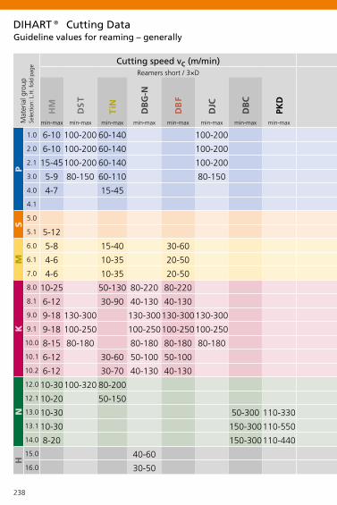
238
min-max min-max min-max min-max min-max min-max min-max min-max min-max min-max min-max min-max min-max min-max min-max min-max
P
1.0
2.0
2.1
3.0
4.0
4.1
S
5.0
5.1
M
6.0
6.1
7.0
K
8.0
8.1
9.0
9.1
10.0
10.1
10.2
N
12.0
12.1
13.0
13.1
14.0
H
15.0
16.0
HM
DS
T
TiN
DB
G-N
DB
F
DJC
DB
C
PKD
HM
DS
T
TiN
DB
G-N
DB
F
DJC
DB
C
PKD
6-10 100-200 60-140 100-200 6-10 80-160 60-120 80-160
6-10 100-200 60-140 100-200 6-10 80-160 60-120 80-160
15-45100-200 60-140 100-200 15-45 80-160 60-120 80-160
5-9 80-150 60-110 80-150 5-9 80-120 60-90 80-120
4-7 15-45 4-7 15-45
5-12 5-12
5-8 15-40 30-60 5-8 15-40 30-60
4-6 10-35 20-50 4-6 10-35 20-50
4-6 10-35 20-50 4-6 10-35 20-50
10-25 50-130 80-220 80-220 10-25 50-100 80-150 80-150
6-12 30-90 40-130 40-130 6-12 30-90 40-100 40-100
9-18 130-300 130-300130-300130-300 9-18 120-180 120-180 120-180 120-180
9-18 100-250 100-250100-250100-250 9-18 100-160 100-160 100-160 100-160
8-15 80-180 80-180 80-180 80-180 8-15 80-150 80-150 80-150 80-150
6-12 30-60 50-100 50-100 6-12 30-60 50-100 50-100 50-100
6-12 30-70 40-130 40-130 6-12 30-70 40-130 40-130 40-130
10-30100-320 80-200 10-30 100-200 80-150
10-20 50-150 10-20 50-120
10-30 50-300 110-330 10-30 50-240 100-240
10-30 150-300110-550 10-30 150-250 100-300
8-20 150-300110-440 8-20 150-250 100-250
40-60 40-60
30-50 30-50
Mat
eria
l gro
upSe
lect
ion:
L.H
. fol
d pa
ge
Cutting speed vc (m/min) Cutting speed vc (m/min)Reamers short / 3×D Reamers long / 5×D
Guideline values for reaming – generallyDIHART® Cutting Data

239
min-max min-max min-max min-max min-max min-max min-max min-max min-max min-max min-max min-max min-max min-max min-max min-max
P
1.0
2.0
2.1
3.0
4.0
4.1
S
5.0
5.1
M
6.0
6.1
7.0
K
8.0
8.1
9.0
9.1
10.0
10.1
10.2
N
12.0
12.1
13.0
13.1
14.0
H
15.0
16.0
HM
DS
T
TiN
DB
G-N
DB
F
DJC
DB
C
PKD
HM
DS
T
TiN
DB
G-N
DB
F
DJC
DB
C
PKD
6-10 100-200 60-140 100-200 6-10 80-160 60-120 80-160
6-10 100-200 60-140 100-200 6-10 80-160 60-120 80-160
15-45100-200 60-140 100-200 15-45 80-160 60-120 80-160
5-9 80-150 60-110 80-150 5-9 80-120 60-90 80-120
4-7 15-45 4-7 15-45
5-12 5-12
5-8 15-40 30-60 5-8 15-40 30-60
4-6 10-35 20-50 4-6 10-35 20-50
4-6 10-35 20-50 4-6 10-35 20-50
10-25 50-130 80-220 80-220 10-25 50-100 80-150 80-150
6-12 30-90 40-130 40-130 6-12 30-90 40-100 40-100
9-18 130-300 130-300130-300130-300 9-18 120-180 120-180 120-180 120-180
9-18 100-250 100-250100-250100-250 9-18 100-160 100-160 100-160 100-160
8-15 80-180 80-180 80-180 80-180 8-15 80-150 80-150 80-150 80-150
6-12 30-60 50-100 50-100 6-12 30-60 50-100 50-100 50-100
6-12 30-70 40-130 40-130 6-12 30-70 40-130 40-130 40-130
10-30100-320 80-200 10-30 100-200 80-150
10-20 50-150 10-20 50-120
10-30 50-300 110-330 10-30 50-240 100-240
10-30 150-300110-550 10-30 150-250 100-300
8-20 150-300110-440 8-20 150-250 100-250
40-60 40-60
30-50 30-50
Mat
eria
l gro
upSe
lect
ion:
L.H
. fol
d pa
ge
Cutting speed vc (m/min) Cutting speed vc (m/min)Reamers short / 3×D Reamers long / 5×D
Important: For more application details and safety notes see E 86-87!
Guideline values for reaming – generallyDIHART® Cutting Data

240
min-max min-max min-max min-max min-max min-max min-max min-max min-max
P
1.0
2.0
2.1
3.0
4.0
4.1
S
5.0
5.1
M
6.0
6.1
7.0
K
8.0
8.1
9.0
9.1
10.0
10.1
10.2
N
12.0
12.1
13.0
13.1
14.0
H
15.0
16.0
< X 12 X 12 - 25 X 25 - 50 > X 50 < X 12 X 12 - 25 X 25 - 50 > X 50 X 4,8 - 12,7
0,05-0,10 0,07-0,15 0,09-0,20 0,10-0,25 0,07-0,14 0,10-0,21 0,12-0,24 0,13-0,30 0,07-0,14
0,05-0,10 0,07-0,15 0,09-0,20 0,10-0,25 0,07-0,14 0,10-0,21 0,12-0,24 0,13-0,30 0,07-0,14
0,05-0,10 0,07-0,15 0,09-0,20 0,10-0,25 0,07-0,14 0,10-0,21 0,12-0,24 0,13-0,30 0,07-0,14
0,04-0,08 0,06-0,12 0,07-0,16 0,08-0,20 0,06-0,11 0,08-0,17 0,09-0,19 0,10-0,24 0,06-0,11
0,04-0,07 0,05-0,11 0,06-0,14 0,07-0,18
0,05-0,11 0,07-0,17 0,10-0,24 0,11-0,30
0,04-0,08 0,06-0,12 0,07-0,16 0,08-0,20 0,06-0,12
0,04-0,08 0,06-0,12 0,07-0,16 0,08-0,20 0,06-0,12
0,04-0,08 0,06-0,12 0,07-0,16 0,08-0,20 0,06-0,12
0,06-0,13 0,08-0,20 0,11-0,26 0,12-0,33 0,08-0,20
0,06-0,12 0,08-0,18 0,11-0,24 0,12-0,30 0,08-0,18
0,06-0,13 0,08-0,20 0,11-0,26 0,12-0,33 0,08-0,20
0,06-0,13 0,08-0,20 0,11-0,26 0,12-0,33 0,08-0,20
0,06-0,12 0,08-0,18 0,11-0,24 0,12-0,30 0,08-0,18
0,06-0,12 0,08-0,18 0,11-0,24 0,12-0,30 0,08-0,18
0,06-0,12 0,08-0,18 0,11-0,24 0,12-0,30 0,08-0,18
0,05-0,12 0,07-0,18 0,09-0,24 0,10-0,30 0,07-0,18
0,05-0,12 0,07-0,18 0,09-0,24 0,10-0,30 0,07-0,18
0,05-0,12 0,07-0,18 0,09-0,24 0,10-0,30 0,07-0,18
0,05-0,12 0,07-0,18 0,09-0,24 0,10-0,30 0,07-0,18
0,05-0,12 0,07-0,18 0,09-0,24 0,10-0,30 0,07-0,18
0,04-0,08 0,06-0,12 0,07-0,16 0,08-0,20
0,04-0,08 0,06-0,12 0,07-0,16 0,08-0,20
0,10-0,20 0,20-0,30 0,20-0,40 0,30-0,50 0,10-0,20 0,20-0,30 0,20-0,40 0,30-0,50 0,10-0,20
Guideline values for reaming – generallyDIHART® Cutting Data
Reaming allo wance in diameter (mm)
Mat
eria
l gro
upSe
lect
ion:
L.H
. fol
d pa
ge
Feed fz (mm/tooth)(with face cut, feed reduced by 30%)
Feed fz (mm/tooth)(with face cut, feed reduced by 30%)
straight flutedASG07, ASG0106, ASG03, ASG11, ASG1101
straight flutedASG09, ASG09B, ASG1402
left hand spiraledASG0501

241
min-max min-max min-max min-max min-max min-max min-max min-max min-max
P
1.0
2.0
2.1
3.0
4.0
4.1
S
5.0
5.1
M
6.0
6.1
7.0
K
8.0
8.1
9.0
9.1
10.0
10.1
10.2
N
12.0
12.1
13.0
13.1
14.0
H
15.0
16.0
< X 12 X 12 - 25 X 25 - 50 > X 50 < X 12 X 12 - 25 X 25 - 50 > X 50 X 4,8 - 12,7
0,05-0,10 0,07-0,15 0,09-0,20 0,10-0,25 0,07-0,14 0,10-0,21 0,12-0,24 0,13-0,30 0,07-0,14
0,05-0,10 0,07-0,15 0,09-0,20 0,10-0,25 0,07-0,14 0,10-0,21 0,12-0,24 0,13-0,30 0,07-0,14
0,05-0,10 0,07-0,15 0,09-0,20 0,10-0,25 0,07-0,14 0,10-0,21 0,12-0,24 0,13-0,30 0,07-0,14
0,04-0,08 0,06-0,12 0,07-0,16 0,08-0,20 0,06-0,11 0,08-0,17 0,09-0,19 0,10-0,24 0,06-0,11
0,04-0,07 0,05-0,11 0,06-0,14 0,07-0,18
0,05-0,11 0,07-0,17 0,10-0,24 0,11-0,30
0,04-0,08 0,06-0,12 0,07-0,16 0,08-0,20 0,06-0,12
0,04-0,08 0,06-0,12 0,07-0,16 0,08-0,20 0,06-0,12
0,04-0,08 0,06-0,12 0,07-0,16 0,08-0,20 0,06-0,12
0,06-0,13 0,08-0,20 0,11-0,26 0,12-0,33 0,08-0,20
0,06-0,12 0,08-0,18 0,11-0,24 0,12-0,30 0,08-0,18
0,06-0,13 0,08-0,20 0,11-0,26 0,12-0,33 0,08-0,20
0,06-0,13 0,08-0,20 0,11-0,26 0,12-0,33 0,08-0,20
0,06-0,12 0,08-0,18 0,11-0,24 0,12-0,30 0,08-0,18
0,06-0,12 0,08-0,18 0,11-0,24 0,12-0,30 0,08-0,18
0,06-0,12 0,08-0,18 0,11-0,24 0,12-0,30 0,08-0,18
0,05-0,12 0,07-0,18 0,09-0,24 0,10-0,30 0,07-0,18
0,05-0,12 0,07-0,18 0,09-0,24 0,10-0,30 0,07-0,18
0,05-0,12 0,07-0,18 0,09-0,24 0,10-0,30 0,07-0,18
0,05-0,12 0,07-0,18 0,09-0,24 0,10-0,30 0,07-0,18
0,05-0,12 0,07-0,18 0,09-0,24 0,10-0,30 0,07-0,18
0,04-0,08 0,06-0,12 0,07-0,16 0,08-0,20
0,04-0,08 0,06-0,12 0,07-0,16 0,08-0,20
0,10-0,20 0,20-0,30 0,20-0,40 0,30-0,50 0,10-0,20 0,20-0,30 0,20-0,40 0,30-0,50 0,10-0,20
Important: For more application details and safety notes see E 86-87!
Guideline values for reaming – generallyDIHART® Cutting Data
Reaming allo wance in diameter (mm)
Mat
eria
l gro
upSe
lect
ion:
L.H
. fol
d pa
ge
Feed fz (mm/tooth)(with face cut, feed reduced by 30%)
Feed fz (mm/tooth)(with face cut, feed reduced by 30%)
straight flutedASG07, ASG0106, ASG03, ASG11, ASG1101
straight flutedASG09, ASG09B, ASG1402
left hand spiraledASG0501
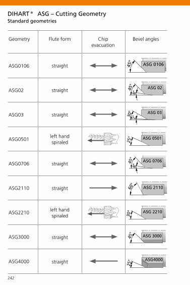
242
ASG0106 ��������
ASG02 ������
ASG03 ������
ASG0501 ��������
ASG0706��������
ASG2110
ASG2210
ASG3000 ��������
ASG4000 �������
���
��������
��������
DIHART® ASG – Cutting Geometry
Geometry Flute form Chip evacuation
Bevel angles
straight
straight
straight
left hand spiraled
straight
straight
left hand spiraled
straight
straight
Standard geometries

243
ASG07 ������
ASG0703��������
�������
ASG0704��������
��������
ASG09 ������
���
ASG09B �������
ASG1402 ��������
DIHART® ASG – Cutting Geometry
Geometry Flute formChip
evacuationcomment
Bevel angles
will be replaced by the ASG3000
straight
straight face cutting
straightface cutting,for increased
positional accuracy
will be replaced by the ASG4000
straight
straightchip breaking< x 32 mm
straightchip breaking> x 32 mm
Special geometries

244244
DIHART® ASG – Cutting GeometryThe cutting geometry (ASG) comprises:
Radial land
Rear clearance face
Primary clearance face
Secondary clearance face
Secondary cutting edge
Main cutting edge
Cutting face
• Bevel angle• Width of circular land• Backtaper• Chip angle• Primary and secondary clearance face

245
HM
DS
TT
iND
BC
DB
FD
BG
-ND
BG
-UD
JCD
JF
DIHART® Cutting Materials and CoatingsAdditional high-tech coatings are available for special applications
Cut
ting
mat
eria
ls
HM is a fine-grained carbide, which features high abrasion resistance and achieves good results in standard materials. It is very suitable for coating, and therefore mainly used also as cutting material for coated reamers.
DST is a high-performance cutting material, and very suitable for high-speed reaming. DST is ideal for machining non-alloyed or low alloyed steels up to 1200 N/mm² tensile strength. DST is also excellent for reaming nodular iron.
Coa
tings
TiN is an all purpose coating material. It has a very smooth surface and has very little affinity to many materials. This avoids structure deformation which gives excellent surface-finish results when reaming, and with considerably higher cutting data than with non coated carbide reamers.
DBC is a coating with a very high level of hardness and an extremely smooth surface. It is suitable for machining aluminium and copper alloys.
DBF is a coating that exhibits a very high level of hardness and a high resistance to oxidation. This makes the coating suitable for cast iron machining. A very smooth layer means that stainless materials can also be successfully machined.
DBG-N is a coating which offers a very high grade of hardness. The coating also has a very high oxidation resistance. This makes this particular high-performance coating very suitable for high cutting speeds, and also for using with mist coolant machining.
DBG-U: The high hot hardness and thermal cycling resistance of this TiAlN coating enable its universal use for moderate and high cutting data.
DJC is a combination of the high-performance cutting material DST and the high-performance coating DBG-N. With this combination a very high tool life with extremely high cutting data can be reached.
DJF is an AlCrN-coated cermet that is particularly well suited for using in spheroidal iron workpieces.

246
Types of tool wearDIHART® Technical Application Hints
Flank wearReduce cutting speed or use a cutting material or coating with higher abrasion resistance.
Major breakageReduce feed rate and stock allowance. Use carbide with coating instead of DST for interrupted bores.
Pitting of chip surfaceReduce cutting speed or use a more positive rake angle.
Edge wearIncrease cutting speed or use a more positive rake angle.
Notch wearReduce cutting speed or use a cutting material or coating with higher abrasion resistance.
Fatigue wear Reduce feed rate, increase stability of the reamer.
Built-up on chip surfaceUse positive cutting geometry, increase oil content of coolant, reduce cutting speed vc for uncoated carbide cutting material, increase for DST and coated cutting material.
Hairline cracks Use enough coolant and inner coolant supply, reduce cutting speed.

247
Notch wear Notch wear
Built-up
Flank wear Flank wear
Built-up
Types of tool wearDIHART® Technical Application Hints

248
DIHART®Problems possible causes solutions
Bore too large• Concentricity error of the reamer in the spindle Use
DAH® compensating holder and correct concentricity• Alignment not precise, reamer cuts at the back end
Correct alignment and use DPS floating holder• Built-up edge reduce cutting speed vc for uncoated car-
bide cutting material, increase for DST and coated cutting material or increase the oil content of the coolant
• Reamer too big have the reamer reworked
Bore too small• Worn reamer have the reamer readjusted, replaced or
repaired• Reaming allowance too small Increase reaming allowance• Cutting forces too big reduce feed or choose a different
cutting geometry (ASG)• Reamer too small have reamer readjusted, replaced or
repaired
Conical bore, tapered• Faulty alignment Correct alignment and use DPS floating
holder• Misalignment of head-stock in relation to turret correct
turret and use DPS floating holder
Conical bore, lipped• Faulty alignment. Cutting edges press at start Correct
alignment and use DPS floating holder
Bore not true• Concentricity error of reamer too large correct concentricity
using DAH® compensation system • Faulty alignment Correct alignment and use DPS floating
holder• Asymmetrical cutting through uneven entry surface
Countersink bore• Deformation through clamping of the work piece Correct
clamping of the work piece• Poor premachining optimise premachining• Feed too high reduce feed

249
DIHART®
Bore shows chatter marks• Cutting speed too high reduce cutting speed• L to D ratio too large reduce the entry speed, pilot the
bore or choose a different cutting geometry (ASG)
Surface quality unsatisfactory• Cutting edge build-up reduce cutting speed vc for un-
coated carbide cutting material, increase for DST and coated cutting material or increase oil content of the coolant
• Cutters worn have cutters repaired or replace tool• Concentricity error of reamer correct concentricity using
DAH® compensation system • Failing or insufficient coolant, chips getting jammed use
internal coolant supply and increase coolant pressure• Unsuitable coolant increase the oil content of the coolant• Wrong cutting data use data according to catalogue
recommendation
Scoring in bore «feed marks»• Cutters defective (outbreaks) replace reamer or have
repaired• Cutting edge build-ups reduce cutting speed vc for
uncoated carbide cutting material, and increase for DST and coated cutting material or increase oil content of the coolant
Scoring in bore «retraction marks»• Reamer is allowed to travel too far out of the bore Only
allow the reamer to travel out of the bore 2 mm more than the cutting length at the most
• Material springs back retraction not at a high speed, but with increased (2-3 times) feed speed
Problems possible causes solutions

250
180
º
Unequal angular position!Only two cutting edges are 180° in opposite line. Measuring teethBecause the tools are tapered measurement has to be done at the front of the cutting edge.
PCD tipped reamers require non-contact measuring device!
DIHART® Measuring

251
Mark of measuring teeth• Drive pin, lobe• Number• Punch-mark
DIHART® Measuring

TOOLS PLUS IDEAS – a PLUS for our customers and the environment
The company targetsThe KOMET GROUP pursues a consistent policy of investments and achieves long-term and profitable growth via continuous improvement of products and processes as well as via consistent qualification of employees. This increases the value of the company. The KOMET GROUP consistently increases its innovation quota via research and development, offering the market new products every year. The KOMET GROUP is a premium quality manufacturer and motivates employee qualification and customers in their IDEAS FACTORY. The training quota of vocational beginners is exemplary for the entire field of business.
The products and servicesKOMET GROUP products and services offer the customer incomparable added value. The KOMET GROUP develops, manufactures and sells the most comprehensive, modular portfolio on bore machining as full-range suppliers. The KOMET GROUP offers the most innovative technologies, thereby taking the highest economic viability, best quality and most attractive designs into account. The KOMET GROUP sees itself not purely as a tool manufacturer, but rather as suppliers of innovative solutions and ideas for the benefit of the customer: TOOLS AND IDEAS.
The customerThe KOMET GROUP places value on long-term, binding customer relations, seeing itself as a partner of the customer in a balance of benefit supplies and benefit harvests. The KOMET GROUP records customers' demands and then produces the most effective ideas and tool solutions for their machining tasks. The KOMET GROUP offers the customer information and collaboration via their worldwide presence in local Service Centres. The IDEAS FACTORY supports vocation-related training and further qualifications for customers.

The environment / surroundingsThe KOMET GROUP feels itself obliged to avoid any wastage, and therefore commits itself to responsible usage of raw materials and careful utilisation of remaining materials.The KOMET GROUP management is well aware of its responsibilities towards society, and creates the foundations for modern working environments and working conditions. The specifications on ergonomics and work safety are taken into account. Beholden to the founder, Robert Breuning, the KOMET GROUP supports the site at Besigheim, maintaining direct contact to schools and social facilities in the region.
With these claims in mind, the KOMET GROUP has introduced a modern, integrated management system, known as KMS (KOMET Management System), which is certified in accordance with ISO 9001:2008, ISO 14001:2009 and the German „Akkreditierungs-und Zulassungsverordnung Arbeitsförderung – AZAV“.
Certificationhttp://www.kometgroup.com/navigation-top/download/service/zertifikate.html
CertifiedM
anagement System

P
1.0
2.0
2.1
3.0
4.0
4.1
S
5.0
5.1
M
6.0
6.1
7.0
K
8.0
8.1
9.0
9.1
10.0
10.1
10.2
N
12.0
12.1
13.0
13.1
14.0
H
15.0
16.0
P
1.1
1.2
1.3
1.4
1.5
1.6
H
1.7
1.8
M
2.1
2.2
2.3
K
3.1
3.2
3.3
3.4
3.5
3.6
3.7
S
4.1
4.2
4.3
5.1
5.2
5.3
N
6.1
6.2
6.3
6.4
7.1
7.2
7.3
7.4
7.5
8.1
8.2
8.3
# 500
500-900
< 500
> 900
> 900
250
400
# 600
< 900
> 900
180
250
# 600 130
230
> 600 250
200
300
90
100
60
75
100
1400
1800
# 400 # 120
# 700 # 200
# 850 # 250
# 850 # 250
> 850, # 1200 > 250, # 350
> 1200 >350
# 1400 # 400
# 2200 # 600
# 850 # 250
# 850 # 250
# 1000 # 300
# 500 # 150
> 500, # 1000 > 150, # 300
400-500 200-250
# 700 # 200
> 700, # 1000 > 200, # 300
# 700 # 200
> 700, <1000 > 200, # 300
# 700 # 200
# 900 # 270
> 900, # 1250 > 270, # 300
# 500 # 150
# 900 < 270
> 900, # 1200 > 270, # 350
# 350 # 100
# 700 # 200
# 700 # 200
# 500 # 470
# 350 # 100
# 600 # 180
# 600 # 180
# 600 < 180
# 600 # 180
Selecting the Material – Threading / MillingSelecting the Material – Drilling / Reaming / Milling NotesPatentes
Mat
eria
l gro
up
Stre
ngth
Rm
(N/m
m²)
Har
dnes
s H
B
MaterialMaterial example material code/DIN
non-alloy steels St37-2/1.0037; 9SMn28/1.0715; St44-2/1.0044
non-alloy / low alloy steels St52-2/1.0050; C55/1.0525; 16MnCr5/1.7131
lead alloys 9SMnPb28/1.0718
non alloy / low alloy steels: heat resistant structural, heat treat ed, nitride and tools steels 42CrMo4/1.7225; CK60/1.1221
high alloy steels X6CrMo4/1.2341; X165CrMoV12/1.2601
HSS
special alloys Inconel 718/2.4668; Nimonic 80A/2.4631
titanium, titanium alloys TiAl5Sn2/3.7114
stainless steels X2CrNi189/1.4306; X5CrNiMo1810/1.4401
stainless steels X8CrNb17/1.4511; X10CrNiMoTi1810/1.4571
stainless / fireproof steels X10CrAl7/1.4713; X8CrS-38-18/1.4862
gray cast iron GG-25/0.6025; GG-35/0.6035
alloy gray cast iron GG-NiCr202/0.6660
spheroidal graphite cast iron (ferritic) GGG-40/0.7040
spheroidal graphite cast iron (ferritic/perlitic)GGG-50/0.7050; GGG-55/0.7055; GTW-55/0.8055spheroidal graphite cast iron (perlitic), malleable iron GGG-60/0.7060; GTS-65/0.8165
alloyed spheroidal graphite cast iron GGG-NiCr20-2/0.7661
vermicular cast iron GGV Ti<0,2; GGV Ti>0,2
copper alloy, brass, lead-alloy bronze, lead bronze (good cut) CuZn36Pb3/2.1182; G-CuPb15Sn/2.1182copper alloy, brass, bronze (average cut) CuZn40Al1/2.0550; E-Cu57/2.0060
wrought aluminium alloys AlMg1/3.3315; AlMnCu/3.0517
cast aluminium alloy (Si-content <10%), magnesium alloyG-AlMg5/3.3561; G-AlSi9Mg/3.2373
cast aluminium alloy (Si-content >10%) G-AlSi10Mg/3.2381
hardened steels (< 45 HRC)
hardened steels (> 45 HRC)
Important: For more application details and safety notes see E 86-87!
Mat
eria
l gro
up
Stre
ngth
Rm
(N/m
m²)
Har
dnes
s H
B
Material
magnetic soft iron
structural, case hardened steel
carbon steel
alloy steel
alloy / heat treated steel
alloy / heat treated steel
hardened steel to 45 HRC
hardened steel to 58 HRC
stainless steel, sulphuretted
stainless steel, austentic
stainless steel, ferritic, ferritic & austentic, martensitic
grey cast iron
grey cast iron, heat treated
vermicular cast iron
spheroidal graphite cast iron
spheroidal graphite cast iron, heat treated
malleable iron
malleable iron, heat treated
pure titanium
titanium alloys
titanium alloys
pure nickel
nickel alloys, heat resistant
nickel alloys, high heat resistant
non-alloy copper
short chip, brass, bronze, red brass
long chip brass
Cu-Al-Fe-alloy (Ampco)
Al, Mg, non-alloy
Al wrought alloy, breaking strain (A5) < 14%
Al wrought alloy, breaking strain (A5) $ 14%
Al cast alloy, Si < 10%
Al cast alloy, Si $ 10%
Thermoplastics
Thermosetting plastics
Fibre reinforced plasticsImportant: For more application details and safety notes see E 86-87!
ABS® Patent applied for inside and outside Germany
KUB K2® Patented design
KUB Quatron® Patent applications
KUB Pentron® Patent applications
KUB Trigon® EP 883 455 and other patents
KUB Duon®EP 1 296 793 and other patents and patent applications
KUB Centron® EP 0 586 423 and other patent applications
KUB® V464 EP 0 586 423 and other patents
MicroKom BluFlex® Patent applied for inside and outside Germany
UniTurn®EP 0 973 625 and other patents and patent applications
DAH Zero® Patent applications
Reamax® Patent applied for inside and outside Germany
Duomax Patent applications
MicroSet Patent applications

P
1.0
2.0
2.1
3.0
4.0
4.1
S
5.0
5.1
M
6.0
6.1
7.0
K
8.0
8.1
9.0
9.1
10.0
10.1
10.2
N
12.0
12.1
13.0
13.1
14.0
H
15.0
16.0
P
1.1
1.2
1.3
1.4
1.5
1.6
H
1.7
1.8
M
2.1
2.2
2.3
K
3.1
3.2
3.3
3.4
3.5
3.6
3.7
S
4.1
4.2
4.3
5.1
5.2
5.3N
6.1
6.2
6.3
6.4
7.1
7.2
7.3
7.4
7.5
8.1
8.2
8.3
# 500
500-900
< 500
> 900
> 900
250
400
# 600
< 900
> 900
180
250
# 600 130
230
> 600 250
200
300
90
100
60
75
100
1400
1800
# 400 # 120
# 700 # 200
# 850 # 250
# 850 # 250
> 850, # 1200 > 250, # 350
> 1200 >350
# 1400 # 400
# 2200 # 600
# 850 # 250
# 850 # 250
# 1000 # 300
# 500 # 150
> 500, # 1000 > 150, # 300
400-500 200-250
# 700 # 200
> 700, # 1000 > 200, # 300
# 700 # 200
> 700, <1000 > 200, # 300
# 700 # 200
# 900 # 270
> 900, # 1250 > 270, # 300
# 500 # 150
# 900 < 270
> 900, # 1200 > 270, # 350
# 350 # 100
# 700 # 200
# 700 # 200
# 500 # 470
# 350 # 100
# 600 # 180
# 600 # 180
# 600 < 180
# 600 # 180
Selecting the Material – Threading / MillingSelecting the Material – Drilling / Reaming / Milling NotesPatentes
Mat
eria
l gro
up
Stre
ngth
Rm
(N/m
m²)
Har
dnes
s H
B
MaterialMaterial example material code/DIN
non-alloy steels St37-2/1.0037; 9SMn28/1.0715; St44-2/1.0044
non-alloy / low alloy steels St52-2/1.0050; C55/1.0525; 16MnCr5/1.7131
lead alloys 9SMnPb28/1.0718
non alloy / low alloy steels: heat resistant structural, heat treat ed, nitride and tools steels 42CrMo4/1.7225; CK60/1.1221
high alloy steels X6CrMo4/1.2341; X165CrMoV12/1.2601
HSS
special alloys Inconel 718/2.4668; Nimonic 80A/2.4631
titanium, titanium alloys TiAl5Sn2/3.7114
stainless steels X2CrNi189/1.4306; X5CrNiMo1810/1.4401
stainless steels X8CrNb17/1.4511; X10CrNiMoTi1810/1.4571
stainless / fireproof steels X10CrAl7/1.4713; X8CrS-38-18/1.4862
gray cast iron GG-25/0.6025; GG-35/0.6035
alloy gray cast iron GG-NiCr202/0.6660
spheroidal graphite cast iron (ferritic) GGG-40/0.7040
spheroidal graphite cast iron (ferritic/perlitic)GGG-50/0.7050; GGG-55/0.7055; GTW-55/0.8055spheroidal graphite cast iron (perlitic), malleable iron GGG-60/0.7060; GTS-65/0.8165
alloyed spheroidal graphite cast iron GGG-NiCr20-2/0.7661
vermicular cast iron GGV Ti<0,2; GGV Ti>0,2
copper alloy, brass, lead-alloy bronze, lead bronze (good cut) CuZn36Pb3/2.1182; G-CuPb15Sn/2.1182copper alloy, brass, bronze (average cut) CuZn40Al1/2.0550; E-Cu57/2.0060
wrought aluminium alloys AlMg1/3.3315; AlMnCu/3.0517
cast aluminium alloy (Si-content <10%), magnesium alloyG-AlMg5/3.3561; G-AlSi9Mg/3.2373
cast aluminium alloy (Si-content >10%) G-AlSi10Mg/3.2381
hardened steels (< 45 HRC)
hardened steels (> 45 HRC)
Important: For more application details and safety notes see E 86-87!
Mat
eria
l gro
up
Stre
ngth
Rm
(N/m
m²)
Har
dnes
s H
B
Material
magnetic soft iron
structural, case hardened steel
carbon steel
alloy steel
alloy / heat treated steel
alloy / heat treated steel
hardened steel to 45 HRC
hardened steel to 58 HRC
stainless steel, sulphuretted
stainless steel, austentic
stainless steel, ferritic, ferritic & austentic, martensitic
grey cast iron
grey cast iron, heat treated
vermicular cast iron
spheroidal graphite cast iron
spheroidal graphite cast iron, heat treated
malleable iron
malleable iron, heat treated
pure titanium
titanium alloys
titanium alloys
pure nickel
nickel alloys, heat resistant
nickel alloys, high heat resistant
non-alloy copper
short chip, brass, bronze, red brass
long chip brass
Cu-Al-Fe-alloy (Ampco)
Al, Mg, non-alloy
Al wrought alloy, breaking strain (A5) < 14%
Al wrought alloy, breaking strain (A5) $ 14%
Al cast alloy, Si < 10%
Al cast alloy, Si $ 10%
Thermoplastics
Thermosetting plastics
Fibre reinforced plasticsImportant: For more application details and safety notes see E 86-87!
ABS® Patent applied for inside and outside Germany
KUB K2® Patented design
KUB Quatron® Patent applications
KUB Pentron® Patent applications
KUB Trigon® EP 883 455 and other patents
KUB Duon®EP 1 296 793 and other patents and patent applications
KUB Centron® EP 0 586 423 and other patent applications
KUB® V464 EP 0 586 423 and other patents
MicroKom BluFlex® Patent applied for inside and outside Germany
UniTurn®EP 0 973 625 and other patents and patent applications
DAH Zero® Patent applications
Reamax® Patent applied for inside and outside Germany
Duomax Patent applications
MicroSet Patent applications

KOMET Scandinavia ABBox 9177SE-200 39 MalmöTel. +46-40-49 28 40Fax +46-40-49 19 [email protected]
KOMET GROUP GmbHZeppelinstraße 374354 BesigheimTel. +49 7143 3730Fax +49 7143 [email protected]
P.Aro OyHallimestarinkatu 9FI-20780 KAARINATel. +358-(0)20 1474500Fax +358-(0)20 [email protected]
KOMET S.à.r.l.46-48 Chemin de la Bruyère69574 Dardilly CEDEXTel. +33(0)4 37 46 09 00Fax +33(0)4 78 35 36 [email protected]
KOMET (UK) Ltd.4 Hamel HouseCalico Business ParkTamworthB77 4BFTel. +44(0)1827.302518Fax +44(0)[email protected]
KOMET (UK) Ltd.4 Hamel HouseCalico Business ParkTamworthB77 4BFTel. +44(0)1827.302518Fax +44(0)[email protected]
KOMET Utensili S.R.L.Via Massimo Gorki n. 1120098 S. Giuliano Mil.Tel. +39-02-9 84 02 81Fax +39-02-9 84 49 [email protected]
NITEH d.o.o.Izidora Krsnjavog 1 B47000 HR-KarlovacTel. +385 47 60 01 41Fax +385 47 60 01 [email protected]
Roco B.V.Willem Barentszweg 165928 LM VenloTel. +31-77-3 23 14 00Fax +31-77-3 23 14 [email protected]
KOMET Scandinavia ABBox 9177SE-200 39 MalmöTel. +46-40-49 28 40Fax +46-40-49 19 [email protected]
KOMET GROUP GmbHZeppelinstraße 3D-74354 BesigheimTel. +43 512 28 35 59 32 Fax +43 512 28 35 59 [email protected]
KOMET-URPOL Sp.z.o.o. ul. Przyjaźni 47 bPL 47-225 Kędzierzyn-KoźleTel. +48(0)77.405 31 00Fax +48(0)77.405 31 [email protected]
KOMET IBERICA TOOLS S.L. Av. Corts Catalanes 9-11Planta baja, local 6B08173 Sant Cugat del VallesTel. +34-93-583.96.20Fax +34-93-583.96.12
S.C. INMAACRO S.R.L. Avram Iancu 86505600 Săcele-BraşovTel. +40 368 443 500Fax +40 368 443 [email protected]
KOMET GROUP GmbH ul. M.Salimganova 2V420107, Kazan Tel. +7 843 5704345Fax +7 843 [email protected]
KOMET Scandinavia ABBox 9177SE-200 39 MalmöTel. +46-40-49 28 40Fax +46-40-49 19 [email protected]
KOMET GROUP GmbHZeppelinstraße 374354 BesigheimTel. +49 7143 3730Fax +49 7143 [email protected]
KOMET GROUP CZ s.r.o.Na Hůrce 1041/2,160 00 Praha 6Tel. +42(0)2 35 01 00 10Fax +42(0)2 35 31 18 [email protected]
Schmidt HSC d.o.o.Kidriceva 253000 CeljeTel. +386 3 49 00 850Fax +386 3 49 00 [email protected]
KOMET IBERICA TOOLS S.L. Av. Corts Catalanes 9-11Planta baja, local 6B 08173 Sant Cugat del VallesTel. +34-93-583.96.20Fax [email protected]
KOMET GROUP CZ s.r.o.Na Hůrce 1041/2,160 00 Praha 6Tel. +420 235010010Fax +420 [email protected]
KOMET KESICI TAKIMLAR SAN VE TIC LTD STIYenikoy Mahallesi Koybasi cad. Akbas Sokak no 7 Sariyer ISTANBULTel. +90 212 346 01 34 Tel. +90 212 346 01 70Fax +90 212 346 01 [email protected]
POWER TOOLS KFT9019 GYOR, Tavirózsa u. 3/FTel. +36 96 511 011Fax +36 96 511 [email protected]
KOMET GROUP International AgenciesEurope
Denmark
Germany
Finland
France
Great Britain
Ireland
Italy
Croatia
Netherlands
Norway
Austria
Poland
Portugal
Romania
Russia
Sweden
Switzerland
Slovack Republic
Slovenia
Spain
Czech Republic
Turkey
Hungary

w w w . k o m e t g r o u p . c o m
ZAHRANCO, ENGINEERING TRADE15, Ali Amer Str. · 6th SectorNasr City · Cairo, EgyptTel. +20-2-2 75 43 46Fax +20-2-2 75 41 83Telex 2 10 57 YAZCO UN
VORTEX S.R.L.Pedro Morán 858Lomas del MiradorBuenos AiresTel. +54-(11) 46 53 01 25Fax +54-(11) 44 88 60 [email protected]
Rosler International PTY Ltd.P.O. BOX 696, 12 The NookBayswater, Vic. 3153Tel. +61-3-97 38 08 89Fax +61-3-97 38 08 87
Komet do Brasil Ltda.Rua Brasileira, 43907043-010 Guarulhos - São PauloTel. +55(0)11.2423-5502Fax +55(0)[email protected]
KOMET GROUP Precision Tools (Taicang) Co., Ltd.(Headquarter Asia Pacific)No. 5 Schaeffler RoadTaicang, Jiangsu Province, 215400Tel. +86(0)512.535757-58Fax +86(0)[email protected]
KOMET Precision Tools India Pvt. Ltd.16J, Attibele Industrial AreaBANGALORE - 562 107Tel. +91-80-2807 8000Fax +91-80-2807 [email protected]
PT Somagede Perkasa Kompleks Griya Inti SentosaJalan Griya Agung No: 3Sunter Agung - Jakarta 14350Tel. +62-21-6 41 07 30Fax +62-21-6 40 15 [email protected]
SHIVEH TOLID Co. LTD.# 270, West Dr. Fatemi Ave.Post Code : 14186TehranTel. +98 21 6 691 7 691Fax +98 21 6 691 7 [email protected]
ARNOLD TRADING Co., Ltd.P.O.B. 201806 Hamachtesh St.Ind. Area, Holon 58810Tel. +9 72-3-5 58 13 13Fax +9 72-3-5 58 13 17
KOMET GROUP KK# 180-00061-22-2 Naka-cho Musashino-shiTokyo Japan Grand Preo Musashino 203Tel. +81(0)422 50 0682Fax +81(0)422 50 [email protected]
KOMET of CANADATooling Solutions ULC250 Harry Walker Parkway NUnit 6B, Newmarket,Ontario, L3Y 7B4Tel. +1 (905) 954-0466Fax +1 (905) [email protected]
KOMET GROUP Precision ToolsKorea Co.,Ltd.#201, Lotte IT Castle-2, 550-1,Gasan-dong,Geumcheon-gu, Seoul, 153-768Tel. +82(0)2.2082.6300Fax +82(0)[email protected]
GP System (Malaysia) Sdn Bhd19-1, Jalan Kenari 7Bandar Puchong Jaya 47100 Puchong, SelangorTel. +60-3-807 59160Fax +60-3-807 [email protected]
KOMET de México S. de R. L. de C.VAcceso 1 Nave 8 No. 116 Fraccionamiento Industrial La Montaña Querétaro, Qro. C.P 76150 MéxicoTel. +52 442 2109020Fax +52 442 [email protected]
Coulson Carbide LimitedDouble J Centre, 24 Gum Road,Henderson Valley, HendersonP.O.Box 21-228, HendersonAuckland Tel. +64-9-8 38 50 61Fax +64-9-8 37 62 86
GP System (Singapore) Pte. Ltd.No. 51, Bukit Batok Crescent#04-04/05 Unity CentreSingapore 658077Tel. +65-68 61 26 63Fax +65-68 61 35 [email protected]
MULTITRADE DISTRIBUTORSP.O. Box 3511Kempton Park1620Tel. +27-11-453-8034Fax +27-11-453-9696
Hung Chih Ltd., Co.No. 37, Chung Cheng RoadTainan, Taiwan, R.O.C.Tel. +8 86-6-2 25 22 16Fax +8 86-6-2 20 59 [email protected]
PERFECT TOOL Co., Ltd.64/298Moo 3 Karnchanapisek Rd..Bakurad BagbuathongNothaburi 11110Tel. +66 2594 4562Fax +66 2594 [email protected]
KOMET of America, Inc.2050 Mitchell Blvd.SchaumburgIL 60193-4544Tel. +1 (8 47) 9 23 / 84 00 +1 (8 47) 9 23 / 84 80Fax +1 (8 00) 8 65 / 66 [email protected]
TINH HA Trading & Service Co., Ltd.Add: 12th Floor, Zodiac Building, Duy Tan Street, Dich Vong Ward,Cau Giay District, Hanoi, VietnamTel. +84 4 62851631Fax +84 4 [email protected]
KOMET GROUP GmbHZeppelinstraße 374354 BesigheimGERMANYTel. +49 7143 3730Fax +49 7143 [email protected]
KOMET GROUP GmbHRuppmannstraße 3270565 Stuttgart / VaihingenGERMANYTel. +49 711 788910Fax +49 711 [email protected]
399 01 099 00-2T-01/14 Printed in Germany www.wachter.de© 2014 KOMET GROUP GmbHWe reserve the right to make modifications.
Precision has a name
Precision and qualitiy do not allow any compromises
in universal cutting operations.
KOMET GROUP is a leading system supplier going
global for precision tools and offers individual
problem solvings and innovative top engineering.
This guarantees consistent quality and economic
efficiency.
Precision tools for drilling into the solid, boring,
fine boring, reaming, milling, turning, threading
and for special applications – this is represented
by the name of KOMET GROUP.
Ko
mG
uid
e –
Tech
nic
al M
anu
alK
om
Gu
ide
– T
ech
nic
al M
anu
al
KomGuide – Technical Manual
Drilling, Threading, Reaming, Milling
Outside Europe
Egypt
Argentina
Australia
Brazil
China
India
Indonesia
Iran
Israel
Japan
Canada
Korea
Malaysia
Mexico
New Zealand
Singapore
South Africa
Taiwan
Thailand
USA
Vietnam