kolesar 3bs 01a 0914 - lmsc, lan/man standards ...€¢ us conec has 1x16 and 2x16 mt ferrule...
TRANSCRIPT

400GBASE-SR16 Cabling
Paul Kolesar, CommScopeRobert Lingle, OFS
Alan Ugolini, USConec
IEEE P802.3bsSeptember 2014

Supporters
John Abbott, CorningMabud Choudhury, CommScopeChris Cole, FinisarMike Dudek, QLogicJack Jewell, Ind./CommScopeJonathan King, FinisarDave Lewis, JDSU
2
Dave Lewis, JDSUSharon Lutz, USConecAlan McCurdy, OFSRichard Mei, CommScopeJohn Petrilla, AvagoRick Pimpinella, PanduitRick Rabinovich, Alcatel-LucentSteve Swanson, CorningPaul Vanderlaan, Berk-Tek LLCGeorge Zimmerman, CME/CommScope

Outline
• Cabling standardization update• MDI lane assignment proposal• Compatibility with structured cabling• Rationale for choosing an MDI connector
3
• Rationale for choosing an MDI connector• Proposed content for clause xx.m.n*
* Using xx for 400GBASE-SR16 clause number

KEY
MPO-16 Standardization
• TIA TR-42 draft ANSI/TIA-604-18– First ballot completed in June 2014– Comments on second ballot to be resolved at
TR-42.13 meeting in October 2014• Second ballot advanced to national level
– Defines 16-fiber (1-row) and 32-fiber (2-row) plugs
4
– Defines 16-fiber (1-row) and 32-fiber (2-row) plugswith flat end-faces only, and adapter
– Keyed differently than MPO to prevent accidental mating attempts
• IEC 86B– New project initiated at May 2014 meeting
• 32-fiber 2-row flat end-face plug, and adapter
– Standard to become addition to IEC 61754 series
See backup slides for details

Production Status and Performance Data for 16f and 32f MPO connectors
• To meet evolving application requirements, MT fiber count has grown from single row of 4, 8, or 12 fibers to versions with 2 to 6 rows of 12-fibers– Development of 1x16 and 2x16 MTs are another progression of
technology
• US Conec has 1x16 and 2x16 MT ferrule production tooling
5
• US Conec has 1x16 and 2x16 MT ferrule production tooling• Parts have been molded for performance qualification
– Initial MM performance measurements are underway– Telcordia GR-1435 testing is scheduled

Structured Cabling Standardization
• ANSI/TIA-568.3– Defines array cabling polarity methods and components
for duplex and parallel links in structured cabling– In second ballot for D revision
(to become ANSI/TIA-568.3-D)
6
(to become ANSI/TIA-568.3-D)• Comments to be resolved at October TR-42 meeting
– Comments submitted to allow other than 12-wide array cabling
• 16-wide infrastructure would be standardized if accepted
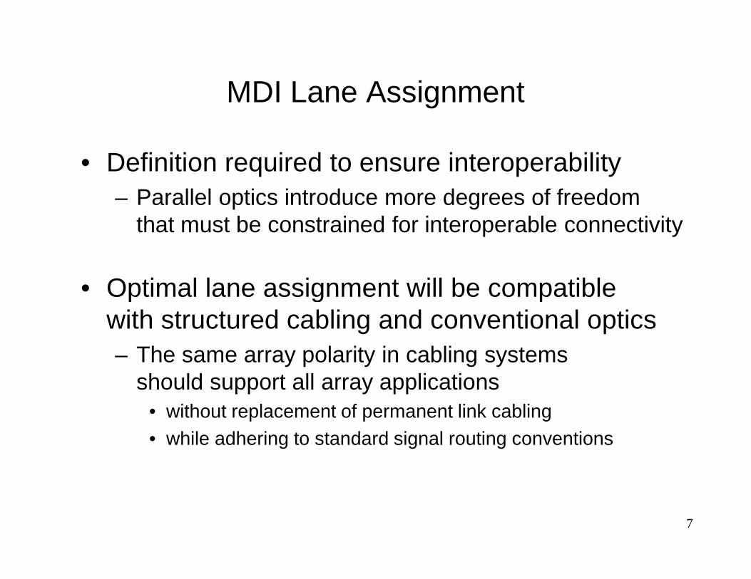
MDI Lane Assignment
• Definition required to ensure interoperability– Parallel optics introduce more degrees of freedom
that must be constrained for interoperable connectivity
• Optimal lane assignment will be compatible
7
• Optimal lane assignment will be compatible with structured cabling and conventional optics– The same array polarity in cabling systems
should support all array applications • without replacement of permanent link cabling• while adhering to standard signal routing conventions

400GBASE-SR16 Proposal for Lane Assignments
Rx Rx Rx Rx Rx Rx Rx Rx Rx Rx Rx Rx Rx Rx Rx Rx
Tx Tx Tx Tx Tx Tx Tx Tx Tx Tx Tx Tx Tx Tx Tx Tx
8
400G-SR16 optical lane assignments for MDI receptacle when viewed looking into the receptacle with keyway feature on top.
Transmitters occupy the top row and receivers occupy the bottom row.
This is essentially a 16-wide version of 100G-SR10 MDI but with transmitters on top for better heat dissipation
and no unused positions.

How Array Polarity Works• TIA-568 describes three methods: A, B, C. ISO & CENELEC one.
– All produce the same signal routing with different sets of components– Key application examples:
Supports 40G/100G-SR4
TxTx TxTx RxRxRxRx
For 1-row applications, methods deliver
cabling
9
Supports 40G/100G-SR4For 1-row applications, methods deliver lateral signal transposition (Tx to Rx)
For 2-row applications, methods deliverlateral and row transposition (Tx to Rx)
Supports 100G-SR10
RxRxRxRxRxRxRxRxRxRx
TxTx TxTxTx TxTxTx TxTx
cabling
These signal routing conventions support all standard parallel applications
including INCITS T11 10GFC 1200-Mx-SN4P-I and HIPPI-6400

-SR16 Compatibility with Cabling
• Legacy 12-fiber cabling can support 400G-SR16 consuming three cable subunits using:– fan-out modules
– tri-furcated equipment cords
32-f cord
32-f cord 3x 12-f cable
fan-out fan-out
-SR16 xcvr -SR16 xcvr
89% fiber – tri-furcated equipment cords
10
32-3x12-f cord
32-3x12-fcord 3x 12-f cable
-SR16 xcvr -SR16 xcvr
-SR16 xcvr -SR16 xcvr
32-2x16-f cord 2x 16-f cable
32-2x16-f cord
• Future 16-fiber cabling can support 400G-SR16 consuming two cable subunits using:– bi-furcated equipment cords, analogous to100G-SR10
utilization
100% fiber
utilization

Equipment Cords (Type-B)Top row: position 1
Position 12
Position 12
Position 1
Position 1
Top row: position 12
Bottom row: position 24
Bottom row: position 13
Top row: position 1Position 12
Bottom row: position 17
MPO-16 MPOs
1. Today’s standard for 2-row applicationson 12-fiber cabling
2. Example -SR16 cord
11
Position 1
Top row: position 1
Position 16
Position 16
Position 1
Top row: position 16
Bottom row: position 32
Bottom row: position 17
Position 1
Top row: position 16
Bottom row: position 32
MPO-16 MPOs2. Example -SR16 cord for 12-fiber cabling
3. Analog of today’s standard (1.)but for 16-fiber cabling
All adhere to standard of delivering lateral and row signal transposition

Connectivity Method B Supporting Parallel Signals for 1-plug x 2-row Applications
RxRx::RxRx
TxTx::TxTx
TopRow
BotRow
Transceiver
Key-up to Key-upMated Connections
Position 12
B
BPosition 1Position 12
Position 12Position 1
Position 12Position 1
Position 1
Top Row: Position 12Bottom Row: Position 24
Top Row: Position 1Bottom Row: Position 13
PU
SH
PU
LL
PU
SH
PU
LL
PU
SH
PU
LL
PU
SH
PU
LL
PU
SH
PU
LL
Proposed -SR16 MDI on modulo-16 cabling would follow this same construct.
RxRx::RxRx
TxTx::TxTx
TopRow
BotRow
Transceiver
Type-B:2-1Array Patch Cords
Type-B:1-1Array Cables
Key-up to Key-upMated Connections
Position 12
B
BPosition 1Position 12
Position 12Position 1
Position 12Position 1
Position 1
Top Row: Position 12Bottom Row: Position 24
Top Row: Position 1Bottom Row: Position 13
PU
SH
PU
LL
Example Optical Path
PU
SH
PU
LL
PU
SH
PU
LL
PU
SH
PU
LL
PU
SH
PU
LL
12

Breakout = Likely Primary App for Gen 1• The proposed -SR16 MDI can also function as
a high-density (4x) 100G-SR4 interface– Increases switch radix at 100G– Facilitates densely interconnected DC architectures at 100G– Likely to be a primary volume application
-SR4 Xcvr
Switch
4x 100G-SR4
13
-SR16 Xcvr-SR4 Xcvr
-SR4 Xcvr
-SR4 Xcvr
Switch
Switch
Switch
Switch
4x 100G-SR4
Note: 4x100G-SR4 breakout can also exist between -SR16 transceivers via structured cabling, but not via AOCs

16-fiber Cabling Applications• Modulo-16 cabling is a superior match to parallel applications
compared to modulo-12 cabling• Simpler or fewer fan-out assemblies for 100% utilization
– 32-lane solutions, bi-furcated cords
-SR16 xcvr -SR16 xcvr
32-2x16-f cord 2x 16-f cable
32-2x16-f cord
– 16-lane solutions, simple cords
– 8-lane solutions, bi-furcated cords
14
16-lane xcvr 16-lane xcvr16-f cord 16-f cable 16-f cord
16-f cable
2x8-16-f cord-SR4 xcvr
2x8-16-fcord -SR4 xcvr
-SR4 xcvr-SR4 xcvr

Why choose an array connector at the MDI?• Precedent established in clauses 86 and 95• Per proposed clause xx.m.n (see later),
behind the MDI may be a– receptacled PMD– pigtailed PMD
• Selecting MDI connector does not restrict
MDI
Undefined
PMD
PMD
15
does not restrict pigtail attachment to PMD– Open to innovation
• Choosing an MDI connector removes ambiguity– Assists in defining signal locations– Provides end-users with guidance for
• cabling installation• patch cord selection
Undefined

Content for Baseline Draft
The following 4 slides use clause 86 and 95 content as basis
with modifications for 400GBASE-SR16 and MPO-16
16

Content for Clause xx.m.n (1 of 4)xx.m.n Medium Dependent Interface (MDI)
The 400GBASE-SR16 PMD is coupled to the fiber optic cabling at the MDI. The MDI is the interface between the PMD and the “fiber optic cabling” (as shown in Figure xx-a). The 400GBASE-SR16 PMD is coupled to the fiber optic cabling through one connector plug into the MDI optical receptacle as shown in Figure xx-b. Example constructions of the MDI include the following:
17
a) PMD with a connectorized fiber pigtail plugged into an adapter;b) PMD with receptacle.

Content for Clause xx.m.n (2 of 4)xx.m.n.1 Optical lane assignmentsThe sixteen transmit and sixteen receive optical lanes of 400GBASE-SR16 shall occupy the positions depicted in Figure xx-b viewed looking into the MDI receptacle with the connector keyway feature on top. The interface contains 32 active lanes within 32 total positions. The transmit optical lanes occupy the top row. The receive optical lanes occupy the bottom row. See clause xx.m.n.2 for MDI optical connector requirements.
18
Figure xx-b -- 400GBASE-SR16 optical lane assignments viewed looking into the MDI receptacle with keyway feature on top.
Rx Rx Rx Rx Rx Rx Rx Rx Rx Rx Rx Rx Rx Rx Rx Rx
Tx Tx Tx Tx Tx Tx Tx Tx Tx Tx Tx Tx Tx Tx Tx Tx

Content for Clause xx.m.n (3 of 4)xx.m.n.2 Medium Dependent Interface (MDI) requirements
The MDI adapter or receptacle shall meet the dimensional specifications of ANSI/TIA-604-18 adapter designation FOCIS 18A-k-0. The plug terminating the optical fiber cabling shall meet the dimensional specifications of ANSI/TIA-604-18 female plug connector flat interface designation FOCIS 18P-2x16-1-0-2-2. The MDI shall optically mate with the plug on the optical fiber cabling. Figure xx-c shows an MPO-16 female plug connector with flat interface, and an MDI.
19
MPO-16 female plug connector with flat interface, and an MDI.
The MDI connection shall meet the interface performance specifications of IEC 61753-1 and IEC 61753-022-2.
NOTE— Transmitter compliance testing is performed at TP2 as defined in xx.k.j, not at the MDI.

Content for Clause xx.m.n (4 of 4)
KEY
20
Figure xx-c – MPO-16 female plug connector flat interface and MDI
MPO-16 female plug connector flat interface MDI
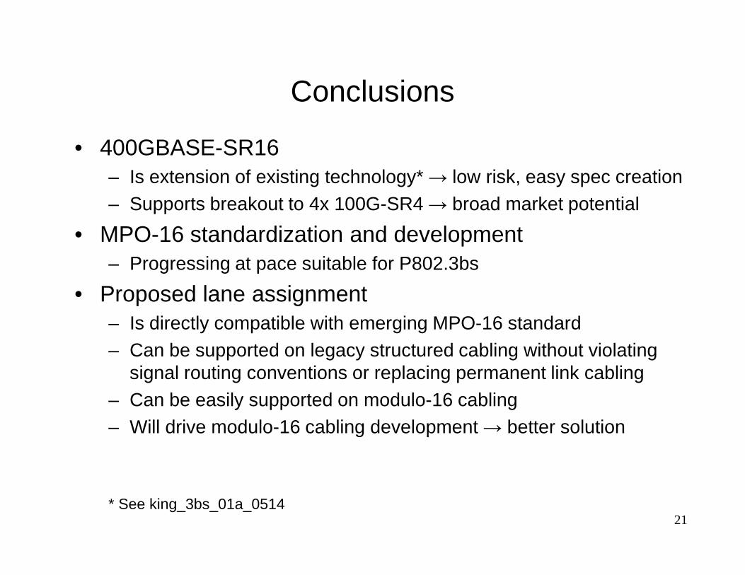
Conclusions
• 400GBASE-SR16– Is extension of existing technology* → low risk, easy spec creation– Supports breakout to 4x 100G-SR4 → broad market potential
• MPO-16 standardization and development– Progressing at pace suitable for P802.3bs
• Proposed lane assignment • Proposed lane assignment – Is directly compatible with emerging MPO-16 standard– Can be supported on legacy structured cabling without violating
signal routing conventions or replacing permanent link cabling– Can be easily supported on modulo-16 cabling– Will drive modulo-16 cabling development → better solution
21* See king_3bs_01a_0514

Thank You.
Questions?
22

Backup Slides
23

MPO-16 2-row PlugPosition Numbering Convention
OFFSET
Cut-away isometric view
24
isometric viewof plug components

MPO-16 Plug Outer Housing Dimensions
7.7 mm
25
12.6 mm
Outer dimensions aresame as MPO

Guide Pin/Hole and Fiber Hole1-row ferrule end-face
550µm
26
Conventional 250µm fiber pitch
550µm guide pin/hole

2-row ferrule end-face
Conventional 500µm row pitch
5.3mm alignment pin/hole separation
Guide Pin/Hole and Fiber Hole
27
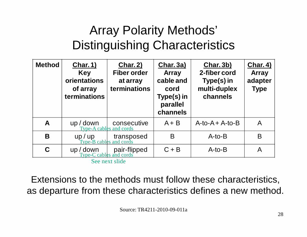
Array Polarity Methods’ Distinguishing Characteristics
Method Char. 1)Key
orientations of array
terminations
Char. 2)Fiber order
at array terminations
Char. 3a)Array
cable and cord
Type(s) in parallel
channels
Char. 3b)2-fiber cord Type(s) in
multi-duplex channels
Char. 4)Array
adapter Type
Source: TR4211-2010-09-011a28
Extensions to the methods must follow these characteristics,as departure from these characteristics defines a new method.
A up / down consecutive A + B A-to-A + A-to-B A
B up / up transposed B A-to-B B
C up / down pair-flipped C + B A-to-B A
Type-A cables and cords
Type-B cables and cords
Type-C cables and cordsSee next slide

Array Cable & Cord Types• TIA 568 defines three types (A, B, C) for 1-row and 2-row apps
Type-A
cables and 1-row cords 2-row cords (for 2-row apps)
Consecutive fiber order(key-up to key-down)
Transposed fiber order(key-up to key-up)
29
Specific concatenations of these assemblies define the three methods for parallel applications
Type-B
Type-C
(key-up to key-up)
Pair-flipped fiber order(key-up to key-down)
Adjacent pairs flipped