köln, 05 august 2005 - european aviation safety agency · 5 jaa interim policy for continued fuel...
TRANSCRIPT

EASA policy statement on the process for developing instructions for maintenance and inspection of fuel tank system ignition source prevention – 05/08/2005
Guidance on EASA Fuel Tank Safety letter Page 1
Köln, 05 August 2005 EASA D 2005/CPRO/
EASA policy statement on the process for developing instructions for m aintenance and inspection of fuel tank system ignition source prevention
Subject:
A) TC/STC Holder development and implementation of Critical Design Configuration Control Limitations resulting from Fuel Tank Safety JAA recommendation letter 2003 (end date 31 December 2005)
B) TC/STC Holder development of Fuel Tank Safety Instructions for Continued Airworthiness not related to unsafe conditions (end date 31 December 2006)
C) Guidance on Fuel Tank Safety letter JAA INT/POL/25/12 and its implementation
Dear Sir,
Part A:
Please be informed that as a consequence of JAA INT.POL 25/12 and JAA letter 04/00/02/07/03-L024 dated 3 February 2003 European TC Holders have been asked to develop and implement Critical Design Configuration Control Limitations (CDCCL’s) as part of the Fuel Tank Safety Design Reviews.
The CDCCL’s are features of the fuel system design, which must be maintained, for the complete service life of the aircraft, to ensure that any unsafe condition does not develop.
Operators will be required to develop appropriate procedures to control the CDCCL’s. The procedures shall be based on the approved information provided by the TC/STC holders. The end date for the TC/STC holders releasing the approved information is 31 December 2005. Operators would then have a further 12 months to incorporate this into their system.
Pending finalisation of EASA thinking on the regulatory framework for retro-active requirements, EASA has 2 options for the progressing with the CDCCL concept to STC/TC holders, i.e. on a voluntary basis or by mandating the CDCCL’s via EASA Airworthiness Directives. This should include all the necessary supporting maintenance instructions, practices and procedures.
In cases where a STC/TC Holder is not able or not willing to commit to adoption of the CDCCL, the Agency will mandate the development of CDCCL’s per STC/TC holder aircraft type by means of Airworthiness Directives.

2
The Agency would prefer an adoption by 31 December 2005.
I would invite you to commit on a voluntary basis to include the already or to be developed CDCCL’s into the approved Airworthiness Limitation Sections for the affected aircraft types, referenced in the Type Certificate Data Sheet (TCDS) and published in the instructions for continued airworthiness and confirm in writing to me before 1 September 2005.
If your commitment is not received, the Agency will start the process of mandating the identified CDCCL’s per manufacturer by EASA Airworthiness Directive and will co-ordinate the activity with the TC/STC holder. The EASA Airworthiness Directive(s) will be based on a TC/STC holder Service Bulletin(s) that identifies the CDCCL’s.
The AD compliance schedule with regard to the CDCCL will be such as to provide operators the same compliance period as provided by Part-M, i.e. maximum 12 months after receiving the TC/STC holder published information.
In order to meet the 31 December 2005 date mentioned in this letter, the TC/STC holder documents should be issued for approval to The Agency not later then 15 November 2005.
Part B:
TC/STC holders are – with reference to the JAA recommendation letter under Part A - also required to develop Instructions for Continued Airworthiness, i.e. the development of additional scheduled maintenance tasks not related to unsafe conditions. The attachment to this letter gives – in the absence of a formal EASA document – guidance how to develop these instructions.
The TC/STC holders are asked to commit to the development and publication of these Instructions for Continued Airworthiness as soon as possible, however not later than 31-12-2006.
TC/STC holders are asked to also confirm in writing to The Agency that this date will be met, or when deemed necessary discuss any delay with the EASA.
Part C:
Please find guidance material on the EASA Fuel Tank Safety Letter (INT/POL/25/12) and its implementation. This guidance material is derived from draft material already known by TC/STC holders as draft TGL 47. You will find some texts referring to operator responsibilities, while this letter is primarely aimed to address the issues between the EASA and the TC/STC Holders. For reasons of transparency these parts referring to operator responsibilities have not been taken out and should be seen as information for TC and STC holders.
For more information, please do not hesitate to contact Mr. H.A. Pruis from the Large Airplane Unit of the EASA Certification Division (0049 221 89990 4035) or Mr. Y Morier from the EASA rulemaking Division (0049 221 89990 5010).
Pascal Medal Yves Morier Certification Manager Large Aeroplane Head of Product Safety Certification Directorate Rulemaking Directorate

3
CC : Mr. A. Bahrami, FAA-Washington Mr. M.J. Eley, Transport Canada CTA, Brasil Mr. M. Bell, Mr. T. Heather, CAA UK Mr. H. Honert, LBA Gemany Mr. D.J. Steenbergen, IVW NL Mr. R. Jouty, DGAC France Mr. F. Jouvard, GSAC France Mr. Magnus Molitor, LFV Sweden Mr. J.M. Angulo, DGAC Spain Mr. V. De Vroey, AEA Mr. M. Eran-Tasker, AAPA EASA: Dr. N. Lohl, A. Leroy, F. Copigneaux, C. Gunitzberger, L. Gruz, H. Pruis, E. Sivel

4
Guidance on EASA Fuel Tank Safety letter
(INT/POL/25/12) and its implementation
1. INTENT
This document provides guidelines on the interpretation and implementation of JAA fuel tank safety policy, recommending a common approach for continued airworthiness of Fuel Systems. This guidance material applies to those aeroplanes identified in paragraph 4, which has applicability to Type Certificate/ Supplemental Type certificate/Major modification holders and in addition to Operators, continuing airworthiness management organisations and maintenance organisations.
2. INTRODUCTION
In recent years the aviation industry has experienced a number of incidents or accidents involving fuel tank explosions. These experiences suggest that on some aircraft types, the fuel tank system installation does not provide as high a level of protection against explosion as had been expected.
The FAA has issued a set of new rules related to fuel tank safety including SFAR 88 and appropriate amendments to parts of 14 CFR that require fuel tank system design reviews, associated modification reviews and improved maintenance procedures and practices. The JAA issued a letter dated 3rd February 2003 which requested JAA NAA to require their respective TC/STC Holders to carry out a safety review to meet JAA Interim policy on Fuel Tank Safety (INT/POL/25/12) which is harmonised with the policies of FAA, Transport Canada and CTA Brazil.
The JAA-NAA’s were requested to mandate this policy requiring holders of Type Certificates and Major Modification approvals directly related to the fuel tank system installation to undertake safety reviews based upon additional failure criteria. Where identified necessary by such safety reviews the introduction of corrective actions such as modifications, configuration critical items, improved maintenance practices and training will be introduced.
The purpose of this guidance is to notify Certificate holders, Operators and their maintenance organisations the current policy and associated actions necessary to implement the product of the above safety reviews. The Appendices to this guidance are harmonised with the FAA Policy Memorandum on Fuel Tank System Safety.
3. GENERAL

5
JAA Interim Policy for continued fuel tank safety will be implemented through EASA regulatory system regulations or JAA-NAA systems as applicable. This document interprets the interim policy by providing additional guidance in order that a harmonised approach can be achieved within the JAA community and that of the FAA (FAA memorandum ANM112-05-011, ‘Policy Statement on Process for Developing SFAR No. 88 – related Instructions for Maintenance and Inspection of Fuel Tank Systems, dated October 6, 2004), Transport Canada and CTA Brazil.
The JAA Interim Policy highlights the need for a safety review based on JAR 25.1309 practices, and taking into consideration in-service experience. The reviews are expected to be carried out by the applicable Type Certificate Holder, Supplemental Type Certificate Holder, major Modification Approval Holder or an appropriately Approved Design Organisation, which for the purposes of this document will be referred to as the Certificate Holder. Where such reviews have identified unsafe conditions, action to correct these will be mandated using EASA regulatory system regulations or JAA-NAA systems as applicable.
Where the safety review has not identified an unsafe condition but identifies a non-compliance with JAA interim policy, then the Certificate Holder is to establish the need for revisions to relevant instructions for continued airworthiness, including maintenance requirements and improved maintenance practices required to maintain a satisfactory level of safety: guidance is to be found in Appendix B. Certificate Holders, Operators and their maintenance organisations will need to comply with the contents of this document as appropriate.
4 APPLICABILITY
In line with the JAA Interim Policy, the EASA letter applies to all turbine powered Large Transport Aeroplanes certificated after 1 January 1958 with a Type Certificated passenger capacity of 30 seats or more, or a payload of 3402 kg or more.
5 REQUIREMENT
Fuel Tank Safety interim policy requires holders of certificates directly related to the fuel system installation on applicable aeroplanes to carry out a safety assessment in accordance with the principles of JAR 25.1309, using the guidance material provided in Appendix A to this document. It must be shown that an ignition source within the fuel system cannot result from a single failure and is extremely improbable. For the purpose of this analysis, the whole fuel system should be assumed to be in the flammable range. In addition it should be shown that no heat transfer can lead to fuel auto-ignition within the fuel system. All systems, including the fuel system, which can release heat, in normal and failure conditions to the fuel system should be considered.
Although the assumption is that the fuel tank will always be considered to be flammable, it is recognised that not all non-compliances with JAR 25.1309 necessarily result in an unsafe condition. Harmonised criteria have been developed to determine those non-compliances, which result in a potential unsafe condition that requires Mandatory corrective action. These criteria, including assessment of the fuel tank flammability, are defined in Appendix A to this document.
Operators are required to identify and list all aircraft fuel tank system major modifications installed on their aircraft, advising the applicable Certificate Holder in order that they may carry out the above safety review. In cases where the Certificate Holder is unable or unwilling to carry out the safety review then

6
the Operator must engage the services of an appropriately approved design organisation to carry out such safety reviews.
The outcome of these review exercises has identified unsafe conditions and non-compliance items. Certificate holders are required to identify the means to address unsafe conditions (e.g. modifications and critical configuration features), which will all be mandated by Airworthiness Directives. Additionally, instructions for continued airworthiness are expected to be revised to address non-compliance items (e.g. new or revised Service Information, revised inspection standards, and amendment of Maintenance Manuals including the revision of Standard Practices). The changes to the instructions for continued airworthiness will be developed by using conventional methodology and processes.
In order to implement the product of these safety reviews Operators, continuing airworthiness management organisations and maintenance organisations will be expected to provide appropriate training for maintenance personnel, amend maintenance procedures, and make amendments to Approved Maintenance Programmes as necessary.
6 COMPLIANCE
Safety reviews have identified unsafe conditions and corrective actions, which are being mandated by Airworthiness Directives in the normal way including the compliance criteria. Non-compliances with the Interim policy, which do not present an unsafe condition, have been identified and instructions for continued airworthiness will be amended by the Certificate holders to address these non compliances.
Note: In accordance with Part M.A.302: operators will be required to take into account the above into their approved maintenance programmes and maintenance organisations are expected to implement these amendments by introducing training and amending their own procedures and maintenance programmes within 12 months of receipt of the updates:
• as necessary by 31.12.2006 for ignition prevention related actions • 31.12.2007 for all other instructions for continued airworthiness
Guidance on EASA Fuel Tank Safety letter Page 1
Appendix A to “Guidance on EASA Fuel Tank Safety le tter”
(INT/POL/25/12) and its implementation
1 INTRODUCTION
Service history has shown that ignition sources have developed in aircraft fuel tanks due to unforeseen failure modes or factors that may not have been considered at the time of original certification of the aircraft. The purpose of this material is to provide guidance in order to show compliance with INT/POL/25/12 published by JAA on 1st of October 2000.
Each applicant should review aircraft service records, flight logs, inspection records, and component supplier service records to assist in establishing any unforeseen failures, wear or other conditions that could result in an ignition source within the fuel system. In addition, in some cases changes to components may have been introduced following certification without consideration of possible effects of the changes to the requirements to preclude ignition sources. Therefore, results of reviewing this service history information and a review of changes to components from the original type design should be `documented as part of the fuel tank system design review and safety analysis.
2 BACKGROUND
There are three primary phenomena that can result in ignition of fuel vapours in aeroplane fuel
tanks. The first is electrical arcs. The second is friction sparks resulting from mechanical contact of rotating equipment in the fuel tank. The third is hot surface ignition or auto ignition.
The conditions required to ignite fuel vapours from these ignition sources vary with pressures and temperatures within the fuel tank and can be affected by sloshing or spraying of fuel in the tank. Due to the difficulty in predicting fuel tank flammability and eliminating flammable vapours from the fuel tank, design practices have assumed that a flammable fuel air mixture exists in aircraft fuel tanks and require that no ignition sources be present.
Any components located in or adjacent to a fuel tank must be qualified to meet standards that assure, during both normal and failure conditions, ignition of flammable fluid vapours will not occur. This is typically done by a combination of design standards, component testing and analysis. Testing of components to meet explosion proof requirements is carried out for various single and combinations of failures to show that arcing, sparking, auto ignition or flame propagation from the component will not occur. Testing for components has been accomplished using standards and component qualification tests. The standards include for example Eurocae / RTCA DO160 and BS 3G 100 that defines explosion proof requirements for electrical equipment and analysis of potential electrical arc and friction sparks.
Therefore the focus of this re-evaluation of the aircraft fuel system should be to identify and address potential internal and external sources of ignition in the fuel tank system, which may not previously have been considered to be unsafe.

Guidance on EASA Fuel Tank Safety letter Page 2
FUEL SYSTEM IGNITION PREVENTION
MINIMIZATIONOF ELECTRICAL
SOURCES WITHINTANKS
JAR 25.1309AMJ 25.1309
MEET SAFETYOBJECTIVESJAR 25.901(c)
Advisory MaterialACJ 25.863(a)
RequirementJAR 25.863JAR 25.981
Heat generatedin adjacent
compartments
RequirementsJAR 25.1185
JAR 25.1193(e)
External fires
Advisory materialACJ25.981(a)
RequirementJAR 25.981
Internallygenerated heateg. pump faults
HOT SURFACES
requirementJAR 25.981(a)
FUEL TANKVENT
PROTECTION
Advisory MaterialACJ 25X899
RequirementJAR 25X899
BONDING ANDSTATIC CHARGE
GENERAL
RequirementJAR 25.973(d)
BONDING ANDSTATIC CHARGE
REFUELLINGPOINTS
RequirementJAR 25.954ACJ 25.954
LIGHTNINGHIRF EMI
PROTECTION
StandardDO 160
ELECTRICALEQUIPMENT
(ExplosionProofness)
INTERNAL ARCS,SPARKS
(Intrinsic Safety)
FRICTION SPARKS
Silver sulphideHot wires
HOT FILAMENTS
NO TANK IGNITION SOURCES
INT/POL/25/12
3 IGNITION SOURCES
3.1 Electrical Arcs and Sparks
Ignition sources from electrical arcs can occur as a result of electrical component and wiring failures, direct and indirect effects of lightning, HIRF / EMI, and static discharges.
The level of electrical energy necessary to ignite fuel vapours is defined in various standards. The generally accepted value is 0.2 millijoules. An adequate margin needs to be considered, when evaluating the maximum allowable energy level for the fuel tank design.
3.2 Friction Sparks
Rubbing of metallic surfaces can create friction spark ignition sources. Typically this may result from debris contacting a fuel pump impeller or an impeller contacting the pump casing.
3.3 Hot Surface Ignition
Guidance provided in AC25-8 has defined hot surfaces, which come within 30 degrees Centigrade (50oF) of the autogenous ignition temperature of the fuel air mixture for the fluid as ignition sources. It has been accepted that this margin of 30 degrees Centigrade
supported compliance to JAR 25.981(a). Surface temperatures not exceeding 200oC have been accepted without further substantiation against current fuel types.

Guidance on EASA Fuel Tank Safety letter Page 3
4 LESSONS LEARNED
4.1 Introduction
As detailed above, the fuel system criticality may not have been addressed in the past against current understanding as far as the ignition risk is concerned. Inspections and design review have been performed, resulting in findings detailed below. One the main lessons learned is to minimize electrical sources within fuel tanks (see § 4.3).
4.2 Components in-service experience
The following sections intend to present a list of faults, which have occurred to fuel system components. By its nature it cannot be an exhaustive list, but is only attempting to provide a list of undesirable features of fuel system components that should be avoided when designing fuel tanks.
Pumps
(a) Pump inducer failures have occurred resulting in ingestion of the inducer into the pump impeller and generation of debris into the fuel tank.
(b) Pump inlet check valves have failed resulting in rubbing on pump impeller. (c) Stator windings have failed during operation of the fuel pump. Subsequent failure of a
second phase of the pump caused arcing through the fuel pump housing. (d) Thermal protective features incorporated into the windings of pumps have been
deactivated by inappropriate wrapping of the windings. (e) Cooling port tubes have been omitted during pump overhaul. (f) Extended dry running of fuel pumps in empty fuel tanks, violation of manufacturers
recommended procedures, are suspected causing in two incidents. (g) Use of steel impellers which might produce sparks if debris enters the pump. (h) Debris has been found lodged inside pumps. (I) Pump power supply connectors have corroded allowing fuel leakage and electrical
arcing. (j) Electrical connections within the pump housing have been exposed and designed
with inadequate clearance to pump cover resulting in arcing. (k) Resettable thermal switches resetting at higher trip temperature. (l) Flame arrestors falling out of their respective mounting. (m) Internal wires coming in contact with the pump rotating group, energising the rotor
and arcing at the impeller / adapter interface. (n) Poor bonding across component interfaces. (o) Insufficient ground fault current capability. (p) Poor bonding of components to structure. (q) Loads from the aeroplane fuel feed plumbing were transferred. (r) Premature failure of fuel pump thrust bearings allowing steel rotating parts to contact
the steel pump side plate.
Wiring to Pumps located in metallic conduits or adjacent to fuel tank walls.
Wear of Teflon sleeving and wiring insulation allowing arcing to conduit causing an ignition source in tank, or arcing to the tank wall.

Guidance on EASA Fuel Tank Safety letter Page 4
Fuel Pump Connectors
Electrical arcing at connections within electrical connectors has occurred due to bent pins or corrosion.
FQIS Wiring
Degradation of wire insulation (cracking) and corrosion (copper sulphate deposits) at electrical connectors, unshielded FQIS wires have been routed in wire bundles with high voltage wires.
FQIS Probes
Corrosion and copper sulphide deposits have caused reduced breakdown voltage in FQIS wiring, FQIS wiring clamping features at electrical connections on fuel probes has caused damage to wiring and reduced breakdown voltage. Contamination in the fuel tanks including: steel wool, lock wire, nuts, rivets, bolts; and mechanical impact damage, caused reduced arc path between FQIS probe walls.
Bonding Straps
Corrosion, inappropriately attached connections (loose or improperly grounded attachment points). Static bonds on fuel system plumbing connections inside the fuel tank have been found worn due to mechanical wear of the plumbing from wing movement, and corrosion.
Failed or aged seals
Seal deterioration may result in leak internal or external to fuel system, as well as fuel spraying.
4.3 Minimizing electrical components hazards within fuel tanks
One of the lessons learned listed above is the undesirable presence of electrical components within fuel tanks. Power wiring has been routed in conduits when crossing fuel tanks, however, chaffing has occurred within conduits. It is therefore suggested that such wiring should be routed outside of fuel tank to the maximum extent possible. At the equipment level, connectors and adjacent area should be taken into account during the explosion proofness qualification of the equipment (typically, pumps).
However, for some wiring, such FQIS or sensor wiring, it might be unavoidable to route them inside of tanks, and therefore they should be qualified as intrinsically safe. The Safety Assessment section below indicates how any residual fuel tank wiring may be shown to meet the required Safety Objectives.
5 SAFETY ASSESSMENT
5.1 Introduction
The fuel system must comply with JAR 25.901(c), which requires compliance to JAR 25.1309. According to INT/POL/25/12, the applicant should perform a Safety Assessment of the fuel system showing that the presence of an ignition source within the fuel system is Extremely Improbable and does not result from a single failure, as per JAR 25.1309 and the corresponding AMJ 25.1309 principles.

Guidance on EASA Fuel Tank Safety letter Page 5
Advisory Material Joint (AMJ) 25.1309, “System Design and Analysis” describes methods for completing system safety assessments (SSA). The depth and scope of an acceptable SSA depends upon the complexity and criticality of the functions performed by the system under consideration, the severity of related failure conditions, the uniqueness of the design and extent of relevant service experience, the number and complexity of the identified causal failure scenarios, and the ability to detect contributing failures. The SSA criteria, process, analysis methods, validation and documentation should be consistent with the guidance material contained in AMJ 25.1309 and attached tables 1 and 2.
Failure rates of fuel system component should be carefully established as required using in-service experience to the maximum extent.
5.2 Assumptions and Boundary Conditions for the Analysis:
The analysis should be conducted based upon assumptions described in this section.
5.2.a Fuel Tank Flammability
The system safety analysis should be prepared considering all aircraft flight and ground conditions, assuming that an explosive fuel air mixture is present in the fuel tanks at all times.
5.2.b Failure Condition Classification
Unless design features are incorporated that mitigate the hazards resulting from a fuel tank ignition event, (e.g. polyurethane foam), the SSA should assume that the presence of an ignition source is a catastrophic failure condition.
5.2.c Failure conditions
The analysis should be conducted assuming deficiencies and anomalies, failure modes identified by the review of service information on other product as far as practical, and any other failure modes identified by the fuel tank system functional hazard assessment. The effects of manufacturing variability, ageing, wear, corrosion, and likely damage should be considered.
In service and production functional tests, component acceptance tests and maintenance checks may be used to substantiate the degree to which these states must be considered. In some cases, for example component bonding or ground paths, a degraded state will not be detectable without periodic functional test of the feature. For these features, inspection/test intervals should be established based on previous service experience on equipment installed in the same environment. If previous experience on similar or identical components is not available, shorter initial inspection/test intervals should be established until design maturity can be assured.
Fuel Pumps.
Service experience shows that there have been a significant number of failure modes, which have the capability of creating an ignition source within the tank. Many of these are as the result of single failures, or single failures in combination with latent failures. Where fuel pumps can be uncovered during normal operation, modifications will be required to ensure that pumps do not become uncovered (by fuel) or that pump failures will not cause

Guidance on EASA Fuel Tank Safety letter Page 6
tank fires or explosions. For the purposes of this Fuel Tank Safety Review, this will not be applied to fuel pumps, which only become uncovered at the point of complete fuel exhaustion.
Fuel Pump Wiring.
Despite precautions to prevent fuel pump wire chafing, arc faults have occurred. For pump wire installations within the tank or adjacent to the tank wall to remain acceptable, additional means must be provided to isolate the electrical supply, in the event of arc faults. The means must be effective in preventing continued arcing to the conduit or the tank wall.
FQIS Wiring.
Although in recent times, constructors have made attempts to segregate FQIS wiring from other aircraft wiring, it is recognised that it is not possible to be confident, at the design stage, that the segregation will remain effective over the whole fleet life. Subsequent aircraft modifications in service may negate the design intentions. To counter this threat to FQIS
wiring, additional design precautions must be provided to positively prevent any unwanted stray currents entering the tank. The precautions taken must remain effective, even following anticipated future modifications.
Bonding Schemes.
Service experience has shown that the required Safety Objectives can be met with a dual, redundant bonding scheme, with appropriate level of inspection. No definitive advice can be given about the inspection period, but it is expected that the design and qualification of the bonding leads and attachments (or alternative bonding means) will be sufficiently robust, so that frequent inspections will not be needed.
5.2.d External Environment
The severity of the external environmental conditions that should be considered are those established by certification regulations and special conditions (e.g., HIRF, lightning), regardless of the associated probability. For example, the probability of lightning encounter should be assumed to be one.
5.3 Qualitative Safety Assessment
The level of analysis required to show ignition sources will not develop will depend upon the specific design features of the fuel tank system being evaluated. Detailed quantitative analysis should not be necessary if a qualitative safety assessment shows that features incorporated into the fuel tank system design protect against the development of ignition sources within the fuel tank system. For example, if all wiring entering the fuel tanks was shown to have protective features such as separation, shielding or surge suppressors, the compliance demonstration would be limited to demonstrating the effectiveness of the features and defining any long term maintenance requirements so that the protective features are not degraded.
Guidance on EASA Fuel Tank Safety letter Page 7
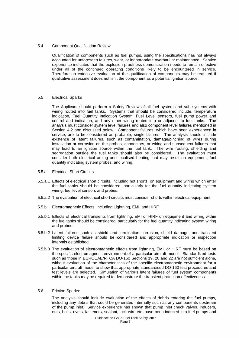
5.4 Component Qualification Review
Qualification of components such as fuel pumps, using the specifications has not always accounted for unforeseen failures, wear, or inappropriate overhaul or maintenance. Service experience indicates that the explosion proofness demonstration needs to remain effective under all of the continued operating conditions likely to be encountered in service. Therefore an extensive evaluation of the qualification of components may be required if qualitative assessment does not limit the component as a potential ignition source.
5.5 Electrical Sparks
The Applicant should perform a Safety Review of all fuel system and sub systems with wiring routed into fuel tanks. Systems that should be considered include, temperature indication, Fuel Quantity Indication System, Fuel Level sensors, fuel pump power and control and indication, and any other wiring routed into or adjacent to fuel tanks. The analysis must consider system level failures and also component level failures mentioned in Section 4.2 and discussed below. Component failures, which have been experienced in service, are to be considered as probable, single failures. The analysis should include existence of latent failures, such as contamination, damage/pinching of wires during installation or corrosion on the probes, connectors, or wiring and subsequent failures that may lead to an ignition source within the fuel tank. The wire routing, shielding and segregation outside the fuel tanks should also be considered. The evaluation must consider both electrical arcing and localised heating that may result on equipment, fuel quantity indicating system probes, and wiring.
5.5.a Electrical Short Circuits
5.5.a.1 Effects of electrical short circuits, including hot shorts, on equipment and wiring which enter the fuel tanks should be considered, particularly for the fuel quantity indicating system wiring, fuel level sensors and probes.
5.5.a.2 The evaluation of electrical short circuits must consider shorts within electrical equipment.
5.5.b Electromagnetic Effects, including Lightning, EMI, and HIRF
5.5.b.1 Effects of electrical transients from lightning, EMI or HIRF on equipment and wiring within the fuel tanks should be considered, particularly for the fuel quantity indicating system wiring and probes.
5.5.b.2 Latent failures such as shield and termination corrosion, shield damage, and transient limiting device failure should be considered and appropriate indication or inspection intervals established.
5.5.b.3 The evaluation of electromagnetic effects from lightning, EMI, or HIRF must be based on the specific electromagnetic environment of a particular aircraft model. Standardized tests such as those in EUROCAE/RTCA DO-160 Sections 19, 20 and 22 are not sufficient alone, without evaluation of the characteristics of the specific electromagnetic environment for a particular aircraft model to show that appropriate standardised DO-160 test procedures and test levels are selected. Simulation of various latent failures of fuel system components within the tanks may be required to demonstrate the transient protection effectiveness.
5.6 Friction Sparks:
The analysis should include evaluation of the effects of debris entering the fuel pumps, including any debris that could be generated internally such as any components upstream of the pump inlet. Service experience has shown that pump inlet check valves, inducers, nuts, bolts, rivets, fasteners, sealant, lock wire etc. have been induced into fuel pumps and

Guidance on EASA Fuel Tank Safety letter Page 8
contacted the impeller. This condition could result in creation of friction sparks and should be an assumed failure condition when conducting the system safety assessment.
6. INSTRUCTIONS FOR CONTINUED AIRWORTHINESS FOR THE FUEL TANK SYSTEM
The safety analysis conducted to comply with INT/POL/25/12 and this EASA letter may result in the need to define certain required inspection or maintenance items as well as changes to procedures and design changes. Any item that is required to prevent an unsafe condition by ensuring that an ignition source does not develop within the fuel tank or maintain protective features incorporated to preclude a catastrophic fuel tank ignition event must be incorporated in the limitation section of the instructions for continued airworthiness.
Information necessary to maintain those design features that have been defined in the original type design to preclude ignition sources should be included in the critical design configuration control limitations (see paragraph 7). This information is essential to ensure that maintenance, repairs or modifications do not unintentionally violate the integrity of the original fuel system type design. The original design approval holder must define a method of ensuring that this essential information will be evident to those that may perform and approve such repairs and modifications.
Further information regarding the development of scheduled maintenance and maintenance procedures will be found in the attached Appendix B.
7. DEVELOPMENT AND IMPLEMENTATION OF CRITICAL DESIGN CONFIGURATION CONTROL LIMITATIONS
Definition:
Critical Design Configuration Control Limitations (CDCCL): As applied to Fuel Tank safety policy, this term refers to a feature of the fuel system design the integrity of which must be maintained to ensure that unsafe conditions do not develop. Features in an aircraft installation or component that must be retained during modification, change, repair, or scheduled maintenance characterize CDCCL. These features may exist in the fuel system and its related installation or in systems that could, if a failure condition were to develop, interact with the fuel system in such a way that an unsafe condition would develop in the fuel system.
The definition of Critical Design Configuration Control Limitations does not include, “all the features inherent,” in a design; it includes only information necessary to ensure safety of fuel tank systems. The consideration underlying this definition is that holders of type certificates and supplemental type certificates should develop this information and make it available to operators of affected airplanes. This is consistent with the information required for airworthiness limitations required by CS25.571, “Damage-tolerance and fatigue evaluations of structure.”
The Critical Design Configuration Control Limitations will be identified in the Airworthiness Limitation section of the Instructions for Continuing Airworthiness as an Airworthiness Limitation Item. However, the Critical Design Configuration Control Limitations are not inspections or life-limited items, as are most existing Airworthiness Limitation Items. They are features usually controlled by having operators (or, where necessary, holders of type certificates or supplemental type certificates) develop appropriate procedures. Some examples of Critical Design Configuration Control Limitations (CDCCL) are the following:
a. Example 1. In some cases, the CDCCL will apply when an operator replaces a fuel tank system component that has a critical design feature. Assume that the lack of a bonding strap would disable an ignition prevention feature and, thus, contribute to an unsafe condition. A typical CDCCL item would be the means to ensure reattachment of the fuel pump bond strap when an operator changes the pump. Only the reattachment of the

Guidance on EASA Fuel Tank Safety letter Page 9
bonding strap is essential to prevent the unsafe condition. Therefore, the CDCCL is reattaching the bonding strap—not the entire installation procedure.
b. Example 2. A specific configuration of the fuel tank system may be identified as necessary to prevent development of an unsafe condition. Assume that separation of external fuel gauging system wires has been determined as a way to keep unsafe energies out of the fuel tank. Separating fuel gauging system wiring from other wiring would become a CDCCL. This step ensures that—in combination with another failure—unsafe ignition energies cannot be produced in the fuel system.
c. Example 3. In the event of certain failures, specific features of components, such as fuel pumps, ensure the mitigation of a hazardous condition. The safety concern is that, in the event of a pump repair or overhaul, certain safety features may not be installed or overhauled in accordance with the Component Maintenance Manual or other maintenance procedures acceptable to certificating authority for that component. The fuel pump will become the CDCCL and should be identified as such.
8. IDENTIFICATION AND AWARENESS OF CRITICAL DESIGN CONFIGURATION CONTROL LIMITATIONS
The holder of a type certificate or supplemental type certificate will normally identify each CDCCL as an item in the Airworthiness Limitation section of the existing Instructions for Continuing Airworthiness. This is the mechanism for identifying critical configuration features and requiring their control. To ensure that the mechanic maintaining the airplane or the operator introducing a modification is aware of the need to consider the critical configuration feature, it will be necessary to insert cross-references to CDCCLs in certain documents.
1. For CDCCLs like that in Example 1, the holder of a type certificate or supplemental type certificate should identify the task with WARNING or CAUTION notes for the critical item in the AMM procedure affected. The entity that operates or maintains the airplane should ensure that there are procedures for adequate maintenance of the CDCCLs.
2. For CDCCLs like that in Example 2, the holder of a type certificate or supplemental type certificate should include information in standard practices manuals, such as the standard wiring practices manual for the type design.
3. For CDCCLs like that in Example 3, the holder of a type certificate or supplemental type certificate should identify the appropriate Component Maintenance Manual. In addition, the certificate holder should insert a statement into both the Component Maintenance Manual and the Airplane Maintenance Manual that the component is classified as a CDCCL and, therefore, that it may be repaired or overhauled only in accordance with the Component Maintenance Manual or other maintenance procedures acceptable to the certificating authority for that component.
Guidelines relative to operators, continuing airworthiness management organisation and maintenance organisation manuals and procedures may be found in appendix B
Guidelines relative to operators, continuing airworthiness management organisation and maintenance organisation training may be found in appendix B
9. DEVELOPMENT OF AIRWORTHINESS LIMITATION ITEMS
Definition:

Guidance on EASA Fuel Tank Safety letter Page 10
Airworthiness Limitation Item (ALI): As applied to Fuel Tank system safety policy, this term means fuel system mandatory instructions that can include design changes, maintenance, inspections, or procedures determined necessary to ensure that unsafe conditions do not arise in the fuel system throughout the operational life of the airplane.
For each item identified as an Airworthiness Limitation Item, the holder of a type certificate or a supplemental type certificate needs to develop instructions for design change, inspection and maintenance or procedural change.
Examples of information to consider in developing Airworthiness Limitation Item instructions are the following:
• The location of the fuel tank system components to be maintained or inspected and any access requirements.
• Any unique procedures required, such as special, detailed inspection requirements • Specific task information, such as inspections defined by pictures or schematics. • Intervals for any repetitive tasks. • Critical Design Configuration Control Limitations—for example, wire separation or pump impeller
material specifications—that cannot be altered, except in accordance with the applicable limitation. • Methods, techniques and practices required to perform the task and criteria for passing inspections. • Any special equipment or test apparatus required.
The following documentation should also be reviewed to avoid confusion or inconsistencies with existing flight crew procedures, maintenance tasks, and the Master Minimum Equipment List.
• Current Instructions for Continued Airworthiness (if they exist) that parallel maintenance and inspection requirement instructions proposed.
• Identification of the controlling document, in other words, the Airworthiness Limitation section for the fuel tank system.
• Operator comments on requirements. • Changes to the Master Minimum Equipment List. • Changes to flight crew procedures in the Aircraft Flight Manual.

Guidance on EASA Fuel Tank Safety letter Page 11
TABLE 1
SFAR 88 UNSAFE CONDITION DETERMINATION CRITERIA
ELEMENT 4: Flammability Exposure Time
A
High Flammability Exposure
Time tanks
>7%
B
High Flammability Exposure Time
Tanks driven to Low Flammability Exposure Time tanks through inerting or
other means
C
Low Flammability
Exposure Time tanks
ELEMENT 1:
Evaluation for Single
Failures
Unsafe if: Foreseeable Single Failures Jeopardize Safe Operat ion
Required Action: All identified single failure conditions must be addressed by corrective action (i.e. AD)

Guidance on EASA Fuel Tank Safety letter Page 12
ELEMENT 2:
Evaluation for Combinations of Failures
“Compliance” Unsafe if: Any non compliance to 25.981 (a) or (b) (Amendmen t
25-102) or 25.901 using guidance in AC 25.981-1
Required Action: It is expected that any non compliance finding will be considered as unsafe conditions and address ed by
corrective actions (i.e. AD)
Unsafe it: Known Combinations of Failures Jeopardize Safe Operation
Required Action: All known combinations of failures must be addressed by corrective action (i.e. AD)
ELEMENT 3:
Evaluation for In-Service Experience
Unsafe if: In-Service failures exist that either a) dissipat e energy into tank/create ignition sources, or b) c ompromise fuel tank safety protection devices
Required Action: All of the in-service failures must be addressed by corrective action (i.e. AD)

Guidance on EASA Fuel Tank Safety letter Page 13
TABLE 2
FLAMMABILITY EXPOSURE TIME DETERMINATION
continued on next page

Guidance on EASA Fuel Tank Safety letter Page 14
STEP 1
Can the tank satisfy the Low Flammability exposure time characteristics by qualitative inspection and design review?
If Yes, tank is a Low Flammability exposure time tank, if No, go to Step 2
STEP 2
Can the tank meet the Quantitive criteria for a Low Flammability exposure time tank?
If Yes, Tank is a Low Flammability exposure time ta nk, if No, go to Step 3
Step 3
Can the tank meet the Low Flammability exposure tim e tank Criteria using the FAA Monte-Carlo analysis?
If Yes, Tank is a Low Flammability exposure time Ta nk, if No, Tank is a High Flammability exposure time ta nk
Characteristics of a Low Flammability Exposure Time Tank
Low Heat Input:
Step 1: Qualitative Inspection & Design Review:
No or very small airplane based heat sources (A fue l temp rise of less than 10 deg F above ambient on the ground, for a 100 deg F day with an 80% full fuel load) internal/external to the tank, including heat transfer from an adjacent tank that could heat the tank, and
Ability to reject heat quickly to outside air. A c onventional Aluminium skin stringer construction, high percentage (80 to 90%) of surfac es exposed to free steam air
Step 2: Quantitative Determination:
Less than 10 deg F above ambient temperature rise o n the ground over many hours with an 8-% full fuel load, and
Initial cruise cooling rates of 20 deg F per hour, with tank 80% full, and 25 deg F per hour with tank empty, starting from 60 deg F and TAT of -20 d eg F, and
End of long cruise tank temperature within 10 deg F of TAT
Step 3: Monte-Carlo Method:
Has a Fleet Average Flammability exposure time of n o greater than 7% using the FAA Monte-Carlo Model, and
A fuel temperature rise of less than 20 deg F on th e ground starting with a 100 deg F day

Guidance on EASA Fuel Tank Safety letter Page 15
Appendix B to “Guidance on EASA Fuel Tank Safety le tter”
Issue 1
July 2004
1. Development of Maintenance Instructions In Support Of Continued Airwor thiness.
The information contained in this Appendix is applicable to TC/STC Holders as well as operators, continuing airworthiness management and maintenance organisations.
This guidance material is applicable to in-service reviews as well as the initial development of maintenance instructions for new types and STC. The intention in the longer term will be to develop recommendations for revisions to the MSG analysis methodology as well as operating and maintenance rules to take account of this material.
The maintenance of ignition prevention features is necessary for the inherent safety and reliability of an airplane’s fuel tank system. The airplane cannot be operated indefinitely with the failure of an ignition prevention feature. The failure will have a direct adverse effect on operational safety. It could prevent the continued safe flight and landing of the airplane or cause serious or fatal injury to the occupants. The fuel system review required will identify ignition prevention features of the design. The failure of any of these features may not immediately result in an unsafe condition, but it may warrant certain maintenance to support continued airworthiness.
In terms of the development of maintenance instructions, the ignition prevention features of the fuel tank system should be treated the same as any other design features. In the conduct of normal operation the operating crew would not be made aware of any failure of the ignition prevention features. Normal operating procedures are those defined in the operator’s flight crew operating manual.
2. Maintenance Significant Item (MSI) Development.
The required safety review of the ignition prevention features of the fuel tank system may identify maintenance requirements which are new—in the sense that they were not specifically identified in the original maintenance analysis of that airplane. New maintenance requirements could include systems with second order failure conditions, which do not necessarily need immediate corrective action but which are needed to maintain continued airworthiness. For example, fuel system bonding can be identified as a subsystem and, as such, could be a Maintenance Significant Item. Any new maintenance requirements should be included in the maintenance development process to ensure full maintenance needs are treated in accordance with the established processes (e.g. MSG) as necessary.
The original maintenance analysis of the airplane should have considered functional failures of the fuel tank system but may not have explicitly considered the safety function e.g. spark or ignition prevention. Where necessary, that analysis should have developed maintenance instructions to prevent the failure conditions from developing. The safety review of the ignition prevention features identified additional failure conditions for the fuel tank systems hence the anticipated consequences of the failure may not have been previously identified. It will be necessary to review these new failure conditions as well as the safety functions in relation to existing installations and Maintenance Significant Items to address the need for new or modified maintenance instructions.

Guidance on EASA Fuel Tank Safety letter Page 16
After any new or identified Maintenance Significant Items have been selected, the functions, functional failure(s), failure effect(s), and failure cause(s) must be analysed.
• Function is the normal characteristic action of the item. • Functional failure is the failure of an item to perform its intended function within specified limits. • Failure effect is the result of the functional failure. • Failure cause is the reason for the functional failure.
When listing functions, functional failures, failure effects, and failure causes, it is important to include any ignition prevention functions as necessary. A detailed understanding of the fuel tank system and the lessons learned from the review is necessary to define the functional failure required by the maintenance development process. Functional statements should describe the protective ignition prevention function itself. For example, the bonding subsystem of the fuel system is to carry the electrical current generated in the event of lightning. Another example would be the wire harness subsystem of the fuel system is to prevent electrical shorts and sparks forming in and around the fuel tank in the event that wires external to the fuel tank chafe against a power wire.
The MSI review could generate a new “MSI list” and functional failure definitions for each MSI. The MSI selection process should be documented, so that proper disposition can be demonstrated in a review as necessary.
3. Maintenance Instructions Development.
The maintenance instructions identified during the safety review should be based on the application of engineering judgment and in-service experience (e.g. fuel tank cleaning procedures, clamping of wiring or transferring fuel). It should be understood that no effective maintenance instruction could be developed to reduce the likelihood of possible accumulation of combustible fluids in areas adjacent to fuel tank walls, hence those areas are classified as “flammable leakage zones”.
Standard processes for the development of maintenance programs will be applied to the list of MSIs to generate new or revised maintenance instructions for fuel system ICAs, if required. The functional failures of the ignition prevention features will be taken into consideration for each MSI when establishing maintenance instructions.
A strong emphasis for maintenance development should be the consideration of hidden functional (latent) failure safety effects, especially for those applicants not using MSG analysis. Hidden functional failure safety effects are those failures where the loss of one hidden function (whose failure is unknown to the operating crew) does not affect safety but which, combined with an additional functional failure, has an adverse effect on operational safety.
The maintenance task descriptions and interval requirements produced by this analysis may result in changes to maintenance instructions and standard practices documents developed by the holders of type certificates and supplemental type certificates. These changes should be published through revision to documents, such as the following:
• Aircraft Maintenance Manual • Component Maintenance Manual • Maintenance Planning Document • Maintenance Review Board Report Document • Job/Work/Task cards.
To minimize any potential for confusion regarding other changes in these documents for other systems than the fuel tank system, it is required that these documents qualify those changes applicable to the fuel tank system or segregate the results of the fuel tank system maintenance evaluation described in this guidance. These changes will then be incorporated into the operator’s
Guidance on EASA Fuel Tank Safety letter Page 17
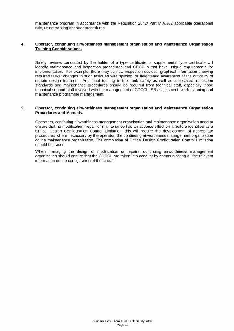
maintenance program in accordance with the Regulation 2042/ Part M.A.302 applicable operational rule, using existing operator procedures.
4. Operator, continuing airworthiness management organisation and Maintena nce Organisation Training Considerations.
Safety reviews conducted by the holder of a type certificate or supplemental type certificate will identify maintenance and inspection procedures and CDCCLs that have unique requirements for implementation. For example, there may be new inspection devices; graphical information showing required tasks; changes in such tasks as wire splicing; or heightened awareness of the criticality of certain design features. Additional training in fuel tank safety as well as associated inspection standards and maintenance procedures should be required from technical staff, especially those technical support staff involved with the management of CDCCL, SB assessment, work planning and maintenance programme management.
5. Operator, continuing airworthiness management organisation and Mainte nance Organisation Procedures and Manuals.
Operators, continuing airworthiness management organisation and maintenance organisation need to ensure that no modification, repair or maintenance has an adverse effect on a feature identified as a Critical Design Configuration Control Limitation; this will require the development of appropriate procedures where necessary by the operator, the continuing airworthiness management organisation or the maintenance organisation. The completion of Critical Design Configuration Control Limitation should be traced.
When managing the design of modification or repairs, continuing airworthiness management organisation should ensure that the CDCCL are taken into account by communicating all the relevant information on the configuration of the aircraft.

Guidance on EASA Fuel Tank Safety letter Page 18
Appendix C to “Guidance on EASA Fuel Tank Safety le tter”:
Fuel Tank Safety – SFAR 88 Implementation Process F low Chart
SFAR 88Safety
Assessment ItemsIdentification
Unsafe Condition (See Appendix B for
Process)
1.0Unsafe Condition
2.0No Unsafe Condition
2.2Post MSG ICA
Maintenance Task Development
(EZAP)
2.3Pre MSG TC/STC
Holders Recommended Maintenance Tasks (EZAP)
Yes No
2.5No Action
2.21Update MRB
Report
2.31Approved
Maintenance Program
Document
2.4Recommended
Standard Practices
3.1Introduction of fuel
system ALIs & CDCCLs into Airworthiness
Limitation Section
3.2Standard Practices
Manual
3.3Maintenance
Planning Document &
MRBR
3.4Highlight in AMM
task accomplishment
instruction
3.5Service Bulletin
1.4Airworthiness Limitation Item
(ALI)
1.41Configuration Management
(CDCCL)
1.42Maintenance
& Inspection Instructions
Examples of where the required ALI and ICA informat ion should be placed
2.1
Maintenance Instruction Development(resulting ICA required to be implemented into existing fuel system
maintenance programs per ops rules)
1.3Operational Procedures
1.2Design
Modifications
1.21Interim Actions Associated with
Design Modification (if Required)
1.1Mandatory Corrective Action
(14 CFR part 39)
Guidance on EASA Fuel Tank Safety letter Page 19
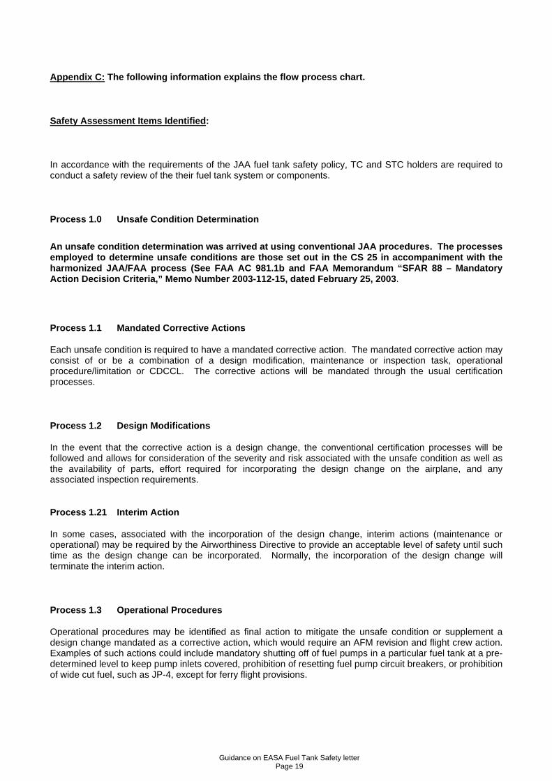
Appendix C: The following information explains the flow proces s chart.
Safety Assessment Items Identified :
In accordance with the requirements of the JAA fuel tank safety policy, TC and STC holders are required to conduct a safety review of the their fuel tank system or components.
Process 1.0 Unsafe Condition Determination
An unsafe condition determination was arrived at using conventional JAA procedures. The processes employed to determine unsafe conditions are those set out in the CS 25 in accompaniment with the harmonized JAA/FAA process (See FAA AC 981.1b and FAA Memorandum “S FAR 88 – Mandatory Action Decision Criteria,” Memo Number 2003-112-15, dated Febr uary 25, 2003 .
Process 1.1 Mandated Corrective Actions
Each unsafe condition is required to have a mandated corrective action. The mandated corrective action may consist of or be a combination of a design modification, maintenance or inspection task, operational procedure/limitation or CDCCL. The corrective actions will be mandated through the usual certification processes.
Process 1.2 Design Modifications
In the event that the corrective action is a design change, the conventional certification processes will be followed and allows for consideration of the severity and risk associated with the unsafe condition as well as the availability of parts, effort required for incorporating the design change on the airplane, and any associated inspection requirements.
Process 1.21 Interim Action
In some cases, associated with the incorporation of the design change, interim actions (maintenance or operational) may be required by the Airworthiness Directive to provide an acceptable level of safety until such time as the design change can be incorporated. Normally, the incorporation of the design change will terminate the interim action.
Process 1.3 Operational Procedures
Operational procedures may be identified as final action to mitigate the unsafe condition or supplement a design change mandated as a corrective action, which would require an AFM revision and flight crew action. Examples of such actions could include mandatory shutting off of fuel pumps in a particular fuel tank at a pre-determined level to keep pump inlets covered, prohibition of resetting fuel pump circuit breakers, or prohibition of wide cut fuel, such as JP-4, except for ferry flight provisions.

Guidance on EASA Fuel Tank Safety letter Page 20
Process 1.4 Airworthiness Limitation Items for the Fuel System
Airworthiness Limitations Items (ALI) are maintenance and inspection tasks or CDCCLs required to preclude the development of unsafe conditions within the fuel system. The maintenance and inspection tasks and CDCCLs should be properly documented within the airworthiness limitations section of the ICA and approved by the Authority.
Process 1.41 Configuration Management
Operators will be expected to demonstrate that the required control systems are in place to ensure that CDCCL items are properly identified and managed.
Process 1.42 Maintenance and Inspection Instruction s
Each limitation will describe the specific maintenance and inspection instructions, frequency and any other special requirements. It will be the responsibility of the manufacturer or operators to develop specific work instructions (e.g. job/task cards) for accomplishment of the maintenance and inspection instructions.
Process 2.0 No Unsafe Condition
All ignition prevention features identified by the safety review required by safety review, but determined not to be unsafe should be itemized and subjected to a review as described by this guidance.
Process 2.1 Maintenance Instructions Development
At the competition of the review described in this guidance, the items identified should be subjected to the standard maintenance program development methods, e.g. MSG, for developing scheduled maintenance instructions. It will be necessary to track these maintenance instructions in order to demonstrate proper disposition. These instructions will result in changes within the existing maintenance and inspection programs, as provided by the applicable operating rules.
Process 2.2 Post MSG ICA - Maintenance Task Development
These MSIs will be presented to the Maintenance Working Group (if there is a functioning MWG) and the responsible Authority where a change to the fuel tank maintenance instructions will be determined using standard maintenance processes.
Process 2.21 MRB Reports
If revision to an existing MRB Report using a current version of MSG-3 is contemplated, AGM Section 2 Chapter 16 should be followed. The deliverables from the above processes should be included within or by reference in the ICA by the TC or STC holder. In some cases the maintenance evaluation of the fuel tank system may include elements of an electrical wire interconnection system (EWIS). Where electrical elements are common to both the fuel tank system and EWIS, resulting tasks and interval should be compatible as appropriate. Because there is a plan to separately address EWIS in future operational rules, care should be taken to properly identify an EWIS consideration as opposed to fuel tank system maintenance consequence from compliance with JAA fuel tank safety policy.

Guidance on EASA Fuel Tank Safety letter Page 21
Process 2.3 Pre-MSG TC/STC Holders Recommended Sche duled Tasks
For those airplane models and modifications where the maintenance programs were developed prior to the MSG process (or without the MSG process), the TC or STC Holder should identify the MSIs (or its equivalent) by the review described in this guidance. Scheduled or unscheduled maintenance tasks and maintenance practices as suitably appropriate measures to address the MSIs identified should be developed. These instructions should be included in the Instructions for Continued Airworthiness. The scheduled maintenance instructions could be developed within the existing maintenance program.
Process 2.31 Maintenance Program Document
Recommendations by the TC or STC holder should be incorporated into the controlled maintenance program document. (e.g. maintenance planning guide) These revisions should be submitted to the appropriate authority for review.
Process 2.4 Standard Practices
The TC or STC holder may identify standard practices, which will address the MSIs identified. The practices may be associated with the original design, alteration, or maintenance. The TC or STC holder will need to ensure that the appropriate Instructions for Continued Airworthiness are revised as necessary. The operator will need to ensure that its affected documents and procedures incorporate the standard practices and that organizations responsible for alterations have access to such practices. Some examples of practices that may change are: clean tank procedures, wiring clipping practices, bonding standards, routing of power supplies to pumps and switches, wiring separation, wire splice repairs in fuel tank systems, and fuel tank and component storage procedures. These examples may also result in revision to ‘Design Standard Practices Manuals.’
Process 2.5 No Action Required
In some cases, the ignition prevention features identified by JAA fuel tank safety design review that were determined not to have a safety effect, may be determined by standard maintenance development processes, e.g. MSG, to require no action. It will be necessary to track these items and present that list to the Authority in order that a proper disposition can be demonstrated.
--- OOO ---