kocioł automatyczny 600 kw - gamma total instal · - 2 - introduction dear sirs, dear customer...
TRANSCRIPT
- 1 -
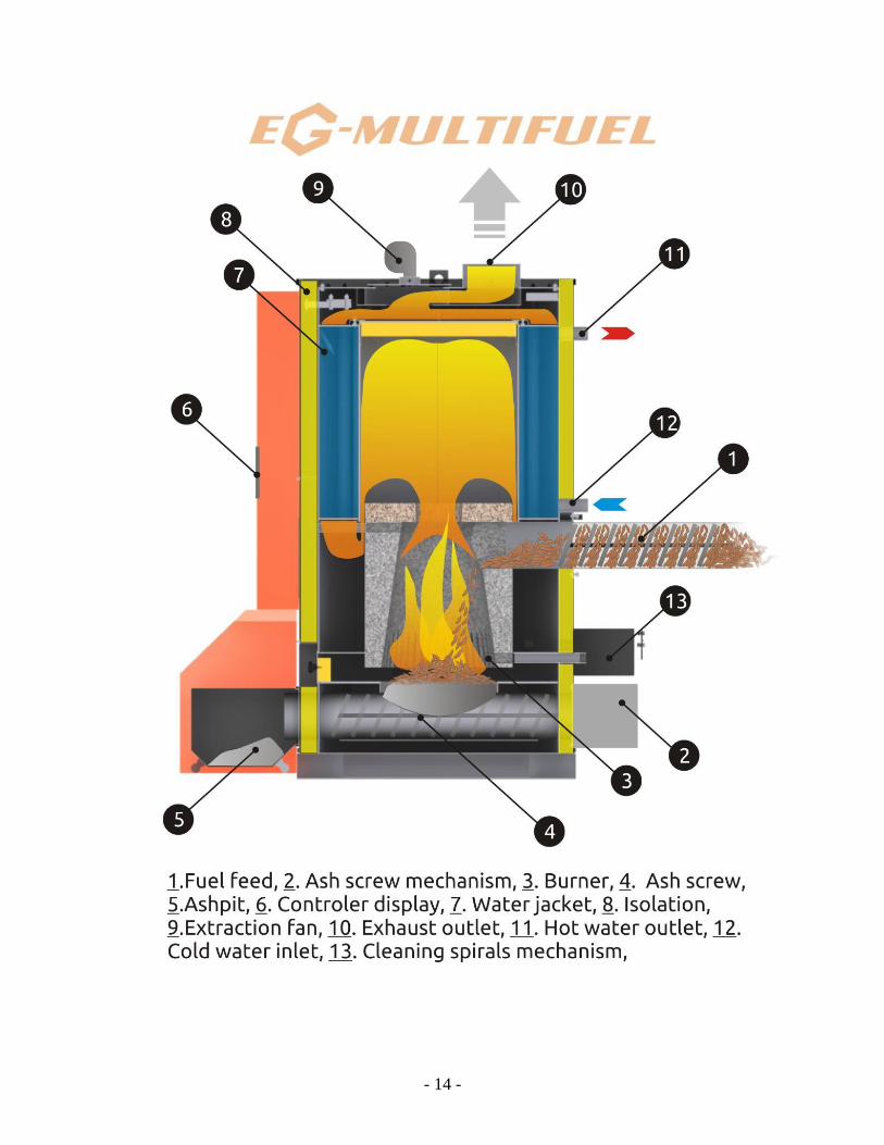
EG-MULTIFUEL Boiler
Edition 1 from 2012 ad.

- 2 -
INTRODUCTION
Dear Sirs, Dear Customer
Welcome in the circle of users of automatic boiler made by GREŃ
Company. This device is a product of long and in-depth studies. Its use and
installation require maintaining special attention, care and following the
recommendations contained in this document.
This manual has been created in a most complex way, allowing for proper
boiler installation, maintenance and use that will give full satisfaction. It is
necessary to read and understand the following instruction manual, in case of
any doubts please contact the person responsible for boiler installation or get in
touch directly with GREŃ Company.
During the installation and start-up of the boiler it is necessary to maintain
all the safety precautions, verify all essential actions and points and prevent any
damage or failure of the boiler and additional equipment, since such damage is
not covered by the warranty. Although we expect you to follow closely all the
indications included in the following instruction manual, we are pleased to
include you among our customers, hoping that you will be fully satisfied with
using the boiler. It is not advised to use too big pieces of biomass, since this
might cause premature wear on the feeding screw and motoreducers. Girth
should be less than 5cm.
7 Most important rules that must be strictly followed:
1) Fuel must be dry. Its granulometry must match the specific size provided by
manufacturer.
2) It is forbidden to make any changes in construction or settings of the boiler.
3) It is forbidden to manually interfere in the work cycle of the boiler, it may lead
to damage or ruin the feeder screw or the burner.
4) It is mandatory to strictly follow the boiler maintenance and silo filling rules.

- 3 -
5) Heat power of the biomass should not exceed 20000 kJ/kg.
6) The boiler must always be equipped with water circulation, otherwise there a
high risk of overheating, that may result in material damage or injury.
7) One should ensure that the boiler room is properly ventilated and that
exhaust and fresh air ducts are always clear and free of obstructions.
Users’ responsibility:
- Use and boiler maintenance are users’ duties and he is fully responsible for
them.
- Maladjustment to the following instructions might cause interference in boiler
operation, poor efficiency and shorter life span of the boiler.
- Boiler usage is meant for people that are physically and mentally competent to
do so.

- 4 -
Table of contents:
INTRODUCTION ................................................................................................................ 2
7 Most important rules that must be strictly followed: ............................................. 2
I) BOILER INSTALLATION ................................................................................................. 6
1) – POSITIONING OF THE BOILER: ............................................................................ 6
a) Boiler specification: ............................................................................................. 6
b) Room that the boiler is supposed to be placed in: ......................................... 6
2) – POSITIONING OF BOILER COMPONENTS: ........................................................ 7
3) POSITIONING OF THE FEEDER SYSTEM: ............................................................... 8
a) Hints on creation of the silo: ........................................................................ 8
b) Filling the silo: ..................................................................................................... 11 II) SPECIFICATION OF THE BOILER .......................................................................... 13
1) PHYSICAL SPECIFICATION .................................................................................... 13
2) SPECIFICATION OF THE HYDRAULIC SYSTEM ................................................... 15
a) Hydraulic fitting .................................................................................................. 15
3) SAFETY MEASURES AND CHIMNEY ..................................................................... 16
a) Fire protection .................................................................................................... 16
b) Protection in case of clogging ......................................................................... 16
c) Chimney ............................................................................................................... 16
4) ELECTRIC SYSTEM SPECIFICATION ...................................................................... 18
a) Main power supply ............................................................................................. 18
b) Electric connection: ........................................................................................... 18
c) Electric box: ......................................................................................................... 18
5) MOTOR SPECIFICATION ........................................................................................ 18
a) Power of included electric motors. ................................................................. 18
b) The direction of screw rotation: ...................................................................... 19
6) STB AND IGNITION ................................................................................................. 19
a) STB: ....................................................................................................................... 19
b) Automatic ignition: ............................................................................................ 20
2) STARTING ................................................................................................................ 22 3) EXTENDED PERIOD OF STOPPAGE (SUMMER SEASON)............................. 23
4) GRAIN TYPE BOILERS ............................................................................................ 24
V) BOILER MAINTENANCE............................................................................................. 25
1) ASH REMOVAL: ...................................................................................................... 25
a) removing ashes from the hearth: .................................................................... 25
b) removing the ash from exchanger: ................................................................. 25 c) removing ash from ashpit: .............................................................................. 26
2) TURBULATORS: ...................................................................................................... 27
3) ANTI-CLOGGING PROTECTION: ........................................................................... 27
4) FIRE PROTECTION: ................................................................................................. 27

- 5 -
5) SILO: ......................................................................................................................... 27
6) EXHAUST OUTLET DUCT: ...................................................................................... 30
VI) MAINTAINING THE BOILER ...................................................................................... 31
VIII) CONDITIONS OF SALES AND WARRANTY........................................................... 33
- 6 -
I) BOILER INSTALLATION
Fitters responsibility:
- Boiler installation should be done by qualified boiler fitter, with accordance
with all the rules in force.
- It is the duty of the fitter to follow all the instructions provided by the
manufacturer, as well as the instruction manual, fitting guide of the boiler and
parts, as well as to blueprints of hydraulic systems.
Fitter will be held responsible for every discrepancy in the system.
1) – POSITIONING OF THE BOILER:
a) Boiler specification:
- Nominal power: 200 kW
- Test pressure: 5 bar;
- operating pressure: 2 bar;
b) Room that the boiler is supposed to be placed in:
The boiler must be placed in a boiler room that constitutes a closed and
isolate space with air temperature above 15ºC and in compliance with current
laws and regulations. The room should be properly adapted and equipped with
proper ventilation. To facilitate the maintenance of the boiler and its parts it is
necessary to provide sufficient space around and above the boiler.
The warranty does not cover installation of the boiler and its
components in place that might cause damage or failure of
the parts (chlorine, acid, to high humidity etc.). In case of any
doubts please contact the GREŃ Company
- 7 -
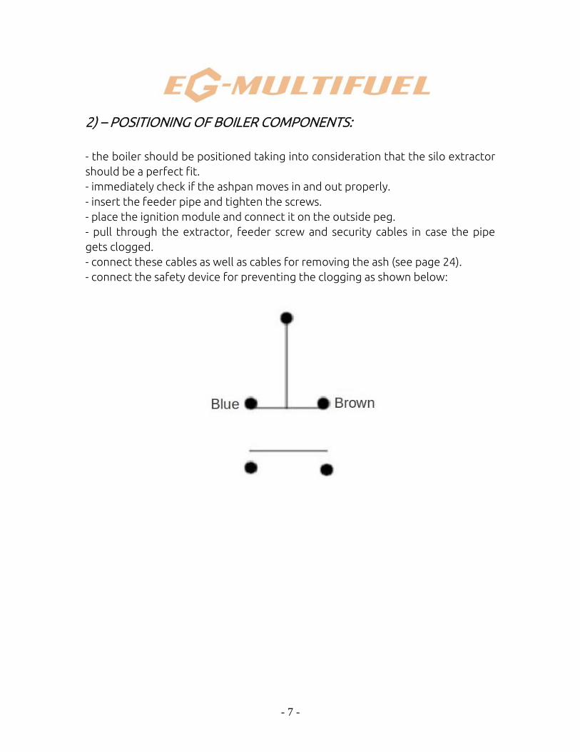
2) – POSITIONING OF BOILER COMPONENTS:
- the boiler should be positioned taking into consideration that the silo extractor
should be a perfect fit.
- immediately check if the ashpan moves in and out properly.
- insert the feeder pipe and tighten the screws.
- place the ignition module and connect it on the outside peg.
- pull through the extractor, feeder screw and security cables in case the pipe
gets clogged.
- connect these cables as well as cables for removing the ash (see page 24).
- connect the safety device for preventing the clogging as shown below:
- 8 -
3) POSITIONING OF THE FEEDER SYSTEM:
a) Hints on creation of the silo:
Ensure the easy access to the silo as well as to keep it under the maximum
size 4m x 4m x 3-5m height ( depending on the used biomass, consult with GREŃ)
for big feeder systems; 2m x 2m x 3m height for small feeder systems. For
extractors please ensure:
- a plate that will be able to hold the weight of the extractor and the biomass;
- distance from silo to the boiler should be as small as possible;
- feeder screws shouldn’t be too long otherwise this in turn will increase the load
and the use of electric power;
- organise positioning of the silo so that loading can be done freely and to ensure
that feeder screw could be easily attached and removed;
- access doors and hatches to the silo must be equipped with microswitch, that
automatically cuts of the feeding of biomass to the boiler;
Procedure for mounting the silo extractor with a bladed feeder.
- attach only the apparatus to the boiler tightening the bolts;
- to fix it to the basis drill mounting points Ø12 in diameter and place the metal
pegs provided by the manufacturer;
Mounting of blades:
Blades are mounted and preadjusted by the manufacturer;
screws cannot be tightened.
- 9 -
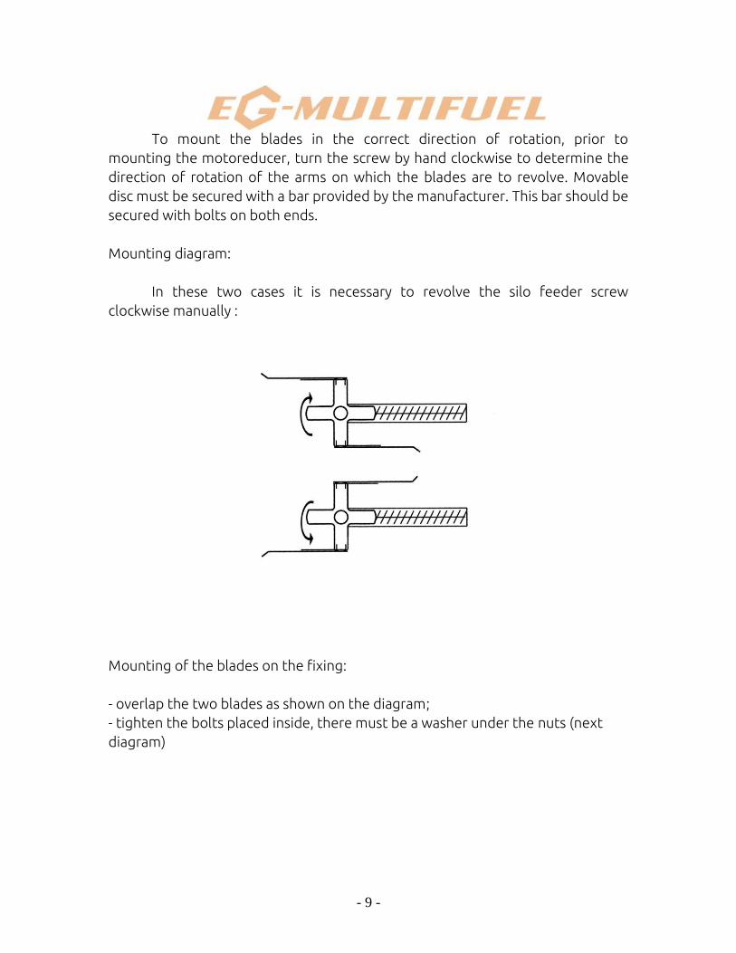
To mount the blades in the correct direction of rotation, prior to
mounting the motoreducer, turn the screw by hand clockwise to determine the
direction of rotation of the arms on which the blades are to revolve. Movable
disc must be secured with a bar provided by the manufacturer. This bar should be
secured with bolts on both ends.
Mounting diagram:
In these two cases it is necessary to revolve the silo feeder screw
clockwise manually :
Mounting of the blades on the fixing:
- overlap the two blades as shown on the diagram;
- tighten the bolts placed inside, there must be a washer under the nuts (next
diagram)
- 10 -
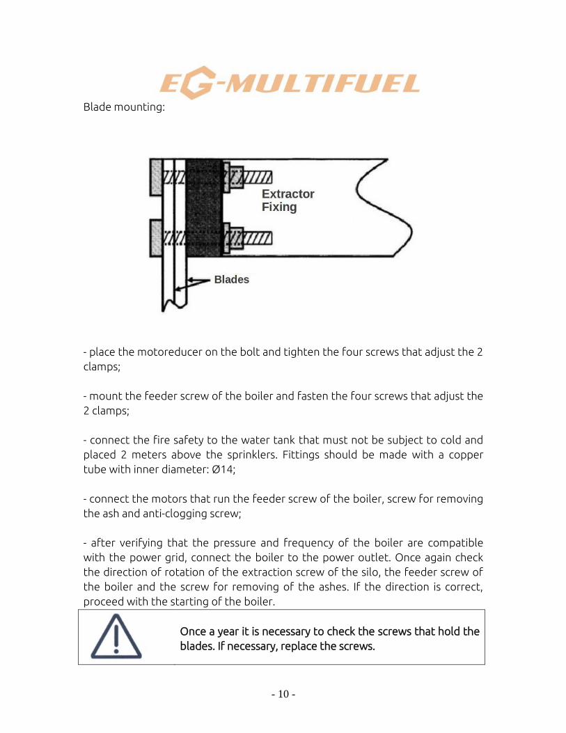
Blade mounting:
- place the motoreducer on the bolt and tighten the four screws that adjust the 2
clamps;
- mount the feeder screw of the boiler and fasten the four screws that adjust the
2 clamps;
- connect the fire safety to the water tank that must not be subject to cold and
placed 2 meters above the sprinklers. Fittings should be made with a copper
tube with inner diameter: Ø14;
- connect the motors that run the feeder screw of the boiler, screw for removing
the ash and anti-clogging screw;
- after verifying that the pressure and frequency of the boiler are compatible
with the power grid, connect the boiler to the power outlet. Once again check
the direction of rotation of the extraction screw of the silo, the feeder screw of
the boiler and the screw for removing of the ashes. If the direction is correct,
proceed with the starting of the boiler.
Once a year it is necessary to check the screws that hold the
blades. If necessary, replace the screws.
- 11 -
b) Filling the silo:
1- check if pieces of timber are not wedged between blades on a level of nuts
and bolts. In such case the remnants should be removed;
2- fill the silo to about 1m of height;
3- start the boiler so that the blades starts to revolve;
4- fill the silo completely, do not step on the biomass;
It is not advised to fill the silo with briquette that exceeds 25% humidity (per
mass, gross), since this might cause:
- emission of carbonic gas;
- heating of the silo (to the temperature of up to: 80 ˚C);
- corrosion of metal parts that the silo extractor is made of (warranty doesn’t
cover damaged parts in this case);
- risk of condensation in the silo that might result in rotting of biomass;
- incorrect boiler operation;
It is advised to fill the silo with dry briquette without dust and powder.
It is not only forbidden but also extremely dangerous to step
on the silo, since extractors generate height discrepancies
(higher and lower place up to several meters of height), that
might collapse in any moment. For security purposes all
hatches and doors to the silo must be equipped with
microswitch, that will cut the power to the boiler. Doors
must be secured with a lock, to prevent the access of
unauthorized persons.

- 12 -
Filling of the silo must be performed regularly by means of the suction feeder,
ventilator, or by the grinder, that sends the biomass to the silo, dropping the fuel
should be directed on the vertical conveyor belt, to prevent the forming of a pile
that might jam the feeder system.
To fill the silo once again it is necessary to wait until it’s almost empty, as shown
on the diagram below.
During every loading of the silo it is necessary to check if pieces of biomass are
not stuck between blades on the level of rolling bolts. In such case the pieces
must be removed. User should not allow for a situation when any object is
between the blades.
- 13 -
II) SPECIFICATION OF THE BOILER
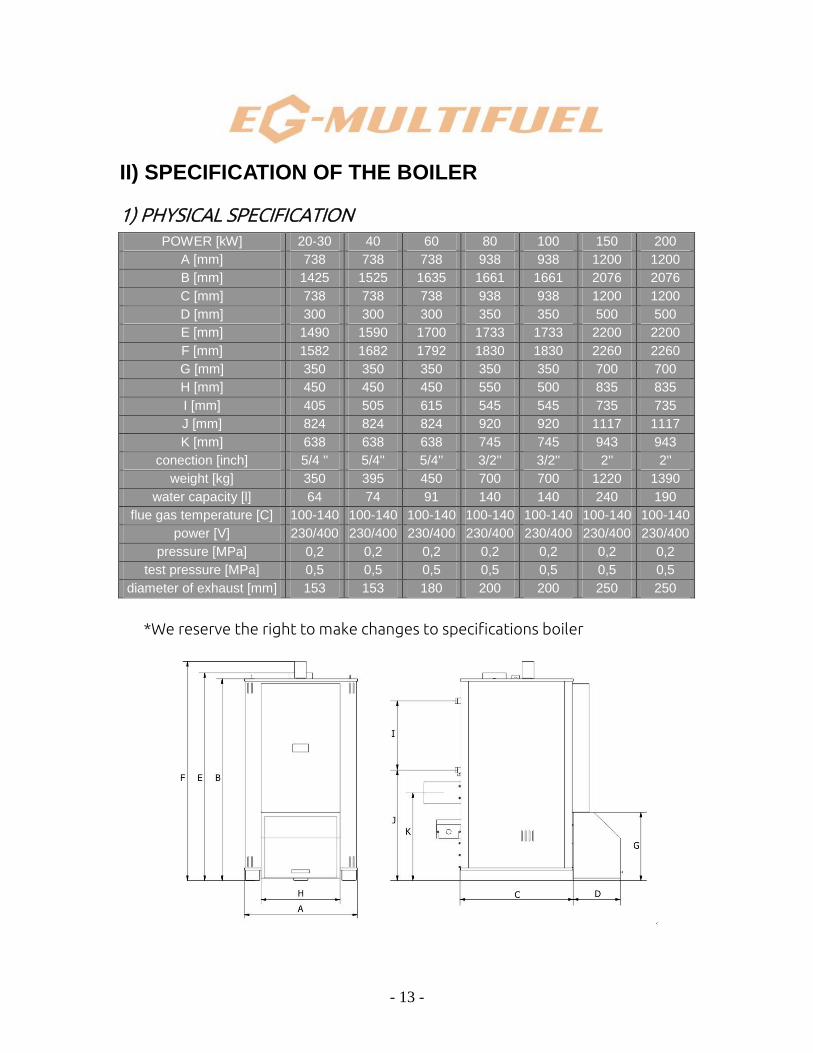
1) PHYSICAL SPECIFICATION
POWER [kW] 20-30 40 60 80 100 150 200
A [mm] 738 738 738 938 938 1200 1200
B [mm] 1425 1525 1635 1661 1661 2076 2076
C [mm] 738 738 738 938 938 1200 1200
D [mm] 300 300 300 350 350 500 500
E [mm] 1490 1590 1700 1733 1733 2200 2200
F [mm] 1582 1682 1792 1830 1830 2260 2260
G [mm] 350 350 350 350 350 700 700
H [mm] 450 450 450 550 500 835 835
I [mm] 405 505 615 545 545 735 735
J [mm] 824 824 824 920 920 1117 1117
K [mm] 638 638 638 745 745 943 943
conection [inch] 5/4 '' 5/4'' 5/4'' 3/2'' 3/2'' 2'' 2''
weight [kg] 350 395 450 700 700 1220 1390
water capacity [l] 64 74 91 140 140 240 190
flue gas temperature [C] 100-140 100-140 100-140 100-140 100-140 100-140 100-140
power [V] 230/400 230/400 230/400 230/400 230/400 230/400 230/400
pressure [MPa] 0,2 0,2 0,2 0,2 0,2 0,2 0,2
test pressure [MPa] 0,5 0,5 0,5 0,5 0,5 0,5 0,5
diameter of exhaust [mm] 153 153 180 200 200 250 250
*We reserve the right to make changes to specifications boiler
- 14 -

- 15 -
2) SPECIFICATION OF THE HYDRAULIC SYSTEM
a) Hydraulic fitting
Hydraulic fitting must be performed by qualified fitter. It consists of: thee-
channel thermostatic valve with safety set to 45˚C (made by THERMOVAR or
similar), that will be connected with water circulator, so to ensure that water
temperature is always equal or greater than 45˚C. This is meant to prevent the
corrosion of the boiler.
Manometric height of the circulator must correspond with the resistance
of the flow in the water circulation and to water use. Exceeding values of
circulator might cause opening of the thermostatic valve which in turn might
cause condensation in the heat exchanger. Heat distribution is facilitated by
three or four channel valve, via other controller or directly by heaters managed
by thermostatic valves, in case the heating system includes a differential valve or
a balloon of warm water for sanitary purposes.
Flow parameters for nominal power:
Flow for temperature difference of 10 K: 51,7 m3/s;
Flow for temperature difference of 20 K: 25,8 m3/s;
Provide a safety valve that opens at 90˚C (type 544 made by Thermador or
similar), that will ensure cooling of the boiler with cold mains water.
- Hydraulic and exhaust system must be installed so to enable easy opening of
upper boiler hatch;
- Ensure there’s enough space above the boiler to enable easy access to
turbulators;
- Hydraulic fitting of the boiler: Outlet Ø101,6; Return Ø101,6; Chute Ø42,4;

- 16 -
3) SAFETY MEASURES AND CHIMNEY
a) Fire protection
Place the fire protection tank that holds 30 liters and is positioned 2
meters above the steel 15/21 elbow that is positioned on the extraction screw of
the silo, the water in the tank should be of the ambient temperature. Under the
tank connect (CU14/16) tee allowing to be filled from EF mains with 1/4 diameter
valve. The base of the tee should be fitted into detachable joint of the steel
elbow situated on the screw. Sprinkler is on the pipe.
b) Protection in case of clogging
This protection is mounted on the pipe that covers the extraction screw of
the silo. Its purpose is to prevent from clogging. When to big chunk of wood
triggers the safety sensor, the boiler operation is interrupted. It is then necessary
to stop the automatic boiler interrupter, or shut down the boiler. Unscrew with a
correct wrench the three screws from the fixing of the sensor support in the
rube, carefully lift the safety device (the sensor is very fragile), remove the
blocking piece of wood with hand, next clean the sensor and move it slightly
around prior to mounting it again. Start the interrupter.
c) Chimney
Connection to the chimney should be done in a way that allows for its easy
detachment to gain access to the boiler. The flue must correspond to the
dimensions required for the specific model of the boiler. The diameter of the
flue must be greater at the outlet of the boiler and it must be ceramic for boilers
that run on grain-type biomass. Chimney must be equipped with an opening that
enabled cleaning of the chimney. Must comply with regulation: EN 12391-1 from
June 2004.
- chimney must have at least 5 meters of heights above the boiler;

- 17 -
- if any horizontal segment is higher than 1 meter, the height of the chimney
should be increased by the same value;
- chimney must raise above any objects that are in a vicinity by at least 70 cm, so
to prevent the suppression of fire and blowback to the silo, damage to the
igniter and possible condensation;
If the chimney height is excessively high, it is necessary to
decrease the frequency of voltage converter to 3 Hz.
Parameters:
Diameter of exhaust shaft at the boiler outlet: Ø:
o 153 mm for 20-30, 40 kW;
o 180 mm for 60 kW;
o 200 mm for 80,100 kW;
o 250 mm for 150, 200 kW;
Exhaust gas temperature:
o At the minimal power 100˚C;
o At the nominal power 150˚C;
Fuel consumption depending on the humidity of the fuel:
o For fuels with 15% humidity the approximate fuel consumption is:
150 kg/h;
o For fuels with 30% humidity the approximate fuel consumption is:
200 kg/h;
Amount of exhaust gases depending on the humidity of the fuel:
o For fuels with 15% humidity the approximate amount of exhaust
gases is: 1260 m3/h;
o For fuels with 30% humidity the approximate amount of exhaust
gases is: 1611 m3/h;

- 18 -
4) ELECTRIC SYSTEM SPECIFICATION
a) Main power supply
The mains must be equipped with a safety device, protecting the device
from voltage jumps as well from atmospheric discharge. The circuit box for the
boiler must be equipped with a residual-current circuit breaker rated at 30mA
and also with a two-pole or four-pole breaker depending on the type of
extractor. The power supply and connection to mains must comply with national
regulations (Norm EN 60335 - 1) also they must be done by a qualified specialist.
b) Electric connection:
According to the switchboard, the standard conditions of electric
connections are as follows: 230 Volt (single phase) 50 Hz or 400 Volt (three
phase +N) 50 Hz. It is necessary to check the compatibility of main electrical
system with the electrical specification of the boiler.
c) Electric box:
Access to the electric box is secured with a lock that is opened using a key,
to prevent access from unauthorised persons.
Electric box must always remain closed with a lock, that will be inaccessible to
children.
5) MOTOR SPECIFICATION
a) Power of included electric motors.
The supplied values are referring to standard system and are subject to
change depending on circumstances. Power use of the control devices are slight
(less than 20 Watt).
- 19 -
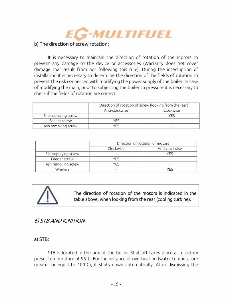
b) The direction of screw rotation:
It is necessary to maintain the direction of rotation of the motors to
prevent any damage to the device or accessories (Warranty does not cover
damage that result from not following this rule). During the interruption of
installation it is necessary to determine the direction of the fields of rotation to
prevent the risk connected with modifying the power supply of the boiler. In case
of modifying the main, prior to subjecting the boiler to pressure it is necessary to
check if the fields of rotation are correct.
Direction of rotation of screw (looking from the rear)
Anti-clockwise Clockwise
Silo supplying screw - YES
Feeder screw YES -
Ash removing screw YES -
Direction of rotation of motors
Clockwise Anti-clockwise
Silo supplying screw - YES
Feeder screw YES -
Ash removing screw YES -
Whirlers - YES
The direction of rotation of the motors is indicated in the
table above, when looking from the rear (cooling turbine).
6) STB AND IGNITION
a) STB:
STB is located in the box of the boiler. Shut off takes place at a factory
preset temperature of 95˚C. For the instance of overheating (water temperature
greater or equal to 100˚C), it shuts down automatically. After dismissing the
- 20 -
cause that triggered the shutdown it will be necessary to manually arm it once
again so that the boiler can restart. To rearm the STB it is necessary to take of
the black protection cove and press the white button.
b) Automatic ignition:
- Ignition of the hearth is done by a resistor. To install it place the igniter (caution:
the endpoint is very fragile) in the steel casing located on the back of the boiler.
Next connect the external socket to the igniter cable.
- In case of replacing of the igniter, unscrew the casing and mount the one with
replacement igniter.
- During the operation and after complete shutdown that lasts longer than one
week it is necessary to check if the outlet air shaft is clean, to prevent it getting
clogged with ascending ashes, in case of not complete ash removal. This again
might cause the burning of the safety device of the igniter.
d) Hydraulic connection of the boiler:
To avoid the risk of overheating and condensation in case of all boilers
powered with hard biomass, it is essential to fit the hydraulic system in
compliance with all the rules and regulations. Fitting must contain proportional
regulations, in case valves are included. If the system is equipped with heaters
with thermostatic valves a differential valve or a "by-pass" and next the
circulation pump in a way to unify the water flow. All safety precaution must be
kept in order to prevent sudden cold water return (with temperature equal or
less than 45˚C), because the part of the thermostat will that protects the boiler
will be damaged in couple of months. This part of thermostat is effective in
operation only for temperature and water flow of consistent values.

- 21 -
Zasobnik z ciepłą
wodą do celów
sanitarnych

- 22 -
2) STARTING
- Make sure that water flow is present;
- Ensure the correct rotation of all motors and blades of feeder;
- Fill the silo with biomass up to a maximal height of 1 meter;
- Connect the boiler, a red light will light up, expand the menu to the line
<<removing ashes>>;
- Take off the access cover to the burner; fill the part that contains the screw
with clay pellets up to the level of the shaft;
- Press the button marked with up arrow, until the menu expands to line 6
<<Manual ashes removal >> and confirm it with button marked „V”. With every
impulse the screw will turn and scatter the pellets into every orifice;
- Fill it one more time with clay pellets;
- Select in the menu <<extraction screw>>;
- Press the „V” marked button (confirmation) until the biomass will start dropping
on the clay pellets;
- Mount the access cover;
- Expand the menu till line 4 <<winter>>;
- Expand the menu to line 1 and select << Starting>> using the button marked „+”
and press „V”. The boiler will start operation and the display will show
<<ignition>>. If after 6 minutes the ignition has not taken place, the boiler will
attempt to start one more time. As soon as the ignition takes place, the display
will read <<ignition executed >>. Right after successful ignition the display will
change the message to <<adjusting>>. At this point the exhaust extractor is
controlled by the lambda sensor. When the displayed temperature is reached,
the message will be displayed <<temperature reached>>.

- 23 -
The boiler also displays other information:
Water temperature;
Exhaust temperature;
Burning efficiency
Date and time
Boiler operation in the summer season:
Expand the menu to line 4, select <<summer>> using the „+” button and
confirm with „V”. Select starting hour using buttons „+” and „-”, confirm with „V”
and next choose the hour when the boiler shall cease operation and once again
confirm. The boiler will start at the specified time and stop in the same way. The
operation time cannot be shorter than 1 hour. This is mean to remove all the
calories from the burner by the work circulator.
CAUTION: The boiler operation cannot be stopped in any other way than by
confirming the button „STOPPING THE BOILER OPERATION”.
3) EXTENDED PERIOD OF STOPPAGE (SUMMER SEASON)
- Confirm the message <<stop the boiler operation>>;
- Disconnect the boiler;
- Take off the access cover to the burner to maintain proper ventilation of the
actual boiler.
For grain type boiler this action is mandatory.
- 24 -
4) GRAIN TYPE BOILERS
To reach the full satisfaction of operation of the boiler of this type the
following rules must be strictly upheld:
1. Rye must be dried, devoid of straws, seeds and ears, because this component
contains large amounts of silicon.
2. Heating system: If the heaters are equipped with thermostatic valves it is
necessary to mount the "by-pass" or differential valve, heating pump to unify the
water indication in the return part of the system. This system must work in a
systematic way, without temperature drop at the night time. In spring and
autumn the user should test for proper operation and check if the boiler is not
working below the minimal power.
3. Ignition: Boilers made by GREŃ are equipped with ignition that is done by hot
air, however taking into account the nature of grains (long ignition time) the
following action should be done:
- expand the menu to line 8 <<manual biomass feeding>> (the boiler is not
working) next confirm until the grains fill half of the compartment that houses
the igniter (take out the igniter during this operation).
- place the igniter back in, expand the menu to line 5, select biomass <<rye>>
using „+” or „-” and confirm. The ignition will take place automatically. In spring
and autumn the ignition will be automatic and it will stop if it evaluates that the
amount of ember is sufficient for autonomous operation of the boiler.
4. Removing ashes: The values for ashes removal are set at the factory. These
values should be corrected using menu at line <<maxi ashes removal>> by
increasing or decreasing the amount of time depending on the level of ember in
the burner. To assure perfect functioning the level should be above the base of
the boiler. Too low ember level will result in temperature increase on the ash
removal level.
- 25 -
V) BOILER MAINTENANCE
1) ASH REMOVAL:
a) removing ashes from the hearth:
Ash removal is adequate to time when the boiler was fed with biomass
and must be adjusted depending on the level of actual ash for specific type of
biomass. To determine that ash level in the burner should be checked through
the period of couple of days. When the boiler reaches the operating
temperature, between the boundary of the burner and the ash there must
always be 2-3 centimeters of space. If ash collects on the level of basis of the
burner (or lower), the time for ash removal should be decreased. If the distance
has decreased the time should be increased. To do this adjustment open the
window for ash removal (line 9), duration, confirm with „V”, and using the button
marked with up arrow modify the value and confirm with „V”.
Please pay special attention and caution during this operation to prevent the
screw from touching the ember since this will damage the screw.
Empty the ashpit regularly. The frequency depends on the used wood, its
sort, method of storage, boiler power and power demand. On average 5-8 times
a year, assuming that the room that requires heating is of medium size. When
placing back the ashpit make sure that there no air gets between the ashpit and
the boiler.
b) removing the ash from exchanger:
Disposal of ash is done automatically from the level of software and in
regular intervals.

- 26 -
The ashpit should be emptied before it gets completely full,
to prevent malfunction of the screw which in turn might
damage the screw.
For safety reasons the emptying of the ashpit should be
done when the boiler is off and never take it out when the
boiler is functioning or right after stopping the boiler.
c) removing ash from ashpit:
a) open and secure the cover of the ashpit
b) slide out the ashpit
c) tilt the ashpit towards the rear and move it away to dispose the ashes.
- 27 -
2) TURBULATORS:
The turbulators are activated automatically in pre-set intervals. To check for
proper operation confirm the line 7 of the menu <<manual cleaning>>. A sound of
„exit and return” will be audible. This sound should be clear.
3) ANTI-CLOGGING PROTECTION:
Check the condition and cleanness of the sensor every 3 months.
4) FIRE PROTECTION:
Strictly check the water level in the tank with every visit to the boiler
room. If the fire protection is triggered, make sure to:
Shut down the system;
Replace the sprinklers;
Fill the fire tank with fresh water;
Remove the dump biomass that is in the boiler and screws prior to starting
the boiler.
Check the chimney draught that is most likely the cause of triggering the fire
protection. If the chimney duct is obstructed shut down the whole system
immediately and contact a specialist.
5) SILO:
Caution: Silo can be filled only when it is completely empty.
- stop the boiler;
- load the biomass of the silo up to height of around 1 meter;
- 28 -
- once again start the boiler for roughly 2-3 minutes, the springs should be
winded on the disc;
- once again stop the boiler;
- fill the silo to the full capacity;
- start the boiler.
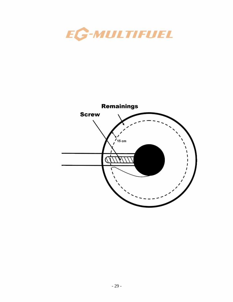
If this procedure is not fulfilled there might be perturbation in the feeder
system that might trigger the automatic shutdown. It is necessary to regularly
check the level of biomass in the silo. Filling of the silo must be done when the
screw is completely exposed (see diagram below). Never allow for situation that
the boiler is working when silo is empty, this might cause damage to the heat
exchanger.
- 29 -
- 30 -
6) EXHAUST OUTLET DUCT:
Once a year:
- take off the exhaust duct;
- unscrew the exhaust extractor screws and take it off, without disconnecting it;
- unscrew the bolt that holds the exhaust box and take it off;
- clean it using vacuum cleaner;
- do not touch the turbulator, they shouldn’t be under any circumstances
disassembled;
- take the cover of fire tube;
- check if the condition of combustion chamber and use a brush to clean the
burner and the chamber. The chamber can never be removed;
- put back on the cover of fire tube;
- mount the exhaust box again and extractor making sure that supports are clean
to prevent entering of unwanted air;
- place back the exhaust duct.
In this model the throat of the burner is not dismountable. It
is integrated with the burner.

- 31 -
VI) MAINTAINING THE BOILER
If the cause of the fault is not known, there should be no changes made to
any settings. Please contact:
- Boiler fitter
Company:.........................................................................................................................
Adress:..............................................................................................................................
Surname:............................................................................................................................
First name:...........................................................................................................................
Phone:.................................................................................................................................
- Zakład Ślusarski Greń Sp. J.
Tel.: +48 32 326 34 70, +18 32 210 16 26
Fax.: +48 32 326 34 72
Error messages:
Negative pressure gauge error:
Variable speed controller damaged. To make sure please check
information on the speed controller, and refer to it;
Exhaust extractor motor fault.
Lambda sensor error:
Check with the provided specification if the polarity is correct;
Check if sensor is heated with correct voltage: 12 Volt;
The sensor is damaged. To continue using the boiler please confirm
the option <<functioning without a sensor>>.
Exhaust error:
Check if sensor is not damage;
Excessive power given by the boiler.
Too high temperature error:
Wait until the temperature of the boiler is 60˚C, next arm the aquastat
by taking off the black cover and pressing the white button.
Silo extractor error:
- 32 -
Turn off and back on the left automatic switch. If the error is displayed
again check the silo, make sure that there’s no big piece of wood
jammed in the screw;
At the same time check if pieces of wood are not too big.
Too much of biomass error:
Stoppage of the boiler in spite of numerous tries to start. This
indicates that boiler is taking too much of biomass (check if the
program is adequate to the used biomass).
Boiler feeder screw error:
Turn on the middle automatic switch and once again start the boiler. If
the error is displayed again, it means that excessively big chunks of
wood are jammed in the feeder screw. Dismount the screw and bring
the boiler back to operation.
Ash removing screw error:
Turn on the right automatic switch and attempt to start the boiler one
more time. If the error is displayed again, it means that the screw must
have been jammed with a rock. Dismount the screw and bring the
boiler back to operation.
Ignition error:
Check if ignition is working properly;
Check if the silo is filled with biomass;
Check if the biomass is not too damp.
T water 250 error:
Sensor is damaged.

- 33 -
VIII) CONDITIONS OF SALES AND WARRANTY
EXTRACT FROM THE GENERAL CONDITIONS OF SALE AND WARRANTY
Warranty covers all the construction and material faults that the boiler is
made of for a period of:
- actual boiler made of steel 5 years
- fireproof concrete parts 3 years
- boiler feeder screw and silo extractor 2 years
- electrical components and controls of the boiler 1 year
Warranty covers only faults when the humidity of the biomass does not
exceed 25% and granulometry of 30 mm x 30 mm and 5 mm girth at most,
excluding all foreign objects, such as rocks, pebbles etc. Fitting of the boiler must
be performed by qualified specialist, in accordance with rules, regulation and
best practice, as well as with all the indications specified in this instruction
manual. Boilers that nominal power is lower than actual demand are not covered
by the warranty (nominal power must always exceed the power demand). Fitting
of the thermostatic valve that opens in 45˚C is mandatory to ensure proper
boiler safety. Electrical and electronic equipment is not covered by this warranty
if subjected to atmospheric discharge, moist, excessive voltage, fire etc.
Warranty covers repairs done on site, simple parts replacement that are
considered by manufacturer by damaged/faulty. The cost of delivery and
dismounting are covered by customer with no return considered. Repairs,
modification or replacement that occurs during the warranty period cannot be
done only to prolong the warranty period.
Warranty is not in effect if the efficiency of water has not been tested,
when analyzing the water indicated that it was necessary.
Warranty does not give right to claim any compensation. It is mandatory
to return the warranty card in 10 days from boiler delivery. Not returning the
warranty card will result in loss of warranty coverage. All customer orders,
distributor and sales representatives’ commitments are binding only after
written consent from Greń Company. Greń Company reserves the right to modify
the equipment if it finds it fit. Powers indicated in the price lists are maximal
powers. For more information please check the technical specification. Weights,
- 34 -
dimensions, efficiency etc. Included in catalog, newsletters and price lists are
only informational and should not be considered an offer.
Delivery dates are only informational and do not give right to claim any
compensation. The fact of ordering, is unequivocal with accepting these terms
and conditions. Any contradictory clauses are not in effect unless with written
confirmation from Greń Company.
All sold equipment remains full property of Greń Company until paid in
full.
Every risk and liability connected with storage of the merchandise by
Metal-worker Company Greń, which price and costs has not been covered falls on
the buyer.
To protect the interests of Greń Company, the buyer commits to purchase
insurance without any reimbursement or participation in costs, for merchandise
that has been purchased but not paid in full.

- 35 -
Zakład Ślusarski Greń Sp. J.
ul. Karola Miarki 1b
43-200 Pszczyna
Warranty card
Valid only if copy is returned to manufacturer (address specified below)
within 10 days from delivery. (See general terms)
MULTIFUEL Series
- actual boiler made of steel................................................5 years
- fireproof concrete parts....................................................3 years
- boiler feeder screw and silo extractor.............................2 years
- electrical components and controls of the boiler...........1 year
Surname: ............................................................
First name...........................................................
Address: ..................................................................
Phone: ..................................................................
Aware of the warranty terms, I commit to comply with manufacturers
recommendations.
Warranty reservations:
..................................................................................................................................
............................................................................................................................. .....
..................................................................................................................................
............................................................................................................................. .....
..................................................................................................................................
............................................................................................................................. .....
Greń company is not liable for the reservations above. Any irregularities in the
boiler functioning that are recorded by the company technician will result in
immediate cease of boiler operation. It is the customers responsibility to ensure
full boiler operation and maintenance. In case the technician will have to perform
additional starting of the boiler, there will be additional invoice issued to the
customer.
- 36 -
Boiler details:
Type: AUTO ............................................................................
Serial number: ..........................................................................
Delivery date: ............................................................................
Starting date: ....................................................................
Fitter’s signature: (familiarized)
Customer’s signature: (familiarized)
- 37 -
DLA KLIENTA DO ZWROTU Zakład Ślusarski Greń Sp. J.
ul. Karola Miarki 1b
43-200 Pszczyna
Warranty card
Valid only if copy is returned to manufacturer (address specified below)
within 10 days from delivery. (See general terms)
MULTIFUEL Series
- actual boiler made of steel................................................5 years
- fireproof concrete parts....................................................3 years
- boiler feeder screw and silo extractor.............................2 years
- electrical components and controls of the boiler...........1 year
Surname: ............................................................
First name...........................................................
Address: ..................................................................
Phone: ..................................................................
Aware of the warranty terms, I commit to comply with manufacturers
recommendations.
Warranty reservations:
............................................................................................................................. .....
..................................................................................................................................
............................................................................................................................. .....
..................................................................................................................................
............................................................................................................................. .....
..................................................................................................................................
Greń company is not liable for the reservations above. Any irregularities in the
boiler functioning that are recorded by the company technician will result in
immediate cease of boiler operation. It is the customer’s responsibility to ensure
- 38 -
full boiler operation and maintenance. In case the technician will have to perform
additional starting of the boiler, there will be additional invoice issued to the
customer.
Boiler details:
Type: AUTO............................................................................
Serial number: ..........................................................................
Delivery date: ............................................................................
Starting date: ....................................................................
Fitter’s signature: (familiarized)
Customer’s signature: (familiarized)
- 39 -

- 40 -