kobold model kdm variable area flowmeter user instructions · kobold model kdm variable area...
TRANSCRIPT
Kobold Model KDM Variable Area Flowmeter
User Instructions
KOBOLD Instruments Inc. 1801 Parkway View Drive Pittsburgh PA 15205
Phone (412) 788-2830 • Fax (412)-788-4890 • www.koboldusa.com
Manual-KDM_08-10-06

KDM
FM Rev. 8/10/06
Contents
1.0 General 12.0 Specifications 13.0 Installation Instructions 6
3.1 Flowmeter Installation 63.2 Electrical Connections 8
4.0 Operation 124.1 Prevention of Mechanical Damage Due to Water Hammer 124.2 Flow Switch Adjustment 124.3 Correction Factors for Compressed Gas Service 13
5.0 Maintenance 145.1 Metering Tube Cleaning 14
6.0 Arrival of Damaged Goods 147.0 Need Help With Your Flowmeter? 14
List of TablesTable 2.1 Dimensions 3Table 2.2 Available Flow Ranges 4Table 2.3 Model Number Information 5Table 2.4 Temperature Limits With Options 6Table 3.1 Flange Installation Data 7
List of DiagramsDiagram 1.1 Principle of Operation 1Diagram 2.1 Dimensions 3Diagram 3.1 Limit Switch Connections 8Diagram 3.2 Analog Transmitter Electrical Connections 10Diagram 3.3 Totalizer Module 11Diagram 3.4 Wiring for 4-20 mA Transmitter and Totalizer 11Diagram 4.1 Switch Adjustment 12Diagram 4.2 Gas Correction Factor Equation 13

KDM
FM Rev. 8/10/06
CAUTION: For safety reasons, please read the cautionary information located at the end of the manual, before attempting installation.
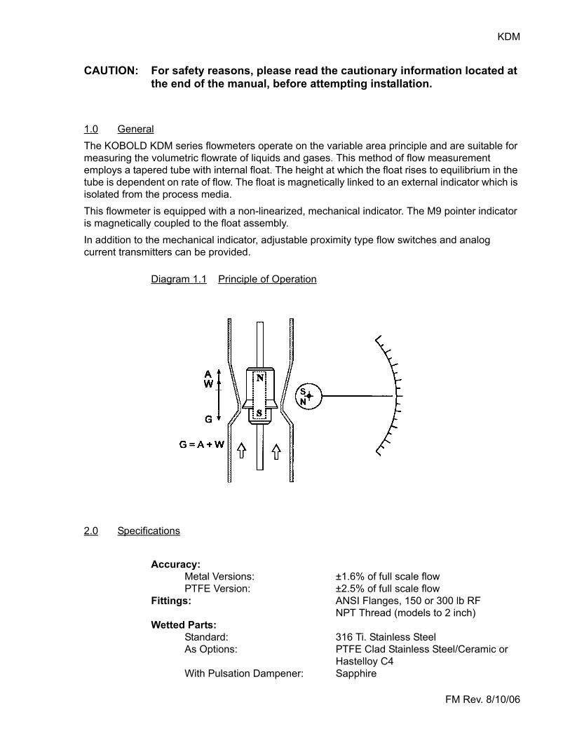
1.0 GeneralThe KOBOLD KDM series flowmeters operate on the variable area principle and are suitable for measuring the volumetric flowrate of liquids and gases. This method of flow measurement employs a tapered tube with internal float. The height at which the float rises to equilibrium in the tube is dependent on rate of flow. The float is magnetically linked to an external indicator which is isolated from the process media. This flowmeter is equipped with a non-linearized, mechanical indicator. The M9 pointer indicator is magnetically coupled to the float assembly. In addition to the mechanical indicator, adjustable proximity type flow switches and analog current transmitters can be provided.
Diagram 1.1 Principle of Operation
2.0 Specifications
Accuracy:Metal Versions: ±1.6% of full scale flowPTFE Version: ±2.5% of full scale flow
Fittings: ANSI Flanges, 150 or 300 lb RFNPT Thread (models to 2 inch)
Wetted Parts:Standard: 316 Ti. Stainless SteelAs Options: PTFE Clad Stainless Steel/Ceramic or
Hastelloy C4With Pulsation Dampener: Sapphire
KDM 2
FM Rev. 8/10/06
2.0 Specifications (Cont.)Operating Temperature:
Ambient: -10 to 140°FMedium:With no Options: -110 to 390°FWith Options: See Table 2.4PTFE Clad: -110 to 160°F
Maximum PressureFlanged: Per ANSI flange class ratingThreaded: 580 PSIG
Electrical Characteristics:SwitchesStandard Switch
Type: ProximityPower Requirement: 10-30 VDCOutput Characteristic: PNP, output voltage = Vsupply-3V,
100 mA MaxQuantity: 2 maximum
Intrinsically Safe SwitchType: ProximityOutput Characteristic: NAMUR per DIN 19234Quantity: 2 maximumRatings for Intrinsic Safety: See Section 3.2.3
Analog Output:Standard Output:
Type: 2-wire 4-20 mASupply Voltage Range: 12.7 to 30 VDCMax Loop Resistance: 35 to 900 Ohms (supply voltage
dependent. See Diagram 3.3)Intrinsically Safe Analog Output
Type: 2-wire 4-20 mASupply Voltage Range: 12.7 to 30 VDCMax Loop Resistance: 35 to 900 Ohms (supply voltage
dependent. See Diagram 3.3)Ratings for Intrinsic Safety: See Section 3.2.5
Electrical Protection: NEMA 4
Totalizing DisplayType: 6 Digit LED, resettablePower Requirement: Loop powered by analog output loop(Not available with intrinsically safe analog output)
3 KDM
FM Rev. 8/10/06
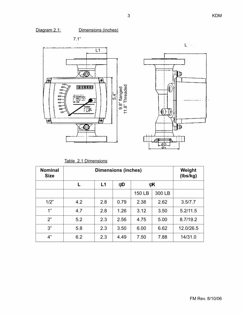
Diagram 2.1: Dimensions (inches)
Table 2.1 Dimensions
Nominal Size
Dimensions (inches) Weight (lbs/kg)
L L1 φD φK
150 LB 300 LB
1/2” 4.2 2.8 0.79 2.38 2.62 3.5/7.7
1” 4.7 2.8 1.26 3.12 3.50 5.2/11.5
2” 5.2 2.3 2.56 4.75 5.00 8.7/19.2
3” 5.8 2.3 3.50 6.00 6.62 12.0/26.5
4” 6.2 2.3 4.49 7.50 7.88 14/31.0
7.1”
5.4”
9.8”
flan
ged
11.8
” Thr
eade
d
LL1
KDM 4
FM Rev. 8/10/06
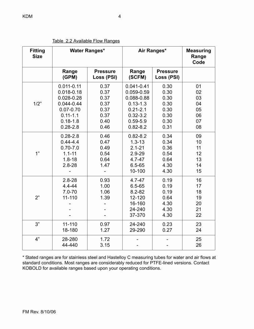
* Stated ranges are for stainless steel and Hastelloy C measuring tubes for water and air flows at standard conditions. Most ranges are considerably reduced for PTFE-lined versions. Contact KOBOLD for available ranges based upon your operating conditions.
Table 2.2 Available Flow Ranges
Fitting Size
Water Ranges* Air Ranges* Measuring Range Code
Range (GPM)
Pressure Loss (PSI)
Range(SCFM)
Pressure Loss (PSI)
1/2”
0.011-0.110.018-0.180.028-0.280.044-0.440.07-0.700.11-1.10.18-1.80.28-2.8
0.370.370.370.370.370.370.400.46
0.041-0.410.059-0.590.088-0.880.13-1.30.21-2.10.32-3.20.59-5.90.82-8.2
0.300.300.300.300.300.300.300.31
0102030405060708
1”
0.28-2.80.44-4.40.70-7.01.1-111.8-182.8-28
-
0.460.470.490.540.641.47
-
0.82-8.21.3-132.1-212.9-294.7-476.5-6510-100
0.340.340.360.540.644.304.30
09101112131415
2”
2.8-284.4-447.0-7011-110
---
0.931.001.061.39
---
4.7-476.5-658.2-8212-12016-16024-24037-370
0.190.190.190.644.304.304.30
16171819202122
3” 11-11018-180
0.971.27
24-24029-290
0.230.27
2324
4” 28-28044-440
1.723.15
--
--
2526
5 KDM
FM Rev. 8/10/06
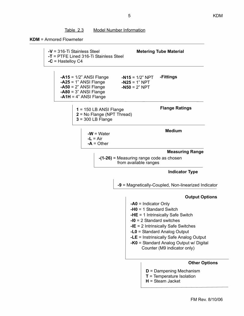
Table 2.3 Model Number Information
KDM = Armored Flowmeter
Metering Tube Material-V = 316-Ti Stainless Steel-T = PTFE Lined 316-Ti Stainless Steel-C = Hastelloy C4
-Fittings-A15 = 1/2” ANSI Flange-A25 = 1” ANSI Flange-A50 = 2” ANSI Flange-A80 = 3” ANSI Flange-A1H = 4” ANSI Flange
-N15 = 1/2” NPT-N25 = 1” NPT-N50 = 2” NPT
Flange Ratings1 = 150 LB ANSI Flange2 = No Flange (NPT Thread)3 = 300 LB Flange
Medium-W = Water-L = Air-A = Other
Measuring Range-(1-26) = Measuring range code as chosen
from available ranges
Indicator Type
-9 = Magnetically-Coupled, Non-linearized Indicator
-A0 = Indicator Only-H0 = 1 Standard Switch-HE = 1 Intrinsically Safe Switch-I0 = 2 Standard switches-IE = 2 Intrinsically Safe Switches-L0 = Standard Analog Output-LE = Instrinsically Safe Analog Output-K0 = Standard Analog Output w/ Digital
Counter (M9 indicator only)
Output Options
Other Options
D = Dampening Mechanism
H = Steam JacketT = Temperature Isolation
KDM 6
FM Rev. 8/10/06
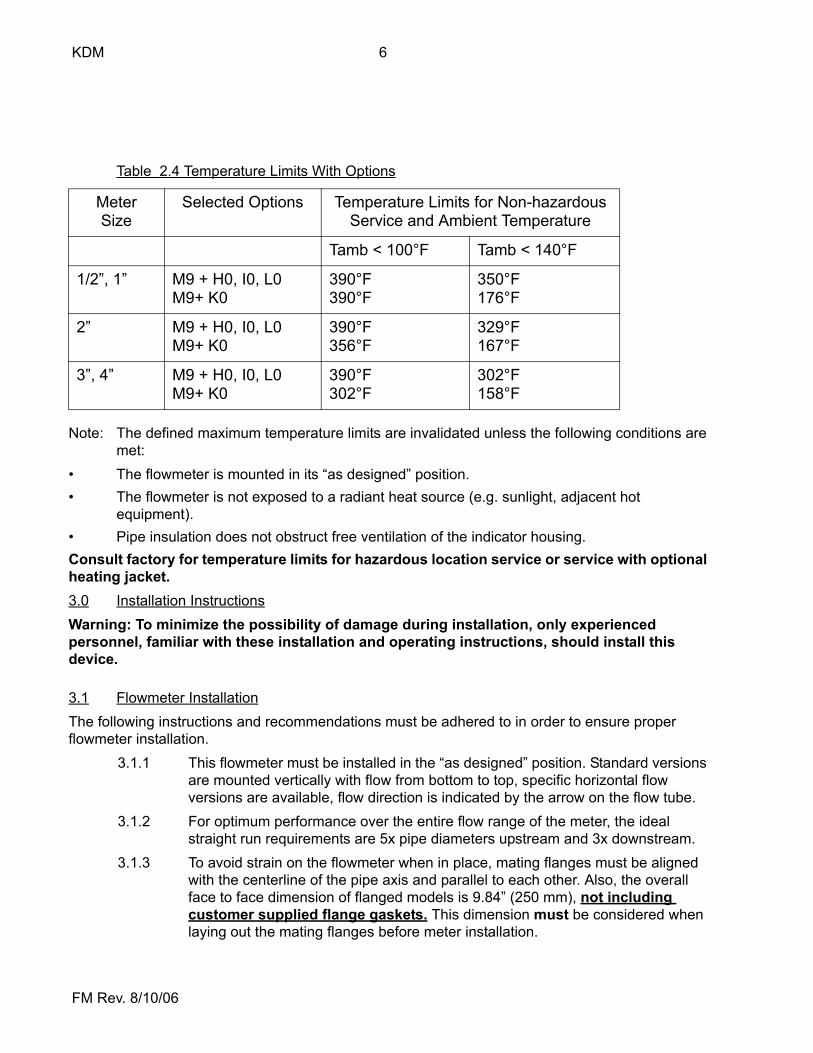
Note: The defined maximum temperature limits are invalidated unless the following conditions are met:
• The flowmeter is mounted in its “as designed” position.• The flowmeter is not exposed to a radiant heat source (e.g. sunlight, adjacent hot
equipment).• Pipe insulation does not obstruct free ventilation of the indicator housing.Consult factory for temperature limits for hazardous location service or service with optional heating jacket.3.0 Installation InstructionsWarning: To minimize the possibility of damage during installation, only experienced personnel, familiar with these installation and operating instructions, should install this device.
3.1 Flowmeter InstallationThe following instructions and recommendations must be adhered to in order to ensure proper flowmeter installation.
3.1.1 This flowmeter must be installed in the “as designed” position. Standard versions are mounted vertically with flow from bottom to top, specific horizontal flow versions are available, flow direction is indicated by the arrow on the flow tube.
3.1.2 For optimum performance over the entire flow range of the meter, the ideal straight run requirements are 5x pipe diameters upstream and 3x downstream.
3.1.3 To avoid strain on the flowmeter when in place, mating flanges must be aligned with the centerline of the pipe axis and parallel to each other. Also, the overall face to face dimension of flanged models is 9.84” (250 mm), not including customer supplied flange gaskets. This dimension must be considered when laying out the mating flanges before meter installation.
Table 2.4 Temperature Limits With Options
MeterSize
Selected Options Temperature Limits for Non-hazardousService and Ambient Temperature
Tamb < 100°F Tamb < 140°F
1/2”, 1” M9 + H0, I0, L0M9+ K0
390°F390°F
350°F176°F
2” M9 + H0, I0, L0M9+ K0
390°F356°F
329°F167°F
3”, 4” M9 + H0, I0, L0M9+ K0
390°F302°F
302°F158°F
7 KDM
FM Rev. 8/10/06
3.1.4 In order to prevent damage to the flowmeter caused by water hammer, the flowmeter should be kept filled with fluid at all times. To achieve this, locate shut off and control valves down stream of the flowmeter. If fluid can back flow out of the meter when the system is shut down, a check valve should be installed upstream of the flowmeter.
3.1.5 The pipeline must be rigidly supported at the inlet and outlet of the flowmeter. This will prevent axial stresses which can be exerted on the flowmeter by the weight of the fluid-filled pipe. It will also prevent cyclic stresses caused by pipe vibration.
3.1.6 Flowmeters for compressed gas service are calibrated for a specific operating pressure at the outlet of the flowmeter. This pressure is stamped on the indicator. In order to ensure an accurate reading, this pressure must be maintained at the flowmeter outlet at all times. If pressure fluctuations are likely, a pressure regulating valve should be installed.
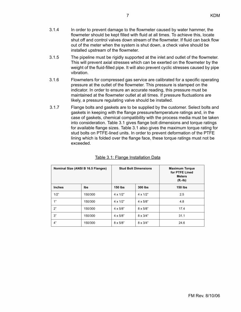
3.1.7 Flange bolts and gaskets are to be supplied by the customer. Select bolts and gaskets in keeping with the flange pressure/temperature ratings and, in the case of gaskets, chemical compatibility with the process media must be taken into consideration. Table 3.1 gives flange bolt dimensions and torque ratings for available flange sizes. Table 3.1 also gives the maximum torque rating for stud bolts on PTFE-lined units. In order to prevent deformation of the PTFE lining which is folded over the flange face, these torque ratings must not be exceeded.
Table 3.1: Flange Installation Data
Nominal Size (ANSI B 16.5 Flanges) Stud Bolt Dimensions Maximum Torque for PTFE Lined
Meters(ft.-lb)
Inches Ibs 150 lbs 300 lbs 150 lbs
1/2” 150/300 4 x 1/2” 4 x 1/2” 2.5
1” 150/300 4 x 1/2” 4 x 5/8” 4.8
2” 150/300 4 x 5/8” 8 x 5/8” 17.4
3” 150/300 4 x 5/8” 8 x 3/4” 31.1
4” 150/300 8 x 5/8” 8 x 3/4” 24.6
KDM 8
FM Rev. 8/10/06
3.2 Electrical Connections
3.2.1 General Wiring RequirementsIn order to conform with the electrical protection category of the flowmeters, adhere to the following general wiring instructions and precautions:
• Use jacketed, multi-conductor cable with an outside jacket diameter of 0.20” to 0.39”. After passing the cable through the cable entry, make sure to tighten the cable gland nut.
• Do not remove the blanking plugs on unused cable entries or water entry into the housing may result.
• Provide enough slack in the cable to provide a water drip point (U-bend) in the cable prior to its entry into the flowmeter
3.2.2 Limit SwitchesThe optional limit switches which can be provided with this flowmeter are inductive type proximity switches. They are available in an intrinsically safe or non-intrinsically safe version. The intrinsically safe switches have a NAMUR output per DIN 19234. These intrinsically safe switches require an intrinsically safe relay in order to sense limit switch activation and provide a dry contact for control circuits. The KOBOLD series REL- intrinsically safe relays are recommended for this application.The standard, non-intrinsically safe switch, has a PNP, open-collector transistor output. The switch operates on a supply voltage of 10-30 VDC. See section 2.0 Specifications, for additional informationElectrical connections for the limit switches are made at terminals inside the meter housing as follows:
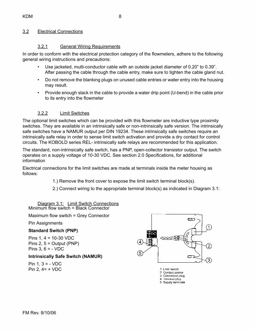
1.) Remove the front cover to expose the limit switch terminal block(s).2.) Connect wiring to the appropriate terminal block(s) as indicated in Diagram 3.1:
Diagram 3.1: Limit Switch ConnectionsMinimum flow switch = Black ConnectorMaximum flow switch = Grey ConnectorPin AssignmentsStandard Switch (PNP)Pins 1, 4 = 10-30 VDCPins 2, 5 = Output (PNP)Pins 3, 6 = - VDCIntrinsically Safe Switch (NAMUR)Pin 1, 3 = - VDCPin 2, 4= + VDC
9 KDM
FM Rev. 8/10/06
3.2.3 Limit Switch Installation In Hazardous LocationsThe intrinsically safe version of the limit switches (Suffix: -HE or IE) provided with this flowmeter are manufactured by Pepperl & Fuchs and have Factory Mutual (FM) system approval for use in hazardous locations. For this approval to be valid, an approved intrinsically safe barrier must be used and installation must be in accordance with the National Electric Code, ANSI/NFPA 70, Article 504, and ANSI/ISA RP12.6. Additionally, there are ambient and process temperature limits which must be adhered to.IMPORTANT: Flowmeter installation in hazardous locations limits the allowable ambient and process temperatures. If the process temperature is expected to be > 185°F or if the ambient temperature is expected to be > 100°F, consult KOBOLD Instruments for the maximum temperature limits prior to ordering and installation.The KOBOLD REL- series of intrinsically safe isolators/relays are approved for use with these limit switches. The REL- series provides an intrinsically safe sensing circuit to which the limit switch is connected and provides a SPDT output relay for control circuits.The entity parameters of the intrinsically-safe switches are as follows:
Maximum No-load Voltage(Vi): 16 VDCMaximum Short Circuit Current(Ii): 25 mA DCMaximum Output Power Capability(Pi): 34 mWMaximum Internal Self Capacitance(Ci): 150 nFMaximum Internal Self Inductance(Li): 0.15 mHHazardous Area Classification: Cert. # 3024297Hazardous Area Approvals: CL 1, Div 2, Groups A,B,C,D
CL 1, Zone 2, Group IIC T6 @ 60°C
IMPORTANT: Refer to KOBOLD control drawings: KDM-IS100 and KDM-NI200 for additional information.The following electrical characteristics are relevant for the limit switches when installed in hazardous locations:Output Type: NAMUR per DIN 19234Current Consumption:
Activated: > 3 mANot Activated: < 1 mA

KDM 10
FM Rev. 8/10/06
3.2.5 Analog Transmitter Installation in Hazardous LocationsIf the intrinsically safe version of the analog transmitter (Suffix: -LE) is purchased, it carries the Factory Mutual (FM) certification for installation in hazardous locations. In order to function as an intrinsically-safe device, the analog transmitter must be connected to an approved intrinsically safe power supply/isolator. The entity parameters of the intrinsically-safe transmitter are as follows:
Maximum No-load Voltage(Vi): 30 VDCMaximum Short Circuit Current(Ii): 100 mA DCMaximum Output Power Capability(Pi): 1 WattMaximum Internal Self Capacitance(Ci): 20 nFMaximum Internal Self Inductance(Li): 0 mHHazardous Area Classification: Cert # 3024297Hazardous Area Approvals: CL 1, Div 1, Groups A,B,C,D T6 @ 60°C
CL 1, Div 2, Groups A,B,C,DCL 1, Zone 2, Group IIC T6 @ 60°C
IMPORTANT: Refer to KOBOLD control drawings KDM-IS100 and KDM-NI200 for additional information.
IMPORTANT: Flowmeter installation in hazardous locations limits the allowable ambient and process temperatures. If the process temperature is expected to be > 185°F or if the ambient temperature is expected to be > 100°F, consult KOBOLD Instruments for the maximum temperature limits prior to ordering and installation.The PTB certification is valid for compressed gases only if the gas is non-explosive and the flowmeter is included in periodic piping pressure tests.
KDM
11
12
+
-
+-
12.7 to 30 VDC
4-20 mA DCDisplay/Peripheral
4-20 mA Loop Resistance Limits
12.735
Supply Voltage (VDC)
Max. Loop Resistance (Ohms)
30
25
20
15
100 300 500 700 900
R loop Max. = V supply - 12.70.02
3.2.4 Analog TransmitterAn optional 4-20 mA analog transmitter can be provided with this flowmeter. Electrical connections for the analog transmitter are made at terminals inside the flowmeter housing as follows:
To expose the analog transmitter terminal strip, remove the front cover.
Diagram 3.2: Analog Transmitter Electrical Connections
11 KDM
FM Rev. 8/10/06
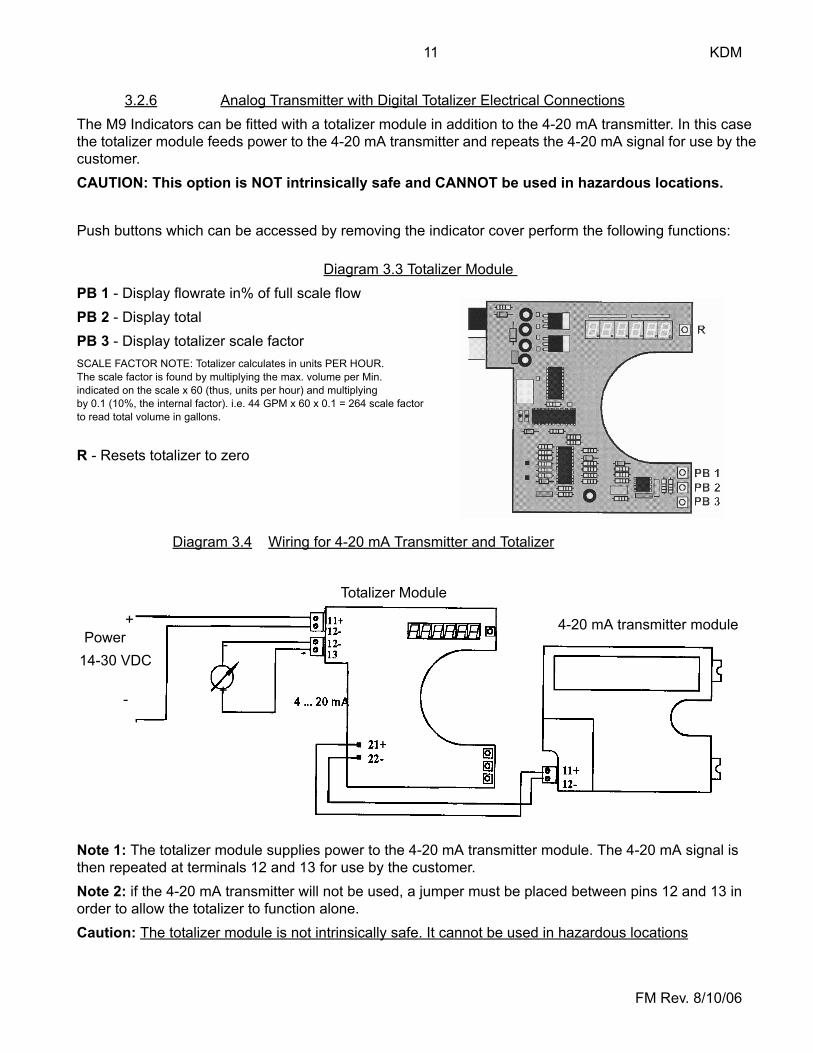
3.2.6 Analog Transmitter with Digital Totalizer Electrical ConnectionsThe M9 Indicators can be fitted with a totalizer module in addition to the 4-20 mA transmitter. In this case the totalizer module feeds power to the 4-20 mA transmitter and repeats the 4-20 mA signal for use by the customer.CAUTION: This option is NOT intrinsically safe and CANNOT be used in hazardous locations.
Push buttons which can be accessed by removing the indicator cover perform the following functions:
Diagram 3.3 Totalizer Module PB 1 - Display flowrate in% of full scale flowPB 2 - Display totalPB 3 - Display totalizer scale factorSCALE FACTOR NOTE: Totalizer calculates in units PER HOUR. The scale factor is found by multiplying the max. volume per Min. indicated on the scale x 60 (thus, units per hour) and multiplying by 0.1 (10%, the internal factor). i.e. 44 GPM x 60 x 0.1 = 264 scale factor to read total volume in gallons.
R - Resets totalizer to zero
Diagram 3.4 Wiring for 4-20 mA Transmitter and Totalizer
Note 1: The totalizer module supplies power to the 4-20 mA transmitter module. The 4-20 mA signal is then repeated at terminals 12 and 13 for use by the customer.Note 2: if the 4-20 mA transmitter will not be used, a jumper must be placed between pins 12 and 13 in order to allow the totalizer to function alone.Caution: The totalizer module is not intrinsically safe. It cannot be used in hazardous locations
+
-
14-30 VDCPower
+
-
Totalizer Module
4-20 mA transmitter module
KDM 12
FM Rev. 8/10/06
4.0 Operation
4.1 Prevention of Mechanical Damage Due to Water HammerUndoubtedly, the majority of failures which occur in mechanical flowmeters is caused by water hammer. Water hammer occurs when flow is quickly started or stopped in a fluid system. When flow is quickly initiated, the lack of back pressure in the system which was originally at rest results in a brief flow transient which may exceed the measuring device’s range by several times. When flow is quickly secured, stored momentum in the fluid which was originally moving and is suddenly brought to a halt causes a pressure surge which can exceed the normal operating pressure by several times. These flow and pressure transients can result in personal injury, permanent damage to a flowmeter’s components, i.e. float, bellows etc., or at a minimum can throw the meter out of calibration. During operation there are a number of situations to avoid which will minimize flowmeter damage due to water hammer:
• Follow the installation recommendations given in Section 3.1, Flowmeter Installation, to ensure that the piping remains full of fluid.
• Flow should be introduced slowly into the system. This will allow back pressure to develop in the system, thereby minimizing the initial flow transient which causes water hammer.
• System flow should also be secured slowly to minimize pressure surges which are caused my a sharp reduction in fluid velocity.
• If the flowmeter is being used in a compressed gas system, pressure should be slowly increased to normal operating pressure.
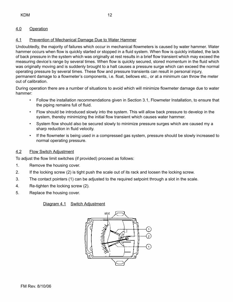
4.2 Flow Switch AdjustmentTo adjust the flow limit switches (if provided) proceed as follows:1. Remove the housing cover.2. If the locking screw (2) is tight push the scale out of its rack and loosen the locking screw.3. The contact pointers (1) can be adjusted to the required setpoint through a slot in the scale.4. Re-tighten the locking screw (2).5. Replace the housing cover.
Diagram 4.1 Switch Adjustment
13 KDM
FM Rev. 8/10/06
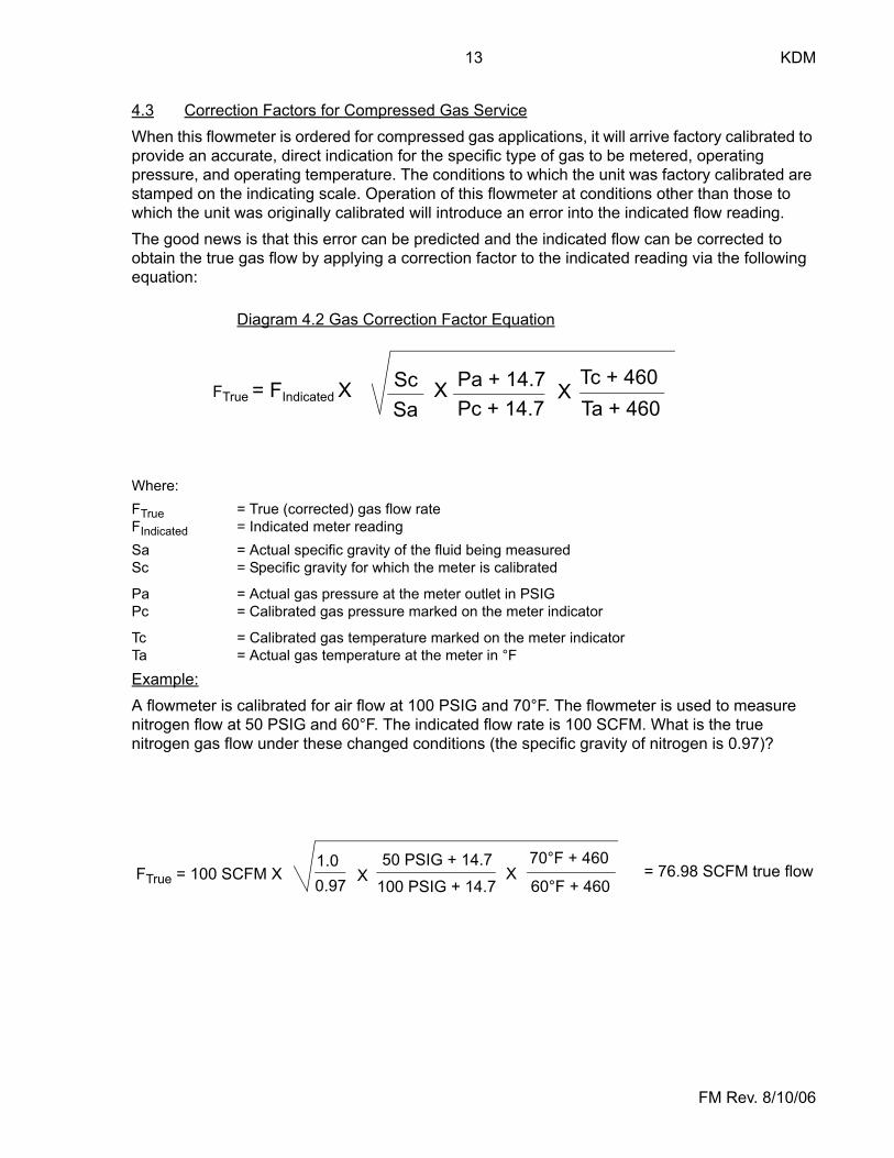
4.3 Correction Factors for Compressed Gas ServiceWhen this flowmeter is ordered for compressed gas applications, it will arrive factory calibrated to provide an accurate, direct indication for the specific type of gas to be metered, operating pressure, and operating temperature. The conditions to which the unit was factory calibrated are stamped on the indicating scale. Operation of this flowmeter at conditions other than those to which the unit was originally calibrated will introduce an error into the indicated flow reading. The good news is that this error can be predicted and the indicated flow can be corrected to obtain the true gas flow by applying a correction factor to the indicated reading via the following equation:
Diagram 4.2 Gas Correction Factor Equation
Where:FTrue = True (corrected) gas flow rateFIndicated = Indicated meter readingSa = Actual specific gravity of the fluid being measuredSc = Specific gravity for which the meter is calibrated
Pa = Actual gas pressure at the meter outlet in PSIGPc = Calibrated gas pressure marked on the meter indicator
Tc = Calibrated gas temperature marked on the meter indicatorTa = Actual gas temperature at the meter in °F
Example:A flowmeter is calibrated for air flow at 100 PSIG and 70°F. The flowmeter is used to measure nitrogen flow at 50 PSIG and 60°F. The indicated flow rate is 100 SCFM. What is the true nitrogen gas flow under these changed conditions (the specific gravity of nitrogen is 0.97)?
FTrue = FIndicated XSc Pa + 14.7 Tc + 460X XSa Pc + 14.7 Ta + 460
FTrue = 100 SCFM X1.00.97 100 PSIG + 14.7
50 PSIG + 14.7 70°F + 460
60°F + 460X X = 76.98 SCFM true flow
KDM 14
FM Rev. 8/10/06
5.0 \MaintenanceThis flowmeter normally requires no maintenance. Periodic cleaning of the metering tube inter-nals may be required if a buildup of dirt or other deposits occurs over time. Adding a filter upstream of the meter will minimize this problem.
5.1 Metering Tube CleaningTo clean the metering tube internals proceed as follows:
5.1.1 Remove the flowmeter from the piping system.5.1.2 Remove the snap ring at the flowmeter outlet connection. This snap ring locks
the float and guide rod into place.5.1.3 Remove the float and guide rod assembly from the metering tube.5.1.4 Clean the float, guide rod and metering tube internals with a solvent or clean-
ing fluid which is chemically compatible with all wetted parts.5.1.5 Reassemble the flowmeter in the manner in which it was disassembled.
6.0 Arrival of Damaged GoodsYour instrument was inspected prior to shipment and found to be defect-free. If damage is visible on the unit, we advise that you carefully inspect the packing in which it was delivered. If damage is visible, notify your local carrier at once. The carrier is liable for a replacement under these cir-cumstances. If your claim is refused, please contact KOBOLD Instruments.
7.0 Need Help With Your Flowmeter?Call one of our friendly engineers at (412)-788-2830
15 KDM
FM Rev. 8/10/06
CAUTION
PLEASE READ THE FOLLOWING GENERAL SAFE OPERATIONGUIDELINES BEFORE ATTEMPTING INSTALLATION OF YOUR NEW
DEVICE. FAILURE TO HEED THE INFORMATION HEREIN MAYRESULT IN EQUIPMENT FAILURE AND POSSIBLE SUBSEQUENT
PERSONAL INJURY

KDM 16
FM Rev. 8/10/06

17 KDM
FM Rev. 8/10/06
• User's Responsibility for Safety: KOBOLD manufactures a wide range of process sensors and technologies. While each of these technologies are designed to operate in a wide variety of applications, it is the user's responsibility to select a technology that is appropriate for the application, to install it properly, to perform tests of the installed system, and to maintain all components. The failure to do so could result in property damage or serious injury.
• Inspect instrument for damage upon arrival: Cracked, fractured, bent or otherwise damaged instruments must not be put into use, since the device is weakened to an unknown extent. Refer to Section 6.0, Arrival of Damaged Equipment, for additional information.
• Media and Chemical Compatibility: The maximum tolerances of the device have been determined using water and air. If using other media, especially corrosive media, it is critically important that the user determine chemical compatibility with our instruments. KOBOLD Instruments Inc. cannot accept responsibility for failure and consequences resulting from use of media other than water, air, and nitrogen.
• Material Compatibility: Make sure that the model which you have selected is chemically compatible with the application liquids. While the meter is liquid and spray resistant when installed properly, it is not designed to be immersed.
• Proper Installation in Flow System: Install the device in a fully supported position within your flow system. This avoids excessive stresses which may damage the instrument. In particular: a.) Ensure that the plumbing leading to and from the instrument is fully supported and that the instrument does not perform the physical function of a joint.b.) When calculating stress on the device caused by plumbing, the weight of the medium in the pipes must be considered as well.c.) Misaligned runs of rigid piping can cause large stresses when connected to the instrument. Do not connect in such a fashion.d.) Do NOT install by holding the device housing to provide counter-torque to the pipe fitting.e.) For threaded fittings, use an appropriate amount of TEFLON tape on male threads of fitting. This reduces the twisting stresses produced by tightening the fittings into each other.f.) Do not use pliers or wrenches on the housing, as this may damage it.g.) Do not overtighten, as this may fracture the fittings.
KDM 18
FM Rev. 8/10/06
• While Operating the Flow System: During operation, there are a number of situations to avoid:a.) The sudden cessation of fluid flow causes what is typically referred to as "water hammer". Most people are familiar with this phenomenon from their home experience - it is the cause behind the loud clank of water pipes which occurs when faucets are turned off too suddenly. The cause behind this "water hammer" is quite easy to visualize. Water is fairly massive. The amount of water in long runs of pipe is quite substantial. When the faucets are turned off suddenly, especially from a full on condition, the water has considerable momentum and does not want to stop flowing. The situation is similar to stopping a car by running into a wall, rather than by applying brakes. Both are sudden rather than gradual. The damage to the wall can be substantial (not to mention the car).b.) The "water hammer" causes surges in fluid pressure which could cause the measurement instrument's pressure limit to be exceeded, resulting in failure and possible personal injury.c.) Fluid surges, as well as the water hammer, can be particularly damaging to empty flowmeters since there is no back pressure in the device. The damage is caused, once again, by momentary excess pressure. To avoid these surges, fluid lines should remain full (if possible) and water flow should be introduced to the device slowly.d.) If the instrument is isolated with inlet and outlet valves, the flowmeter must be completely drained when said valves are both closed. Failure to do so could result in damage to the device caused by thermal expansion of fluid.e.) Freezing of water in the instrument must be avoided since the resultant expansion will damage the flowmeter and make it unsafe for use.
• Wiring and Electrical: Section 2.0, Specifications and Section 3.0, Electrical Connections, provide the voltage and current limitations and the wiring for the various sensor types. The sensor electrical ratings should never be exceeded. Electrical wiring of the sensor should be performed in accordance with all applicable national, state and local codes.
• Temperature and Pressure: Section 2.0, Specifications, provides the temperature and pressure limits for each model. Operation outside these limitations will cause damage to the unit and can potentially cause personal injury. Fluid should never be allowed to freeze inside the sensor.
• Make a Fail-safe System: Design a fail-safe system that accommodates the possibility of switch or power failure. In critical applications, KOBOLD recommends the use of redundant backup systems and alarms in addition to the primary system.